1
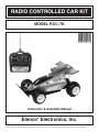
RADIO CONTROLLED CAR KIT
MODEL RCC-7K
Instruction & Assembly Manual
Elenco Electronics, Inc.
®
Copyright © 2005, 2001 by Elenco® Electronics, Inc. All rights reserved.
Revised 2005
REV-I
753288-I
No part of this book shall be reproduced by any means; electronic, photocopying, or otherwise without written permission from the publisher.
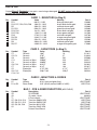
PARTS LIST
Contact Elenco® Electronics if any parts are missing or damaged. DO NOT contact your place of purchase
as they will not be able to help you.
CARD 1 - RESISTORS (in Bag 2)
Qty.
1
5
1
2
2
2
1
2
2
1
2
Symbol
R11
R12, R17, R18, R19, R20
R5
R1, R21
R13, R14
R15, R16
R10
R4, R8
R2, R3
R9
R6, R7
Value
68Ω 5% 1/4W
100Ω 5% 1/4W
200Ω 5% 1/4W
560Ω 5% 1/4W
1kΩ 5% 1/4W
1.5kΩ 5% 1/4W
2.7kΩ 5% 1/4W
3.3kΩ 5% 1/4W
22kΩ 5% 1/4W
200kΩ 5% 1/4W
3.9MΩ 5% 1/4W
Marking
blue-gray-black-gold
brown-black-brown-gold
red-black-brown-gold
green-blue-brown-gold
brown-black-red-gold
brown-green-red-gold
red-violet-red-gold
orange-orange-red-gold
red-red-orange-gold
red-black-yellow-gold
orange-white-green-gold
Part #
126800
131000
132000
135600
141000
141500
142700
143300
152200
162000
173900
CARD 2 - CAPACITORS (in Bag 2)
Qty.
1
2
1
1
1
2
1
1
4
Symbol
C1
C2, C3
C8
C11
C4
C9, C10
C7
C5
C6, C12,
C13, C14
Type
Ceramic
Ceramic
Ceramic
Ceramic or
Ceramic or
Ceramic or
Ceramic or
Electrolytic
Electrolytic
Mylar
Mylar
Mylar
Mylar
Value
10pF
27pF
500pF
2200pF
3300pF
0.01µF
0.1µF
4.7µF 50V
220µF 10V
Marking
10
27
501
222
332
103
104
4.7µF
220µF
Part #
211011
213010
225080
232217
233310
241031
251017
264747
282244
CARD 2 - INDUCTORS & DIODES
Qty.
1
1
Symbol
L2
D1 or D2
Type
Inductor
Zener Diode
Qty.
1
1
1
4
4
4
1
1
Symbol
IC1
IC1
T1
Q7, Q8, Q13, Q14
Q5, Q6, Q11, Q12
Q2, Q3, Q9, Q10
Q1
-
Value
8.2µH (gray-red-gold-silver)
3.0V (usually marked 3.0B2 or 3.6B1)
BAG 1 - PCB & SEMICONDUCTORS
Description
IC SCRX2BC
IC socket, 16-pin
9 Turn inductor
Transistor S8050, NPN
Transistor S8550, PNP
Transistor 9014, NPN
Transistor C945, NPN
Printed Circuit Board
Part #
6RCC7K02E
6RCC7K41
(6RCC7KB1E)
Part #
6RCC7K01E
664016
6RCC7K03E
6RCC7K04
6RCC7K05
6RCC7K06E
6RCC7K07E
6RCC7K10E
-1-
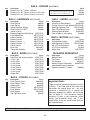
BAG 3 - SCREWS
Qty.
5
4
3
Description
Part #
Screws 0.4” x 0.1” (10mm x 2.6mm)
Screws 0.3” x 0.1” (8mm x 2.6mm), 0.15” head
Screws 0.3” x 0.1” (8mm x 2.6mm), 0.2” head
BAG 4 - HARDWARE
Qty.
2
1
2
1
1
2
1
1
2
1
1
1
1
1
1
1
1
1
1
1
1
1
Rear Springs
Front Spring
Shock Absorber Springs
Rear Rod 0.8” x 0.075”
(20mm x 2mm)
Steering Alignment Wire/Spring
Front Wheel Bars
Battery Contact, +
Battery Contact, –
Battery Contact, + –
Battery Contact, – +
Switch, on/off
Rear Axle
Transmitter Antenna
1
1
1
1
2
2
1
Qty.
680023
680024
680025
610808
2
2
1
1
1
1
6RCC7K11
6RCC7K12E
6RCC7K13E
6RCC7K14E
6RCC7K15E
6RCC7K16E
6RCC7K18E
662019E1
484010E
Description
Light Bulb, with wires attached
4” wire, red
4” wire, blue
4” wire, black
4” wire, green
4” wire, yellow
4” wire, orange
4” wire, white
Solder Roll
Description
Front Section Cover
Rear Section Cover
Steering Bar
Battery Cover
Front Wheels
Rear Wheels
Top Light Bulb Cover
BAG 7 - GEARS
Part #
1
1
1
1
2
640101
640102
640102E
(6RCC7KB7E)
Description
Part #
Locators for Rear Wheels
626019E3
Turning Posts for Front Wheels 6RCC7K34E
Steering Alignment Post
6RCC7K36E
Gear, Rear Wheels Axle
626019E4
Steering Motor Bracket
626018E2
Gear, middle of rear section
610809
BAG 8 - MOTORS
Qty.
(6RCC7KB5E)
BAG 6 - COVERS
Qty.
You may have been given different screws from
those specified here (and usually some spares).
Contact Elenco® if it is not clear which to use.
(6RCC7KB4E)
Description
BAG 5 - WIRES
Qty.
(6AK870B1E)
(6RCC7KB8E)
Description
Driving Motor (larger)
Steering Motor (smaller)
0.01µF Disc Capacitors
0.1µF Disc Capacitors
Motor Gear
Part #
6RCC7K39
6RCC7K40E
241031
251010
6RCC7K37
PACKAGED SEPARATELY
Part #
Qty.
6RCC7K21
6RCC7K22
6RCC7K23
6RCC7K24
6RCC7K25
6RCC7K26
6RCC7K27
6RCC7K29
6RCC7K30
1
1
1
1
1
Description
Part #
Bottom Frame
6RCC7K42E
Top Frame
6AK870TFE
Car Antenna
484011E
Remote Control Transmitter,
6AK870TAE
Assembled Except for Antenna
Decorative Decals (1 Sheet)
720063E
(6RCC7KB6E)
Part #
Important Note:
626018E1
626019E
626023E
6RCC7K31E
6RCC7K43E
626019E2
626022
There is only one operating frequency for this kit
(27MHz). If you have several units then each
transmitter can control every car. You may
purchase a conversion kit to change the
operating frequency to 49MHz, use the order
form on page 34. This conversion requires
replacing 14 parts in the transmitter (which
comes pre-assembled here) and 7 part
substitutions on the car circuit board (that you
will assemble here).
Caution: Do not mix alkaline, standard (carbon-zinc), or rechargeable (nickel-cadmium) batteries.
-2-
INTRODUCTION
The RCC-7K is a radio-controlled car that you put together. It has 7 control functions: forward, forward-left,
forward-right, backward, backward-left, backward-right, and stop. The remote control operates at a frequency
of 27.9MHz. It uses 4 AA batteries and one 9V battery (not included). It takes about 7 hours to build.
Assembly of the RCC-7K will prove to be an exciting project and give much satisfaction and personal
achievement. If you have experience in soldering and wiring technique, you should have no problems. For the
beginner, care must be taken in identifying the proper components and in good soldering habits. Above all, take
your time and follow the easy step-by-step instructions. Remember, “An ounce of prevention is worth a pound
of cure”.
THEORY OF OPERATION
Remote Control Transmitter: (refer to the schematics and block diagram on p.31 as needed)
When the levers in the Remote Control Unit are pushed electrical contacts are made connecting the 9V battery
power to the transmitter and indicating which commands the user wants sent to the car. Forwards/Backwards
and Left/Right commands are controlled by different levers and use different sets of electrical contacts that are
used to encode a sequence of electrical pulses; the number of pulses depends on which command is being
sent. On some models Left/Right commands are only sent if Forwards/Backwards commands are also being
sent, since there is too much friction to turn the wheels unless the car is moving.
An electrical circuit that is tuned to a frequency of 27.9MHz creates a signal that is sent to the antenna when
the pulses are active. The antenna converts this electrical energy into radio energy, creating a stream of radio
energy bursts, which travel through the air to be picked up by and understood by the radio receiver in the car.
The frequency of 27.9MHz was selected for RCC-7K with the approval of the FCC (the US government) to
minimize radio interference between this product and all other electrical products.
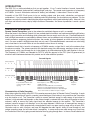
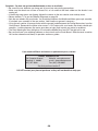
Transmit Signals
Pulse Sequence
•
•
•
•
27.9MHz Signal
•
•
•
•
•
•
4 synchronization bursts each
~
~ 1.8ms long with ~
~ 600µs
spacing.
~ 600µs long with
Burst sequence, each ~
~
~ 600µs spacing.
10 bursts for forward; 34 bursts for forward-left;
28 bursts for forward-right; 40 bursts for backward;
46 bursts for backward-left; 52 bursts for backward-right.
Note: some models use different sequence lengths
{
•
{
•
{
Transmitted Signal
Sequence
Repeats
Characteristics of Radio Reception:
Many factors affect the ability of the RCC-7K to receive commands from its Remote Control Transmitter. A weak
battery in the Transmitter will result in a weaker transmitted signal; if the battery is very weak then the Transmitter
may not function at all. The Transmitter’s ability to convert electrical energy to radio energy is best when its
antenna is fully extended and degrades as the antenna length is reduced; the same thing also applies to the car
antenna’s ability to convert the radio signal back into electrical energy for the receiver. The Transmitter’s
antenna transmits energy in all directions so as the range between it and the car is increased less energy is
received at the car. When operated with strong batteries and in an open area the range will be at least 40 ft.
Obstacles such as walls, furniture, and trees will degrade the radio signal’s ability to travel through air and
reduce operating range, but will never block it completely. In some cases more radio energy may travel from
the Transmitter to the car by going around obstacles than by going through them. In the car, weak batteries will
-3-
reduce power to the Motor and degrade the receiver’s ability to filter, amplify, and decode commands from the
Transmitter.
Radio Receiver: (refer to the schematics and block diagram on p.31 as needed)
The car antenna collects radio energy and converts it back into electrical energy; the energy here will always
be much less than the energy originally applied to the transmitting antenna. If the car is turned on then the radio
receiver in the car is continuously monitoring the electrical energy from its antenna. The first stage of the
receiver is basically a filter which is tuned to amplify any energy around 27.9MHz and block energy the antenna
picks up outside this region. If the Remote Control Transmitter is sending commands then its radio signal will
be picked up by the receiver and converted back into the original pulse sequence. Decoding circuitry then
determines which commands were sent by measuring the number of received pulses in the sequence. Signals
are then sent to the motors to execute the commands.
Take a closer look at the receiver schematic. The sub-circuit centered around transistor Q1 filters the antenna
output, if an RCC-7K transmitter is operating nearby then the 27.9MHz burst signal may be visible at its
collector. Inductor L1 is tuned so that the circuit amplifies around 27.9MHz while rejecting all other frequencies.
But we really want the pulse sequence that is hidden in the 27.9MHz signal, so then C10 is used to filter out the
27.9MHz from the burst signal we received. This result is applied to pin 14 of the SCRX2BC integrated circuit.
Inside SCRX2BC the signal is amplified and filtered in two stages between pins 14, 15, 16, 1, and 3. Pin 3 (DI)
is the output pulse sequence that was picked up by the receiver; this is used as the input to the decoder. The
SCRX2BC scans for the 4 long (synchronization) pulses and then counts the number of short pulses after them
to determine which command was sent by the transmitter. The gain of the SCRX2BC stages is high enough to
produce a pulse sequence at pin 3 even if no signal from a transmitter is present (it amplifies random noise),
but the resulting sequence will seldom be identified as one of the transmitter commands. Note from above that
there are 4 long pulses and 10 - 52 short pulses for each command, less pulses could have been used but then
the car is more likely to activate on random noise.
Pins 4 and 5 of SCRX2BC are a 100 kHz (±30%) oscillator that is used as a reference by the decoder.
Car Steering Mechanism: (refer to the schematics on p.31 as needed)
When a command is received to turn left, the SCRX2BC creates a voltage at pin 7 which turns on transistor Q9.
This then turns on Q11 and Q14 and current flows from the batteries through Q11, then through the steering
motor, and then through Q14 to ground. This current through the Motor creates a magnetic field. Inside the
motor is a small magnet which is connected to the gear you see on the outside of the motor. The magnetic field
turns the magnet in the motor, which turns the gear. The “teeth” on the gear grab the Steering Bar and pull it
to one side. Since the Front Wheels are connected to the Steering Bar, the car will turn.
To turn right, the SCRX2BC creates a voltage at pin 6 instead of pin 7. This turns on Q10, Q12, and Q13, and
current flows through the steering motor in the opposite direction. In turn this causes the steering gear, the
steering bar, and the car to turn in the opposite direction.
Car Drive Mechanism: (refer to the schematics as needed)
The Driving Mechanism works the same as the Steering Mechanism. When a command is received to go
forwards the SCRX2BC creates a voltage at pin 11 which turns on Q2. This then turns on Q5 and Q8 and
current flows from the batteries through Q5, then through the driving motor, and then through Q8 to ground.
Similarly to go backwards the voltage is created at pin 10, and Q3, Q6, and Q7 are turned on. The small gear
on the Motor drives the Middle Gear, which drives the gear on the rear wheels axle, making the wheels move.
Note that the gears on the Motor and the rear wheels axle rotate forward and the Middle Gear rotates backward
to drive the car forward, this is because interlocking gears spin in opposite directions. Also notice that between
the Motor gear and the Middle Gear and again between the Middle Gear and the Rear Wheels axle gear, the
number of “teeth” is increased by 4:1 and 5:1 respectively, for 20:1 overall. The Motor must rotate 20 times to
rotate the rear wheels once. The reason for this is that if the Motor were to drive the wheels directly then the
RCC-7K would be very hard to control.
-4-
CONSTRUCTION
Introduction
Assembly of your RCC-7K R/C Car Kit will prove to be an exciting project and give you much satisfaction and personal achievement. If
you have experience in soldering and wiring techniques, then you should have no problem with the assembly of this kit. Care must be
given to identifying the proper components and in good soldering habits. Above all, take your time and follow these easy step-by-step
instructions. Remember, “An ounce of prevention is worth a pound of cure”. Avoid making mistakes and no problems will occur.
CAUTION: WEAR SAFETY GLASSES WHEN ASSEMBLING THIS KIT.
Assemble Components
In all of the following assembly steps, the components must be installed on the top side of the PC board unless otherwise indicated. The
top legend shows where each component goes. The leads pass through the corresponding holes and the board is turned to solder the
component leads on the foil side. Solder immediately unless the pad is adjacent to another hole which will interfere with the placement
of the other component. Cut excessive leads with a diagonal cutter. Then, place a check mark in the box provided next to each step to
indicate that the step is completed. Be sure to save the extra leads for use as jumper wires if needed.
Foil Side
Rx - 100Ω 5% 1/4W Resistor
(brown-black-brown-gold)
Mount Part
Bend Leads to Hold Part
Solder and Cut Off Leads
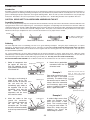
Soldering
The most important factor in assembling your R/C Car is good soldering techniques. Using the proper soldering iron is of prime
importance. A small pencil type soldering iron of 25 - 40 watts is recommended. The tip of the iron must be kept clean at all times
and well tinned. Many areas on the PC board are close together and care must be given not to form solder shorts. Size and care of
the tip will eliminate problems.
For a good soldering job, the areas being soldered must be heated sufficiently so that the solder flows freely. Apply the solder
simultaneously to the component lead and the component pad on the PC board so that good solder flow will occur. Be sure that the
lead extends through the solder smoothly indicating a good solder joint. Use only rosin core solder of 60/40 alloy.
DO NOT USE ACID CORE SOLDER! Do not blob the solder over the lead because this can result in a cold solder joint.
1.
Solder all components from
the copper foil side only.
Push the soldering iron tip
against both the lead and the
circuit board foil.
Soldering Iron
4.
Component Lead
Foil
Here is what a good solder
connection looks like. Cut
off excess leads.
Example 1
Circuit Board
2.
3.
First apply a small amount of
solder to the iron tip. This
allows the heat to leave the
iron and onto the foil.
Immediately apply solder to
the opposite side of the
connection, away from the
iron.
Allow the heated
component and the circuit
foil to melt the solder.
Allow the solder to flow
around the connection.
Then, remove the solder and
the iron and let the
connection cool. The solder
should have flowed smoothly
and not lump around the wire
lead.
Poor solder connections occur
when the lead is not heated
sufficiently. The solder will not
flow onto the lead as shown. To
correct. reheat the connection
and, if necessary, apply a small
amount of additional solder to
obtain a good connection.
Soldering Iron
Solder
Foil
Example 2
Solder
Soldering Iron
Foil
-5-
A solder bridge occurs when
solder runs between circuit
paths and creates a short
circuit. This is usually caused
by using too much solder. To
correct this, simply drag your
soldering iron across the
solder bridge as shown.
Solder does not flow onto the
lead. A hard rosin bead
surrounds and insulates the
connection.
Poor solder
connection
Soldering iron
positioned incorrectly.
IDENTIFYING CAPACITOR VALUES
Capacitors will be identified by their capacitance value in pF (picofarads) or µF (microfarads). Most capacitors
will have their actual value printed on them. Some capacitors may have their value printed in the following
manner.
Second Digit
Multiplier
First Digit
Multiplier
Tolerance
For the No.
0
1
2
3
Multiply By
1
10
100
1k
The above value is 10 x 1,000 = 10,000pF or .01µF
The letter K indicates a tolerance of +10%
The letter J indicates a tolerance of +5%
4
5
8
10k 100k .01
9
0.1
Note: The letter “R” may be used at times to
signify a decimal point; as in 3R3 = 3.3
IDENTIFYING RESISTOR VALUES
Use the following information as a guide in properly identifying the value of resistors.
BAND 1
1st Digit
Color
Black
Brown
Red
Orange
Yellow
Green
Blue
Violet
Gray
White
Digit
0
1
2
3
4
5
6
7
8
9
BAND 2
2nd Digit
Color
Black
Brown
Red
Orange
Yellow
Green
Blue
Violet
Gray
White
Multiplier
Digit
0
1
2
3
4
5
6
7
8
9
1 2
Color
Multiplier
Black
1
Brown
10
Red
100
Orange
1,000
Yellow
10,000
100,000
Green
Blue
1,000,000
Silver
0.01
Gold
0.1
Resistance
Tolerance
Color
Silver
Gold
Brown
Red
Orange
Green
Blue
Violet
Tolerance
+10%
+5%
+1%
+2%
+3%
+.5%
+.25%
+.1%
Multiplier
Tolerance
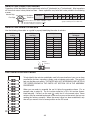
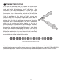
PART IDENTIFICATION CARDS
To help identify the resistors and diodes used in the construction of your car we have
mounted the resistors, capacitors, diodes, and an inductor onto cards. The card will
help you find the parts quickly. THE PARTS WILL NOT NECESSARILY BE LISTED IN
THE ORDER SHOWN IN THE PARTS LIST SECTION OR IN THE ASSEMBLY
PROCEDURE.
When you are ready to assemble the car kit, follow the procedure shown. For an
example refer to page 16. The first resistor called for is R13, 1kΩ resistor (brownblack-red-gold). Locate it on the card ( ), verify that it is the correct value. Some
resistors may be mounted backwards on the card so you must be certain that you are
reading the resistors correctly. When the correct value has been established, only
then will you mount it into its correct position on the PC board.
-6-
ASSEMBLY INSTRUCTIONS
1
Inspection of Parts: Take a look at each of the parts bags and compare to the Parts List (on pages 1 &
2). Be sure that nothing was damaged during shipment and handling. Contact Elenco® Electronics if you
have any problems (phone number is on the back of this manual).
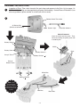
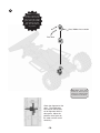
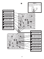
2
Remote Control Transmitter
9V Battery Slot
(Alkaline recommended)
Note: Screw in tight.
Transmitter Antenna
Switch Placement
Insert the switch onto the posts. Then,
secure by melting the plastic posts with
a soldering iron.
Battery Contact,
Switch
Battery Cover
Posts
Battery Contact, +
Snap In Tab
Battery Contact,
+
Back of
Bottom Frame
White Wire
Battery Contacts
+,
NOTE: Slide
the contacts into
the slots and then
fold back the tabs on
the top side to hold
in place.
Red Wire
-7-
Black Wire
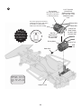
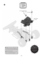
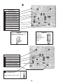
3
Driving Motor
(the larger motor; Yellow
wire goes to tab next to
⊕ marking in plastic)
0.1µF Capacitor
(marked 104):
Solder leads to motor
tabs, one lead is also
soldered to motor
shell.
You cannot get good connections
soldering to the motor shell unless
you first file or scrape away a
small area of the outer coating.
Green Wire
Yellow Wire
⊕
NOTE: If you
have a problem
putting the gear on
the shaft of the motor,
then gently tap the
gear on with a hard
object.
Side Tab:
bend tab back
180O and solder
to motor shell
Driving Motor
⊕
Interior Tab:
Bend Tab 90O,
but don’t short
to motor shell.
Interior Tab
Side
Tab
Motor Gear
Quick Test: Connect a
1.5V battery across the
motor wires with your
hands. The motor should
spin.
Bottom Frame
-8-
4
Rear Wheels
Locators
NOTE: The
next 3 steps will be
much easier if you
elevate the car about
1” using a small
object.
Rear Axle:
the “grip” near the
middle should be
toward the left
Gear for rear axle:
slide on until it is
firmly
in
the
“grips” on the axle
Hard
surface
Note: You may want to use the
method illustrated above to slide the
gear onto the rear axle. Warm the axle
and gear with a heat gun or hairdryer,
then press the gear on carefully using
both thumbs.
Locator Slots
-9-
5
NOTE: Put some
Vaseline or grease into
the slots for the rod and
some on the teeth of all the
gears (motor gear, middle
gear, and the rear axle
gear). This will make the
car go faster.
Gear, Middle of rear section
Rear Rod
Quick Test: All 3 gears
should be lined up and
turning one of them by hand
should also turn the others.
Check the alignment of the
gears. The middle gear
must not be able to slide
out of alignment with the
other gears. Adjust the
positions of the gears on
the motor and rear axle if
necessary.
-10-
Screw Used
(shown actual size)
6
X2
0.4” x 0.1”, 0.15” head
0.4” x 0.1”, 0.15” head
Screws
Rear Section
Cover
NOTE: Make
sure that the wires
from the ON/OFF switch
and the motor run out of
the rear section cover
through the slots (as
shown) without being
damaged.
Quick Test: Lift the wheels off the ground so they
may spin freely. Connect a 1.5V battery across the
motor wires with your hands, (+) terminal to green
wire. The wheels should spin forward slowly but
smoothly. Reverse the wires to the battery and the
wheels should spin backwards.
Note: Try to also press down on the forward part of
the rear cover while doing this, since the forward
screws for it have not been installed yet.
-11-
Bend wires to fit around post.
They must NOT be tight (or the
steering won’t work), stretch
the wire with your fingers to
loosen it if necessary.
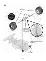
7
Spring for Steering
Centering
Steering
Alignment
Adjustment
post is towards
front of car
front
of car
(triangular piece will
lean against this)
Steering Bar
Between the Wires
After inserting wire on it,
melt the top of this post
with a soldering iron to
keep the spring in place.
Wires
Turning Posts for
front wheels
Front
Wheels
Hammer the
bars into the
wheels, but leave a
small space so that
the turning posts
may spin freely.
Front
Wheel
Bars
Note direction
of post.
-12-
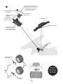
Steering Motor
0.01µF Capacitor
(marked 103):
Solder leads to motor tabs, one lead is
also soldered to motor shell.
(the smaller motor; Blue
wire goes to tab next to
⊕ marking in plastic)
8
You cannot get good
connections soldering to
the motor shell unless
you first file or scrape
away a small area of the
outer coating.
Orange Wire
⊕
⊕
Side Tab:
bend tab back
180O and solder
to motor shell
Screw Used
(shown actual size)
X2
Quick Test: Connect a 1.5V
battery across the motor wires
with your hands - the motor
should spin. Reverse the wires to
the battery and the motor should
spin in the opposite direction.
0.3” x 0.1”,
0.15” head
Screws
NOTE: If you
have a problem
putting the gear on
the shaft of the motor,
then gently tap the
gear on with a hard
object.
0.3” x 0.1”, 0.15” head
NOTE: The
next 3 steps will be
much easier if you
elevate the car about
1” using a small
object.
Left Front Wheel
Blue Wire
Right Front Wheel
Motor Gear
NOTE: The gear
should lay on the
teeth of the steering
bar. Add some
Vaseline or grease to
the teeth.
Quick Test: Turning one
wheel by hand should also
turn the other wheel and
move the gear along the
steering bar.
-13-
9
Front Spring
Front Wheel Shock Absorbers
Post
-14-
10
0.3” x 0.1”, 0.15” head
Screws
Screw Used
(shown actual size)
X2
0.3” x 0.1”, 0.15” head
Front Wheels Section Cover
Quick Test: Install 4 fresh AA alkaline batteries in
the battery cage, observing their polarity while
doing so. Lift the front wheels off the ground so they
may spin freely. Touch the steering motor wires to
the left-front and left-rear battery contacts with your
hands. The front wheels should turn to one side (as
the steering motor gear moves along the steering
bar). Reverse the wires to the batteries and the
wheels should turn in the opposite direction.
-15-
11
ASSEMBLE THE FOLLOWING COMPONENTS TO THE PC BOARD
Review the soldering and parts identification instructions on p.5 at this time. In all of the following steps the
components must be installed on the top legend side of the PC board. The board is turned over to
solder the component leads.
L1 - 9 Turn Inductor (this part
has been pre-tuned, you do not
need to adjust it).
(see Figure A)
R13 - 1kΩ 5% 1/4W Res.
(brown-black-red-gold)
(see Figure B)
R14 - 1kΩ 5% 1/4W Res.
(brown-black-red-gold)
(see Figure B)
D2 - 3V Zener Diode
(see Figure C)
IC1 - 16-pin IC Socket
IC1 - SCRX2BC IC
(see Figure D)
Figure A
Figure D
Figure C
Mount with the band pointing as
shown.
Align the notch on the socket (if any) with
the notch marked on the PC board. Solder
the socket to the PC board. Insert the IC
into the socket with the notch as shown.
Band
Notch
Figure B
Lay resistor flat against the
PC board.
-16-
12
Figure E
Stand resistor on end as shown with the
body inside the white circle (if a white
circle is present).
White
Circle
(see Figure E)
R21 - 560Ω 5% 1/4W Res.
(green-blue-brown-gold)
R10 - 2.7kΩ 5% 1/4W Res.
(red-violet-red-gold)
R4 - 3.3kΩ 5% 1/4W Res.
(orange-orange-red-gold)
R3 - 22kΩ 5% 1/4W Res.
R2 - 22kΩ 5% 1/4W Res.
(red-red-orange-gold)
R3
R1 - 560Ω 5% 1/4W Res.
(green-blue-brown-gold)
R5 - 200Ω 5% 1/4W Res.
(red-black-brown-gold)
R6 - 3.9MΩ 5% 1/4W Res.
R7 - 3.9MΩ 5% 1/4W Res.
(orange-white-green-gold)
(see Figure E)
R11 - 68Ω 5% 1/4W Res.
(blue-gray-black-gold)
R18 - 100Ω 5% 1/4W Res.
R17 - 100Ω 5% 1/4W Res.
R12 - 100Ω 5% 1/4W Res.
(brown-black-brown-gold)
R15 - 1.5kΩ 5% 1/4W Res.
(brown-green-red-gold
R19 - 100Ω 5% 1/4W Res.
R20 - 100Ω 5% 1/4W Res.
(brown-black-brown-gold)
R16 - 1.5kΩ 5% 1/4W Res.
(brown-green-red-gold)
R9 - 200kΩ 5% 1/4W Res.
(red-black-yellow-gold)
R8 - 3.3kΩ 5% 1/4W Res.
(orange-orange-red-gold)
-17-
13
(see Figure F)
C1 - 10pF (10) Capacitor
C10 - 0.01µF (103) Capacitor
C2 - 27pF (27) Capacitor
C3 - 27pF (27) Capacitor
C7 - 0.1µF (104) Capacitor
C8 - 500pF (501) Capacitor
C4 - 3,300pF (332) Capacitor
C9 - 0.01µF (103) Capacitor
C11 - 2,200pF (222) Capacitor
Figure F
Figure G
Mount the ceramic or mylar
capacitor as shown below.
Mount the
electrolytic
capacitor as
shown, noting the
polarity as
shown.
(see Figure G)
C6 - 220µF Lytic Capacitor
C12 - 220µF Lytic Capacitor
C13 - 220µF Lytic Capacitor
C5 - 4.7µF Lytic Capacitor
C14 - 220µF Lytic Capacitor
L2 - 8.2µH 10% Inductor
(gray-red-gold-silver)
Stand inductor on end as shown.
-18-
14
(see Figure H)
Q5 - S8550 Transistor
Q6 - S8550 Transistor
Q8 - S8050 Transistor
Q2 - 9014 Transistor
Q3 - 9014 Transistor
Q7 - S8050 Transistor
Q14 - S8050 Transistor
Q12 - S8550 Transistor
Q9 - 9014 Transistor
Q10 - 9014 Transistor
Q13 - S8050 Transistor
Q11 - S8550 Transistor
Q1 - C945 Transistor
Inspection:
Figure H
Mount the transistor with
the flat side in the same
direction marked on the
PC board.
1/8”
Double check that you have installed all of your parts in
the proper places. Be sure they are not touching each
other and creating short circuits. Inspect all solder
connections and make sure none of them are weak. Use
a magnifying glass if you have one. Check all solder
connections for short circuits. Be thorough as it is much
easier to find and correct problems now rather than later.
-19-
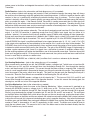
15 TRANSMITTER TESTING
If you have an oscilloscope then you may test the remote control
transmitter for basic operation. Set the scope for 1V/div vertical
scale and 1ms/div horizontal scale. Install a 9V battery in the
transmitter if you haven’t already done so. Connect your scope
probe to the transmitter antenna (leave the probe ground
unconnected), turn on the transmitter, and push the left transmitter
lever. You should see a stream of high-frequency bursts at least
1Vpp in amplitude, of either 0.6ms or 1.8ms duration, and
separated by 0.6ms. (This waveform is described in more detail in
the Theory of Operation section). You will not be able to get a clear
picture due to your lack of a good trigger for your scope - do not be
concerned. Most transmitter problems are due to connections
within the unit breaking loose during shipping, so this test is
primarily testing for the presence of a transmitted signal. Test the 6
transmitter functions: forward, forward-left, forward-right, backward,
backward-left, and backward-right (the 7th function is stop). Note
that on some models the steering lever only works if you are also
pressing the forward/backward lever. The burst patterns are slightly
different for each function, this is not of interest now but is described
in the theory of operation section. If your transmitter does not work
properly then refer to the troubleshooting section.
typical transmitted waveform (not to scale)
If you do not have an oscilloscope but do have a frequency counter, you can run the above test the same way
except instead of seeing a waveform on your scope your counter should measure a signal of 10 MHz to 50 MHz
(the actual frequency is 27.9 MHz but your counter may read differently due to the burst form of the signal).
-20-
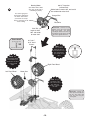
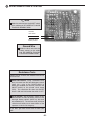
16 INTERCONNECTIONS & TESTING
Vcc Wire
Solder the red wire from the ON/OFF switch
to this solder pad. BE CAREFUL TO AVOID
TOUCHING NEARBY PADS!
Red wire
from switch
Black wire from
battery contact
Ground Wire
Solder the black wire from the
battery contact to this solder
pad. BE CAREFUL TO AVOID
TOUCHING NEARBY PADS!
Resistance Tests
Remove one or all of the “AA” batteries from the car
for these tests.
Switch connections: Using a multimeter set to
ohms, measure from the front-left battery contact
(which has a wire to the ON/OFF switch) to
where you soldered the red wire (also from the
ON/OFF switch) to the printed circuit board
(PCB). This should be 0Ω when the ON/OFF
switch is ON and infinite when the switch is OFF.
Vcc to ground: Set the ON/OFF switch to ON.
Measure from the front-left battery contact to the
front-right battery contact (which has the black
wire soldered to it). The resistance will initially be
<10kΩ but will slowly rise to around 45kΩ as the
capacitors in the circuit charge up.
If you don’t get these results then re-check your
work.
-21-
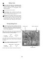
Battery Tests
17
Install 4 fresh AA alkaline (or rechargeable nickelcadmium) batteries in the battery cage, observing their
polarity while doing so. Caution: Do not mix alkaline,
standard (carbon-zinc), or rechargeable (nickelcadmium) batteries.
Snap in the battery cover to close it.
Battery Voltage: Using a multimeter set to DC volts,
measure between the front-left and front-right battery
contacts. You should measure about 6V.
Idle Current: Set the ON/OFF switch to OFF. Set your
multimeter to DC amps. Connect your probes between
the left-front battery tab and the red wire from
connection point 3 on the PCB. You should measure a
current of 18mA ± 8mA. Check your work if you don’t.
Driving Voltage Tests
Set the switch to ON and your multimeter to DC volts.
Connect (–) probe to the front-right battery contact (DC
ground) for all these tests. Activate the transmitter for
forwards/backwards while measuring the voltage at pins
10 & 11 on the SCRX2BC IC.
Q6-Q8 junction
Antenna solder pad
Note: You may need to clip a wire from the antenna on the
remote control unit to the antenna solder pad (next to C1),
since the car’s antenna is not attached yet.
TX: forward
TX: backward
Pin 10
0V
3.0 ± 0.5 V
Pin 11
3.0 ± 0.5 V
0V
If you don’t get these voltages check your receiver and
SCRX2BC support circuitry. Refer to Theory of Operation
as needed.
Similarly, measure the voltages at the Q6-Q8 and Q5Q7 junctions while transmitting commands:
TX: forward
TX: backward
Q6-Q8 junction
0V
6±1V
Q5-Q7 junction
6±1V
0V
Q5-Q7 junction
If you don’t get these voltages, check your driving circuit.
-22-
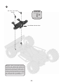
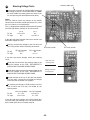
18
Steering Voltage Tests
Antenna solder pad
Activate the transmitter for left/right while measuring
the voltage at pins 6 & 7 on the SCRX2BC IC. (Note:
on some models the steering lever only works if you
are also pressing the forwards/backwards lever).
Notes:
You may need to touch the antenna on the remote
control unit to the antenna solder pad (next to C1), since
the car’s antenna is not attached yet.
The (–) voltage probe should be connected to DC ground
(the front-right battery contact) for all of these tests.
TX: left
TX: right
pin 6
3.0 ± 0.5 V
0V
pin 7
0V
3.0 ± 0.5 V
If you don’t get these voltages check your receiver and
SCRX2BC support circuitry.
Similarly, measure the voltages at the Q12-Q14 and
Q11-Q13 junctions while transmitting commands:
TX: left
TX: right
Q12-Q14 junction
6±1V
0V
Q12-Q14 junction
Q11-Q13 junction
0V
6±1V
If you don’t get these voltages check your steering
circuit.
Solder the blue wire from the steering motor to the
Q12-Q14 junction on the PCB. BE CAREFUL TO
AVOID ALSO TOUCHING NEARBY PADS.
Solder the orange wire from the steering motor to the
Q11-Q13 junction on the PCB. BE CAREFUL TO
AVOID ALSO TOUCHING NEARBY PADS.
Blue wire from
steering motor
Orange wire from
steering motor
Elevate the front of the car so that the front wheels
may turn freely. Activate the transmitter for left/right
and make sure the wheels turn properly.
Re-measure the voltages at PCB junctions Q12-Q14
and Q11-Q13 now that they are loaded by the
steering motor:
TX: left
TX: right
Q12-Q14 (loaded)
5 ± 1.5 V
0.3 ± 0.3 V
Q11-Q13 (loaded)
0.3 ± 0.3 V
5 ± 1.5 V
If you don’t get these voltages or the front wheels don’t
turn then check your steering circuit. You should also redo the motor quick test in assembly step 10.
-23-
Q11-Q13 junction
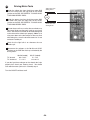
19
Driving Motor Tests
Solder the yellow wire from the driving motor AND
one of the wires from the light bulb to the Q6-Q8
junction on the PCB. BE CAREFUL TO AVOID ALSO
TOUCHING NEARBY PADS..
Solder the green wire from the driving motor AND
the other wire from the light bulb to the Q5-Q7
junction on the PCB. BE CAREFUL TO AVOID ALSO
TOUCHING NEARBY PADS.
Yellow wire from
driving motor
Light
Bulb
Green wire from
driving motor
Elevate the rear of the car so that the rear wheels may
spin freely. Make sure they won’t catch on any of your
wires. Activate the transmitter for forwards/backwards
and make sure the wheels spin properly. Note: Try to
also press down on the forward part of the rear cover
while doing this, since the forward screws for it have
not been installed yet.
Check that the light bulb is on whenever the rear
wheels spin.
Remeasure the voltages at the Q6-Q8 and Q5-Q7
junctions on the PCB now that they are loaded by the
driving motor:
TX: forward
TX: backward
Q6-Q8 (loaded)
0.3 ± 0.3 V
5 ± 1.2 V
Q5-Q7 (loaded)
5 ± 1.2 V
0.3 ± 0.3 V
If you don’t get these voltages or the wheels don’t spin
properly then check your steering circuit. You should
also redo the motor quick test in assembly step 6.
Turn the ON/OFF switches to off.
-24-
20
Light Bulb Cover
Light Bulb
NOTE: Tape
the light bulb wires
to the inside of the
top frame so that the
light bulb stays
above it.
Top Frame
Screw Used
(shown actual size)
X1
0.3” x 0.1”, 0.2” head
Screw
-25-
0.3” x 0.1”, 0.2” head
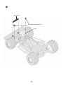
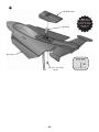
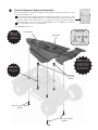
21
Receiver Alignment (highly recommended)
Although tunable inductor L1 has been pre-aligned, you may adjust it for optimum performance. You need
a very small screwdriver for this.
The Car Antenna must be screwed together with the PCB and bottom frame as shown below, to make
a good connection. Flip the ON/OFF switches to on. Activate the transmitter and move it away from the
car. (This is difficult to do by yourself unless you use a rubber band to keep the transmitter activated.)
Adjust tunable inductor L1 for best range. Be VERY GENTLE, since L1 is FRAGILE. It should turn
easily. If you apply too much force you may break it.
Turn the ON/OFF switches to off.
NOTE: Insert
the antenna
through the top
cover before
screwing it down.
Screws Used
Car Antenna
(shown actual size)
Top Frame
X2
0.3” x 0.1”,
0.2” head
X3
0.4” x 0.1”,
0.15” head
NOTE: Be careful
not to stress or break
any of the wires and
connections. You may
also want to tape the
wires down to keep
them inside the car.
NOTE: Orient
the PC board so
that L1 is on the
left side of the
car.
0.3” x 0.1”,
0.2” head
Screws
0.4” x 0.1”, 0.15” head
Screw
0.4” x 0.1”, 0.15” head
Screws
-26-
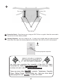
22
Tab
Tab
Tabs
Rear Springs
23
Decorative Decals: Place these on now, using your RCC-7K box as a guide. Note that some models
may not use all of the stickers provided.
24
Steering Alignment: Your car is ready for use. If it does not go straight when you release the right
control lever, then adjust the steering alignment on the bottom front of the car until it works properly.
Front
Steering Alignment Adjustment
You have now completed the assembly of the RCC-7K Radio
Controlled Car. Refer to HOW TO USE IT on the next page. If the
car does not work, refer to TROUBLESHOOTING .
There are many other
projects: Telephones, Cassette
Player, Talking Clocks, AM/FM Radio, etc. Ask your store about
these projects or call
at (847) 541-3800.
-27-
HOW TO USE IT
Place the car in a flat, open area, turn the ON/OFF switches in the car and Remote Control to ON, and extend
the antenna on the Remote Control.
The LEFT lever on the Remote Control:
Push forward (or forward-right) to make the RCC-7K go forward.
Push backward to make the RCC-7K go backward.
Push to center or let go to stop.
The RIGHT lever on the Remote Control:
Push left to make the RCC-7K turn left.
Push right to make the RCC-7K turn right.
Push to center or let go to go straight.
NOTE: The light bulb in the car comes on only when the car is moving forwards or backwards.
The RCC-7K operates best on a wood or tile floor or in your driveway. Never operate the car in the street.
These suggestions will help make your car last for years of fun:
• Never drive your car in rain, snow, mud, sand, dirt, or on a wet floor, as damage may result.
• Do not drive your car on carpet since lint may damage the wheel mechanism.
THE FCC
The Federal Communications Commission (FCC) regulates use of the radio frequency spectrum in the United
States to prevent products from interfering with each other.
FCC regulations for your RCC-7K require you to accept any interference from authorized sources and that you
shut down if you are causing interference with other authorized products. Contact Elenco® Electronics if you
need assistance.
You should never modify the electrical circuit components inside your Remote Control transmitter as this may
cause malfunctions or violate FCC regulations for this product.
-28-
TROUBLESHOOTING GUIDE
Symptom: Car does not go in a straight line when you release the right control lever.
• Adjust the front wheels alignment control on the underside of the Bottom Frame, as you did in assembly
step 24.
Symptom: Car doesn’t work at all.
• Make sure that the batteries in both the car and the Remote Control Transmitter are strong and that they
are installed with the positive and negative terminals positioned properly. Alkaline or rechargeable nickelcadmium batteries are highly recommended, and new ones will last for 30-40 minutes of continuous use.
Do not mix old and new, and and different types of batteries.
• Make sure the ON/OFF switches on both car and transmitter are ON. Note: The light bulb in the car comes
on only when the car is moving forwards or backwards.
• Move the Transmitter antenna close to the car antenna to be sure your range is not degraded. If range is
degraded, see the symptom for reduced range (next).
• Be sure that none of the wiring connections were broken, are contacting any other metal (creating a short
circuit), or are wired wrong.
• Be sure that there is no soldering problems or “short circuits” on the Circuit Board. Use the schematic and
theory of operation section as guides.
• Test the Remote Control Transmitter as in assembly step 15.
Symptom: Car has reduced range.
• Make sure that the batteries in both the car and the Remote Control Transmitter are strong and that they
are installed with the positive and negative terminals positioned properly.
• Make sure your antenna is properly extended.
• Nearby CB and amateur radio transmitters can interfere with your control of the RCC-7K. Try moving away
from them.
• Re-tune inductor T1 as per the Receiver Alignment on page 26.
• Make sure the wire between the Circuit Board and the antenna in the car is intact and that the antenna
screw is tight. Try to verify that the antenna actually touches its metal pad on the circuit board.
• Be sure that there is no solder problems or “short circuits” on the Circuit Board. Use the schematic and
theory of operation section as guides.
Symptom: Car runs even though the Remote Control Transmitter is off.
• Disconnect the battery in your Transmitter to make sure it is not malfunctioning.
• Nearby CB and amateur radio transmitters are interfering with your control of the RCC-7K. Try moving away
from them.
Symptom: Transmitter fails the transmitter test.
• Check that the 9V battery is installed correctly and that your antenna is screwed in tight.
• Unscrew the 2 screws on the bottom of the unit nearest the battery, and snap off the top. Inspect the
transmitter circuit board for problems and broken wires, since most problems are due to connections
breaking loose during shipping. You may use the schematic and theory of operation section as guides.
Symptom: Front wheels do not turn or barely turn.
• Lift up the front section (to remove friction with the ground) and see if the wheels turn now.
• Be sure the steering motor and turning posts are properly seated, then tighten the screws in the front
section cover and steering motor cover.
• Turn one of the front wheels with your hand and be sure that the other wheel turns in the same direction
and that the Steering Motor Gear is moved along the Front Wheels Steering Bar smoothly.
• Be sure you are pressing both transmitter levers, as per the How To Use It section.
• Check the wiring to the Steering Motor and your assembly of the front section.
• Be sure that there is no soldering problems or short circuits on the Circuit Board. Redo the tests in section
18 Use the schematic and theory of operation section as guides.
-29-
Symptom: Car does not go forwards/backwards or does so erratically.
• Be sure all the car batteries are strong and all your wires make strong connections.
• Make sure the wheels are all free of thread, lint, or hair and that the black rubber on the wheels is not
coming off.
• If the driving motor gears are slipping, tighten the screws for the rear section cover and top cover.
• Retune inductor T1 as per the Receiver Alignment on page 26.
• Spin the rear wheels with your hands. You should feel and hear the Middle and Motor gears spin smoothly,
if not check your assembly of the rear section. Add Vaseline or grease if necessary.
• Lift up the rear section (to remove friction with the ground) and disconnect the Driving Motor wires from the
Circuit Board. Reconnect the Motor wires across a 1.5V battery with your hands, the wheels should spin
smoothly. If nothing happens (the motor gear does not spin) then inspect your motor for problems.
• The Rear Wheels gear must be tight on its rod and the Middle Gear must NOT be tight on its rod.
• Be sure that there is no soldering problems or short circuits on the Circuit Board. Redo the tests in section
19 Use the schematic and theory of operation section as guides.
If you need additional assistance or replacement parts, contact:
Elenco® Electronics, Inc.
150 Carpenter Avenue
Website: www.elenco.com
Wheeling, IL 60090
e-mail: [email protected]
Fax: (847) 520-0085
(847) 541-3800
Say that you have version: I
DO NOT contact your place of purchase as they will not be able to help you.
-30-
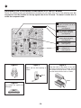
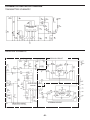
SCHEMATICS AND BLOCK DIAGRAM
TRANSMITTER SCHEMATIC
L
T2
X
Y
PC VDD EC
SCTX2BC
R T1 VSS B
F
TB ENC
RECEIVER SCHEMATIC
(3.1V)
(6V)
YELLOW
(1.1V)
GREEN
SCREW
(2.0V)
DRIVING CIRCUIT
(3.0V)
10pF
(1.8V)
RED
(1.1V)
(1.8V)
(0.8V)
V3
V1 VDD TB
V2
F
B
LX_
R
L
RX_
SCRX2BC
(0.25V)
V4 VSS DI
X
Y
(1.7V)
(1.7V)
(1.7V)
ORANGE
(0.25V)
BLUE
BLACK
STEERING CIRCUIT
RECEIVER CIRCUIT
(VOLTAGES ARE FOR DC IN IDLE MODE)
-31-
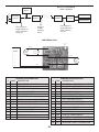
BLOCK DIAGRAM
27.9 MHz
Signal
L
R
F
B
HOW IT WORKS
Driving Motor
Encoding
Circuitry
Filter/
Amplifier
Filter/
Amplifier
Decoding
Circuitry
Steering Motor
Pulse Sequence,
length depends on
which command
was sent
Sequence
of Radio
Frequency
Pulses
Pulse Sequence,
length depends on
which command is
being sent
PCB WIRING PLAN
YELLOW
ON/OFF
Driving
Motor
Light
Bulb
BLUE
GREEN
Steering
Motor
RED
ORANGE
BLACK
SCRX2BC PIN DESCRIPTION
SCTX2BC PIN DESCRIPTION
DESCRIPTION
DESCRIPTION
#
NAME
R
RIGHT STEERING FUNCTION
1
V4
2
T1
TEST USE ONLY
2
VSS
3
VSS
NEGATIVE POWER SUPPLY
3
DI
INPUT PIN OF THE DECODING SIGNAL
4
B
BACKWARD FUNCTION
4
X
OSCILLATOR INPUT
5
F
FORWARD FUNCTION
5
Y
OSCILLATOR OUTPUT
6
TB
DO NOT USE
6
R
RIGHT STEERING OUTPUT
7
ENC
ENCODING SIGNAL (NO CARRIER)
7
L
LEFT STEERING OUTPUT
8
EC
ENCODING SIGNAL (WITH CARRIER)
8
RX_
RIGHT DISABLE (NOT USED)
LEFT DISABLE (NOT USED)
#
NAME
1
INVERTER 2 OUTPUT FOR AMPLIFIER
NEGATIVE POWER SUPPLY
9
VDD
POSITIVE POWER SUPPLY
9
LX_
10
PC
POWER CONTROL OUTPUT
10
B
BACKWARD OUTPUT
11
Y
OSCILLATOR OUTPUT
11
F
FORWARD OUTPUT
12
X
OSCILLATOR INPUT
12
TB
13
T2
TEST USE ONLY
13
VDD
14
L
LEFT STEERING FUNCTION
14
V1
INVERTER 1 INPUT FOR AMPLIFIER
15
V2
INVERTER 1 OUTPUT FOR AMPLIFIER
16
V3
INVERTER 2 INPUT FOR AMPLIFIER
-32-
DO NOT USE
POSITIVE POWER SUPPLY
QUIZ
1. The antenna in the Remote Control Transmitter converts electrical energy into . . . . .
A - radio energy.
B - mechanical energy.
C - geothermal energy.
D - nuclear energy.
2. The commands to be sent from the Remote Control Transmitter are encoded onto a sequence of electrical pulses by
changing . . . . .
A - the spacing between the pulses.
B - the duty cycle of the pulses.
C - the number of pulses in the sequence.
D - the amplitude of the pulses.
3. On some models the Remote Control Transmitter only sends Left/Right commands if Forwards/Backwards commands
are also being sent because . . . . .
A - The left/right lever is not electrically connected to anything.
B - Otherwise the transmitted signal would be too weak to be picked up by the car.
C - Otherwise the transmitter would interfere with your TV reception.
D - there is to much friction to turn the front wheels unless the car is moving.
4. If there is an obstacle between the Transmitter and the car then radio energy can travel to the car by going . . . . .
A - through the obstacle.
B - around the obstacle.
C - both A and B.
D - not possible, the obstacle blocks radio reception completely.
5. If the batteries in the RCC-7K are weak, the main effects you will notice are . . . . .
A - reduced remote control range and reduced power to the motor.
B - the light bulb blinks to tell you to change the batteries.
C - interference with your TV set.
D - the car goes faster.
6. The first stage of the receiver is basically a . . . . .
A - speaker.
B - integrated circuit.
C - power supply.
D - filter.
7. Using less synchronization pulses or less pulses to represent each of the transmitter commands makes . . . . .
A - it take longer to transmit each command.
B - the transmitter battery last a lot longer.
C - the car more likely to activate on random noise.
D - the car go faster.
8. Reversing the voltage to the steering motor will cause . . . . .
A - the motor to explode.
B - the motor and the car to turn in the opposite direction.
C - the motor to spin faster.
D - the motor to stop spinning.
9. Interlocking gears . . . . .
A - spin in the same direction.
B - serve no useful purpose.
C - jam together and prevent each other from spinning.
D - spin in opposite directions.
10. To spin the rear wheels once, the driving motor must spin . . . . .
A - 100 times.
B - 20 times.
C - 9 times.
D - 4 times.
Answers: 1. A, 2. C, 3. D, 4. C, 5. A, 6. D, 7. C, 8. B, 9. D, 10. B
-33-
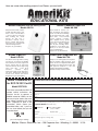
Here are some other exciting projects from Elenco® you can build.
EDUCATIONAL KITS
Motion Detector Kit
Stereo Cassette Player Kit
with training course
Model AK-510
Model AK-200
Simple and fun to build, compact,
portable and adds safety to your
home or office. Learn the basics
of motion detector technology
while building this motion
detector kit that uses a
pyroelectric infrared sensor.
Comes complete with all parts,
PC board, case, schematic and
extensive training manual.
Requires one (1) 9V battery.
Easy-to-build kit teaches you
basic mechanical and electronic
circuits. You will have fun building
this kit and learning how a tape
player works. Lesson manual
teaches magnetic recording,
audio amplifier theory, speed
control, mechanical switching and
much more. Comes complete
with all parts including Stereo
Headphones. Clear plastic case
allows you to show you friends
your accomplishments.
Requires two (2) “AA” batteries.
Strobe Light Kit
Pulse/Tone Telephone Kit
Model AK-520
Model AK-700
This deluxe strobe light makes learning
fun and easy. You will have fun building
this kit and learn how strobe lights work.
Comes complete with all components
and lesson manual. Kit uses high energy
xenon flash tube.
Learn about
transistors,
oscillators,
step-up
transformers, trigger circuits, flash tubes,
and more! Easy-to-follow instructions
include lesson manual and self-test.
Requires two (2) “C” size batteries.
49MHz Conversion Kit
for RCC-7K R/C Car Kit
Model RCC7K49
This kit lets you modify the RCC-7K
remote control transmitter and
receiver circuits to operate at
49MHz instead of 27MHz, so that
two cars may be used at the same
time without interfering with each
other. Replaces 14 parts in the
transmitter (which comes preassembled here) and 7 parts on
the car circuit board (that you will
assemble here).
9.95
$
(plus $4.00 shipping & handling)
Build your own working pulse/tone telephone
with last number redial and ringer on/off
switch. See the neon nights flash through the
transparent case when the phone rings! This
FCC approved telephone is also fully
modular and desk/wall mountable.
Detailed assembly manual included.
PLEASE PRINT OR TYPE WITH COMPLETE INFORMATION
Name (First, Middle Initial, Last)
Street
City, State, Zip
Phone #
Fax #
E-mail
(If you need different shipping and billing addresses, please use a separate sheet.)
Payment Method
We Accept
(U.S. Dollars only)
Credit Card
Check or Money Order
(Sorry, no CODs)
Card Type: ___________
Expiration Date: ___ / ______
Card #: ___________________________________________
Name (as it appears on charge card)
_____________________________________
Signature: _________________________________________
Mail to: Elenco® Electronics, Inc. • 150 Carpenter Ave. • Wheeling, IL 60090
-34-
U.S.A.
Elenco® Electronics, Inc.
150 Carpenter Avenue
Wheeling, IL 60090
(847) 541-3800
Fax: (847) 520-0085
Website: www.elenco.com
E-mail: [email protected]