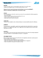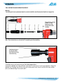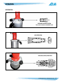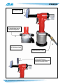
1
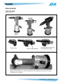
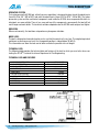
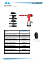
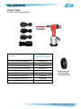
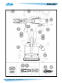
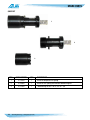
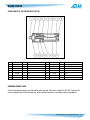
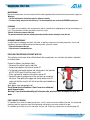
AE 938
HYDRO-PNEUMATIC TOOL
WITH OIL PRESSURE REGULATION
Operating Instructions
FEATURES
NOTE: THE AE 938 TOOL COMES WITHOUT NOSE ASSEMBLY KITS.
NOSE ASSEMBLY KITS HAVE TO BE ORDERED SEPARATELY ACCORDING TO THE USER NEEDS.
1. Air piston return (without spring).
2. Power piston air outwardly, not through the piston.
3. Kit assembly with toothed ring nut (wrench no longer necessary).
4. Tie rods are now replaced by commercial screws.
5. Additional unscrewing in case the user installs the wrong insert, or in case it gets stuck due to an
improper regulation.
6. One position trigger mechanism.
7. No adjustments are needed when there is a thickness change in materials.
8. No damages occurs to mandrel (or tie rod) if operations are repeated.
9. Lightweight.
10. Small dimensions.
2
PennEngineering • www.pemnet.com
FEATURES
RIV938 AND RIV938S
PROTECTIVE WING
(optional accessory)
Protective wing
Remove standard protection
Install the protective wing into the
standard protection housing
Together with the rubber base, it creates a support for the tool, avoiding any contact of the surface with
the metal part of the tool body.
PennEngineering • www.pemnet.com
3
TOOL DESCRIPTION
OPERATING SYSTEM
The hydro-pneumatic AE 938 tool, with oil pressure regulation, is designed to place female threaded inserts
(from #4-40 to 3/8” / M3 to M10) and male threaded inserts (from #8-32 to 5/16” / M4 to M8). The hydropneumatic system and the mechanical components used inside the AE 938, when compared with other riveting tools, are more reliable. There is less wear and tear of the components, consequently the tool will last
much longer and work better. The technical solutions adopted make the AE 938 more compact and lighter.
VIBRATION
When used correctly, the tool does not produce any dangerous vibration.
NOISE LEVEL
The tool is designed and manufactured in such a way that the noise level is very low. The weighed equivalent
continuous acoustic pressure level A in the operator position is indeed below 80 dB (A).
This information can allow the tool user to better evaluate the possible risks of danger.
TECHNICAL DATA
The following table provides the technical data and features of the tool, to which you must refer when contacting the ATLAS® Technical Assistance Department at PennEngineering.
TECHNICAL DATA AND FEATURES
AIR WORKING PRESSURE
MAX AIR PRESSURE
AIR CONSUMPTION PER CYCLE AT 6 BAR
MAX STROKE
MAX FORCE
MOTOR SPEED (SPIN ON)
MOTOR SPEED (SPIN OFF)
WEIGHT
VIBRATIONS
NOISE LEVEL
4
PennEngineering • www.pemnet.com
87 PSI / 6 BAR
70 to 100 PSI / 5 to 7 BAR
5 liter
0.256” / 6.5 mm
19.000 N
1600 rpm
2000 rpm
4 lbs. / 1.8 kg
< 2.5 m/s2
76 dB (A)
TOOL DESCRIPTION
NOSE ASSEMBLIES AND STANDARD ACCESSORIES
The nose assemblies stated hereafter refers to standard tools.
Any special tool could consequently require special parts, different than those listed.
REF.
1
2
3
4
5
6
–
PART NUMBER
4143400
3064400
0369800
0207300
2533800
4154200
–
QTY
1
1
1
1
1
1
1
DESCRIPTION
RIV 938-HYDRO-PNEUMATIC TOOL FOR INSERTS (IN CASE)
HYDRAULIC OIL TYPE ISO VG 32 100CC
PLASTIC CASE
UNIVERSAL KEY
EMERGENCY AND STROKE REGULATION PIN
REGULATION WRENCH MM. 3,0
INSTRUCTION MANUAL
Hook for balancer
Part Number 4229800
PennEngineering • www.pemnet.com
5
TOOL DESCRIPTION
OPTIONAL TOOLING
For Blind Threaded Insert Installation
Nose assembly
screws into here
Description
Part Number For
Complete Nose Assembly
Kit to install #4-40 blind threaded nuts
AE938NP-440
Kit to install #6-32 blind threaded nuts
AE938NP-632
Kit to install #8-32 blind threaded nuts
AE938NP-832
Kit to install #10-32 blind threaded nuts
AE938NP-1032
Kit to install 1/4-20 blind threaded nuts
AE938NP-2520
Kit to install 5/16-18 blind threaded nuts
AE938NP-3118
Kit to install 3/8-16 blind threaded nuts
AE938NP-3716
Kit to install M3 blind threaded nuts
AE938NP-M3
Kit to install M4 blind threaded nuts
AE938NP-M4
Kit to install M5 blind threaded nuts
AE938NP-M5
Kit to install M6 blind threaded nuts
AE938NP-M6
Kit to install M8 blind threaded nuts
AE938NP-M8
Kit to install M10 blind threaded nuts
AE938NP-M10
6
PennEngineering • www.pemnet.com
Head ring nut can be
ordered separately
Part number 0327700
TOOL DESCRIPTION
OPTIONAL TOOLING
For Blind Threaded Stud Installation
Nose assembly
screws into here
Description
Part Number For
Complete Nose Assembly
Kit to install #8-32 blind threaded studs
AE938SNP-832
Kit to install #10-32 blind threaded studs
AE938SNP-1032
Kit to install 1/4-20 blind threaded studs
AE938SNP-2520
Kit to install 5/16-18 blind threaded studs
AE938SNP-3118
Kit to install M4 blind threaded studs
AE938SNP-M4
Kit to install M5 blind threaded studs
AE938SNP-M5
Kit to install M6 blind threaded studs
AE938SNP-M6
Kit to install M8 blind threaded studs
AE938SNP-M8
Head ring nut can be
ordered separately
Part number 0327700
PennEngineering • www.pemnet.com
7
SPARE PARTS
8
PennEngineering • www.pemnet.com
SPARE PARTS
REF.
PART NUMBER
QTY
DESCRIPTION
REF.
PART NUMBER
QTY
DESCRIPTION
1
4153100
1
Handle casing
22
4174200
1
Quick coupling kit
2
3539900
1
Outer cone
23
4177400
1
Gasket kit (3 pieces)
3
4172400
1
Ring nut M3 - M10 / #4-40 - 3/8”
24
4152500
1
Piston, stem, O-ring kit (4 pieces)
4
4165100
1
Rubber base
25
4157300
1
Complete stem guide kit (5 pieces)
5
3098600
1
Ring nut
26
4151000
1
Piston gasket kit (2 pieces)
6
4151500
1
Rotating pin
27
4175700
1
Oil cap kit with washer
7
3093200
1
Snap ring
28
4175600
1
Air hoses kit with O-ring (6 pieces)
8
4151300
1
Oil piston
29
4151100
1
O-ring kit and screws (5 pieces)
9
4151700
1
Spring
30
4152300
1
Flat gasket kit and O-ring
10
4151800
1
Ring nut
31
4151200
1
O-ring kit (4 pieces)
11
4151900
1
Protection
32
4156900
1
Kit complete with O-ring (7 pieces)
12
3761500
1
Motor casing
33
4153400
1
Lever - pin kit
13
3761300
1
Rod
34
3542900
1
Connection thread 1/4” gas plus aluminum washer
14
3096900
1
Ball
35
4157000
1
Kit complete with O-ring (8 pieces)
15
4152800
1
Air body
36
4156600
1
O-ring kit (5 pieces)
16
4152000
1
Dispenser
37
4176600
1
Raffle kit (4 pieces)
17
3762300
1
Bottom
38
4155800
1
O-ring kit (7 pieces)
18
4152100
1
Pin
39
4157100
1
Kit complete with O-ring (13 pieces)
19
3762200
1
O-ring
40
4154400
1
Gasket kit (7 pieces)
20
3761000
1
Motor unit
41
4157200
1
Kit complete (18 pieces)
21
3235600
1
O-ring
PennEngineering • www.pemnet.com
9
SPARE PARTS
QUICK KIT
1
2
3
REF.
1
2
3
10
PART NUMBER
4174200
4176900
4172400
QTY
1
1
1
PennEngineering • www.pemnet.com
DESCRIPTION
Quick kit complete with spring
Quick kit with spring and without toothed ring nut
Toothed ring nut M3 - M10 / #4-40 - 3/8”
SPARE PARTS
SPARE PARTS OF THE MOTOR UNIT (KIT 20)
REF.
PART NUMBER
QTY
1
DESCRIPTION
Planet wheel holder
REF.
PART NUMBER
QTY
DESCRIPTION
3763400
1
22
3327300
1
2
3763300
1Bearing
23
3327400
1Rear plate
Bearing
3
3763200
1Planet wheel
24
3327000
1Stator
4
3327500
1Bearing
25
3326900
1Front plate
5
3523400
1Rotor
26
3763700
1Spacer
6
3327100
1Fin
27
3763600
1Crown wheel
7
3327200
1Roller
28
3763500
1Snap ring
ORDERING SPARE PARTS
Only local authorized dealers are allowed to repair the tool. Otherwise, contact the ATLAS® Technical Assistance Department of PennEngineering, where qualified engineers can help to solve any problems.
PennEngineering • www.pemnet.com
11
SAFETY
GENERAL WARNINGS
The operator must read carefully the information given in the present manual, especially with regard to the safety
precautions listed in this chapter. The operator must also observe the warnings listed below:
• The tool shall be used exclusively by trained personnel.
• The tool and the work area shall be kept clean and tidy.
• The tool shall be rested upright on the rubber base on a flat surface to prevent it from falling.
• The tool shall only be used in normal operating conditions.
• The user shall wear suitable clothing taking care to avoid entanglement of loose parts, ties, long hair, cleaning
rags etc. in the tool itself.
• When using the tool, the operator and others nearby should wear safety glasses to protect against fastener
ejection. We also recommend wearing gloves when using the tool.
• The user shall use the accessories supplied when servicing and/or adjusting the tool.
• Unauthorized personnel shall not be allowed to touch the tool.
• Make sure that the air supply hoses are correctly sized.
• Do not drag the tool holding it by the hose when it is connected to the power supply. Keep the hose away from
sources of heat and from sharp objects.
• Remember to remove service or adjustment keys after having making a repair and/or adjustment.
• Before disconnecting the compressed air hose from the tool, ensure it is not pressurized.
• Air supply must be disconnected before making tool repairs and cleaning.
• When filling with oil, only use fluids with the characteristics indicated herein.
• If you should accidentally spill oil on your skin, rinse and wash thoroughly with soap and water.
• Where possible, you are recommended to use a safety balance to support the tool.
• Pay attention to possible risk of whiplash with the air supply hoses.
• Do not operate the tool when it is directed towards anyone.
INTENDED USE
The tool is designed exclusively to be used with female threaded type inserts and male threaded studs with thread
sizes M3 to M10 / #4-40 to 3/8”.
OPERATION
The tool shall not be used:
• In explosive or aggressive atmosphere or when there is an excessive amount of dust or oil in the air.
• In atmosphere subject to the risk of fire.
• When it is exposed to weather conditions.
RESIDUE RISK
During the normal working cycle and when servicing the tool, the operators are exposed to some residue risks
which, due to the nature of the operations to be carried out, cannot be totally eliminated.
It is therefore absolutely crucial not to exceed the maximum pressure indicated in the technical data section on
page 4.
12
PennEngineering • www.pemnet.com
INSTALLATION
HANDLING
The tool can be hand carried. It is recommended to store the tool in its case after using it.
The tool can be transported safely if is has been correctly put away in its case.
Damages to the tool caused during transport and/or handling are not covered by WARRANTY.
Repairs or replacements of damaged parts are at Customer’s charge.
STORAGE
If you are not going to use the tool for a long time, you must put it away according to the following suggestions:
• Store the tool indoors.
• Protect the tool from impacts and stresses by keeping it in its case.
• Protect the tool from damp and excessive heat.
• Keep the tool away from corrosive substances.
CONNECTIONS
To avoid all sorts of problems when starting the tool you are recommended to observe the following:
PNEUMATIC
The pneumatic line is connected by a quick-release coupling hose to be attached to the air connection,
thread size 1/4”, supplied with the tool. The air supply hose must be flexible and must meet the safety
requirements of the tool.
AIR SUPPLY
The air supply line must be free from dirt and damp to prevent the early wear of the moving components
of the tool. Therefore, it is recommended to use dry air: i.e. not greased.
PRELIMINARY CHECKS
Before putting the tool into service you need to make a few inspections and checks in order to prevent
errors or accidents while starting it.
• Check if the tool has been damaged during transportation.
• Check if the compressed air hose is accurately connected to the air supply line.
• Check if the tool turns freely and if the motor runs freely.
PennEngineering • www.pemnet.com
13
OPERATION
OPERATORS
The tool is designed to be used by one operator only.
Tool operators must satisfy the requirements stated hereafter (or they must be informed and trained accordingly).
They must be aware of the manual herein and of all information relevant to safety:
• They must have some general and technical education, to a sufficient level to be able to understand the manual
and to interpret the drawings and the diagrams correctly.
• They must be acquainted with the safety rules, and with the industrial-safety and technical instructions.
• They must have an overall knowledge of the line and of the factory in which the tool is installed.
• They must know how to act in case of emergency, where to find the individual protection means and how to use
them correctly.
Together with the above-mentioned requirements, the service technicians must also have appropriate technical
training.
MOTOR SCREWING ROTATES NONSTOP
When the rotating pin (6 Part Number 4151500) is broken and you replace it, the motor may rotate
continuously, which means that the shaft (19 Part Number 3761300) is too long; in this case it will have to
be shortened by a few tenths to obtain the closure of the ball (14 Part Number 3096900).
MOTOR UNSCREWING DOES NOT ROTATE
Unlike the situation above, the shaft is too short and it has to be replaced with a new one, fitting it on
the rotating pin (you will have to shorten it) in order to obtain the closure of the ball (14 Part Number
3096900).
14
PennEngineering • www.pemnet.com
OPERATION
TOOL PREPARATION AND SCREW REPLACEMENT
Warning:
Tool setting and screw replacement must be carried out with the tool disconnected from the air supply line.
Ø 1.02” /
26 mm
2.76” /
70 mm
There must be a distance
of .060” / 1.5 mm
between the casing
and the nut for motor
screwing.
Note: These instructions are relevant to KIT assembling and disassembling.
Simultaneously press
the two pins sliding
them into the hole and
unscrew the ring.
To replace screws you have to carry out the following operations:
Unscrew the toothed ring 1 from the tool. Insert joint 2. Insert screw 3. Insert screw adapter 4. Screw the
toothed ring 1 making sure that the screw (or tie rod) moves freely, then try and find the most suitable
joint (see indented ring). Screw on 5 and 6.
PennEngineering • www.pemnet.com
15
OPERATION
Yellow
White
Orange
WARNING!!!
Pressure (force) must
always be regulated as
per maximum thickenss
When screwing and unscrewing,
you will see three rings
(white, yellow, and orange).
OIL (FORCE) PRESSURE REGULATION SETTINGS
M3 / #4-40 -
M3.5 / #6-32 -
M4 / #8-32 -
M5 / #10-32 -
M6 / 1/4-20 -
M8 / 5/16-18 -
M10 / 3/8-16 -
White
White
Yellow
Yellow
Orange
Orange
Orange
Note: These settings are general guidelines to the operator. Inserts are not uniform as hardness and
therefore some modifications may be necessary (+ or -).
16
PennEngineering • www.pemnet.com
OPERATION
INFORMATION
EMERGENCY REVERSE BUTTON
To be used to remove an unsuitable insert
AIR DISTRIBUTOR
PRESSURE (FORCE) REGULATOR
PennEngineering • www.pemnet.com
17
OPERATION
(1) Insert is stuck.
(2) Keep the trigger pressed
and rotate to help loosen.
(3) If this does not work.
(4) Disconnect the air hose.
(5) Insert the Emergency
Regulation Pin in the proper holes,
manually unscrewing the tool.
18
PennEngineering • www.pemnet.com
SERVICING THE TOOL
MAINTENANCE
Maintenance operations must be carried out with the tool stopped and disconnected from the pneumatic supply line.
Warnings:
• The tool maintenance instructions must be followed carefully.
• To ensure safety and perfect tool efficiency, it is recommended to use exclusively ORIGINAL spare parts.
CLEANING
It is a good rule to completely clean and grease the tool on a periodic basis (depending on the type and frequency of
use). These operations must be carried out at least once a year.
Shut-off all sources of power to the tool.
The operator must wear and use suitable personal protections before starting to clean the tool.
ORDINARY MAINTENANCE
In order to prevent stoppages and faults of the tool, an ordinary maintenance (including inspections, checks and
operations) must be scheduled to keep the following under systematic control:
• State of lubrication of the tool.
• State of wear of consumable parts.
REFILLING THE HYDRAULIC CIRCUIT WITH OIL
The hydraulic circuit needs to be refilled with oil after a continuous use, and when you notice a reduction
in the tool stroke.
Proceed as follows (see photo at right):
• Disconnect the airline from the tool inlet.
• Remove cap together with relevant washer 27.
• Put the tool in horizontal position and slowly pour in the hydraulic
oil (ISO VG 32 type) 50 until the circuit is full.
• Screw cap back on, together with relevant washer 27.
• Connect the tool to compressed air line and start up a couple of
idle cycles. Stop pulling the trigger and slowly loosen screw 27;
make sure that the circuit is full with oil and that no air bubbles are
left inside.
Wear gloves when managing the oil.
Do not throw the old oil outdoors. Hand it over to an authorized
waste disposal center.
Warning!: If you should accidentally spill oil on your skin, wash and rinse thoroughly with soap and
water.
PARTS SUBJECT TO WEAR
On a periodic basis check the rubber base for wear, as this is what ensures the stability of the tool. If it should need
replacing, order the spare base from PennEngineering indicating the year/serial number of the tool.
On a periodic basis check the screws and heads for wear and, if necessary, replace them as indicated (page 15).
PennEngineering • www.pemnet.com
19
FAULT DIAGNOSIS AND REPAIRS
REPAIRS
To ensure the operational efficiency and safety of the tool, all repair jobs shall be carried out exclusively by the local
authorized dealer or by the Technical Assistance Service of PennEngineering.
REQUESTING ASSISTANCE
For any information concerning Use, Maintenance, Installation, Repair etc., PennEngineering is at the Customer’s
full disposal for all enquiries.
When making inquiries, the customer is requested to be absolutely clear and to always refer to this Manual.
DISMANTLING INSTRUCTIONS
DISMANTLING INSTRUCTIONS
When disposing the tool you need to separate the plastic parts, which are to be disposed of in compliance with
current Regulations.
As for the bulk metal part of the tool, simply split-up the steel parts from those in other metals or alloys and send to
be melted down and recycled.
The oil drained from the tool must not be thrown outdoors but handed over to an authorized oil disposal center.
ENCLOSED DOCUMENTS
DECLARATION
Declaration of Conformity to DIRECTIVE 2006/42/EC.
20
PennEngineering • www.pemnet.com
©2011
Rev. 311