1
HiSeq® 2500 System
User Guide
FOR RESEARCH USE ONLY
ILLUMINA PROPRIETARY
Part # 15035786 Rev. D
November 2014
Catalog # SY-401-9001DOC
Customize a short end-to-end workflow guide with the Custom Protocol Selector
support.illumina.com/custom-protocol-selector.html
This document and its contents are proprietary to Illumina, Inc. and its affiliates ("Illumina"), and are intended solely for the contractual use of its
customer in connection with the use of the product(s) described herein and for no other purpose. This document and its contents shall not be used or
distributed for any other purpose and/or otherwise communicated, disclosed, or reproduced in any way whatsoever without the prior written
consent of Illumina. Illumina does not convey any license under its patent, trademark, copyright, or common-law rights nor similar rights of any
third parties by this document.
The Software is licensed to you under the terms and conditions of the Illumina Sequencing Software License Agreement in a separate document. If
you do not agree to the terms and conditions therein, Illumina does not license the Software to you, and you should not use or install the Software
The instructions in this document must be strictly and explicitly followed by qualified and properly trained personnel in order to ensure the proper
and safe use of the product(s) described herein. All of the contents of this document must be fully read and understood prior to using such product
(s).
FAILURE TO COMPLETELY READ AND EXPLICITLY FOLLOW ALL OF THE INSTRUCTIONS CONTAINED HEREIN MAY RESULT IN
DAMAGE TO THE PRODUCT(S), INJURY TO PERSONS, INCLUDING TO USERS OR OTHERS, AND DAMAGE TO OTHER PROPERTY.
ILLUMINA DOES NOT ASSUME ANY LIABILITY ARISING OUT OF THE IMPROPER USE OF THE PRODUCT(S) DESCRIBED HEREIN
(INCLUDING PARTS THEREOF OR SOFTWARE) OR ANY USE OF SUCH PRODUCT(S) OUTSIDE THE SCOPE OF THE EXPRESS WRITTEN
LICENSES OR PERMISSIONS GRANTED BY ILLUMINA IN CONNECTION WITH CUSTOMER'S ACQUISITION OF SUCH PRODUCT(S).
FOR RESEARCH USE ONLY
© 2012–2014 Illumina, Inc. All rights reserved.
Illumina, 24sure, BaseSpace, BeadArray, BlueFish, BlueFuse, BlueGnome, cBot, CSPro, CytoChip, DesignStudio, Epicentre, GAIIx, Genetic
Energy, Genome Analyzer, GenomeStudio, GoldenGate, HiScan, HiSeq, HiSeq X, Infinium, iScan, iSelect, ForenSeq, MiSeq, MiSeqDx,
MiSeq FGx, NeoPrep, Nextera, NextBio, NextSeq, Powered by Illumina, SeqMonitor, SureMDA, TruGenome, TruSeq, TruSight, Understand
Your Genome, UYG, VeraCode, verifi, VeriSeq, the pumpkin orange color, and the streaming bases design are trademarks of Illumina, Inc. and/or
its affiliate(s) in the U.S. and/or other countries. All other names, logos, and other trademarks are the property of their respective owners.
This software contains the SeqAn Library, which is licensed to Illumina and distributed under the following license:
Copyright © 2010, Knut Reinert, FU Berlin, All rights reserved. Redistribution and use in source and binary forms, with or without modification,
are permitted provided that the following conditions are met:
1
Redistributions of source code must retain the above copyright notice, this list of conditions and the following disclaimer.
2
Redistributions in binary form must reproduce the above copyright notice, this list of conditions and the following disclaimer in the
3
Neither the name of the FU Berlin or Knut Reinert nor the names of its contributors may be used to endorse or promote products derived
documentation and/or other materials provided with the distribution.
from this software without specific prior written permission.
THIS SOFTWARE IS PROVIDED BY THE COPYRIGHT HOLDERS AND CONTRIBUTORS "AS IS" AND ANY EXPRESS OR IMPLIED
WARRANTIES, INCLUDING, BUT NOT LIMITED TO, THE IMPLIED WARRANTIES OF MERCHANTABILITY AND FITNESS FOR A
PARTICULAR PURPOSE ARE DISCLAIMED. IN NO EVENT SHALL THE COPYRIGHT HOLDER OR CONTRIBUTORS BE LIABLE FOR ANY
DIRECT, INDIRECT, INCIDENTAL, SPECIAL, EXEMPLARY, OR CONSEQUENTIAL DAMAGES (INCLUDING, BUT NOT LIMITED TO,
PROCUREMENT OF SUBSTITUTE GOODS OR SERVICES; LOSS OF USE, DATA, OR PROFITS; OR BUSINESS INTERRUPTION) HOWEVER
CAUSED AND ON ANY THEORY OF LIABILITY, WHETHER IN CONTRACT, STRICT LIABILITY, OR TORT (INCLUDING NEGLIGENCE OR
OTHERWISE) ARISING IN ANY WAY OUT OF THE USE OF THIS SOFTWARE, EVEN IF ADVISED OF THE POSSIBILITY OF SUCH DAMAGE.
Read Before Using this Product
This Product, and its use and disposition, is subject to the following terms and conditions. If Purchaser does not agree to these
terms and conditions then Purchaser is not authorized by Illumina to use this Product and Purchaser must not use this Product.
ii
Part # 15035786 Rev. D
1
Definitions. "Application Specific IP" means Illumina owned or controlled intellectual property rights that pertain to
this Product (and use thereof) only with regard to specific field(s) or specific application(s). Application Specific IP
excludes all Illumina owned or controlled intellectual property that cover aspects or features of this Product (or use
thereof) that are common to this Product in all possible applications and all possible fields of use (the "Core IP").
Application Specific IP and Core IP are separate, non-overlapping, subsets of all Illumina owned or controlled intellectual
property. By way of non-limiting example, Illumina intellectual property rights for specific diagnostic methods, for
specific forensic methods, or for specific nucleic acid biomarkers, sequences, or combinations of biomarkers or
sequences are examples of Application Specific IP. "Consumable(s)" means Illumina branded reagents and consumable
items that are intended by Illumina for use with, and are to be consumed through the use of, Hardware.
"Documentation" means Illumina's user manual for this Product, including without limitation, package inserts, and any
other documentation that accompany this Product or that are referenced by the Product or in the packaging for the Product
in effect on the date of shipment from Illumina. Documentation includes this document. "Hardware" means Illumina
branded instruments, accessories or peripherals. "Illumina" means Illumina, Inc. or an Illumina affiliate, as applicable.
"Product" means the product that this document accompanies (e.g., Hardware, Consumables, or Software). "Purchaser"
is the person or entity that rightfully and legally acquires this Product from Illumina or an Illumina authorized dealer.
"Software" means Illumina branded software (e.g., Hardware operating software, data analysis software). All Software is
licensed and not sold and may be subject to additional terms found in the Software's end user license agreement.
"Specifications" means Illumina's written specifications for this Product in effect on the date that the Product ships from
Illumina.
2
Research Use Only Rights. Subject to these terms and conditions and unless otherwise agreed upon in writing by an
officer of Illumina, Purchaser is granted only a non-exclusive, non-transferable, personal, non-sublicensable right under
Illumina's Core IP, in existence on the date that this Product ships from Illumina, solely to use this Product in Purchaser's
facility for Purchaser's internal research purposes (which includes research services provided to third parties) and solely
in accordance with this Product's Documentation, but specifically excluding any use that (a) would require rights or a
license from Illumina to Application Specific IP, (b) is a re-use of a previously used Consumable, (c) is the disassembling,
reverse-engineering, reverse-compiling, or reverse-assembling of this Product, (d) is the separation, extraction, or
isolation of components of this Product or other unauthorized analysis of this Product, (e) gains access to or determines
the methods of operation of this Product, (f) is the use of non-Illumina reagent/consumables with Illumina's Hardware
(does not apply if the Specifications or Documentation state otherwise), or (g) is the transfer to a third-party of, or sublicensing of, Software or any third-party software. All Software, whether provided separately, installed on, or embedded
in a Product, is licensed to Purchaser and not sold. Except as expressly stated in this Section, no right or license under
any of Illumina's intellectual property rights is or are granted expressly, by implication, or by estoppel.
Purchaser is solely responsible for determining whether Purchaser has all intellectual property rights that are
necessary for Purchaser's intended uses of this Product, including without limitation, any rights from third
parties or rights to Application Specific IP. Illumina makes no guarantee or warranty that purchaser's specific
intended uses will not infringe the intellectual property rights of a third party or Application Specific IP.
3
Regulatory. This Product has not been approved, cleared, or licensed by the United States Food and Drug
Administration or any other regulatory entity whether foreign or domestic for any specific intended use, whether
research, commercial, diagnostic, or otherwise. This Product is labeled For Research Use Only. Purchaser must ensure it
has any regulatory approvals that are necessary for Purchaser's intended uses of this Product.
4
Unauthorized Uses. Purchaser agrees: (a) to use each Consumable only one time, and (b) to use only Illumina
consumables/reagents with Illumina Hardware. The limitations in (a)-(b) do not apply if the Documentation or
Specifications for this Product state otherwise. Purchaser agrees not to, nor authorize any third party to, engage in any of
the following activities: (i) disassemble, reverse-engineer, reverse-compile, or reverse-assemble the Product, (ii) separate,
extract, or isolate components of this Product or subject this Product or components thereof to any analysis not expressly
authorized in this Product's Documentation, (iii) gain access to or attempt to determine the methods of operation of this
HiSeq 2500 System User Guide
iii
Product, or (iv) transfer to a third-party, or grant a sublicense, to any Software or any third-party software. Purchaser
further agrees that the contents of and methods of operation of this Product are proprietary to Illumina and this Product
contains or embodies trade secrets of Illumina. The conditions and restrictions found in these terms and conditions are
bargained for conditions of sale and therefore control the sale of and use of this Product by Purchaser.
5
Limited Liability. TO THE EXTENT PERMITTED BY LAW, IN NO EVENT SHALL ILLUMINA OR ITS
SUPPLIERS BE LIABLE TO PURCHASER OR ANY THIRD PARTY FOR COSTS OF PROCUREMENT OF
SUBSTITUTE PRODUCTS OR SERVICES, LOST PROFITS, DATA OR BUSINESS, OR FOR ANY INDIRECT,
SPECIAL, INCIDENTAL, EXEMPLARY, CONSEQUENTIAL, OR PUNITIVE DAMAGES OF ANY KIND ARISING
OUT OF OR IN CONNECTION WITH, WITHOUT LIMITATION, THE SALE OF THIS PRODUCT, ITS USE,
ILLUMINA'S PERFORMANCE HEREUNDER OR ANY OF THESE TERMS AND CONDITIONS, HOWEVER
ARISING OR CAUSED AND ON ANY THEORY OF LIABILITY (WHETHER IN CONTRACT, TORT
(INCLUDING NEGLIGENCE), STRICT LIABILITY OR OTHERWISE).
6
ILLUMINA'S TOTAL AND CUMULATIVE LIABILITY TO PURCHASER OR ANY THIRD PARTY ARISING OUT
OF OR IN CONNECTION WITH THESE TERMS AND CONDITIONS, INCLUDING WITHOUT LIMITATION,
THIS PRODUCT (INCLUDING USE THEREOF) AND ILLUMINA'S PERFORMANCE HEREUNDER, WHETHER
IN CONTRACT, TORT (INCLUDING NEGLIGENCE), STRICT LIABILITY OR OTHERWISE, SHALL IN NO
EVENT EXCEED THE AMOUNT PAID TO ILLUMINA FOR THIS PRODUCT.
7
Limitations on Illumina Provided Warranties. TO THE EXTENT PERMITTED BY LAW AND SUBJECT TO THE
EXPRESS PRODUCT WARRANTY MADE HEREIN ILLUMINA MAKES NO (AND EXPRESSLY DISCLAIMS
ALL) WARRANTIES, EXPRESS, IMPLIED OR STATUTORY, WITH RESPECT TO THIS PRODUCT,
INCLUDING WITHOUT LIMITATION, ANY IMPLIED WARRANTY OF MERCHANTABILITY, FITNESS FOR A
PARTICULAR PURPOSE, NONINFRINGEMENT, OR ARISING FROM COURSE OF PERFORMANCE,
DEALING, USAGE OR TRADE. WITHOUT LIMITING THE GENERALITY OF THE FOREGOING, ILLUMINA
MAKES NO CLAIM, REPRESENTATION, OR WARRANTY OF ANY KIND AS TO THE UTILITY OF THIS
PRODUCT FOR PURCHASER'S INTENDED USES.
8
Product Warranty. All warranties are personal to the Purchaser and may not be transferred or assigned to a third-party,
including an affiliate of Purchaser. All warranties are facility specific and do not transfer if the Product is moved to
another facility of Purchaser, unless Illumina conducts such move.
a
Warranty for Consumables. Illumina warrants that Consumables, other than custom Consumables, will conform to
their Specifications until the later of (i) 3 months from the date of shipment from Illumina, and (ii) any expiration
date or the end of the shelf-life pre-printed on such Consumable by Illumina, but in no event later than 12 months
from the date of shipment. With respect to custom Consumables (i.e., Consumables made to specifications or
designs made by Purchaser or provided to Illumina by, or on behalf of, Purchaser), Illumina only warrants that the
custom Consumables will be made and tested in accordance with Illumina's standard manufacturing and quality
control processes. Illumina makes no warranty that custom Consumables will work as intended by Purchaser or for
Purchaser's intended uses.
b
Warranty for Hardware. Illumina warrants that Hardware, other than Upgraded Components, will conform to its
Specifications for a period of 12 months after its shipment date from Illumina unless the Hardware includes Illumina
provided installation in which case the warranty period begins on the date of installation or 30 days after the date it
was delivered, whichever occurs first ("Base Hardware Warranty"). "Upgraded Components" means Illumina
provided components, modifications, or enhancements to Hardware that was previously acquired by Purchaser.
Illumina warrants that Upgraded Components will conform to their Specifications for a period of 90 days from the
date the Upgraded Components are installed. Upgraded Components do not extend the warranty for the Hardware
unless the upgrade was conducted by Illumina at Illumina's facilities in which case the upgraded Hardware shipped
to Purchaser comes with a Base Hardware Warranty.
iv
Part # 15035786 Rev. D
c
d
e
f
9
Exclusions from Warranty Coverage. The foregoing warranties do not apply to the extent a non-conformance is
due to (i) abuse, misuse, neglect, negligence, accident, improper storage, or use contrary to the Documentation or
Specifications, (ii) improper handling, installation, maintenance, or repair (other than if performed by Illumina's
personnel), (iii) unauthorized alterations, (iv) Force Majeure events, or (v) use with a third party's good not provided
by Illumina (unless the Product's Documentation or Specifications expressly state such third party's good is for use
with the Product).
Procedure for Warranty Coverage. In order to be eligible for repair or replacement under this warranty Purchaser
must (i) promptly contact Illumina's support department to report the non-conformance, (ii) cooperate with Illumina
in confirming or diagnosing the non-conformance, and (iii) return this Product, transportation charges prepaid to
Illumina following Illumina's instructions or, if agreed by Illumina and Purchaser, grant Illumina's authorized repair
personnel access to this Product in order to confirm the non-conformance and make repairs.
Sole Remedy under Warranty. Illumina will, at its option, repair or replace non-conforming Product that it
confirms is covered by this warranty. Repaired or replaced Consumables come with a 30-day warranty. Hardware
may be repaired or replaced with functionally equivalent, reconditioned, or new Hardware or components (if only a
component of Hardware is non-conforming). If the Hardware is replaced in its entirety, the warranty period for the
replacement is 90 days from the date of shipment or the remaining period on the original Hardware warranty,
whichever is shorter. If only a component is being repaired or replaced, the warranty period for such component is
90 days from the date of shipment or the remaining period on the original Hardware warranty, whichever ends later.
The preceding states Purchaser's sole remedy and Illumina's sole obligations under the warranty provided
hereunder.
Third-Party Goods and Warranty. Illumina has no warranty obligations with respect to any goods originating
from a third party and supplied to Purchaser hereunder. Third-party goods are those that are labeled or branded
with a third-party's name. The warranty for third-party goods, if any, is provided by the original manufacturer.
Upon written request Illumina will attempt to pass through any such warranty to Purchaser.
Indemnification.
a
Infringement Indemnification by Illumina. Subject to these terms and conditions, including without limitation,
the Exclusions to Illumina's Indemnification Obligations (Section 9(b) below), the Conditions to Indemnification
Obligations (Section 9(d) below), Illumina shall (i) defend, indemnify and hold harmless Purchaser against any
third-party claim or action alleging that this Product when used for research use purposes, in accordance with these
terms and conditions, and in accordance with this Product's Documentation and Specifications infringes the valid
and enforceable intellectual property rights of a third party, and (ii) pay all settlements entered into, and all final
judgments and costs (including reasonable attorneys' fees) awarded against Purchaser in connection with such
infringement claim. If this Product or any part thereof, becomes, or in Illumina's opinion may become, the subject of
an infringement claim, Illumina shall have the right, at its option, to (A) procure for Purchaser the right to continue
using this Product, (B) modify or replace this Product with a substantially equivalent non-infringing substitute, or
(C) require the return of this Product and terminate the rights, license, and any other permissions provided to
Purchaser with respect this Product and refund to Purchaser the depreciated value (as shown in Purchaser's official
records) of the returned Product at the time of such return; provided that, no refund will be given for used-up or
expired Consumables. This Section states the entire liability of Illumina for any infringement of third party
intellectual property rights.
b
Exclusions to Illumina Indemnification Obligations. Illumina has no obligation to defend, indemnify or hold
harmless Purchaser for any Illumina Infringement Claim to the extent such infringement arises from: (i) the use of
this Product in any manner or for any purpose outside the scope of research use purposes, (ii) the use of this Product
in any manner not in accordance with its Specifications, its Documentation, the rights expressly granted to Purchaser
hereunder, or any breach by Purchaser of these terms and conditions, (iii) the use of this Product in combination
with any other products, materials, or services not supplied by Illumina, (iv) the use of this Product to perform any
assay or other process not supplied by Illumina, or (v) Illumina's compliance with specifications or instructions for
this Product furnished by, or on behalf of, Purchaser (each of (i) – (v), is referred to as an "Excluded Claim").
HiSeq 2500 System User Guide
v
c
d
e
vi
Indemnification by Purchaser. Purchaser shall defend, indemnify and hold harmless Illumina, its affiliates, their
non-affiliate collaborators and development partners that contributed to the development of this Product, and their
respective officers, directors, representatives and employees against any claims, liabilities, damages, fines, penalties,
causes of action, and losses of any and every kind, including without limitation, personal injury or death claims, and
infringement of a third party's intellectual property rights, resulting from, relating to, or arising out of (i) Purchaser's
breach of any of these terms and conditions, (ii) Purchaser's use of this Product outside of the scope of research use
purposes, (iii) any use of this Product not in accordance with this Product's Specifications or Documentation, or (iv)
any Excluded Claim.
Conditions to Indemnification Obligations. The parties' indemnification obligations are conditioned upon the
party seeking indemnification (i) promptly notifying the other party in writing of such claim or action, (ii) giving the
other party exclusive control and authority over the defense and settlement of such claim or action, (iii) not admitting
infringement of any intellectual property right without prior written consent of the other party, (iv) not entering into
any settlement or compromise of any such claim or action without the other party's prior written consent, and (v)
providing reasonable assistance to the other party in the defense of the claim or action; provided that, the party
reimburses the indemnified party for its reasonable out-of-pocket expenses incurred in providing such assistance.
Third-Party Goods and Indemnification. Illumina has no indemnification obligations with respect to any goods
originating from a third party and supplied to Purchaser. Third-party goods are those that are labeled or branded
with a third-party's name. Purchaser's indemnification rights, if any, with respect to third party goods shall be
pursuant to the original manufacturer's or licensor's indemnity. Upon written request Illumina will attempt to pass
through such indemnity, if any, to Purchaser.
Part # 15035786 Rev. D
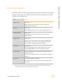
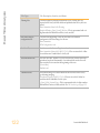
Revision History
Part #
Rev.
Date
15035786
D
November
2014
15035786
C
April 2014
Updated software descriptions to HiSeq Control Software v2.2, which
includes the HiSeq v4 high output mode, removal of the control lane
option, default Q-score binning, and the option to use different indexing
schemes in each lane.
Added the HiSeq v4 workflow for use with HiSeq v4 chemistry.
Added calculation for total SBS priming volume.
15035786
B
November
2013
Removed reagent preparation instructions. For reagent prep instructions
including information about various sequencing primers, see the
documentation for the associated kit.
Replaced the following reagents:
• RMR for RMX
15035786
A
October
2012
HiSeq 2500 System User Guide
Description of Change
Updated Rapid Run mode workflow for compatibility with HiSeq Rapid v2
chemistry.
Replaced NaOH maintenance wash with Tween 20 and ProClin 300
maintenance wash including information about preparing, storing, and
disposing of maintenance wash solution.
Updated descriptions of maintenance wash and water wash to specify that
a water wash is required after a run.
Added workflow, input and output files, error handling, and quality
scoring descriptions to Real-Time Analysis chapter.
Updated VWR catalog # for alcohol wipes to 95041-714.
Updated URL for Safety Data Sheets (SDS) to
support.illumina.com/sds.html.
Initial release.
vii
viii
Part # 15035786 Rev. D
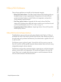
Table of Contents
Revision History
Table of Contents
Chapter 1 Overview
Introduction
HiSeq 2500 Components
Start the HiSeq 2500
HiSeq 2500 Software
Available Disk Space
Sample Sheet Overview
Sequencing Consumables
Additional Resources
Chapter 2 Perform a HiSeq v4 Run
vii
ix
1
2
3
6
7
12
13
14
16
17
Introduction
HiSeq v4 Sequencing Workflow
Run Types for HiSeq v4 Chemistry
Enter Run Parameters
Load and Prime Reagents
Load a Flow Cell
Monitor the Run
18
19
20
21
26
35
40
Chapter 3 Perform a TruSeq v3 Run
41
Introduction
TruSeq v3 Sequencing Workflow
Run Types for TruSeq v3 Chemistry
Enter Run Parameters
Load and Prime Reagents
Load a Flow Cell
Monitor the Run
Prepare Reagents for Read 2
Load Reagents for Read 2
42
43
45
46
51
59
64
65
66
Chapter 4 Perform a Rapid Run
HiSeq 2500 System User Guide
69
ix
Introduction
Rapid Run Sequencing Workflow
Run Types for Rapid Run Chemistry
Pre-Run Volume Check
Enter Run Parameters
Load and Prime Reagents
Load a Flow Cell
Monitor the Run
Chapter 5 Post-Run Procedures
Introduction
Unload and Weigh Reagents
Perform a Maintenance Wash
Perform a Water Wash
Switch Sequencing Modes
Idle the Instrument
Shut Down the Instrument
Chapter 6 Real-Time Analysis
Introduction
Real-Time Analysis Overview
Monitor Run Metrics
Real-Time Analysis Workflow
Sequencing Output Files
Output Folder Structure
Tile Numbering
Thumbnail Images
Chapter 7 Troubleshooting
Introduction
Possible Run Setup Problems
Stagger Runs on Flow Cell A and Flow Cell B
Perform a Fluidics Check
BaseSpace is Unavailable
Stop and Resume a Run
Pause a Run
Primer Rehybridization
70
72
73
75
76
81
90
96
97
98
99
100
104
106
108
109
111
112
113
115
117
121
123
125
126
127
128
129
130
131
132
133
136
137
Index
139
Technical Assistance
143
x
Part # 15035786 Rev. D
Chapter 1 Overview
Introduction
HiSeq 2500 Components
Start the HiSeq 2500
HiSeq 2500 Software
Available Disk Space
Sample Sheet Overview
Sequencing Consumables
Additional Resources
HiSeq 2500 System User Guide
2
3
6
7
12
13
14
16
1
Chapter 1
Overview
Overview
Introduction
The HiSeq® system combines innovative engineering with proven SBS technology to set
new standards in output, simplicity, and cost-effectiveness.
The HiSeq 2500 includes the following features:
} Dual-surface imaging—The HiSeq 2500 uses a 4-camera epifluorescence system with
cutting-edge scanning technology to enable dual surface imaging.
} Dual flow cells—The HiSeq 2500 is a dual flow cell system, which allows sequencing
of a single flow cell or 2 flow cells with different read lengths simultaneously.
} On-instrument cluster generation—The HiSeq 2500 provides the option of Rapid Run
mode, which includes on-instrument cluster generation.
} High-capacity reagent chiller—The reagent compartment is a high-capacity chiller that
holds enough reagents for the entire sequencing run.
} Integrated fluidics for paired-end runs—Integrated paired-end fluidics provide
reagents from the reagent compartment to the flow cell for Read 2 resynthesis and for
indexed sequencing.
} Interface control options—The instrument software interface provides options for
setting up a run and operating the instrument using the touch screen monitor or the
integrated keyboard.
} Real-time base calling—The instrument software extracts intensities from images and
performs quality-scored base calling on the instrument computer, which allows
monitoring of quality metrics during the run and saves time during subsequent data
analysis.
Downstream analysis of sequencing data can be performed with Illumina analysis
software or third-party software on IlluminaCompute, Illumina BaseSpace, or a custom
infrastructure.
} BaseSpace connectivity—The HiSeq 2500 features an option to send instrument health
and sequencing data to the BaseSpace genomics cloud solution in real time to
streamline instrument quality control and analysis.
2
Part # 15035786 Rev. D
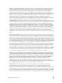
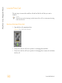
The HiSeq 2500 system comprises the instrument, monitor, instrument control computer,
and accessories, such as a keyboard, mouse, and barcode scanner. The instrument includes
4 main compartments: the optics module, flow cell compartment, fluidics compartment,
and reagents compartment. Instrument operating status is indicated on an illuminated
status bar.
Figure 1 External Components
A
B
C
D
Optics module—Contains optical components that enable dual surface imaging of the
flow cell, imaging A, C, G, and T at the same time using epifluorescence. The excitation
laser beam passes through the objective and the fluorescence is collected through the
same objective.
Flow cell compartment and library loading station—Contains the vacuum-controlled
flow cell stage, which holds the flow cell in place during sequencing runs. Using Rapid
Run mode, the loading station transfers libraries to the flow cell for on-instrument
cluster generation.
Fluidics compartment—Contains fluidics pumps that deliver reagents to the flow cell,
and then to the waste container.
Status bar—Uses 3 colors to indicate instrument status. Blue indicates that the
instrument is running, orange indicates that the instrument needs attention, and green
indicates that the instrument is ready to begin the next run.
HiSeq 2500 System User Guide
3
HiSeq 2500 Components
HiSeq 2500 Components
Overview
E
Reagent compartment—Contains reagent racks that hold reagents for sequencing runs
and wash solution for instrument washes.
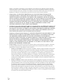
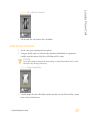
Reagent Compartment
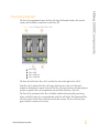
The reagent compartment is a high-capacity reagent chiller that holds 3 reagent racks: 2 for
SBS reagents and 1 for clustering, indexing, and paired-end reagents. Sipper handles lower
the sippers into the reagent bottles.
} SBS reagent racks—Hold 250 ml conical bottles. The reagent rack for flow cell A is
located in the center position, and the rack for flow cell B is located in the far right
position. Each reagent rack has numbered positions that correspond to connections on
an internal reagent selector valve.
} Clustering, indexing, and paired-end reagent rack—Located to the left of racks A and
B. It has 2 rows of numbered positions that hold 15 ml conical tubes containing cluster
and paired-end reagents and indexing reagents. The left row is for flow cell A, and the
right row is for flow cell B.
} Reagent chiller—The reagent chiller houses the reagent racks and maintains an
internal temperature of 2°C to 8°C.
Figure 2 Reagent Compartment
A
B
C
D
4
Sipper handles
Reagent rack for clustering, indexing, and paired-end reagents
Reagent rack for SBS reagents for flow cell A
Reagent rack for SBS reagents for flow cell B
Part # 15035786 Rev. D
HiSeq 2500 Components
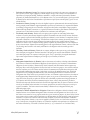
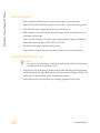
Flow Cell Compartment
The flow cell compartment houses the flow cell stage, the thermal stations, the vacuum
system, and the fluidics connections to each flow cell.
Figure 3 Flow Cell Stage With 2 Flow Cells
A
B
C
D
Flow cell A
Flow cell B
Flow cell lever A
Flow cell lever B
The flow cell on the left is flow cell A, and the flow cell on the right is flow cell B.
Each flow cell is seated on the flow cell stage, which moves in and out of the optics
module as directed by the control software. The flow cell stage must be in the forward-most
position to open the flow cell compartment door and load or remove a flow cell.
The flow cell is positioned on the flow cell holder with the inlet and outlet ports facing
down, and held in place by a vacuum beneath each flow cell holder. The illuminated flow
cell lever in front of each flow cell holder controls the vacuum. The flow cell lever turns
green when the vacuum seal is secure.
HiSeq 2500 System User Guide
5
Overview
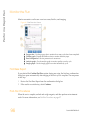
Start the HiSeq 2500
1
Start the instrument control computer.
2
Log on to the operating system using the default user name and password.
• User name: sbsuser
• Password: sbs123
Wait until it has loaded. If the default values do not work, consult your facility
administrator for the site-specific user name and password.
3
Turn on the main power switch to the ON position. When facing the front of the
instrument, the power switch is on the left side.
4
Wait at least 1 minute for the instrument devices to be properly configured and for the
instrument drive called DoNotEject to initialize. A window opens when the drive is
initialized. Close the window. If the window does not open, use MyComputer to check
for the DoNotEject drive.
NOTE
Never eject the DoNotEject flash drive located inside the instrument chassis, or modify the
files on it. This drive contains hardware configuration files and initializes whenever the
instrument is turned on.
5
To ensure adequate disk space, archive the data on the instrument computer from
previous runs to a network location.
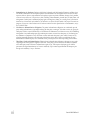
6
Open the HiSeq Control Software (HCS) using the shortcut icon on the computer
desktop. The control software takes a few minutes to initialize. When the software has
initialized, the Mode Select screen opens and the initialization icon
the bottom-right corner of the screen.
appears on
Instrument and Control Computer Best Practices
} Do not turn on the computer while the instrument is running. Always turn on the
computer before turning on the instrument.
} Do not turn off the instrument while the instrument control software is running.
} Wait 1 minute after turning off the instrument before turning it on again.
} Connect the USB cables for the instrument, the monitor, and the keyboard to the back of
the computer before turning on the computer.
} Connect the barcode scanner and mouse to the USB ports on the front of the computer.
6
Part # 15035786 Rev. D
Three software applications are installed on the instrument computer:
} HiSeq 2500 control software—The HiSeq Control Software (HCS) interface guides you
through the steps to set up a sequencing run. During the run, the control software
operates instrument hardware, controls fluidics, sets temperatures, and provides a
visual summary of quality statistics.
} Real-Time Analysis software—Integrated with the control software, Real-Time
Analysis (RTA) performs base calling and assigns a quality score to each base for each
cycle. For more information, see Real-Time Analysis on page 111.
} Sequencing Analysis Viewer software—Sequencing Analysis Viewer (SAV) provides
detailed quality statistics.
HiSeq 2500 Control Software Interface
The Mode Select screen provides run mode options. Modes include TruSeq v3, HiSeq v4,
and Rapid Run. Select a run mode to proceed to the Welcome screen. Because only runs of
the same mode can be performed simultaneously, the selected mode is applied to flow cell
A and flow cell B.
The Welcome screen is split into 2 panels, 1 for each flow cell. You can set up a run for
flow cell A and flow cell B in parallel using the software interface. Runs can also be set up
independently using the software interface.
The Welcome screen provides commands to begin a sequencing run, wash the instrument,
perform a system check, and change modes. The current mode appears at the top of the
screen. When a run is complete, the software prompts to wash the instrument. After the
wash, the software returns to the Welcome screen.
HiSeq 2500 System User Guide
7
HiSeq 2500 Software
HiSeq 2500 Software
Overview
Figure 4 Welcome Screen
A
B
C
D
Welcome screen menu button
Interface panel for flow cell A
Interface panel for flow cell B
Activity indicators
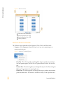
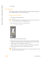
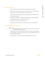
Welcome Screen Commands
The Welcome screen commands include Sequence, Wash, Check, and Mode Select.
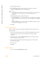
} Sequence—Select Sequence to begin the steps to set up a new sequencing run or
resume an existing run.
Figure 5 Sequence Command Options
• New Run—The software guides you through the steps to specify run parameters,
load and prime reagents, load the flow cell, perform fluidics checks, and start the
run.
• Resume Run—The software guides you through the steps to select the existing run
folder and set parameters for resuming the run.
• Rehyb Run—The software guides you through the steps to perform on-instrument
primer rehybridization. This feature is available in HiSeq v4 and Rapid Run only.
8
Part # 15035786 Rev. D
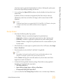
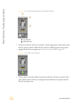
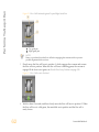
Figure 6 Wash Command Options
• Water Wash—The water wash flushes water through the system. This wash is
required after a sequencing run or after the instrument has been idle for 1 day or
more. See Perform a Water Wash on page 104.
• Maintenance Wash—The maintenance wash flushes Tween 20 and ProClin 300
through the system. This wash is required before switching modes or every 10
days, and is a recommended option after a high output run. See Perform a
Maintenance Wash on page 100.
} Check—Select Check to open the fluidics check screen and confirm proper flow during
instrument installation or fluidics troubleshooting.
} Mode Select—Select Mode Select to change run modes. Run modes include TruSeq v3,
HiSeq v4, and Rapid Run.
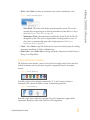
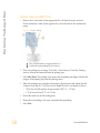
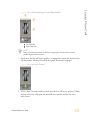
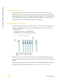
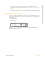
Activity and Sensor Indicators
The Welcome screen contains a series of icons in the lower-right corner of the screen that
indicate instrument activity and status of specific components based on instrument
sensors.
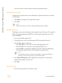
Figure 7 Activity Indicators
From left to right, activity indicators represent the X, Y, and Z motors, electronics
functionality, the camera, the fluidics system, and processing functions.
Figure 8 Sensor Indicators
From left to right, sensor indicators represent flow cell A temperature, reagent chiller
temperature, BaseSpace cloud status, and flow cell B temperature.
HiSeq 2500 System User Guide
9
HiSeq 2500 Software
} Wash—Select Wash to initiate an instrument water wash or maintenance wash.
Overview
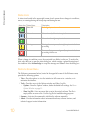
Status Icons
A status icon located in the upper-right corner of each screen shows changes in conditions,
errors, or warnings during run setup steps and during the run.
Status Icon
Status Name
Status OK
Description
No change. System is normal.
Information
Information only. No action is required
Attention
Information that might require attention.
Warning
Warnings do not stop a run, but might require action before
proceeding.
Error
Errors usually stop a run and generally require action before
proceeding with the run.
When a change in condition occurs, the associated icon blinks to alert you. To resolve the
alert, select the icon to open the status dialog box, which contains a general description of
the condition. Select Acknowledge to accept the message and Close to close the dialog box.
Welcome Screen Menu
The Welcome screen menu button, located in the upper-left corner of the Welcome screen,
provides the following options:
} View—Provides options to view the interface in full screen or in a window, or to
minimize the interface.
} Tools—Provides access to the Options window and Show Log file:
• Options—From the Options window, define the default run settings. See Menu
Options Window on page 11.
• Show Log File—Lists any errors that occur in the control software. The file is
empty unless an error exists. Use this log file for troubleshooting purposes.
} Scanner—Activates the command to initialize the software manually.
} About—Provides information about instrument hardware, software versions, and
technical support contact information.
10
Part # 15035786 Rev. D
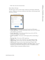
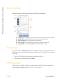
Menu Options Window
The Menu Options window provides settings to define the run ID template, default folder
locations, a LIMS server, user name, and password, and whether to send instrument health
information to Illumina.
Figure 9 Menu Options Window
} Run ID Template—The naming convention used to generate run folder names.
} Default Output Folder—The default output folder for runs on flow cell A. This location
can be changed on a per run basis.
} Default Output Folder2—The default output folder for runs on flow cell B. This
location can be changed on a per run basis.
} Default Temp Folder1—The location to which temporary files are written during a
run.
} Run Setup Folder—The location of LIMS sample forms.
} LIMS Server—The server name for interactions with supported Illumina LIMS.
} LIMS User Name—The user name used when authenticating to Illumina LIMS.
} LIMS Password—The password used when authenticating to Illumina LIMS.
} Send instrument health information to Illumina to aid technical support—Permits the
instrument to send information to BaseSpace for each run. All information remains
confidential. Illumina recommends enabling this feature.
HiSeq 2500 System User Guide
11
HiSeq 2500 Software
} Exit—Closes the control software interface.
Overview
Available Disk Space
The HiSeq instrument computer has a storage capacity of over 2.7 TB per flow cell. Data
from flow cell A is stored on the D: drive, and data from flow cell B is stored on the E:
drive.
At the end of each imaging cycle for each lane, the software checks available disk space on
the local D: and E: drives. The software does not check the network location during the run.
If disk space drops below the safe threshold, the software pauses the run and places the
flow cell in a safe state.
If disk space becomes low, make disk space available to continue the run. When sufficient
disk space becomes available, the run resumes automatically.
12
Part # 15035786 Rev. D
The sample sheet is a user-generated file in *.csv format that stores information about the
sequencing run. When the run begins, the software copies the sample sheet to the run
folder where it is later used for analysis.
Sample sheets are optional unless you are using BaseSpace to perform data analysis,
performing an indexing run, or planning to monitor demultiplexing performance using
Sequencing Analysis Viewer. Use the Illumina Experiment Manager (IEM) to create a
sample sheet before you start the run.
HiSeq 2500 System User Guide
13
Sample Sheet Overview
Sample Sheet Overview
Overview
Sequencing Consumables
Sequencing on the HiSeq 2500 requires reagents and other consumables provided in
Illumina kits. Required kits depend on the type of run to be performed.
} For HiSeq v4 high output runs, see HiSeq v4 Sequencing Consumables on page 18.
} For TruSeq v3 high output runs, see TruSeq v3 Sequencing Consumables on page 42.
} For Rapid Run, see Rapid Run Sequencing Consumables on page 70.
User-Supplied Consumables
14
Consumable
Tween 20, viscous liquid, 100 ml
Supplier
Sigma-Aldrich, catalog # P7949
ProClin 300, 50 ml
Sigma-Aldrich, catalog # 48912-U
Alcohol wipes,
70% Isopropyl
or
Ethanol, 70%
Centrifuge tubes, 250 ml
VWR, catalog # 95041-714
General lab supplier
Corning, catalog # 430776
Conical tubes, 15 ml
Corning, catalog # 430052
Conical tubes, 50 ml,
self-standing (optional)
Carboy, at least 6 liters
Disposable gloves, powder-free
Lab tissue, low-lint
Corning, catalog # 430921
General lab supplier
General lab supplier
VWR, catalog # 21905-026
Lens paper, 4 x 6 in
Pipette tips, 200 µl
VWR, catalog # 52846-001
General lab supplier
Pipette tips, 1000 µl
General lab supplier
Purpose
Instrument maintenance
wash.
Instrument maintenance
wash.
Cleaning the flow cell and
flow cell stage.
Instrument maintenance
wash and water wash.
Collecting and measuring
waste volumes.
Instrument maintenance
wash and water wash.
Storing flow cells.
Maintenance wash solution.
General use.
Cleaning the flow cell
holder.
Cleaning the flow cell.
Splitting reagent kit
volumes.
Splitting reagent kit
volumes.
Part # 15035786 Rev. D
Water, laboratory-grade,
18 M Ohm
Supplier
McMaster-Carr, catalog #
7003A22
Millipore
Purpose
Removing the flow cell
gaskets.
SBS reagent rack, position 2.
Instrument wash.
Microcentrifuge Tubes for Rapid Run Mode
Consumable
Microcentrifuge tube, 1.5 ml
Microcentrifuge tube, 1.7 ml
HiSeq 2500 System User Guide
Supplier
VWR, catalog # 20170-038, catalog # 20170-650, or catalog #
89000-028
Axygen, catalog # MCT-150-C
VWR, catalog # 20170-575
Axygen, catalog # MCT-175-C
Sorenson BioScience, catalog # 16070
15
Sequencing Consumables
Consumable
Tweezers, square plastic tip
Overview
Additional Resources
The following documentation is available for download from the Illumina website.
Resource
Description
HiSeq 2500, 1500, and 2000 Site
Prep Guide (part # 15006407)
Provides specifications for laboratory space, electrical
requirements, and environmental considerations.
HiSeq Safety and Compliance
Guide (part # 15012614)
Provides information about instrument labeling, compliance
certifications, and safety considerations.
HiSeq Cluster Kit v4 Reagent
Prep Guide (part # 15050104)
Provides a description of cluster kit contents and instructions
for preparing consumables before a sequencing run.
HiSeq Rapid Cluster Kit v2
Reagent Prep Guide (part #
15059131)
Provides a description of rapid cluster kit contents and
instructions for preparing consumables before a rapid
sequencing run.
HiSeq SBS Kit v4 Reagent Prep
Guide (part # 15050108)
Provides a description of SBS kit contents and instructions for
preparing consumables before a sequencing run.
HiSeq Rapid SBS Kit v2 Reagent
Prep Guide (part # 15058772)
Provides a description of rapid SBS kit contents and
instructions for preparing consumables before a rapid
sequencing run.
Denaturing and Diluting
Libraries for the HiSeq and GAIIx
(part # 15050107)
Provides instructions for denaturing and diluting prepared
libraries for a sequencing run, and preparing a PhiX control.
This step applies to most library types.
Visit the HiSeq 2500 support page on the Illumina website for access to documentation,
software downloads, online training, and frequently asked questions.
16
Part # 15035786 Rev. D
Chapter 2 Perform a HiSeq v4 Run
Introduction
HiSeq v4 Sequencing Workflow
Run Types for HiSeq v4 Chemistry
Enter Run Parameters
Load and Prime Reagents
Load a Flow Cell
Monitor the Run
HiSeq 2500 System User Guide
18
19
20
21
26
35
40
17
Chapter 2
Perform a HiSeq v4 Run
Perform a HiSeq v4 Run
Introduction
To perform a HiSeq v4 run on the HiSeq 2500, prepare all reagents for the run and then
follow the software prompts to set up the run. Run setup steps include entering run
parameters, loading and priming reagents, loading the flow cell, and performing a fluidics
check.
Visit the HiSeq 2500 specifications page on the Illumina website for information about run
duration and other performance specifications.
HiSeq v4 Sequencing Consumables
HiSeq v4 Kit Name
Description
HiSeq SBS Kit v4
Contains SBS reagents used on the HiSeq 2500.
HiSeq PE Cluster Kit v4
or
HiSeq SR Cluster Kit v4
Contains clustering reagents used on the cBot and indexing
reagents used on the HiSeq 2500.
The PE version of the cluster kit includes paired-end reagents
used on the HiSeq 2500.
Each cluster kit includes an accessories kit that contains flow cell
gasket replacements and funnel caps for SBS reagent bottles.
Reagent Preparation Steps
Before setting up the run, prepare SBS reagents, indexing reagents, and paired-end reagents,
if applicable.
} For SBS reagent preparation, see the HiSeq SBS Kit v4 Reference Guide (part # 15050108).
} For indexing and paired-end reagent preparation, see the HiSeq Cluster Kit v4 Reference
Guide (part # 15050104).
Prepare all reagents before setting up the run. When prompted by the control software, load
all reagents. When using HiSeq v4 chemistry, there is no need to return to the instrument
during the run to load reagents.
18
Part # 15035786 Rev. D
Prepare reagents for the run. Weigh reagents after preparation.
For reagent preparation information, see Reagent Preparation Steps on page
18.
Using the control software, enter run parameters.
When prompted, load all reagents for the run:
• Load SBS reagents for Read 1 and Read 2.
• For indexed runs, load indexing reagents.
• For paired-end runs, load paired-end reagents.
With a used flow cell on the instrument, confirm proper flow.
Prime SBS reagents and measure priming waste.
Load the clustered flow cell for sequencing. Confirm proper flow.
Start the sequencing run.
[Optional] After cycle 1, inspect the first base report, and then continue
Read 1.
The run continues as specified in run parameters.
When the run is complete, unload and weigh reagents.
Perform an instrument wash.
HiSeq 2500 System User Guide
19
HiSeq v4 Sequencing Workflow
HiSeq v4 Sequencing Workflow
Perform a HiSeq v4 Run
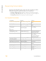
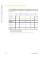
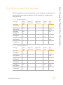
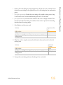
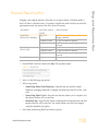
Run Types for HiSeq v4 Chemistry
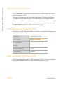
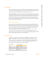
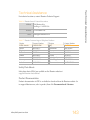
The following table shows types of sequencing runs and the number of possible cycles for
each read when using HiSeq v4 chemistry. Use this information as a reference when setting
up the run.
Run Type
Single-Read,
Non-Indexed
Single-Read,
Single-Indexed
Read 1
Index 1 (i7)
Index 2 (i5)
Read 2
Total
Cycles
≤ 126
Read Cycles
--
Read Cycles
--
Cycles
--
Cycles
≤ 126
≤ 126
--
--
8
--
≤ 133 ¹
≤ 134 ²
≤ 142
Single-Read,
Dual-Indexed
Paired-End,
Non-Indexed
Paired-End,
Single-Indexed
≤ 126
6 or 7 ¹
8²
8
≤ 126
--
--
≤ 126
≤ 252
≤ 126
--
≤ 126
Paired-End,
Dual-Indexed
≤ 126
7¹
8²
8
7+8³
≤ 126
≤ 259 ¹
≤ 260 ²
≤ 275
¹ Number of cycles for single-indexed libraries
² Number of cycles for dual-indexed libraries
³ Index 2 Read of a paired-end dual-indexed run includes 7 additional chemistry-only cycles
20
Part # 15035786 Rev. D
From the Welcome screen, select Sequence | New Run.
The control software interface guides you through the steps to set up the run. Run setup
steps are organized in 3 tabs: Run Configuration, Pre-Run Setup, and Initiate Run.
} Run configuration screens contain drop-down lists, checkboxes, or text fields for run
parameters. Use the hand-held barcode scanner to scan the flow cell or reagent kit ID,
or enter the ID using the touch screen keyboard. The keyboard icon is located to the
right of the text fields.
} Select Next to move to the next screen, or select Back to return to the previous screen.
} At any time during the run setup steps, select Cancel to exit run setup and return to
the Welcome screen.
Integration Screen
The Integration screen provides the option to connect the run to BaseSpace.
To connect to BaseSpace, do the following:
1
Select BaseSpace.
2
Select from the following BaseSpace options:
• Storage and Analysis—Sends run data to BaseSpace for remote monitoring and
data analysis. A sample sheet is required with this option.
• Run Monitoring Only—Sends only InterOp files to BaseSpace, which allows
remote monitoring of the run.
3
Log on to BaseSpace using your MyIllumina account email and password.
4
Select Next.
To proceed without connecting to BaseSpace, do the following:
1
Select None.
2
Select Next.
Storage Screen
1
Select the Save to an output folder checkbox, and select Browse to navigate to a
preferred network location. If the run is connected to BaseSpace for storage and
HiSeq 2500 System User Guide
21
Enter Run Parameters
Enter Run Parameters
Perform a HiSeq v4 Run
analysis, this field is optional.
2
Select Zip BCL files to reduce required storage space. If the run is connected to
BaseSpace, the Zip BCL files option is selected by default.
NOTE
The Bin Q-Scores setting is enabled by default to reduce required storage space. This setting
groups quality scores over a wider range of values without affecting accuracy or
performance.
3
Select from the following Save Auxiliary Files options:
• Save All Thumbnails—Saves all thumbnails images. A thumbnail is a sampling of
images from many tiles in each column of tiles, or swath, combined in 1 thumbnail
image.
• Save Tile Thumbnails—Saves tile thumbnails. Tile thumbnails represent a single
tile rather than a sampling of tiles in a swath.
4
Select Next.
Flow Cell Setup Screen
The Flow Cell Setup screen records information about the flow cell used for the run. All
fields are required.
1
Scan the flow cell barcode or enter the flow cell ID (barcode number) of the flow cell to
be sequenced. The flow cell ID is used to determine flow cell type and reagent
compatibility.
2
Confirm that the flow cell type is HiSeq Flow Cell v4. The flow cell type is selected
automatically based on the flow cell ID.
3
Enter an experiment name. The experiment name appears on each screen to help
identify the run in progress.
4
Enter a user name.
5
Select Next.
Advanced Screen
1
22
[Optional] Select the Confirm First Base checkbox.
Part # 15035786 Rev. D
2
[Optional] From the Align to PhiX checkboxes, clear the checkbox for lanes that do not
contain PhiX.
By default, all lanes are selected for alignment by Real-Time Analysis software.
Alternatively, select lanes on the flow cell image to add or remove lanes for PhiX
alignment.
NOTE
A dedicated control lane is not required with HCS v2.2 and RTA v1.18. Therefore, the option
to assign a control lane is not available with this software configuration.
3
Select Next.
Recipe Screen
1
Select from the following Index Type options:
• No Index—Performs a non-indexed single-read or paired-end run.
• Single Index—Performs a single-read or paired-end run with 1 indexing read.
• Dual Index—Performs a single-read or paired-end run with 2 indexing reads.
• Custom—Performs a single-read or paired-end run with a custom number of cycles
for index reads.
2
If the Dual Index or Custom option is specified, select a Flow Cell Format, either Single
Read or Paired End.
3
Enter the number of cycles for Read 1 and Read 2, if applicable.
NOTE
The number of cycles performed in a read is 1 more cycle than the number of cycles
analyzed. For example, to perform 125 cycles for Read 1, enter 126.
For the Custom indexing option, enter the number of cycles for index reads. Read
lengths do not need to be identical.
4
Confirm the following default chemistry settings. These fields are auto-populated
depending on the selected index type option.
a SBS: HiSeq SBS Kit v4
b Index: HiSeq v4 Single Index or HiSeq v4 Dual Index
c PE turnaround: HiSeq PE Cluster Kit v4
5
[Optional] Select the Use Existing Recipe checkbox to use a custom recipe. Otherwise,
HiSeq 2500 System User Guide
23
Enter Run Parameters
A first base report is generated automatically for each run. Selecting this option opens
the first base report before proceeding with the run.
Perform a HiSeq v4 Run
allow the software to create the recipe from the run parameters entered.
Sample Sheet Screen
Sample sheets are optional unless you use BaseSpace to perform data analysis or perform
an indexed run.
1
Select Browse to navigate to the sample sheet location.
2
Select Next.
NOTE
HiSeq Control Software v2.2 allows a different indexing scheme in each lane.
Reagents Screen
The Reagents screen records information about reagent kits used for the run. The reagent kit
ID (barcode number beginning with RGT) is used to determine reagent kit type and run
mode compatibility.
1
Scan or enter the SBS reagent kit ID.
2
For paired-end runs, scan or enter the reagent kit ID for paired-end cluster kit.
3
Select the SBS reagent kit for the run:
• Select 250 Cycles for a 250 cycle kit. Cycles remaining defaults to 275.
• Select 50 Cycles for a 50 cycle kit. Cycles remaining defaults to 74.
• Select Custom for a partial kit or multiple 50-cycle kits. In the Cycles Remaining
field, enter the number of SBS cycles that reagents are expected to last.
NOTE
For partial kits, the software counts down the number of cycles entered. When the
cycles are low, the software prompts you to load fresh reagents.
4
Select Prime SBS Reagents to prime reagents before starting a run. Always prime
reagents before loading a new flow cell.
5
Select Next.
Review Screen
1
24
Review the run parameters on the Review screen.
Part # 15035786 Rev. D
Enter Run Parameters
2
Select Next to proceed or select Back to change parameters.
HiSeq 2500 System User Guide
25
Perform a HiSeq v4 Run
Load and Prime Reagents
After entering run parameters, load SBS, indexing, and paired-end reagents for the run, and
then prime reagents through the fluidics system. The software guides you through these
steps in a series of screens on the Pre-Run Setup tab.
Illumina-Supplied Consumables
} 8 funnel caps
User-Supplied Consumables
} 250 ml bottle (Corning, catalog # 430776)
} 15 ml conical tubes (Corning, catalog # 430052)
} Laboratory-grade water
NOTE
To prepare for the post-run rinse at the end of a sequencing run, load 25 ml PW1 or
laboratory-grade water in position 2.
The post-run rinse does not replace the post-run instrument wash.
Load SBS Reagents
1
Invert each bottle several times to make sure that the reagents are mixed thoroughly.
2
Remove the cap from each reagent bottle and replace it with a funnel cap.
CAUTION
After handling the bottle of CRM, discard your gloves and replace them with a new pair.
3
Record the weight of each reagent on the lab tracking form.
NOTE
Weighing reagents before and after a sequencing run confirms proper reagent delivery.
26
4
Open the reagent compartment door.
5
Raise the sippers for the sequencing reagent rack using the following motion:
a Pull the handle towards you and then raise the handle.
b Release the sipper handle into the slot on the top end of the groove. Make sure that
the sipper handle rests securely in the slot.
6
Slide the reagent rack out of the reagent compartment.
Part # 15035786 Rev. D
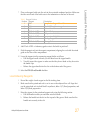
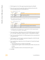
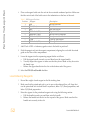
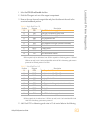
Place each reagent bottle onto the rack in the associated numbered position. Make sure
that the conical end of the bottle rests in the indentation on the base of the rack.
Table 1 Reagent Positions
Position Reagent
1
2
3
4
5
6
7
8
IRM
PW1
USM
SBS Buffer 1 (SB1)
SBS Buffer 2 (SB2)
SBS Buffer 2 (SB2)
CRM
SBS Buffer 3 (SB3)
Description
Incorporation Reagent Master Mix
25 ml of PW1 or laboratory-grade water
Universal Scan Mix
High Salt Buffer
Incorporation Wash Buffer
Incorporation Wash Buffer
Cleavage Reagent Mix
Cleavage Buffer
8
Add 25 ml of PW1 or laboratory-grade water to the bottle in position 2.
9
Slide the reagent rack into the reagent compartment, aligning the rack with the raised
guide on the floor of the compartment.
10 Lower the sippers into the sequencing reagent bottles as follows:
a Pull the sipper handle towards you and then lower the sipper handle.
b Visually inspect the sippers to make sure that they do not bend as they lower into
the funnel caps.
c Release the sipper handle into the slot on the bottom end of the groove.
11 Select the PW1 (25 ml) loaded checkbox.
Load Indexing Reagents
1
Record the weight of each reagent on the lab tracking form.
2
Make sure that the paired-end rack is not in use on the adjacent flow cell. Steps that
use the paired-end rack include Read 2 resynthesis, Index 1 (i7) Read preparation, and
Index 2 (i5) Read preparation.
3
Raise the sippers for the paired-end reagent rack using the following motion:
a Pull the handle towards you and then raise the handle.
b Release the handle into the slot on the top end of the groove. Make sure that the
handle rests securely in the slot.
HiSeq 2500 System User Guide
27
Load and Prime Reagents
7
Perform a HiSeq v4 Run
4
Slide the reagent rack out of the reagent compartment using the rack handle.
5
Remove the caps from each reagent tube and place the tube onto the rack in the
associated numbered position or matching label color.
Table 2 Single-Read Flow Cells
Position
Reagent
15
16
17
FDR
HP9 *
HP12
Description
Fast Denaturation Reagent (contains formamide)
Index Sequencing Primer i5
Index Sequencing Primer i7
* HP9 is required for dual-indexed runs only. If HP9 is not used, load a 15 ml conical tube with 10 ml
laboratory-grade water in position 16.
Table 3 Paired-End Flow Cells
Position
Reagent
10
15
17
FRM *
FDR
HP12
Description
Fast Resynthesis Mix
Fast Denaturation Reagent (contains formamide)
Index Sequencing Primer i7
* Load FRM in position 10 for dual-indexed runs on a paired-end flow cell. FRM is required in position
10 for all paired-end runs regardless of indexing options.
6
If you are performing a single-read run, proceed with the following steps to return the
rack to the reagent compartment. Otherwise, proceed to loading paired-end reagents.
7
Place 15 ml conical tubes filled with 10 ml laboratory-grade water in unused positions
on the paired-end rack.
8
Slide the reagent rack into the reagent compartment, aligning the rack with the raised
guide on the floor of the compartment.
9
If you are performing a single-read run, lower the sippers into the paired-end reagent
tubes as follows:
a Pull the handle towards you and then lower the handle.
b Visually inspect the sippers to make sure that they do not bend as they lower into
the tubes.
c Release the handle into the slot on the bottom end of the groove.
10 Select Next.
28
Part # 15035786 Rev. D
1
Record the weight of each reagent on the lab tracking form.
2
Raise the sippers for the paired-end reagent rack using the following motion:
a Pull the handle towards you and then raise the handle.
b Release the handle into the slot on the top end of the groove. Make sure that the
handle rests securely in the slot.
3
Slide the reagent rack out of the reagent compartment using the rack handle.
4
Remove the caps from each reagent tube and place the tube onto the rack in the
associated numbered position or matching label color.
Table 4 Paired-End Flow Cells
Position
Reagent
10
11
13
14
15
16
FRM *
FLM2
AMS
FPM
FDR *
HP11
Description
Fast Resynthesis Mix
Fast Linearization Mix 2
Fast Amplification Mix
Fast Amplification Premix
Fast Denaturation Reagent (contains formamide)
Read 2 Sequencing Primer
* If you loaded indexing reagents for a single-index run, FDR is already loaded in position 10. If you
loaded indexing reagents for a dual-index run, FRM and FDR are already loaded in positions 10 and
15, respectively.
5
Place 15 ml conical tubes filled with 10 ml laboratory-grade water in unused positions
on the paired-end rack.
6
Slide the reagent rack into the reagent compartment, aligning the rack with the raised
guide on the floor of the compartment.
7
Lower the sippers into the paired-end reagent tubes as follows:
a Pull the handle towards you and then lower the handle.
b Visually inspect the sippers to make sure that they do not bend as they lower into
the tubes.
c Release the handle into the slot on the bottom end of the groove.
8
Select Next.
HiSeq 2500 System User Guide
29
Load and Prime Reagents
Load Paired-End Reagents
Perform a HiSeq v4 Run
Prime Reagents
Steps for priming reagents include cleaning the flow cell holder, loading a priming flow
cell, confirming proper flow, and then starting the prime.
Clean the Flow Cell Holder
1
Open the flow cell compartment door.
CAUTION
Do not place fluids on the flow cell compartment door or on the flow cell stage when the
door is open. Spills in this area can damage the instrument.
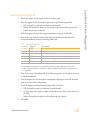
2
Make sure that the flow cell lever is in the OFF position.
Figure 10 Flow Cell Lever in Position 0
3
Put on a new pair of powder-free latex gloves.
4
If the flow cell from a previous run is present, remove it and set aside in a tube of
storage buffer or laboratory-grade water to keep it from drying out. It can be used to
confirm proper flow before loading the clustered flow cell.
5
Using an alcohol wipe or a lint-free tissue moistened with ethanol or isopropanol,
carefully wipe the surface of the flow cell holder until it is clean.
CAUTION
Do not allow alcohol to drip into the vacuum holes or around the manifolds. Use a low-lint
lab tissue to dry the stage, if necessary.
6
30
Visually inspect the flow cell holder to make sure that it is free of lint and the vacuum
holes are free of obstructions.
Part # 15035786 Rev. D
Load a Priming Flow Cell
From the Load Priming Flow Cell screen, load a used flow cell for the priming step. After
loading a used flow cell, confirm that the vacuum is engaged.
NOTE
Illumina recommends using the flow cell from a previous run for priming reagents on a
subsequent run or for a post-run instrument wash.
1
Rinse the used flow cell with laboratory-grade water. Dry the flow cell with a lens
cleaning tissue or lint-free tissue.
2
Clean the flow cell using alcohol wipes and lens cleaning tissue.
NOTE
Do not remove or replace the flow cell gaskets during this step.
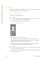
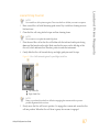
3
Place the used flow cell on the flow cell holder with the inlet and outlet ports facing
down and the barcode on the right. Make sure that the arrow on the left edge of the
flow cell, which indicates flow direction, points towards the instrument.
4
Gently slide the flow cell towards the top and right guide pins until it stops.
NOTE
Remove your hand from the flow cell before engaging the vacuum switch to prevent
possible alignment drift over time.
HiSeq 2500 System User Guide
31
Load and Prime Reagents
Figure 11 Vacuum Hole Locations
Perform a HiSeq v4 Run
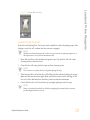
Figure 12 Flow Cell Positioned Against Top and Right Guide Pins
A
B
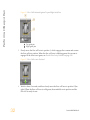
5
Top guide pin
Right guide pins
Slowly move the flow cell lever to position 1, which engages the vacuum and secures
the flow cell into position. When the flow cell lever is blinking green, the vacuum is
engaged. If the lever is not green, see Possible Run Setup Problems on page 129.
Figure 13 Flow Cell Lever in Position 1
6
32
Wait for about 5 seconds, and then slowly move the flow cell lever to position 2 (farright). When the flow cell lever is solid green, the manifolds are in position and the
flow cell is ready for use.
Part # 15035786 Rev. D
7
Make sure that the Vacuum Engaged checkbox is selected on the load prime flow cell
screen, and then select Next.
Confirm Proper Flow
Checking for proper flow confirms that the flow cell and gaskets are properly installed and
the manifold is engaged.
1
Select solution 2 (laboratory-grade water) from the drop-down list.
CAUTION
Use water to confirm proper flow on a used flow cell only. Never use water to confirm
proper flow on a clustered flow cell.
2
Confirm the following default values:
• Volume: 125
• Aspirate Rate: 250
• Dispense Rate: 2000
3
Select Pump.
4
Visually inspect the flow cell for bubbles passing through the lanes and leaks near the
manifolds.
If excessive bubbles are present, check the gaskets for obstructions, reduce the aspirate
rate to 100, and pump another 125 µl of water to the flow cell. If problems persist,
remove the flow cell, repeat the cleaning steps, and reload the flow cell.
HiSeq 2500 System User Guide
33
Load and Prime Reagents
Figure 14 Flow Cell Lever in Position 2
Perform a HiSeq v4 Run
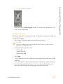
Position Tubing and Start Prime
1
Remove the 8 waste tubes for the appropriate flow cell from the waste container.
Do not include the 8 tubes for the opposite flow cell or the tube for the condensation
pump.
Figure 15 Position Tubing
A
B
34
Flow cell waste tubes for reagent positions 1–8
Condensation pump tubing (do not remove)
2
Place waste tubing into an empty 15 ml tube, 1 waste tube per 15 ml tube. Priming
waste is collected and measured after the priming step.
3
Select Start Prime. The priming screen opens and the priming step begins. Monitor the
progress of the priming step from the priming screen.
4
When the priming step is complete, measure the collected waste and confirm that the
volume in each tube is 1.75 ml for a total of 14 ml. The total is calculated as follows:
• 250 µl for each SBS position except position 2 (250 x 7 = 1.75 ml)
• 1.75 ml for each lane (1.75 x 8 = 14 ml)
5
Record the results on the lab tracking form.
6
Return the waste tubing to the waste container before proceeding.
7
Select Next.
Part # 15035786 Rev. D
Steps to load the clustered flow cell include removing the priming flow cell, cleaning the
flow cell holder, cleaning the flow cell, loading the flow cell, and confirming proper flow.
User-Supplied Consumables
}
}
}
}
Lens cleaning tissue
70% ethanol or alcohol wipes
Low-lint lab tissue
One pair of plastistats
Remove the Used Flow Cell
1
Slowly move the flow cell lever to position 1 to disengage the manifolds.
Figure 16 Flow Cell Lever in Position 1
2
Slowly move the flow cell lever to position 0 to disengage the vacuum seal and release
the flow cell.
HiSeq 2500 System User Guide
35
Load a Flow Cell
Load a Flow Cell
Perform a HiSeq v4 Run
Figure 17 Flow Cell Lever in Position 0
3
Lift the used flow cell from the flow cell holder.
Clean the Flow Cell Holder
1
Put on a new pair of powder-free latex gloves.
2
Using an alcohol wipe or a lint-free tissue moistened with ethanol or isopropanol,
carefully wipe the surface of the flow cell holder until it is clean.
CAUTION
Do not allow alcohol to drip into the vacuum holes or around the manifolds. Use a low-lint
lab tissue to dry the stage, if necessary.
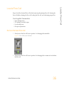
Figure 18 Inspect Vacuum Holes
3
36
Visually inspect the flow cell holder to make sure that it is free of lint and the vacuum
holes are free of obstructions.
Part # 15035786 Rev. D
1
Remove the flow cell from the flow cell container using a pair of plastistats.
2
Rinse the flow cell with laboratory-grade water and dry it with a lens cleaning tissue.
3
Fold an alcohol wipe to approximately the size of the flow cell.
4
Hold the edges of the clustered flow cell with 2 fingers. Make sure that the inlet and
outlet ports are facing up.
5
Wipe each side of the flow cell with a single sweeping motion. Repeat, refolding the
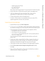
alcohol wipe with each pass, until the flow cell is clean.
6
Dry the flow cell using a dry lens cleaning tissue.
7
Protect the flow cell from dust until you are ready to load it onto the instrument.
Load the Sequencing Flow Cell
NOTE
Do not replace the manifold gaskets. Replace the manifold gaskets after the sequencing run
is complete and before the maintenance wash.
1
Place the flow cell on the flow cell holder with the inlet and outlet ports facing down
and the barcode on the right. Make sure that the arrow on the left edge of the flow cell
points towards the instrument.
2
Gently slide the flow cell towards the top and right guide pins until it stops.
HiSeq 2500 System User Guide
37
Load a Flow Cell
Clean the Flow Cell
Perform a HiSeq v4 Run
Figure 19 Flow Cell Positioned Against Top and Right Guide Pins
A
B
Top guide pin
Right guide pins
NOTE
Remove your hand from the flow cell before engaging the vacuum switch to prevent
possible alignment drift over time.
3
Slowly move the flow cell lever to position 1, which engages the vacuum and secures
the flow cell into position. When the flow cell lever is blinking green, the vacuum is
engaged. If the lever is not green, see Possible Run Setup Problems on page 129.
Figure 20 Flow Cell Lever in Position 1
4
38
Wait for about 5 seconds, and then slowly move the flow cell lever to position 2. When
the flow cell lever is solid green, the manifolds are in position and the flow cell is
ready for use.
Part # 15035786 Rev. D
Load a Flow Cell
Figure 21 Flow Cell Lever in Position 2
5
Make sure that the Vacuum Engaged checkbox is selected on the Load Sequencing
Flow Cell screen.
Confirm Proper Flow
Checking for proper flow confirms that the flow cell and gaskets are properly installed and
the manifold is engaged.
1
Select solution 5 from the drop-down list.
2
Enter the following default values:
• Volume: 250
• Aspirate Rate: 250
• Dispense Rate: 2000
3
Select Pump.
4
Visually inspect the flow cell for bubbles passing through the lanes or leaks near the
manifolds.
If excessive bubbles are present, check the manifold gaskets for obstructions and repeat
the process using solution 6 to avoid depleting position 5. Reduce the aspirate rate to
100, and pump another 250 µl to the flow cell.
5
Select Next. Make sure that the flow cell lever is green, and then close the flow cell
compartment door.
6
Confirm that the checkboxes Vacuum Engaged and Door Closed are selected, and then
select Next.
7
Select Start to start the sequencing run.
HiSeq 2500 System User Guide
39
Perform a HiSeq v4 Run
Monitor the Run
Monitor run metrics on the run overview screen, fluidics, and imaging.
Figure 22 Run Overview Screen
A
B
C
D
E
Progress bar—Use the progress bar to monitor how many cycles have been completed.
Fluidics graph—Expand the fluidics section to monitor chemistry steps.
Run Configuration—Review parameters of current run.
Analysis graph—Use the analysis graph to monitor quality scores by cycle.
Images graph—Use the images graph to monitor intensities by cycle.
First Base Report
If you selected the Confirm First Base option during run setup, the first base confirmation
dialog box opens automatically after imaging of the first cycle is complete. The run pauses
at this step.
1
Review the First Base Report from the confirmation dialog box.
2
If the results are satisfactory, select Continue.
Post-Run Procedures
When the run is complete, unload and weigh reagents, and then perform an instrument
wash. For more information, see Post-Run Procedures on page 97.
40
Part # 15035786 Rev. D
Chapter 3 Perform a TruSeq v3 Run
Introduction
TruSeq v3 Sequencing Workflow
Run Types for TruSeq v3 Chemistry
Enter Run Parameters
Load and Prime Reagents
Load a Flow Cell
Monitor the Run
Prepare Reagents for Read 2
Load Reagents for Read 2
HiSeq 2500 System User Guide
42
43
45
46
51
59
64
65
66
41
Chapter 3
Perform a TruSeq v3 Run
Perform a TruSeq v3 Run
Introduction
To perform a TruSeq v3 run on the HiSeq 2500, prepare SBS reagents for Read 1 and
indexing reagents before setting up the run. Follow the software prompts to set up the run,
which includes entering run parameters, loading and priming reagents, loading the flow
cell, and performing a fluidics check.
Prepare and load paired-end reagents and SBS reagents for Read 2 after the completion of
Read 1 and any index reads.
Visit the HiSeq 2500 specifications page on the Illumina website for information about run
duration and other performance specifications.
TruSeq v3 Sequencing Consumables
TruSeq v3 Kit Name
Description
TruSeq SBS Kit v3 (200 Cycles)
or
TruSeq SBS Kit v3 (50 Cycles)
Contains SBS reagents used on the HiSeq 2500.
TruSeq PE Cluster Kit v3
or
TruSeq SR Cluster Kit v3
Contains clustering reagents used on the cBot and indexing
reagents used on the HiSeq 2500.
The PE version of the cluster kit includes paired-end reagents
used on the HiSeq 2500.
Each cluster kit includes an accessories kit that contains flow cell
gasket replacements and funnel caps for SBS reagent bottles.
Reagent Preparation Steps
} For SBS reagent preparation, see the appropriate guide:
• TruSeq SBS Kit v3 Reagent Prep Guide (200 Cycles) (part # 15023333)
• TruSeq SBS Kit v3 Reagent Prep Guide (50 Cycles) (part # 15023334)
} For indexing and paired-end reagent preparation, see the appropriate guide:
• TruSeq PE Cluster Kit v3 Reagent Prep Guide (part # 15023336)
• TruSeq SR Cluster Kit v3 Reagent Prep Guide (part # 15023335)
These guides include instructions for preparing sequencing primers provided in the
TruSeq Dual Index Sequencing Primer Box.
42
Part # 15035786 Rev. D
Prepare SBS reagents for Read 1 and indexing reagents. Weigh reagents
after preparation.
For reagent preparation information, see Reagent Preparation Steps on page
42.
Using the control software, enter run parameters.
When prompted, load all SBS reagents for Read 1.
Load SBS reagents for Read 2, except ICB.
Load indexing reagents.
With a used flow cell on the instrument, confirm proper flow.
Prime SBS reagents and measure priming waste.
Load the clustered flow cell for sequencing. Confirm proper flow.
Start the sequencing run.
[Optional] After cycle 1, inspect the first base report, and then continue
Read 1.
The run continues as specified in run parameters.
Prepare paired-end reagents and fresh ICB for Read 2. Weigh reagents
after preparation.
For reagent preparation information, see Reagent Preparation Steps on page
42.
HiSeq 2500 System User Guide
43
TruSeq v3 Sequencing Workflow
TruSeq v3 Sequencing Workflow
Perform a TruSeq v3 Run
Load paired-end reagents and fresh ICB for Read 2.
Continue the run. The software automatically primes paired-end reagents
and performs Read 2 resynthesis and Read 2.
When the run is complete, unload and weigh reagents.
Perform an instrument wash.
44
Part # 15035786 Rev. D
The following table shows types of sequencing runs and the number of possible cycles for
each read when using TruSeq v3 chemistry. Use this information as a reference when
setting up the run.
Run Type
Single-Read,
Non-Indexed
Single-Read,
Single-Indexed
Read 1
Index 1 (i7)
Index 2 (i5)
Read 2
Total
Cycles
≤ 101
Read Cycles
--
Read Cycles
--
Cycles
--
Cycles
≤ 101
≤ 101
--
--
8
--
≤ 108 ¹
≤ 109 ²
≤ 117
Single-Read,
Dual-Indexed
Paired-End,
Non-Indexed
Paired-End,
Single-Indexed
≤ 101
6 or 7 ¹
8²
8
≤ 101
--
--
≤ 101
≤ 202
≤ 101
--
≤ 101
Paired-End,
Dual-Indexed
≤ 101
7¹
8²
8
7+8³
≤ 101
≤ 209 ¹
≤ 210 ²
≤ 225
¹ Number of cycles for single-indexed libraries
² Number of cycles for dual-indexed libraries
³ Index 2 Read of a paired-end dual-indexed run includes 7 additional chemistry-only cycles
HiSeq 2500 System User Guide
45
Run Types for TruSeq v3 Chemistry
Run Types for TruSeq v3 Chemistry
Perform a TruSeq v3 Run
Enter Run Parameters
From the Welcome screen, select Sequence | New Run.
The control software interface guides you through the steps to set up the run. Run setup
steps are organized in 3 tabs: Run Configuration, Pre-Run Setup, and Initiate Run.
} Run configuration screens contain drop-down lists, checkboxes, or text fields for run
parameters. Use the hand-held barcode scanner to scan the flow cell or reagent kit ID,
or enter the ID using the touch screen keyboard. The keyboard icon is located to the
right of the text fields.
} Select Next to move to the next screen, or select Back to return to the previous screen.
} At any time during the run setup steps, select Cancel to exit run setup and return to
the Welcome screen.
Integration Screen
The Integration screen provides the option to connect the run to BaseSpace.
To connect to BaseSpace, do the following:
1
Select BaseSpace.
2
Select from the following BaseSpace options:
• Storage and Analysis—Sends run data to BaseSpace for remote monitoring and
data analysis. A sample sheet is required with this option.
• Run Monitoring Only—Sends only InterOp files to BaseSpace, which allows
remote monitoring of the run.
3
Log on to BaseSpace using your MyIllumina account email and password.
4
Select Next.
To proceed without connecting to BaseSpace, do the following:
1
Select None.
2
Select Next.
Storage Screen
1
46
Select the Save to an output folder checkbox, and select Browse to navigate to a
preferred network location. If the run is connected to BaseSpace for storage and
Part # 15035786 Rev. D
2
Select Zip BCL files to reduce required storage space. If the run is connected to
BaseSpace, the Zip BCL files option is selected by default.
NOTE
The Bin Q-Scores setting is enabled by default to reduce required storage space. This setting
groups quality scores over a wider range of values without affecting accuracy or
performance.
3
Select from the following Save Auxiliary Files options:
• Save All Thumbnails—Saves all thumbnails images. A thumbnail is a sampling of
images from many tiles in each column of tiles, or swath, combined in 1 thumbnail
image.
• Save Tile Thumbnails—Saves tile thumbnails. Tile thumbnails represent a single
tile rather than a sampling of tiles in a swath.
4
Select Next.
Flow Cell Setup Screen
The Flow Cell Setup screen records information about the flow cell used for the run.
1
Scan the flow cell barcode or enter the flow cell ID (barcode number) of the flow cell to
be sequenced. The flow cell ID is used to determine flow cell type and reagent
compatibility.
2
Confirm that the flow cell type is HiSeq Flow Cell v3, which is automatically selected
based on the flow cell ID.
3
Enter an experiment name. The experiment name appears on each screen to help
identify the run in progress.
4
Enter a user name.
5
Select Next.
Advanced Screen
1
[Optional] Select the Confirm First Base checkbox.
A first base report is generated automatically for each run. Selecting this option opens
the first base report before proceeding with the run.
HiSeq 2500 System User Guide
47
Enter Run Parameters
analysis, this field is optional.
Perform a TruSeq v3 Run
2
[Optional] From the Align to PhiX checkboxes, clear the checkbox for lanes that do not
contain PhiX.
By default, all lanes are selected for alignment by Real-Time Analysis (RTA).
Alternatively, select lanes on the flow cell image to add or remove lanes for PhiX
alignment.
NOTE
A dedicated control lane is not required with HCS v2.2 and RTA v1.18. Therefore, the
option to assign a control lane is not available with this software configuration.
3
[Optional] Select Keep Intensity Files for later reanalysis or custom processing.
By default, this option is not selected. Saving intensity files is not required for oninstrument analysis. Enabling this option significantly increases the size of the data
output folder.
4
Select Next.
Recipe Screen
A recipe is generated automatically from the information entered on the Recipe screen.
1
Select 1 of the following Index Type options:
• No Index—Performs a non-indexed single-read or paired-end run.
• Single Index—Performs a single-read or paired-end run with 1 indexing read.
• Dual Index—Performs a single-read or paired-end run with 2 indexing reads.
• Custom—Performs a single-read or paired-end run with a custom number of cycles
for index reads.
2
If the Dual Index or Custom option is specified, select a Flow Cell Format, either Single
Read or Paired End.
3
Enter the number of cycles for Read 1 and Read 2, if applicable.
NOTE
The number of cycles performed in a read is 1 more cycle than the number of cycles
analyzed. For example, to perform 125 cycles for Read 1, enter 126.
For the Custom indexing option, enter the number of cycles for index reads. Read
lengths do not need to be identical.
4
48
Confirm the following default chemistry settings. These fields are auto-populated
depending on the selected index type option.
Part # 15035786 Rev. D
c
5
SBS: TruSeq SBS Kit v3
Index: TruSeq Multiplex Sequencing Primer Box or TruSeq Dual Index
Sequencing Primer Box
PE turnaround: TruSeq PE Cluster Kit v3
[Optional] Select the Use Existing Recipe to use a custom recipe. Otherwise, allow the
software to create the recipe from run parameters entered.
Sample Sheet Screen
Sample sheets are optional unless you use BaseSpace to perform data analysis or perform
an indexed run.
1
Select Browse to navigate to the sample sheet location.
2
Select Next.
NOTE
HiSeq Control Software v2.2 allows a different indexing scheme in each lane.
Reagents Screen
The Reagents screen records information about reagent kits used for the run. The reagent kit
ID (barcode number beginning with RGT) is used to determine reagent kit type and run
mode compatibility.
1
Scan or enter the SBS reagent kit ID.
2
For paired-end runs, scan or enter the reagent kit ID for paired-end cluster kit.
3
Select the SBS reagent kit for the run:
• Select 200 Cycles for a 200 cycle kit. Cycles remaining defaults to 209.
• Select 50 Cycles for a 50 cycle kit. Cycles remaining defaults to 59.
• Select Custom for a partial kit or multiple 50-cycle kits. In the Cycles Remaining
field, enter the number of SBS cycles that reagents are expected to last.
NOTE
For partial kits, the software counts down the number of cycles entered. When the
cycles are low, the software prompts you to load fresh reagents.
4
Select Prime SBS Reagents to prime reagents before starting a run. Always prime
reagents before loading a new flow cell.
5
Select Next.
HiSeq 2500 System User Guide
49
Enter Run Parameters
a
b
Perform a TruSeq v3 Run
Review Screen
50
1
Review the run parameters on the Review screen.
2
Select Next to proceed or select Back to change parameters.
Part # 15035786 Rev. D
After entering run parameters, load SBS and indexing reagents for the run, and then prime
reagents through the fluidics system. The software guides you through these steps in a
series of screens on the Pre-Run Setup tab.
Illumina-Supplied Consumables
} Eight funnel caps
User-Supplied Consumables
} 250 ml bottle (Corning, catalog # 430776)
} 15 ml conical tubes (Corning, catalog # 430052)
} Laboratory-grade water
NOTE
To prepare for the post-run rinse at the end of a sequencing run, load 25 ml PW1 or
laboratory-grade water in position 2.
The post-run rinse does not replace the post-run instrument wash.
Load SBS Reagents
1
Remove the cap from each reagent bottle and replace it with a funnel cap.
CAUTION
After handling the bottle of CMR, discard your gloves and replace them with a new pair.
2
Record the weight of each reagent on the lab tracking form.
NOTE
Weighing reagents before and after a sequencing run confirms proper reagent delivery.
3
Open the reagent compartment door.
4
Raise the sippers for the sequencing reagent rack using the following motion:
a Pull the handle towards you and then raise the handle.
b Release the sipper handle into the slot on the top end of the groove. Make sure that
the sipper handle rests securely in the slot.
5
Slide the reagent rack out of the reagent compartment.
HiSeq 2500 System User Guide
51
Load and Prime Reagents
Load and Prime Reagents
Perform a TruSeq v3 Run
6
Place each reagent bottle onto the rack in the associated numbered position. Make sure
that the conical end of the bottle rests in the indentation on the base of the rack.
Table 5 SBS Reagent Positions
Position
Reagent
1
2
3
4
5
6
7
8
ICB
PW1 (25 ml)
SRE
SBS Buffer 1 (SB1)
SBS Buffer 2 (SB2)
SBS Buffer 2 (SB2)
CMR
SBS Buffer 3 (SB3)
Description
Incorporation Mix
Wash Buffer
Scan Mix Reagent
High Salt Buffer
Incorporation Wash Buffer
Incorporation Wash Buffer
Cleavage Mix Reagent
Cleavage Buffer
7
Add 25 ml of PW1 or laboratory-grade water to the bottle in position 2.
8
Slide the reagent rack into the reagent compartment, aligning the rack with the raised
guide on the floor of the compartment.
9
Lower the sippers into the sequencing reagent bottles as follows:
a Pull the sipper handle towards you and then lower the sipper handle.
b Visually inspect the sippers to make sure that they do not bend as they lower into
the funnel caps.
c Release the sipper handle into the slot on the bottom end of the groove.
10 Select the PW1 (25 ml) loaded checkbox.
Load Indexing Reagents
52
1
Record the weight of each reagent on the lab tracking form.
2
Make sure that the paired-end rack is not in use on the adjacent flow cell. Steps that
use the paired-end rack include Read 2 resynthesis, Index 1 (i7) Read preparation, and
Index 2 (i5) Read preparation.
3
Raise the sippers for the paired-end reagent rack using the following motion:
a Pull the handle towards you and then raise the handle.
b Release the handle into the slot on the top end of the groove. Make sure that the
handle rests securely in the slot.
Part # 15035786 Rev. D
Slide the reagent rack out of the reagent compartment using the rack handle.
5
Remove the caps from each reagent tube and place the tube onto the rack in the
associated numbered position or matching label color.
Table 6 Single-Indexed Run on a Single-Read Flow Cell or Paired-End Flow Cell
Position
Reagent
Description
17
18
19
HP8 or HP12
HP3
HT2
Index 1 (i7) Sequencing Primer Mix
Denaturation Solution
Wash Buffer
Table 7 Dual-Indexed Run on a Single-Read Flow Cell
Position
Reagent
Description
16
17
18
19
HP9
HP8 or HP12
HP3
HT2
Index 2 (i5) SR Sequencing Primer Mix
Index 1 (i7) Sequencing Primer Mix
Denaturation Solution
Wash Buffer
Table 8 Dual-Indexed Run on a Paired-End Flow Cell
Position
Reagent
Description
10
17
18
19
RMR
HP8 or HP12
HP3
HT2
Resynthesis Mix
Index 1 (i7) Sequencing Primer Mix
Denaturation Solution
Wash Buffer
6
Place 15 ml conical tubes filled with 10 ml laboratory-grade water in unused rack
positions.
7
Slide the reagent rack into the reagent compartment, aligning the rack with the raised
guide on the floor of the compartment.
8
Lower the sippers into the tubes on the paired-end reagent rack as follows:
a Pull the handle towards you and then lower the handle while pulling it towards
you.
b Visually inspect the sippers to make sure that they do not bend as they lower into
the tubes.
c Release the handle into the slot on the bottom end of the groove.
9
Close the reagent compartment door.
HiSeq 2500 System User Guide
53
Load and Prime Reagents
4
Perform a TruSeq v3 Run
10 Select Next.
Prime Reagents
Steps for priming reagents include cleaning the flow cell holder, loading a priming flow
cell, confirming proper flow, and then starting the prime.
Clean the Flow Cell Holder
1
Open the flow cell compartment door.
CAUTION
Do not place fluids on the flow cell compartment door or on the flow cell stage when the
door is open. Spills in this area can damage the instrument.
2
Make sure that the flow cell lever is in the OFF position.
Figure 23 Flow Cell Lever in Position 0
3
Put on a new pair of powder-free latex gloves.
4
If the flow cell from a previous run is present, remove it and set aside in a tube of
storage buffer or laboratory-grade water to keep it from drying out. It can be used to
confirm proper flow before loading the clustered flow cell.
5
Using an alcohol wipe or a lint-free tissue moistened with ethanol or isopropanol,
carefully wipe the surface of the flow cell holder until it is clean.
CAUTION
Do not allow alcohol to drip into the vacuum holes or around the manifolds. Use a low-lint
lab tissue to dry the stage, if necessary.
54
Part # 15035786 Rev. D
Visually inspect the flow cell holder to make sure that it is free of lint and the vacuum
holes are free of obstructions.
Figure 24 Vacuum Hole Locations
Load a Priming Flow Cell
From the Load Priming Flow Cell screen, load a used flow cell for the priming step. After
loading a used flow cell, confirm that the vacuum is engaged.
NOTE
Illumina recommends using the flow cell from a previous run for priming reagents on a
subsequent run or for a post-run instrument wash.
1
Rinse the used flow cell with laboratory-grade water. Dry the flow cell with a lens
cleaning tissue or lint-free tissue.
2
Clean the flow cell using alcohol wipes and lens cleaning tissue.
NOTE
Do not remove or replace the flow cell gaskets during this step.
3
Place the used flow cell on the flow cell holder with the inlet and outlet ports facing
down and the barcode on the right. Make sure that the arrow on the left edge of the
flow cell, which indicates flow direction, points towards the instrument.
4
Gently slide the flow cell towards the top and right guide pins until it stops.
NOTE
Remove your hand from the flow cell before engaging the vacuum switch to prevent
possible alignment drift over time.
HiSeq 2500 System User Guide
55
Load and Prime Reagents
6
Perform a TruSeq v3 Run
Figure 25 Flow Cell Positioned Against Top and Right Guide Pins
A
B
5
Top guide pin
Right guide pins
Slowly move the flow cell lever to position 1, which engages the vacuum and secures
the flow cell into position. When the flow cell lever is blinking green, the vacuum is
engaged. If the lever is not green, see Possible Run Setup Problems on page 129.
Figure 26 Flow Cell Lever in Position 1
6
56
Wait for about 5 seconds, and then slowly move the flow cell lever to position 2 (farright). When the flow cell lever is solid green, the manifolds are in position and the
flow cell is ready for use.
Part # 15035786 Rev. D
7
Make sure that the Vacuum Engaged checkbox is selected on the load prime flow cell
screen, and then select Next.
Confirm Proper Flow
Checking for proper flow confirms that the flow cell and gaskets are properly installed and
the manifold is engaged.
1
Select solution 2 (laboratory-grade water) from the drop-down list.
CAUTION
Use water to confirm proper flow on a used flow cell only. Never use water to confirm
proper flow on a clustered flow cell.
2
Confirm the following default values:
• Volume: 125
• Aspirate Rate: 250
• Dispense Rate: 2000
3
Select Pump.
4
Visually inspect the flow cell for bubbles passing through the lanes and leaks near the
manifolds.
If excessive bubbles are present, check the gaskets for obstructions, reduce the aspirate
rate to 100, and pump another 125 µl of water to the flow cell. If problems persist,
remove the flow cell, repeat the cleaning steps, and reload the flow cell.
HiSeq 2500 System User Guide
57
Load and Prime Reagents
Figure 27 Flow Cell Lever in Position 2
Perform a TruSeq v3 Run
Position Tubing and Start Prime
1
Remove the 8 waste tubes for the appropriate flow cell from the waste container.
Do not include the 8 tubes for the opposite flow cell or the tube for the condensation
pump.
Figure 28 Position Tubing
A
B
58
Flow cell waste tubes for reagent positions 1–8
Condensation pump tubing (do not remove)
2
Place waste tubing into an empty 15 ml tube, 1 waste tube per 15 ml tube. Priming
waste is collected and measured after the priming step.
3
Select Start Prime. The priming screen opens and the priming step begins. Monitor the
progress of the priming step from the priming screen.
4
When the priming step is complete, measure the collected waste and confirm that the
volume in each tube is 1.75 ml for a total of 14 ml. The total is calculated as follows:
• 250 µl for each SBS position except position 2 (250 x 7 = 1.75 ml)
• 1.75 ml for each lane (1.75 x 8 = 14 ml)
5
Record the results on the lab tracking form.
6
Return the waste tubing to the waste container before proceeding.
7
Select Next.
Part # 15035786 Rev. D
Steps to load the clustered flow cell include removing the priming flow cell, cleaning the
flow cell holder, cleaning the flow cell, loading the flow cell, and confirming proper flow.
User-Supplied Consumables
}
}
}
}
Lens cleaning tissue
70% ethanol or alcohol wipes
Low-lint lab tissue
One pair of plastistats
Remove the Used Flow Cell
1
Slowly move the flow cell lever to position 1 to disengage the manifolds.
Figure 29 Flow Cell Lever in Position 1
2
Slowly move the flow cell lever to position 0 to disengage the vacuum seal and release
the flow cell.
HiSeq 2500 System User Guide
59
Load a Flow Cell
Load a Flow Cell
Perform a TruSeq v3 Run
Figure 30 Flow Cell Lever in Position 0
3
Lift the used flow cell from the flow cell holder.
Clean the Flow Cell Holder
1
Put on a new pair of powder-free latex gloves.
2
Using an alcohol wipe or a lint-free tissue moistened with ethanol or isopropanol,
carefully wipe the surface of the flow cell holder until it is clean.
CAUTION
Do not allow alcohol to drip into the vacuum holes or around the manifolds. Use a low-lint
lab tissue to dry the stage, if necessary.
Figure 31 Inspect Vacuum Holes
3
60
Visually inspect the flow cell holder to make sure that it is free of lint and the vacuum
holes are free of obstructions.
Part # 15035786 Rev. D
1
Remove the flow cell from the flow cell container using a pair of plastistats.
2
Rinse the flow cell with laboratory-grade water and dry it with a lens cleaning tissue.
3
Fold an alcohol wipe to approximately the size of the flow cell.
4
Hold the edges of the clustered flow cell with 2 fingers. Make sure that the inlet and
outlet ports are facing up.
5
Wipe each side of the flow cell with a single sweeping motion. Repeat, refolding the
alcohol wipe with each pass, until the flow cell is clean.
6
Dry the flow cell using a dry lens cleaning tissue.
7
Protect the flow cell from dust until you are ready to load it onto the instrument.
Load the Sequencing Flow Cell
NOTE
Do not replace the manifold gaskets. Replace the manifold gaskets after the sequencing run
is complete and before the maintenance wash.
1
Place the flow cell on the flow cell holder with the inlet and outlet ports facing down
and the barcode on the right. Make sure that the arrow on the left edge of the flow cell
points towards the instrument.
2
Gently slide the flow cell towards the top and right guide pins until it stops.
HiSeq 2500 System User Guide
61
Load a Flow Cell
Clean the Flow Cell
Perform a TruSeq v3 Run
Figure 32 Flow Cell Positioned Against Top and Right Guide Pins
A
B
Top guide pin
Right guide pins
NOTE
Remove your hand from the flow cell before engaging the vacuum switch to prevent
possible alignment drift over time.
3
Slowly move the flow cell lever to position 1, which engages the vacuum and secures
the flow cell into position. When the flow cell lever is blinking green, the vacuum is
engaged. If the lever is not green, see Possible Run Setup Problems on page 129.
Figure 33 Flow Cell Lever in Position 1
4
62
Wait for about 5 seconds, and then slowly move the flow cell lever to position 2. When
the flow cell lever is solid green, the manifolds are in position and the flow cell is
ready for use.
Part # 15035786 Rev. D
Load a Flow Cell
Figure 34 Flow Cell Lever in Position 2
5
Make sure that the Vacuum Engaged checkbox is selected on the Load Sequencing
Flow Cell screen.
Confirm Proper Flow
Checking for proper flow confirms that the flow cell and gaskets are properly installed and
the manifold is engaged.
1
Select solution 5 from the drop-down list.
2
Enter the following default values:
• Volume: 250
• Aspirate Rate: 250
• Dispense Rate: 2000
3
Select Pump.
4
Visually inspect the flow cell for bubbles passing through the lanes or leaks near the
manifolds.
If excessive bubbles are present, check the manifold gaskets for obstructions and repeat
the process using solution 6 to avoid depleting position 5. Reduce the aspirate rate to
100, and pump another 250 µl to the flow cell.
5
Select Next. Make sure that the flow cell lever is green, and then close the flow cell
compartment door.
6
Confirm that the checkboxes Vacuum Engaged and Door Closed are selected, and then
select Next.
7
Select Start to start the sequencing run.
HiSeq 2500 System User Guide
63
Perform a TruSeq v3 Run
Monitor the Run
Monitor run metrics on the run overview screen, fluidics, and imaging.
Figure 35 Run Overview Screen
A
B
C
D
E
Progress bar—Use the progress bar to monitor how many cycles have been completed.
Fluidics graph—Expand the fluidics section to monitor chemistry steps.
Run Configuration—Review parameters of current run.
Analysis graph—Use the analysis graph to monitor quality scores by cycle.
Images graph—Use the images graph to monitor intensities by cycle.
First Base Report
If you selected the Confirm First Base option during run setup, the first base confirmation
dialog box opens automatically after imaging of the first cycle is complete. The run pauses
at this step.
1
Review the First Base Report from the confirmation dialog box.
2
If the results are satisfactory, select Continue.
Post-Run Procedures
When the run is complete, unload and weigh reagents, and then perform an instrument
wash. For more information, see Post-Run Procedures on page 97.
64
Part # 15035786 Rev. D
Before the completion of Read 1 and any index reads, prepare reagents for Read 2
resynthesis and fresh ICB for Read 2.
For reagent preparation instructions, see the TruSeq PE Cluster Kit v3 Reagent Prep Guide
(part # 15023336). This guide includes instructions for preparing sequencing reagents
provided in the TruSeq Dual Index Sequencing Primer Box.
NOTE
For optimal performance, Illumina recommends preparing fresh ICB (Incorporation Mix) for
Read 2.
HiSeq 2500 System User Guide
65
Prepare Reagents for Read 2
Prepare Reagents for Read 2
Perform a TruSeq v3 Run
Load Reagents for Read 2
After completion of Read 1 and any index reads, load paired-end reagents for Read 2
resynthesis and freshly prepared ICB for Read 2.
Load Paired-End Reagents
1
Record the weight of each reagent on the lab tracking form.
2
Make sure that the paired-end rack is not in use on the opposite flow cell for Read 2
resynthesis, Index 1 (i7) Read preparation, or Index 2 (i5) Read preparation.
3
Raise the sippers for the paired-end reagent rack using the following motion:
a Pull the handle towards you and raise the handle.
b Release the handle into the slot on the top end of the groove. Make sure that the
handle rests securely in the slot.
4
Slide the reagent rack out of the reagent compartment using the rack handle.
5
Remove the caps from each reagent tube.
6
Place each of the reagent tubes onto the rack in the associated numbered positions.
Table 9 Paired-End Reagent Positions
Position
Reagent
10
11
12
13
14
15
16
18
19
RMR
LMX2
BMX
AMX2
APM2
AT2
HP7 or HP11
HP3
HT2
Description
Resynthesis Mix
Linearization Mix 2
Blocking Mix
Amplification Mix 2
AMX2 Premix
100% Formamide
Read 2 Sequencing Primer
Denaturation Solution
Wash Buffer
NOTE
For dual-indexed paired-end runs, RMR is loaded with indexing reagents before starting
the run. For single-indexed or non-indexed runs, RMR is loaded with paired-end
reagents.
66
Part # 15035786 Rev. D
Slide the reagent rack into the reagent compartment, aligning the rack with the raised
guide on the floor of the compartment.
8
Lower the sippers into the paired-end reagent tubes as follows:
a Pull the handle towards you and lower the handle.
b Visually inspect the sippers to make sure that they do not bend as they lower into
the tubes.
c Release the handle into the slot on the bottom end of the groove.
Load ICB for Read 2
1
Record the weight of the reagent on the lab tracking form.
2
Raise the sippers for the sequencing reagent rack using the following motion:
a Pull the sipper handle towards you and raise the sipper handle.
b Release the sipper handle into the slot on top end of the groove. Make sure that the
sipper handle rests securely in the slot.
3
Slide the reagent rack out of the reagent compartment.
4
Remove the existing ICB reagent bottle from position 1 of the reagent rack and remove
the funnel cap from the bottle.
5
Place the funnel cap on the new bottle of ICB and load the bottle in position 1. Make
sure that the conical end of the bottle rests in the indentation on the base of the rack.
6
Slide the reagent rack into the reagent compartment, aligning the rack with the raised
guide on the floor of the compartment.
7
Lower the sippers into the sequencing reagent bottles as follows:
a Pull the sipper handle towards you and lower the sipper handle.
b Visually inspect the sippers to make sure that they do not bend as they lower into
the funnel caps.
c Release the sipper handle into the slot on the bottom end of the groove.
8
Close the reagent compartment door, and then select Next to resume the run.
HiSeq 2500 System User Guide
67
Load Reagents for Read 2
7
68
Part # 15035786 Rev. D
Chapter 4 Perform a Rapid Run
Introduction
Rapid Run Sequencing Workflow
Run Types for Rapid Run Chemistry
Pre-Run Volume Check
Enter Run Parameters
Load and Prime Reagents
Load a Flow Cell
Monitor the Run
HiSeq 2500 System User Guide
70
72
73
75
76
81
90
96
69
Chapter 4
Perform a Rapid Run
Perform a Rapid Run
Introduction
Rapid Run mode provides 2 options for the cluster generation step, either on the cBot or on
the HiSeq 2500. Clustering on the cBot allows 2 libraries, 1 each lane, on the 2-lane rapid
flow cell. After template hybridization and first extension on the cBot, the remainder of the
clustering process is performed on the HiSeq.
After reagent preparation, run setup steps include entering run parameters, loading and
priming reagents, loading the flow cell, and performing a fluidics check. If clustering is
performed on the HiSeq 2500, the step to prime reagents is omitted in the run setup steps.
Visit the HiSeq 2500 specifications page on the Illumina website for information about run
duration and other performance specifications.
Rapid Run Sequencing Consumables
Rapid Run Kit Name
Description
HiSeq Rapid SBS Kit v2
or
TruSeq Rapid SBS Kit (v1)
Contains SBS reagents used on the HiSeq 2500 and
funnel caps for SBS reagent bottles.
HiSeq Rapid PE Cluster Kit v2
or
HiSeq Rapid SR Cluster Kit v2
or
TruSeq Rapid PE Cluster Kit (v1)
or
TruSeq Rapid SR Cluster Kit (v1)
Contains clustering and indexing reagents used on the
HiSeq 2500 and a set of flow cell gaskets.
The PE versions of the cluster kits include paired-end
reagents used on the HiSeq 2500.
Reagent Preparation Steps
Before setting up the run, prepare SBS reagents, indexing reagents, and paired-end reagents.
} For SBS reagent preparation, see the appropriate guide:
• HiSeq Rapid SBS Kit v2 Reagent Prep Guide (part # 15058772)
• TruSeq Rapid SBS Kit Reagent Prep Guide (200 Cycles) (part # 15036501)
• TruSeq Rapid SBS Kit Reagent Prep Guide (50 Cycles) (part # 15036502)
} For indexing and paired-end reagent preparation, see the appropriate guide:
• HiSeq Rapid Cluster Kit v2 Reagent Prep Guide (part # 15059131)
70
Part # 15035786 Rev. D
Prepare all reagents before setting up the run. When prompted by the control software, load
all reagents. When using rapid run chemistry, there is no need to return to the instrument
during the run to load reagents.
HiSeq 2500 System User Guide
71
Introduction
• TruSeq Rapid PE Cluster Kit Reagent Prep Guide (part # 15038861)
• TruSeq Rapid SR Cluster Kit Reagent Prep Guide (part # 15038860)
Perform a Rapid Run
Rapid Run Sequencing Workflow
Prepare all reagents for the run and prepare the library template.
For reagent preparation information, see Reagent Preparation Steps on page
70.
Using the control software, perform a volume check and enter run
parameters.
For on-instrument clustering—Load all reagents for the run and the
prepared library template.
For cluster generation on the cBot—Load all reagents for the run.
With a used flow cell on the instrument, confirm proper flow.
For cluster generation on the cBot—Prime SBS reagents and measure
priming waste.
Start the sequencing run. After cycle 1, inspect the first base report
(optional setting), and then continue Read 1.
The sequencing run continues through the PE turn and Read 2 with no
intervention necessary.
When the run is complete, unload and weigh reagents. Perform a post-run
water wash.
72
Part # 15035786 Rev. D
The following tables show types of sequencing runs and the number of possible cycles for
each read when using rapid run chemistry. Use this information as a reference when
setting up the run.
Table 10 HiSeq Rapid SBS Kit v2
Run Type
Read 1
Index 1 (i7)
Cycles
Read Cycles
Single-Read,
≤ 251
-Non-Indexed
Single-Read,
≤ 251
7¹
Single-Indexed
8²
Single-Read,
≤ 251
8
Dual-Indexed
Paired-End,
≤ 251
-Non-Indexed
Paired-End,
≤ 251
7¹
Single-Indexed
8²
Paired-End,
≤ 251
8
Dual-Indexed
Table 11 TruSeq Rapid SBS Kit (v1)
Run Type
Read 1
Index 1 (i7)
Cycles
Read Cycles
Single-Read,
≤ 101
-Non-Indexed
Single-Read,
≤ 101
7¹
Single-Indexed
8²
Single-Read,
≤ 101
8
Dual-Indexed
Paired-End,
≤ 101
-Non-Indexed
Paired-End,
≤ 101
7¹
Single-Indexed
8²
Paired-End,
≤ 101
8
Dual-Indexed
HiSeq 2500 System User Guide
Index 2 (i5)
Read Cycles
--
Read 2
Cycles
--
Total
Cycles
≤ 251
--
--
8
--
≤ 258 ¹
≤ 259 ²
≤ 267
--
≤ 251
≤ 502
--
≤ 251
7+8³
≤ 251
≤ 509 ¹
≤ 510 ²
≤ 525
Index 2 (i5)
Read Cycles
--
Read 2
Cycles
--
Total
Cycles
≤ 101
--
--
8
--
≤ 108 ¹
≤ 109 ²
≤ 117
--
≤ 101
≤ 202
--
≤ 101
7+8³
≤ 101
≤ 209 ¹
≤ 210 ²
≤ 225
73
Run Types for Rapid Run Chemistry
Run Types for Rapid Run Chemistry
Perform a Rapid Run
¹ Number of cycles for single-indexed libraries
² Number of cycles for dual-indexed libraries
³ Index 2 Read of a paired-end dual-indexed run includes 7 additional chemistry-only cycles
74
Part # 15035786 Rev. D
From the Welcome screen, select Sequence | New Run. The Volume Check screen opens.
Volume Check Screen
1
When prompted by the software to perform a volume check, select Yes.
2
Place waste tubes 1, 2, 3, 6, 7, and 8 for the current flow cell in a 1 liter bottle filled with
deionized water. Placing the tubes in deionized water prevents damage to the reagent
pumps.
3
Load laboratory-grade water into all 8 SBS positions, 10 positions on the paired-end
rack, and the library position for the current flow cell.
4
Close the loading station.
5
Select the Water loaded and template loading station closed checkbox.
6
Select Next.
7
Make sure that a used rapid flow cell is loaded on the instrument. Enter the ID of the
used flow cell.
8
Select Next.
9
Select Pump to confirm flow.
10 Place tubes 4 and 5 into separate empty 15 ml conical tubes.
11 Select Next. The volume check begins.
When the volume check is complete, the expected volume is 9.5 ml ±10% for each tube.
12 Return all tubes to the waste bottle.
13 Select Next.
HiSeq 2500 System User Guide
75
Pre-Run Volume Check
Pre-Run Volume Check
Perform a Rapid Run
Enter Run Parameters
From the Welcome screen, select Sequence | New Run.
The control software interface guides you through the steps to set up the run. Run setup
steps are organized in 3 tabs: Run Configuration, Pre-Run Setup, and Initiate Run.
} Run configuration screens contain drop-down lists, checkboxes, or text fields for run
parameters. Use the hand-held barcode scanner to scan the flow cell or reagent kit ID,
or enter the ID using the touch screen keyboard. The keyboard icon is located to the
right of the text fields.
} Select Next to move to the next screen, or select Back to return to the previous screen.
} At any time during the run setup steps, select Cancel to exit run setup and return to
the Welcome screen.
Integration Screen
The Integration screen provides the option to connect the run to BaseSpace.
To connect to BaseSpace, do the following:
1
Select BaseSpace.
2
Select from the following BaseSpace options:
• Storage and Analysis—Sends run data to BaseSpace for remote monitoring and
data analysis. A sample sheet is required with this option.
• Run Monitoring Only—Sends only InterOp files to BaseSpace, which allows
remote monitoring of the run.
3
Log on to BaseSpace using your MyIllumina account email and password.
4
Select Next.
To proceed without connecting to BaseSpace, do the following:
1
Select None.
2
Select Next.
Storage Screen
1
76
Select the Save to an output folder checkbox, and select Browse to navigate to a
preferred network location. If the run is connected to BaseSpace for storage and
Part # 15035786 Rev. D
2
Select Zip BCL files to reduce required storage space. If the run is connected to
BaseSpace, the Zip BCL files option is selected by default.
NOTE
The Bin Q-Scores setting is enabled by default to reduce required storage space. This setting
groups quality scores over a wider range of values without affecting accuracy or
performance.
3
Select from the following Save Auxiliary Files options:
• Save All Thumbnails—Saves all thumbnails images. A thumbnail is a sampling of
images from many tiles in each column of tiles, or swath, combined in 1 thumbnail
image.
• Save Tile Thumbnails—Saves tile thumbnails. Tile thumbnails represent a single
tile rather than a sampling of tiles in a swath.
4
Select Next.
Flow Cell Setup Screen
The Flow Cell Setup screen records information about the flow cell used for the run.
1
Select a Reagent Kit Type, either TruSeq Rapid v1 or HiSeq Rapid v2.
2
Scan the flow cell barcode or enter the flow cell ID (barcode number) of the flow cell to
be sequenced. The flow cell ID is used to determine flow cell type and reagent
compatibility.
3
Confirm that the flow cell type is correct, either TruSeq Rapid Flow Cell v1 or HiSeq
Rapid Flow Cell v2. The flow cell type is automatically selected based on the flow cell
ID.
4
Enter an experiment name. The experiment name appears on each screen to help
identify the run in progress.
5
Enter a user name.
6
Select Next.
Advanced Screen
1
[Optional] Select the Confirm First Base checkbox.
HiSeq 2500 System User Guide
77
Enter Run Parameters
analysis, this field is optional.
Perform a Rapid Run
A first base report is generated automatically for each run. Selecting this option opens
the first base report before proceeding with the run.
2
[Optional] From the Align to PhiX checkboxes, clear the checkbox for lanes that do not
contain PhiX.
By default, all lanes are selected for alignment by Real-Time Analysis.
Alternatively, select lanes on the flow cell image to add or remove lanes for PhiX
alignment.
NOTE
A dedicated control lane is not required with HCS v2.2 and RTA v1.18. Therefore, the
option to assign a control lane is not available with this software configuration.
3
[Optional][For TruSeq Rapid v1] Select Keep Intensity Files for later reanalysis or
custom processing.
By default, this option is not selected. Saving intensity files is not required for oninstrument analysis. Enabling this option significantly increases the size of the data
output folder.
4
Select Next.
Recipe Screen
A recipe is generated automatically from the information entered on the Recipe screen.
1
Select from the following Index Type options:
• No Index—Performs a non-indexed single-read or paired-end run.
• Single Index—Performs a single-read or paired-end run with 1 indexing read.
• Dual Index—Performs a single-read or paired-end run with 2 indexing reads.
• Custom—Performs a single-read or paired-end run with a custom number of cycles
for index reads.
2
If the Dual Index or Custom option is specified, select a Flow Cell Format, either Single
Read or Paired End.
3
Enter the number of cycles for Read 1 and Read 2, if applicable.
NOTE
The number of cycles performed in a read is 1 more cycle than the number of cycles
analyzed. For example, to perform 100 cycles for Read 1, enter 101.
For the Custom indexing option, enter the number of cycles for index reads. Read
lengths do not need to be identical.
78
Part # 15035786 Rev. D
Confirm the following chemistry settings. These fields are auto-populated depending
on the selected reagent kit type and flow cell format option.
a SBS: TruSeq Rapid SBS Kit v1 or HiSeq Rapid SBS Kit v2
b Cluster Kit: TruSeq Rapid PE Cluster Kit v1, TruSeq Rapid SR Cluster Kit v1,
HiSeq Rapid PE Cluster Kit v2, or HiSeq Rapid SR Cluster Kit v2
5
[Optional] Select the Use Existing Recipe checkbox to use a custom recipe. Otherwise,
allow the software to create the recipe from run parameters entered.
Sample Sheet Screen
Sample sheets are optional unless you are using BaseSpace to perform data analysis,
performing an indexing run, or planning to monitor demultiplexing performance using
Sequencing Analysis Viewer. For more information, see the Sequencing Analysis Viewer User
Guide (part # 15020619).
1
Select from the following options to specify the clustering method:
• Select On-Board Cluster Generation to perform clustering on-instrument.
• If clustering started on the cBot, select Template Hybridization on cBot.
2
Select Next.
3
In the Sample Sheet field, select Browse and navigate to the sample sheet location.
4
Select Next.
Reagents Screen
The Reagents screen records information about reagent kits used for the run. The reagent kit
ID (barcode number beginning with RGT) is used to determine reagent kit type and run
mode compatibility.
1
Scan or enter the SBS reagent kit ID.
2
For paired-end runs, scan or enter the reagent kit ID for the cluster kit.
3
Select the SBS reagent kit for the run:
• [For HiSeq Rapid SBS Kit v2] Select 500 Cycles for a 500 cycle kit. Cycles
remaining defaults to 525 cycles remaining.
• Select 200 Cycles for a 200 cycle kit. Cycles remaining defaults to 225.
• Select 50 Cycles for a 50 cycle kit. Cycles remaining defaults to 74.
HiSeq 2500 System User Guide
79
Enter Run Parameters
4
Perform a Rapid Run
• Select Custom for a partial kit or multiple 50-cycle kits. In the Cycles Remaining
field, enter the number of SBS cycles that reagents are expected to last.
NOTE
For partial kits, the software counts down the number of cycles entered. When the
cycles are low, the software prompts you to load fresh reagents.
4
Select Next.
Review Screen
80
1
Review the run parameters on the Review screen.
2
Select Next to proceed or select Back to change parameters.
Part # 15035786 Rev. D
After entering run parameters, load SBS, clustering, indexing, and paired-end reagents for
the run, and then prime reagents through the fluidics system. The software guides you
through these steps in a series of screens on the Pre-Run Setup tab.
Illumina-Supplied Consumables
} Eight funnel caps
User-Supplied Consumables
} 250 ml bottle (Corning, catalog # 430776)
} 15 ml conical tubes (Corning, catalog # 430052)
} Laboratory-grade water
NOTE
To prepare for the post-run rinse at the end of a sequencing run, load 25 ml PW1 or
laboratory-grade water in position 2.
The post-run rinse does not replace the post-run instrument wash.
Load SBS and Clustering Reagents
Make sure that SBS reagents are ready to load onto the instrument.
Illumina-Supplied Consumables
} Eight funnel caps
User-Supplied Consumables
} One 250 ml bottle (Corning, catalog # 430776)
} One flip-top Eppendorf tube per flow cell (1.5 ml or 1.7 ml). Do not use tubes with
screw caps.
Procedure
1
Record the weight of each reagent on the lab tracking form.
2
Open the reagent compartment door.
3
Raise the sippers for the sequencing reagent rack using the following motion:
HiSeq 2500 System User Guide
81
Load and Prime Reagents
Load and Prime Reagents
Perform a Rapid Run
a
b
Pull the handle towards you and then raise the handle.
Release the sipper handle into the slot on the top end of the groove. Make sure that
the sipper handle rests securely in the slot.
4
Slide the SBS reagent rack out of the reagent compartment.
5
Remove the cap from each reagent bottle and replace it with a funnel cap. Replace the
cap on the bottle of CRM last, and then replace your gloves.
6
Place each SBS reagent bottle onto the rack in the associated numbered position. Make
sure that the conical end of the bottle rests in the indentation on the base of the rack.
Table 12 HiSeq Rapid v2 SBS Reagent Positions
Position
Reagent
Description
1
IMT
Incorporation Master Mix
2
PW1
25 ml PW1 or laboratory-grade water
3
USM
Universal Scan Mix
4
PW1
25 ml PW1 or laboratory-grade water
5
USB
Universal Sequencing Buffer
6
USB
Universal Sequencing Buffer
7
CRM
Cleavage Reagent Master Mix
8
CWM
Cleavage Wash Mix
Table 13 TruSeq Rapid (v1) SBS Reagent Positions
Position
Reagent
Description
1
IMM
Incorporation Master Mix
2
PW1
25 ml PW1 or laboratory-grade water
3
SRM
Scan Reagent Master Mix
4
PW1
25 ml PW1 or laboratory-grade water
5
USB
Universal Sequencing Buffer
6
USB
Universal Sequencing Buffer
7
CRM
Cleavage Reagent Master Mix
8
PW1
25 ml PW1 or laboratory-grade water
82
7
Load 25 ml PW1 or laboratory-grade water in the following positions:
• [For HiSeq Rapid SBS Kit v2] Positions 2 and 4.
• [For TruSeq Rapid SBS Kit] Positions 2, 4, and 8.
8
Slide the SBS rack into the reagent compartment, aligning the rack with the raised
guide on the floor of the compartment.
Part # 15035786 Rev. D
Select the PW1 (25 ml) loaded checkbox.
10 Slide the PE reagent rack out of the reagent compartment.
11 Remove the caps from each reagent tube and place the tube onto the rack in the
associated numbered position.
Table 14 Single-Read Flow Cell
Position
Reagent
10
PW1
11
PW1
12
PW1
13
AMS
14
FPM
15
FDR
16
HP9*
17
HP12*
18
HP10
19
FLS
Description
10 ml PW1 or laboratory-grade water
10 ml PW1 or laboratory-grade water
10 ml PW1 or laboratory-grade water
Fast Amplification Mix
Fast Premix
Fast Denaturation Reagent (contains formamide)
i5 Index Primer
i7 Index Primer
Read 1 Primer
Fast Linearization Solution
*HP9 is required only for dual-indexed runs. HP12 is required for all indexing options. If HP9 and
HP12 are not used, load a 15 ml conical tube filled with 10 ml PW1 or laboratory-grade water in
position 16 for HP9 and position 17 for HP12.
Table 15 Paired-End Flow Cell
Position
Reagent
10
FRM
11
FLM2
12
FLM1
13
AMS
14
FPM
15
FDR
16
HP11
17
HP12*
18
HP10
19
PW1
Description
Fast Resynthesis Mix
Fast Linearization Mix 2 (Read 2)
Fast Linearization Mix 1 (Read 1)
Fast Amplification Mix
Fast Premix
Fast Denaturation Reagent (contains formamide)
Read 2 Primer
i7 Index Primer
Read 1 Primer
10 ml PW1 or laboratory-grade water
*HP12 is required only for indexed runs. If HP12 is not used, load a 15 ml conical tube filled with
10 ml PW1 or laboratory-grade water in position 17.
12 Add 10 ml PW1 or laboratory-grade water to 15 ml conical tubes in the following
HiSeq 2500 System User Guide
83
Load and Prime Reagents
9
Perform a Rapid Run
positions:
• Paired-end run—Position 19
Non-indexed—Position 17
• Single-read run—Positions 10, 11, and 12
Non-indexed—Positions 16 and 17
13 Slide the PE rack into the reagent compartment, aligning the racks with the raised
guide on the floor of the compartment.
14 Lower the sippers into the sequencing reagent bottles as follows:
a Pull the sipper handle towards you and then lower the sipper handle.
b Visually inspect the sippers to make sure that they do not bend as they lower into
the funnel caps.
c Release the sipper handle into the slot on the bottom end of the groove.
Load Template
Load the library template for clustering on the instrument. For library preparation
instructions, see Denaturing and Diluting Libraries for the HiSeq and GAIIx (part # 15050107).
NOTE
If the cBot was used for clustering, place 2 Eppendorf tubes filled with 1 ml deionized water
into the loading station instead of using the following instructions.
84
1
Add 420 µl prepared library template in a 1.5 ml or 1.7 ml Eppendorf tube.
2
Load the template into the loading station, as follows:
a Lift the door of the loading station.
b Remove the Eppendorf tube containing water and replace it with the Eppendorf
tube containing 420 µl of prepared library template.
c Secure the lids under the bar behind the tubes to avoid interfering with the sippers.
Part # 15035786 Rev. D
NOTE
The liquid remaining in the tube after the run is highly diluted and not suitable for
further use.
d
Slowly close the loading station door, making sure that the sippers are properly
aligned with the Eppendorf tubes when the lid is closed.
3
Select the Template loaded and template loading station closed checkbox.
4
Select Next.
Prime Reagents
NOTE
Prime reagents only if the HiSeq or TruSeq Rapid Duo Sample Loading Kit was used to
perform template hybridization on the cBot. Otherwise, skip reagent priming and proceed to
Load a Flow Cell on page 90.
Steps for priming reagents include cleaning the flow cell holder, loading a used flow cell,
confirming proper flow, and then starting the prime.
Clean the Flow Cell Holder
1
Open the flow cell compartment door.
CAUTION
Do not place fluids on the flow cell compartment door or on the flow cell stage when the
door is open. Spills in this area can damage the instrument.
2
Make sure that the flow cell lever is in the OFF position.
HiSeq 2500 System User Guide
85
Load and Prime Reagents
Figure 36 Loading Station
Perform a Rapid Run
Figure 37 Flow Cell Lever in Position 0
3
Put on a new pair of powder-free latex gloves.
4
If the flow cell from a previous run is present, remove it and set aside in a tube of
storage buffer or laboratory-grade water to keep it from drying out. It can be used to
confirm proper flow before loading the clustered flow cell.
5
Using an alcohol wipe or a lint-free tissue moistened with ethanol or isopropanol,
carefully wipe the surface of the flow cell holder until it is clean.
CAUTION
Do not allow alcohol to drip into the vacuum holes or around the manifolds. Use a low-lint
lab tissue to dry the stage, if necessary.
6
Visually inspect the flow cell holder to make sure that it is free of lint and the vacuum
holes are free of obstructions.
Figure 38 Vacuum Hole Locations
86
Part # 15035786 Rev. D
NOTE
Use a used flow cell to prime reagents. Do not use the flow cell that you want to sequence.
1
Rinse a used flow cell with laboratory-grade water. Dry it with lens cleaning tissue or
lint-free tissue.
2
Clean the flow cell using alcohol wipes and lens cleaning tissue.
NOTE
Do not remove or replace the manifold gaskets.
3
Place the used flow cell on the flow cell holder with the inlet and outlet ports facing
down and the barcode on the right. Make sure that the arrow on the left edge of the
flow cell, which indicates flow direction, points towards the instrument.
4
Gently slide the flow cell towards the top and right guide pins until it stops.
Figure 39 Flow Cell Positioned Against Top and Right Guide Pins
A
B
Top Guide Pin
Right Guide Pins
NOTE
Remove your hand from the flow cell before engaging the vacuum switch to prevent
possible alignment drift over time.
5
Slowly move the flow cell lever to position 1 to engage the vacuum and secure the flow
cell into position. When the flow cell lever is green, the vacuum is engaged.
HiSeq 2500 System User Guide
87
Load and Prime Reagents
Load a Priming Flow Cell
Perform a Rapid Run
Figure 40 Flow Cell Lever in Position 1
6
Wait for about 5 seconds, and then slowly move the flow cell lever to position 2 (farright). When the flow cell lever is solid green, the manifolds are in position and the
flow cell is ready for use.
Figure 41 Flow Cell Lever in Position 2
7
Enter the flow cell ID.
NOTE
You can use a TruSeq Rapid flow cell or a HiSeq Rapid v2 flow cell for priming.
8
Make sure that the Vacuum Engaged checkbox is selected on the load prime flow cell
screen, and then select Next.
Confirm Proper Flow
After the used flow cell is loaded, check for proper flow. Checking for proper flow confirms
that the flow cell and gaskets are properly installed and the manifold is engaged.
1
88
Select solution 2 (laboratory-grade water) from the drop-down list.
Part # 15035786 Rev. D
2
Confirm the following default values:
• Volume: 250
• Aspirate Rate: 1500
• Dispense Rate: 2000
3
Select Pump.
4
Visually inspect the flow cell for bubbles passing through the lanes and leaks near the
manifolds.
If excessive bubbles are present, check the gaskets for obstructions, reduce the aspirate
rate to 1000, and pump another 250 µl of water to the flow cell. If problems persist,
remove the flow cell, repeat the cleaning steps, and reload the flow cell.
Position Tubing and Prime Reagents
1
Loosen and remove the waste tubes for the appropriate flow cell from the waste
container. Do not include the 8 tubes for the opposite flow cell or the tube for the
condensation pump.
2
Place tube 4 and tube 5 into separate 15 ml tubes.
3
Place tubes 1, 2, 3, 6, 7, and 8 into a bottle containing laboratory-grade water.
4
Select Next.
5
Select Start Prime to start priming. You can monitor the progress of the priming from
the Prime screen.
6
When priming is complete, measure the collected priming waste and confirm that the
volume is 2.5 ml ±10%, which is 500 µl per reagent, per lane. Record the results on the
lab tracking form.
7
Return tubes 4 and 5 to the waste container before proceeding. Leave waste tubes 1, 2,
3, 6, 7, and 8 in the bottle containing laboratory-grade water.
8
Select Next.
HiSeq 2500 System User Guide
89
Load and Prime Reagents
CAUTION
Use water to confirm proper flow on a used flow cell only. Never use water to confirm
proper flow on a clustered flow cell.
Perform a Rapid Run
Load a Flow Cell
The next step is to remove the used flow cell and load the flow cell that you want to
sequence.
NOTE
If the cBot was used for clustering, load the clustered flow cell. For on-instrument clustering,
load a new flow cell.
Remove the Used Flow Cell
1
Open the flow cell compartment door.
Figure 42 Flow Cell Lever in Position 1
90
2
Slowly move the flow cell lever to position 1 to disengage the manifolds.
3
Slowly move the flow cell lever to position 0 to disengage the vacuum seal and release
the flow cell.
Part # 15035786 Rev. D
Load a Flow Cell
Figure 43 Flow Cell Lever in Position 0
4
Lift the used flow cell from the flow cell holder.
Clean the Flow Cell Holder
1
Put on a new pair of powder-free latex gloves.
2
Using an alcohol wipe or a lint-free tissue moistened with ethanol or isopropanol,
carefully wipe the surface of the flow cell holder until it is clean.
CAUTION
Do not allow alcohol to drip into the vacuum holes or around the manifolds. Use a low-lint
lab tissue to dry the stage, if necessary.
Figure 44 Inspect Vacuum Holes
3
Visually inspect the flow cell holder to make sure that it is free of lint and the vacuum
holes are free of obstructions.
HiSeq 2500 System User Guide
91
Perform a Rapid Run
Clean the Flow Cell
1
Remove the flow cell from the flow cell container using a pair of plastistats.
2
Rinse the flow cell with laboratory-grade water and dry it with a lens cleaning tissue.
3
Fold an alcohol wipe to approximately the size of the flow cell.
4
Hold the edges of the clustered flow cell with 2 fingers. Make sure that the inlet and
outlet ports are facing up.
5
Wipe each side of the flow cell with a single sweeping motion. Repeat, refolding the
alcohol wipe with each pass, until the flow cell is clean.
6
Dry the flow cell using a dry lens cleaning tissue.
7
Protect the flow cell from dust until you are ready to load it onto the instrument.
Load the Sequencing Flow Cell
NOTE
Do not replace the manifold gaskets. Replace the manifold gaskets after the sequencing run
is complete and before the maintenance wash.
92
1
Place the flow cell on the flow cell holder with the inlet and outlet ports facing down
and the barcode on the right. Make sure that the arrow on the left edge of the flow cell,
which indicates flow direction, points towards the instrument.
2
Gently slide the flow cell towards the top and right guide pins until it stops.
Part # 15035786 Rev. D
Load a Flow Cell
Figure 45 Flow Cell Positioned Against Top and Right Guide Pins
A
B
Top Guide Pin
Right Guide Pins
NOTE
Remove your hand from the flow cell before engaging the vacuum switch to prevent
possible alignment drift over time.
3
Slowly move the flow cell lever to position 1 to engage the vacuum and secure the flow
cell into position. When the flow cell lever is green, the vacuum is engaged.
Figure 46 Flow Cell Lever in Position 1
4
Wait for about 5 seconds, and then slowly move the flow cell lever to position 2. When
the flow cell lever is solid green, the manifolds are in position and the flow cell is
ready for use.
HiSeq 2500 System User Guide
93
Perform a Rapid Run
Figure 47 Flow Cell Lever in Position 2
5
Make sure that the Vacuum Engaged checkbox is selected on the load sequencing flow
cell screen.
Confirm Proper Flow
94
1
Select solution 5 (USB) from the drop-down list.
2
Make sure that the following default values are entered:
• Volume: 250
• Aspirate Rate: 1500
• Dispense Rate: 2000
3
Make sure that waste outlet tubes 1, 2, 3, 6, 7, and 8 are in a bottle of clean water and
that tubes 4 and 5 are in the waste container.
4
Select Pump.
5
Visually inspect the flow cell for bubbles passing through the lanes and leaks near the
manifolds.
If excessive bubbles are present, check the manifold gaskets for obstructions, and repeat
the process.
a Select solution 6 (USB) to avoid depleting USB from position 5.
b Reduce the aspirate rate to 1000, and pump another 250 µl of USB to the flow cell.
6
After you have confirmed proper flow, select Next to proceed.
7
Make sure that the flow cell lever is green, and then close the flow cell compartment
door.
Part # 15035786 Rev. D
Confirm that the Vacuum Engaged and Door Closed checkboxes are selected, and then
select Next.
9
Select Start to start the sequencing run.
HiSeq 2500 System User Guide
95
Load a Flow Cell
8
Perform a Rapid Run
Monitor the Run
Monitor run metrics on the run overview screen, fluidics, and imaging.
Figure 48 Run Overview Screen
A
B
C
D
E
Progress bar—Use the progress bar to monitor how many cycles have been completed.
Fluidics graph—Expand the fluidics section to monitor chemistry steps.
Run Configuration—Review parameters of current run.
Analysis graph—Use the analysis graph to monitor quality scores by cycle.
Images graph—Use the images graph to monitor intensities by cycle.
First Base Report
If you selected the Confirm First Base option during run setup, the first base confirmation
dialog box opens automatically after imaging of the first cycle is complete. The run pauses
at this step.
1
Review the First Base Report from the confirmation dialog box.
2
If the results are satisfactory, select Continue.
Post-Run Procedures
When the run is complete, unload and weigh reagents, and then perform an instrument
wash. For more information, see Post-Run Procedures on page 97.
96
Part # 15035786 Rev. D
Chapter 5 Post-Run Procedures
Introduction
Unload and Weigh Reagents
Perform a Maintenance Wash
Perform a Water Wash
Switch Sequencing Modes
Idle the Instrument
Shut Down the Instrument
HiSeq 2500 System User Guide
98
99
100
104
106
108
109
97
Chapter 5
Post-Run Procedures
Post-Run Procedures
Introduction
Post-run procedures include the removal and weighing of reagents, and an instrument
wash. A water wash is required after each run, with the option after a high output run to
perform a maintenance wash instead. Illumina recommends a maintenance wash.
Regular instrument washes ensure continued performance in the following ways:
} Flush any remaining reagents and sample from the fluidics tubing and sippers.
} Prevent salt accumulation and crystallization in the fluidics tubing and sippers.
} Prevent cross-contamination from the previous run, including cross-contamination
after switching modes.
NOTE
A water wash performed at the end of a run washes the system and checks fluidics. When
setting up a run, the software confirms that a water wash or maintenance wash has been
performed within the last 24 hours. A maintenance wash is required every 10 days. When 10
days elapse after the last maintenance wash, the software prompts you to perform a
maintenance wash.
98
Part # 15035786 Rev. D
1
Open the reagent compartment door.
2
Raise the sippers for the appropriate SBS rack and paired-end rack using the following
motion:
a Pull the sipper handle outward.
b Raise the sipper handle while pulling it outward.
c Release the sipper handle into the slot on the top end of the groove. Make sure that
the sipper handle rests securely in the slot.
3
Slide the reagent rack out of the reagent compartment using the rack handle.
4
Remove each bottle from the reagent rack and record the weight on the lab tracking
form.
Visit the HiSeq 2500 support page on the Illumina website to download an interactive
lab tracking form.
5
[For Rapid Run mode] Remove tubes from the library loading station.
WARNING
This set of reagents contains formamide, an aliphatic amide that is a probable
reproductive toxin. Personal injury can occur through inhalation, ingestion, skin contact,
and eye contact. Dispose of containers and any unused contents in accordance with the
governmental safety standards for your region. For more information, see the SDS for this
kit at support.illumina.com/sds.html.
HiSeq 2500 System User Guide
99
Unload and Weigh Reagents
Unload and Weigh Reagents
Post-Run Procedures
Perform a Maintenance Wash
A maintenance wash is required every 10 days or when switching between high output
and rapid modes, and is an option after a high output run. Illumina recommends
performing a maintenance wash after a high output run.
The Load Gasket screen opens with a maintenance wash every 10 days and when
switching from rapid mode to a high output mode. Replace the 10-port gasket in the front
manifold and the 8-port gasket in the back manifold before proceeding to the wash, even if
this screen does not appear.
A maintenance wash consists of washing the system with Tween 20 and ProClin 300.
User-Supplied Consumables
}
}
}
}
}
}
}
Ethanol wipes
8 bottles, 250 ml (Corning, catalog # 430776)
10 tubes, 15 ml (Corning, catalog # 430052)
[For Rapid Run mode] 1 Eppendorf tube per flow cell for washing the loading station
Laboratory-grade water
Tween 20 (Sigma-Aldrich, catalog # P7949)
ProClin 300 (Sigma-Aldrich, catalog # 48912-U)
Prepare Wash Solution
Prepare 5 liters of maintenance wash solution for use with 1 instrument. The solution can
be used up to 3 times and stored for up to 30 days at room temperature.
NOTE
Dispose of wash solution in accordance with the governmental safety standards for your
region.
100
1
Prepare 250 ml of 10% Tween 20 by combining the following volumes, adding the
water first:
• Laboratory-grade water (225 ml)
• Tween 20 (25 ml)
2
Place a stir bar in an empty carboy that is at least 6 liters.
3
Combine the following volumes in the carboy, adding the water first:
Part # 15035786 Rev. D
4
Place the carboy onto a stir plate and stir until the solution is thoroughly mixed.
5
Add 4 liters laboratory-grade water to the solution. These volumes result in
approximately 0.5% Tween 20 and 0.03% ProClin 300 wash solution.
6
Continue stirring until the solution is thoroughly mixed.
7
Set aside in a closed container at room temperature until you are ready to fill or
replenish reagent bottles and tubes with wash solution.
Tween 20 and ProClin 300 Wash
1
From the Welcome screen, select Wash | Maintenance.
2
[For high output modes] Select Yes to wash PE reagent positions when the sequencing
run included an indexing read or PE turn. Otherwise, select No. Select Next to proceed.
3
If you are using fresh wash solution, prepare the wash components as follows:
a Fill 8 SBS bottles with 250 ml wash solution.
b Fill 10 PE tubes with 12 ml wash solution.
c [For Rapid Run mode] Fill Eppendorf tubes with 1.6 ml wash solution and load
them into the loading station.
If you are reusing wash solution, replenish the bottles and tubes saved from the
previous wash.
4
For fresh wash solution, assign each bottle and tube to a reagent rack position and
maintain those positions for each subsequent wash. Otherwise, the wash solution
might become contaminated with reagents that were present on the sippers.
5
Load the bottles and tubes onto the instrument in the assigned reagent rack position.
6
Select the Wash solution loaded and template loading station closed checkbox.
7
Select Next.
8
Remove the flow cell from the flow cell stage and set it aside until you are ready to
reload the same flow cell before starting the wash.
HiSeq 2500 System User Guide
101
Perform a Maintenance Wash
• Laboratory-grade water (750 ml)
• 10% Tween 20 (250 ml)
• ProClin 300 (1.5 ml)
These volumes result in approximately 2.5% Tween 20 and 0.15% ProClin 300 solution.
Post-Run Procedures
9
Wearing a new pair of gloves, apply light pressure to 1 side of the front gasket until the
other side lifts. Use tweezers to grasp and remove the gasket. Repeat to remove the rear
gasket.
Figure 49 Remove Used Manifold Gaskets
10 Position a new 10-port gasket in the front manifold and a new 8-port gasket in the rear
manifold.
11 Reload the flow cell.
12 Make sure that the Vacuum Engaged checkbox is selected on the Load Wash Flow Cell
screen.
13 Select Next.
14 Perform a fluidics check:
a Select solution 2 from the drop-down list. Accept the default pump values.
b Select Pump.
c Visually inspect the flow cell for bubbles passing through the lanes and leaks near
the manifolds. Extra bubbles are normal for the Tween 20 and ProClin 300 wash,
and do not affect delivered volume.
15 Remove the 8 waste tubes for the appropriate flow cell from the waste container. Do
not include the 8 tubes for the opposite flow cell, or the tubes from the condensation
pump.
16 [For high output modes] Bundle the 8 waste tubes with parafilm, making sure to keep
all of the tubes even. Place the bundled tube ends into a 250 ml bottle.
102
Part # 15035786 Rev. D
18 Select Next to start the wash.
19 When the wash is complete, select Return to Start.
20 Measure the delivered volume.
NOTE
All bottles and tubes are filled to capacity to make sure that the sippers are rinsed. However,
the delivered volume for each position varies so the bottles and tubes contain different
volumes when the wash is complete.
Positions
8 SBS positions
10 PE positions
1 library position
All positions
High Output Flow Cell
Delivered Volume
82 ml
76 ml
Empty
19.75 ml per lane
Rapid Flow Cell Delivered
Volume
29 ml
30 ml
1.2 ml
30.1 ml per lane
21 Unwrap the waste tubes and return them to the waste container.
HiSeq 2500 System User Guide
103
Perform a Maintenance Wash
17 [For Rapid Run mode] Place the ends of tubes 4 and 5 into an empty container. Place
the end of all of the other tubes into a bottle of clean water to prevent air from being
introduced into the syringe pumps.
Post-Run Procedures
Perform a Water Wash
A water wash is required after each sequencing run. After a high output run, you can
perform a maintenance wash instead.
If the instrument has been idle for 1 day or more, perform a water wash before beginning a
new sequencing run.
Illumina-Supplied Consumables
} Laboratory-grade water
User-Supplied Consumables
}
}
}
}
8 bottles, 250 ml (Corning, catalog # 430776)
10 tubes, 15 ml (Corning, catalog # 430052)
Laboratory-grade water
[For Rapid Run mode] 1 Eppendorf flip-top tube for each flow cell
Procedure
104
1
From the Welcome screen, select Wash | Water.
2
Select Yes to wash paired-end reagent positions. Otherwise, select No to wash
SBS reagent positions only. Select Next to proceed.
3
Load the instrument with laboratory-grade water as follows:
a Fill 8 SBS bottles with 20 ml laboratory-grade water.
b Fill 10 PE tubes with 10 ml laboratory-grade water.
c [For Rapid Run mode] Fill the Eppendorf tube with 1 ml laboratory-grade water.
4
Make sure that a used flow cell is loaded. Load a used flow cell, if necessary. Select
Next.
5
Perform a fluidics check:
a Select solution 2 from the drop-down list. Accept the default pump values.
b Select Pump.
c Visually inspect the flow cell for bubbles passing through the lanes and leaks near
the manifolds.
Part # 15035786 Rev. D
Remove the waste tubing for the appropriate flow cell from the waste container. Do not
include the waste tubing for the opposite flow cell, or the tubing from the condensation
pump.
7
[For high output modes] Bundle the waste tubing with parafilm, making sure to keep
all of the ends even. Place the bundled tubing ends into a 250 ml bottle.
8
[For Rapid Run mode] Place the ends of tubes 4 and 5 into an empty container. Place
the end of all of the other tubing into a bottle of clean water to prevent air from being
introduced into the syringe pumps.
9
Select Next to start the water wash.
Positions
8 SBS positions
8 SBS positions and 10 paired-end positions
[Rapid Run mode] 8 SBS positions, 10 paired-end positions, and 1 library
loading position
Approximate Run
Time
20 minutes
60 minutes
10 minutes
10 When the wash is complete, measure the delivered volume and record it on the lab
tracking form.
Positions
8 SBS positions
8 SBS positions and 10 paired-end positions
[Rapid Run mode] 8 SBS positions, 10 paired-end positions, and 1 library
loading position
Delivered
Volume
32 ml
72 ml
9.5 ml per lane
11 Unwrap the waste tubing and return the tubing to the waste bottle.
HiSeq 2500 System User Guide
105
Perform a Water Wash
6
Post-Run Procedures
Switch Sequencing Modes
Use the Mode Select command from the Welcome screen to switch between high output
modes and Rapid Run mode.
Only runs of the same mode can be performed simultaneously. Therefore, mode changes
are applied to both flow cell A and flow cell B. If either flow cell is in progress, a mode
change is not possible.
A maintenance wash and gasket change are required when switching between run modes.
For more information, see Perform a Maintenance Wash on page 100.
Switch from High Output to Rapid Run Mode
Switching from a high output mode (HiSeq v4 or TruSeq v3) to Rapid Run mode requires a
rapid-mode maintenance wash.
Specification
Rapid Maintenance Wash
Flow Cell Type
Rapid flow cell (2 lanes)
Flow Cell Gasket
10-port gasket and 8-port gasket
Reagents
Tween 20 and ProClin 300
Expected Volumes (ml)
60.2 ml
Time (minutes)
60 minutes
Switch from Rapid Run to High Output Mode
Switching from Rapid Run mode to a high output mode (HiSeq v4 or TruSeq v3) requires a
rapid-mode maintenance wash followed by high-output maintenance wash.
106
Part # 15035786 Rev. D
Rapid Maintenance
Wash
High Output
Maintenance Wash
Flow Cell Type
Rapid flow cell (2 lanes)
High output flow cell (8
lanes)
Flow Cell Gasket
10-port gasket and 8port gasket
10-port gasket and 8port gasket
Expected Volumes (ml)
60.2 ml
158 ml
Time (minutes)
60 minutes
130 minutes
Total Mode Change Time
HiSeq 2500 System User Guide
~ 3 hours
107
Switch Sequencing Modes
Specification
Post-Run Procedures
Idle the Instrument
Use the following instructions to prepare the instrument to sit idle for up to 10 days. For
durations longer than 10 days, see Shut Down the Instrument on page 109.
108
1
Perform a complete maintenance wash to flush the system fully. For more information,
see Perform a Maintenance Wash on page 100.
2
Leave the flow cell on the flow cell stage with the flow cell lever in position 2. The
manifolds remain in the raised position.
3
[For high output modes] Load 10 ml laboratory-grade water in each reagent position in
the reagent racks. Then lower the sippers.
4
[For Rapid Run mode] Load 10 ml laboratory-grade water in each reagent position in
the reagent racks and 1 ml laboratory-grade water in the loading station position. Then
lower the sippers.
5
Do not turn off the instrument.
6
Before using the instrument again, perform a water wash. For more information, see
Perform a Water Wash on page 104.
Part # 15035786 Rev. D
Shut down the instrument only if you do not plan to use it within the next 10 days or
more. If you plan to use the instrument within the next 10 days, see Idle the Instrument on
page 108.
Use the following procedure to prepare fluidics safely and shut down the system.
1
Perform a maintenance wash to flush the system. For more information, see Perform a
Maintenance Wash on page 100.
2
Remove the flow cell from the flow cell stage.
3
Using an alcohol wipe or a lint-free tissue moistened with ethanol or isopropanol,
carefully wipe the surface of the flow cell holder until it is clean.
CAUTION
Do not allow alcohol to drip into the vacuum holes or around the manifolds. Use a low-lint
lab tissue to dry the stage, if necessary.
4
[For high output modes] Load 10 ml laboratory-grade water in each reagent position in
the reagent racks. Then lower the sippers.
5
[For Rapid Run mode] Load 10 ml laboratory-grade water in each reagent position, and
1 ml laboratory-grade water in each loading station position. Then lower the sippers.
6
Turn off the instrument.
7
To restart the instrument, load water in all reagent positions, turn on the instrument,
and perform a water wash. For more information, see Perform a Water Wash on page
104.
HiSeq 2500 System User Guide
109
Shut Down the Instrument
Shut Down the Instrument
110
Part # 15035786 Rev. D
Chapter 6 Real-Time Analysis
Introduction
Real-Time Analysis Overview
Monitor Run Metrics
Real-Time Analysis Workflow
Sequencing Output Files
Output Folder Structure
Tile Numbering
Thumbnail Images
HiSeq 2500 System User Guide
112
113
115
117
121
123
125
126
111
Chapter 6
Real-Time Analysis
Real-Time Analysis
Introduction
Real-Time Analysis (RTA) software performs on-instrument image analysis and base
calling during a sequencing run on the HiSeq 2500, which saves valuable time during
subsequent data analysis.
112
Part # 15035786 Rev. D
Real-Time Analysis runs on the instrument computer, performing base calling and
assigning a quality score to each base call.
The software tracks the status of each tile and determines when to advance it to the next
process step. When advancing a tile, Real-Time Analysis outputs a file for the completed
step and then starts the next step. Thus, the software can determine the status of each tile
based on which files exist. If Real-Time Analysis is terminated, it saves run data and can
resume processing.
Real-Time Analysis Input
Real-Time Analysis requires the following input files:
} Cluster intensity files, which contain image analysis results.
} RunInfo.xml, which the control software generates automatically at the beginning of the
run. From this file, Real-Time Analysis reads the run name, number of cycles, whether
a read is indexed, and the number of tiles on the flow cell.
} HiSeq.Configuration.xml, which is an instrument configuration file in XML format.
} RTA.exe.config, which is a software configuration file in XML format.
Real-Time Analysis uses run parameters entered during run setup, and receives commands
from the control software that include information about when to initiate and the location
of RunInfo.xml.
Real-Time Analysis Output
Tiles are small imaging areas on the flow cell defined as 1 field of view by the camera. For
each tile that is analyzed, Real-Time Analysis produces a set of quality-scored base call
files and filter files as primary output. Other files support generation of primary output
files.
} Base call files—For each tile that is analyzed, 1 compressed base call (*.bcl) file is
generated for each tile per cycle. The base call file contains the base call and associated
quality score.
} Filter files—Each tile produces filter information that is included in 1 filter (*.filter) file
for each tile over the whole run. The filter file specifies whether clusters pass filters.
} Cluster location files—One cluster location (*.locs) file contains the X,Y coordinates for
every cluster on the flow cell.
HiSeq 2500 System User Guide
113
Real-Time Analysis Overview
Real-Time Analysis Overview
Real-Time Analysis
} Statistics files—For each cycle, 1 statistics file (*.stats) is produced. The statistics file
contains aggregate statistics for the cycle.
Primary output files are used for subsequent data analysis. Use bcl2fastq for
demultiplexing and conversion of .bcl files into FASTQ files, which can be used as input
for alignment. To convert data from the HiSeq, use bcl2fastq 1.8.4, or later.
Real-Time Analysis provides real-time metrics of run quality stored as InterOp files.
InterOp files are binary files containing tile, cycle, and read-level metrics, and are required
for viewing metrics in Sequencing Analysis Viewer. For viewing metrics generated by RealTime Analysis, use Sequencing Analysis Viewer v1.8.20 or later.
For more information, see Sequencing Output Files on page 121
Real-Time Analysis Error Handling
Real-Time Analysis keeps log files in the RTALogs folder. If an error occurs, it is recorded
in an error log file called *Error.txt.
NOTE
The software creates the error log file only if an error occurs.
Data Transfer
Throughout the run, Real-Time Analysis automatically copies data generated from raw
image files to the specified output folder location. If image analysis lags, Real-Time
Analysis stops processing and places the flow cell in a safe state. Processing resumes when
image data are available.
NOTE
If Real-Time Analysis stops functioning, processing is automatically resumed during the next
cycle at the appropriate point on the flow cell. Do not restart Real-Time Analysis manually.
If you are using BaseSpace, Illumina recommends a minimum network connection speed of
10 Mbps. For more information, see the HiSeq 2500, 1500, and 2000 Site Prep Guide (part #
15006407).
Data transfer is complete when a marker file called Basecalling_Netcopy_complete.txt is
generated. One of these files is generated for each read, and 1 is generated for the entire run.
114
Part # 15035786 Rev. D
Real-Time Analysis automatically generates quality metrics when image analysis begins.
However, not all metrics are available at the early cycles because some processes need
multiple cycles to generate data.
Data
Cycle
Image analysis
After cycle 5.
During the first 5 cycles of the run, the software generates a
template of cluster locations.
Base calls
After cycle 12.
Base calling begins after the color matrix is estimated at cycle 12.
Phasing estimates
After cycle 25.
The phasing corrections for the first 25 cycles determine the
phasing estimate.
Quality scores
After cycle 25.
A quality score is generated for reads that pass the quality filter.
Because quality scores require corrected intensities from future
cycles, quality scoring always follows base calling.
Error rates
After cycle 25.
Error rates are generated only when PhiX clusters are present
and the Align to PhiX option is selected during run setup.
In-line controls
At cycle 52 of each read, or at the end of the run for runs with
fewer than 52 cycles.
In-line controls are generated only for TruSeq library preparation
methods.*
Index count
After the index reads are complete.
The index count per lane is generated only when a sample sheet
is provided.
*Sequencing Analysis Viewer v1.8.44 and later no longer includes the TruSeq Controls tab, where
SAV reports the results of the analysis of the in-line controls.
HiSeq 2500 System User Guide
115
Monitor Run Metrics
Monitor Run Metrics
Real-Time Analysis
Sequencing Analysis Viewer
The Sequencing Analysis Viewer software shows metrics generated during the sequencing
run. Metrics appear in the form of plots, graphs, and tables. Sequencing Analysis Viewer
opens automatically after run metrics are available.
Select Refresh at any time during the run to view updated metrics.
For more information, see the Sequencing Analysis Viewer User Guide (part # 15020619).
116
Part # 15035786 Rev. D
Real-Time Analysis and the control software perform the Real-Time Analysis workflow.
The workflow includes the following steps:
} Template generation—Maps cluster locations.
} Registration and intensity extraction—Records the location of each image on the flow
cell and determines an intensity value for each cluster.
} Color matrix correction—Corrects cross talk between channels.
} Empirical phasing correction—Corrects the effects of phasing and prephasing.
} Base calling—Determines a base call for every cluster.
} Quality scoring—Assigns a quality score to every base call.
Template Generation
The first step of the workflow is template generation, which defines the position of each
cluster in a tile using X and Y coordinates. The template is used as a reference for the
subsequent step of registration and intensity extraction.
Because of the random array of clusters on the flow cell, template generation requires image
data from the first 5 cycles of the run. After the last template cycle for a tile is imaged, the
template is generated.
Cluster positions are written to 1 cluster location (*.locs) file or compressed cluster location
(*.clocs) file for each tile. For more information, see Sequencing Output Files on page 121.
Registration and Intensity Extraction
Registration and intensity extraction begin after the template of cluster positions is
generated.
} Registration aligns the images produced over every cycle subsequent to template
generation against the template.
} Intensity extraction determines an intensity value for each cluster in the template for a
given image.
If registration fails for any images in a cycle, no base calls are generated for that tile in that
cycle. Use the Sequencing Analysis Viewer to examine thumbnail images and identify
images that failed registration. Use the offsets files for troubleshooting registration issues.
For more information, see Sequencing Output Files on page 121.
HiSeq 2500 System User Guide
117
Real-Time Analysis Workflow
Real-Time Analysis Workflow
Real-Time Analysis
Color Matrix Correction
After registration and intensity extraction, Real-Time Analysis corrects for cross talk
between channels. Cross talk occurs when a cluster shows intensity in the C channel and
some intensity also shows in the A channel, for example. Using a 4 x 4 color matrix, RealTime Analysis generates matrix-corrected intensities with reduced or no cross talk, and
balances differences in overall intensity between color channels.
Empirical Phasing Correction
During the sequencing reaction, each DNA strand in a cluster extends by 1 base per cycle.
Phasing and prephasing occurs when a strand becomes out of phase with the current
incorporation cycle.
} Phasing occurs when a base falls behind.
} Prephasing occurs when a base jumps ahead.
Figure 50 Phasing and Prephasing
A
B
Read with a base that is phasing
Read with a base that is prephasing
Real-Time Analysis corrects the effects of phasing and prephasing using the empirical
phasing correction algorithm, which maximizes the data quality at every cycle throughout
the run.
Phasing and prephasing results are recorded in the file named EmpiricalPhasing_[lane]_
[read]_[tile].txt, which is located in the folder Data\Intensities\BaseCalls\Phasing.
118
Part # 15035786 Rev. D
After raw intensities have been color corrected and phasing and prephasing corrected, the
color channel with the brightest intensity is the base call for that cluster in that cycle. Base
calling on the HiSeq 2500 using Real-Time Analysis begins after cycle 12.
Base calling determines a base (A, C, G, or T) for every cluster of a given tile at a specific
cycle. Base calls are saved to base call (*.bcl) files, which are binary files with 1 byte per call
and quality score. Each base call file contains the base call and the base call quality score.
To make a base call, clusters must first pass the chastity filter. Clusters that do not pass
filter or cannot be called because they are off-image or failed image registration are labeled
no-calls. No-calls are represented as (N).
Clusters Passing Filter
During the first 25 cycles of Read 1, the chastity filter removes the least reliable clusters
from analysis results. Clusters pass filter if no more than 2 base calls have a chastity value
below 0.6 in the first 25 cycles. Chastity is the ratio of the brightest base intensity divided
by the sum of the brightest and the second brightest base intensities. The percentage of
clusters passing filter is represented in analysis reports as %PF.
Clusters are formed in a random array and located during template generation. Low
quality clusters are removed from the raw cluster count during template generation, which
yields a relatively high percentage of clusters passing filter.
Quality Scoring
A quality score, or Q-score, is a prediction of the probability of an incorrect base call. A
higher Q-score implies that a base call is more reliable and more likely to be correct.
The Q-score serves as a compact way to communicate small error probabilities. Quality
scores are represented as Q(X), where X is the score. The following table shows the
relationship between the quality score and error probability.
Q-Score Q(X)
Q40
Q30
Q20
Q10
HiSeq 2500 System User Guide
Error Probability
0.0001 (1 in 10,000)
0.001 (1 in 1,000)
0.01 (1 in 100)
0.1 (1 in 10)
119
Real-Time Analysis Workflow
Base Calling
Real-Time Analysis
NOTE
Quality scoring is based on a modified version of the Phred algorithm. For more
information, see en.wikipedia.org/wiki/Phred_quality_score.
Quality scoring calculates a set of predictors for each base call, and then uses the predictor
values to look up the Q-score in a quality table. Quality tables are created to provide
optimally accurate quality predictions for runs generated by a specific configuration of
sequencing platform and version of chemistry.
After the Q-score is determined, results are recorded in base call (*.bcl) files. For more
information, see Sequencing Output Files on page 121.
Q-Score Binning
Real-Time Analysis groups quality scores into specific ranges, or bins, and assigns a value
to each range. Q-score binning significantly reduces storage space requirements without
affecting accuracy or performance of downstream applications.
Q-score binning contributes to the efficiency of analysis processes and data transfer
requirements associated with the high throughput of the HiSeq 2500. The resulting *.bcl file
is smaller because the compression algorithms are able to compress the file more
effectively. Less data are written to the instrument computer and transferred to a network
location, making the file copy faster.
120
Part # 15035786 Rev. D
File Type
File Description, Location, and Name
Base call files
Each tile analyzed is included in a base call file that contains the base
call and encoded quality score.
Data\Intensities\BaseCalls\L00[X]—Files are stored in per cycle
folders for each lane.
s_[Lane]_[Tile].bcl.gz, where lane is the single-digit lane number and
tile is the 4-digit tile number. Base call files are compressed using gzip
compression.
Cluster location files
For each tile, 1 cluster location file contains the XY coordinates for
every cluster. Cluster location files are the result of template
generation.
Data\Intensities
Filter files
The filter file specifies whether a cluster passed filters. Filter files are
generated at cycle 26 using 25 cycles of data.
Data\Intensities\BaseCalls\L00[X]—Files are stored in 1 folder for
each lane and tile.
s_[lane]_[tile].filter
InterOp files
Binary reporting files used for Sequencing Analysis Viewer. InterOp
files are updated throughout the run.
InterOp folder
Log files
Record events and are updated throughout the run.
Data\RTALogs
Offsets files
Two offsets files are created for each run:
• offsets.txt—Contains tile offsets for every cycle and channel relative
to the template.
• SubTileOffsets.txt—Contains the measured shift for each quadrant
of each image relative to the frame of reference.
Data\Intensities\Offsets
HiSeq 2500 System User Guide
121
Sequencing Output Files
Sequencing Output Files
Real-Time Analysis
File Type
File Description, Location, and Name
Phasing files
Contains empirical phasing information by tile. Phasing files are
created at the first cycle base called and updated after each cycle base
called.
Data\Intensities\BaseCalls\Phasing
EmpiricalPhasing_[lane]_[read]_[tile].txt—Tile is represented with a 4digit number that indicates surface, swath, and tile.
Real-Time Analysis
configuration file
122
Created at the beginning of the run, the Real-Time Analysis
configuration file lists settings for the run.
Data\Intensities
RTAConfiguration.xml
Statistics files
Statistics created at base calling for each cycle.
Data\Intensities\Basecalls\L00[X]\C[X.1]—Files are stored in 1 folder
for each lane and 1 subfolder for each cycle.
Run information file
Lists the run name, number of cycles in each read, whether the read is
an indexed read, and the number of swaths and tiles on the flow cell.
The run info file is created at the beginning of the run.
[Root folder]
RunInfo.xml
Thumbnail files
A thumbnail image for each channel and tile in each swath at every
cycle during imaging.
Thumbnail_Images\L00[X]\C[X.1]—Files are stored in 1 folder for
each lane and 1 subfolder for each cycle.
s_[lane]_[tile]_[channel].jpg—Tile is represented with a 4-digit number
that indicates surface, swath, and tile. See Tile Numbering on page 125.
Part # 15035786 Rev. D
Config—Configuration settings for the run.
Data
Intensities
BaseCalls
L00[X]—Base call files for each lane, aggregated in 1 file per cycle.
Phasing—Empirical phasing files, 1 file per tile at every cycle.
L00[X]—Aggregated cluster location files for each lane.
Offsets—Two offsets file for the run.
RTAConfiguration.xml
Images
Focus
L00[X]—Focus images for each lane.
InterOp—Binary files used by Sequencing Analysis Viewer.
Logs—Log files describing operational events.
Recipe—Run-specific recipe file named with reagent cartridge ID.
RTALogs—Log files describing Real-Time Analysis events.
Thumbnail_Images—Thumbnail images of 9 locations from each tile, generated for
each cycle and base.
RunInfo.xml
RunParameters.xml
Run Folder Name and Path
The run folder is the root folder for output from a sequencing run. During run setup, the
software prompts you to enter the path for the run folder. By default, the folder is named in
the following format:
YYMMDD_<Computer Name>_<Run Number>_<Flow Cell ID>
Example: 110114_SN106_0716_A90095ACXX
The run number increments by 1 each time you perform a run on the instrument. The flow
cell ID entered during the run setup steps appends to the run folder name.
HiSeq 2500 System User Guide
123
Output Folder Structure
Output Folder Structure
Real-Time Analysis
The run folder is written to the output path specified on the Scan screen during run setup.
The temporary run folder for flow cell A is written to the D: drive and the temporary run
folder for flow cell B is written to the E: drive.
124
Part # 15035786 Rev. D
The HiSeq high output flow cell is imaged in 96 tiles on each lane, top and bottom, for each
cycle. Each lane has 3 swaths with 16 tiles per swath. The rapid flow cell is imaged in 64
tiles. Each lane has 2 swaths with 16 tiles per swath.
The tile name is a 4-digit number that represents the position on the flow cell.
} The first digit represents the surface:
• 1 is for top
• 2 is for bottom
} The second digit represents the swath:
• 1 is for the first swath
• 2 is for the second swath
• 3 is for the third swath (if applicable)
NOTE
A swath is a column of tiles within a lane of the flow cell.
} The last 2 digits represent the tile, 01 through 16. Tile numbering starts with 01 at the
output end of the flow cell through 16 at the input end.
Figure 51 Tile Numbering
This example indicates a tile from the top surface of the flow cell, the second swath,
and the seventh tile.
HiSeq 2500 System User Guide
125
Tile Numbering
Tile Numbering
Real-Time Analysis
Thumbnail Images
You can configure the control software to generate thumbnail images in *.jpg file format.
Thumbnail images are generated for each cycle and base.
The control software collects images from 9 sections of a tile. The 9 images are combined
into 1 thumbnail image and can be used to troubleshoot a run. Thumbnail images are not
suitable for image analysis, but can be used for troubleshooting.
Figure 52 Thumbnail Image
126
Part # 15035786 Rev. D
Chapter 7 Troubleshooting
Introduction
Possible Run Setup Problems
Stagger Runs on Flow Cell A and Flow Cell B
Perform a Fluidics Check
BaseSpace is Unavailable
Stop and Resume a Run
Pause a Run
Primer Rehybridization
HiSeq 2500 System User Guide
128
129
130
131
132
133
136
137
127
Chapter 7
Troubleshooting
Troubleshooting
Introduction
This section describes what to do if a problem occurs during a sequencing run and how to
perform a fluidics check from the Welcome screen.
128
Part # 15035786 Rev. D
Problem
The software did not
initialize.
Flow cell lever is
orange.
Flow cell lever is
blinking orange.
Flow cell lever is
blinking green.
Poor fluid delivery.
HiSeq 2500 System User Guide
Possible Cause
The software was
unable to initialize
internal hardware
devices.
Action
Close the error message and then relaunch the
instrument software.
If the problem persists, restart the instrument
computer. If you are going to restart the
computer, first shut down the instrument to
make sure the DoNotEject drive is recognized
correctly.
If the problem persists after restarting the
instrument computer, shut down the instrument,
wait a minimum of 60 seconds, and then restart
the instrument.
The flow cell did not
Remove the flow cell and repeat the cleaning
seat properly.
steps.
The vacuum did not
Make sure that the gaskets are present and wellseal.
seated.
Manifolds did not raise. Reload the flow cell.
If the preceding steps do not work, try replacing
the gaskets, and then reload the flow cell.
Vacuum is being
Remove the flow cell and repeat the cleaning
provided but is
steps.
inadequate.
Make sure that the gaskets are present and wellseated.
Reload the flow cell.
If the preceding steps do not work, try replacing
the gaskets, and then reload the flow cell.
Vacuum pressure is
Switch flow cell lever to position 2.
good.
Potential bubbles in the Reposition the flow cell and confirm that the
system.
holes are facing down.
Look for white precipitate around the gaskets. If
precipitate is present, replace the gaskets.
Always replace gaskets before an instrument
maintenance wash.
Confirm that the sipper assemblies are fully
lowered and each sipper is in contact with the
reagents.
129
Possible Run Setup Problems
Possible Run Setup Problems
Troubleshooting
Stagger Runs on Flow Cell A and Flow Cell B
1
Wait for the run on the adjacent flow cell to begin a chemistry step, and then select
Pause. The Pause menu opens.
NOTE
Always pause the current run during a chemistry step opposed to an imaging step.
130
2
Select Normal Pause.
3
Wait for the software to complete the current chemistry step. The system is placed in a
safe state automatically.
4
After the adjacent run is paused, set up the new run.
5
After loading the new flow cell for the new run, close the compartment door.
6
Select Start to start the new sequencing run.
7
Select Resume on the adjacent flow cell to resume the paused run. The software
automatically controls chemistry and imaging processes on both flow cells.
Part # 15035786 Rev. D
The Check button on the Welcome screen performs a fluidics check. Use this option during
instrument installation and when troubleshooting fluidics issues.
1
Load a used flow cell onto the instrument.
2
Load 8 SBS bottles with PW1 or laboratory-grade water, and load the bottles onto the
corresponding reagent rack. Load the rack onto the instrument.
3
Select Check on the Welcome screen.
4
Select solution 5 (SB2) from the drop-down list. If you are performing a fluidics check
with a used flow cell, select solution 2, which is water.
5
Enter the following default values:
• Volume: 250
• [For HiSeq v4 and TruSeq v3 modes] Aspirate Rate: 250
• [For Rapid Run mode] Aspirate Rate: 1500
• Dispense Rate: 2000
6
Select Pump. To pause the fluidics check, select Pause.
7
Visually inspect the flow cell for bubbles passing through the lanes and leaks near the
manifolds.
If excessive bubbles are present, check the manifold gaskets for obstructions, reduce the
aspirate rate to 100, and pump another 250 µl of water to the flow cell.
HiSeq 2500 System User Guide
131
Perform a Fluidics Check
Perform a Fluidics Check
Troubleshooting
BaseSpace is Unavailable
If BaseSpace is not available, open Windows Services to make sure that the BaseSpace
Broker has started. If it has not started, restart it. If services are running and BaseSpace is
still unavailable, contact Illumina Technical Support.
132
Part # 15035786 Rev. D
Stopping a run might be necessary if the run was set up incorrectly, if the data quality is
bad, or if there is a hardware error. To resume a stopped run, make sure that you select the
appropriate normal stop options that allow the run to resume.
Stop Option
Normal Stop
(End of Lane\Chemistry)
Real-Time Analysis
Option
Keep As Is
Complete For Run
Complete For Read
Normal Stop
(End of Cycle)
Keep As Is
Complete For Run
Complete For Read
Immediate Stop
No option
1
Able to Resume?
Yes. The run resumes at the next chemistry or
imaging command.
No. The run cannot be resumed.
Yes. The run resumes at the beginning of the
next read.
Yes. The run resumes at the next cycle.
No. The run cannot be resumed.
Yes. The run resumes at the beginning of the
next read.
No.
From the Run Overview screen, select Stop. The stop menu opens.
Figure 53 Stop the Run
2
Select 1 of the following stop options:
3
Select a stop option:
• Normal Stop (End of Lane\Chemistry)—Stops the run only after the current
chemistry or imaging command is complete, and then places the flow cell in a safe
state.
• Normal Stop (End of Cycle)—Stops the run after the current cycle is complete, and
then places the flow cell in a safe state.
• Immediate Stop—Stops the run without completing the current operation and does
not place the flow cell in safe state. You cannot resume a run that was stopped
using the immediate stop option.
4
Select from the following Real-Time Analysis options:
HiSeq 2500 System User Guide
133
Stop and Resume a Run
Stop and Resume a Run
Troubleshooting
• Keep As Is—The run is stopped without any modifications to Real-Time Analysis.
The run can resume where it was stopped.
• Complete For Run—Real-Time Analysis is stopped. The run info, run parameters,
and recipe files are updated to reflect total cycles as the last cycle completed. Then
Real-Time Analysis restarts to complete base calling for the run up to the point the
run was stopped. The run cannot resume.
• Complete For Read—Real-Time Analysis is stopped. The run info, run parameters,
and recipe files are updated to trim the length of the current read to the last cycle
completed. Subsequent reads are not affected. Then Real-Time Analysis restarts to
complete analysis for the current read. The run can resume at the beginning of the
next read.
5
After the run is stopped, select Return to Start on the Run Overview screen. The
Welcome screen opens.
Resume a Stopped Run
A run can be resumed only when the run was stopped safely using a normal stop option
with a Real-Time Analysis option that allows the run to resume.
NOTE
If the adjacent side is performing cluster generation or paired-end chemistry, the run does
not resume until the ongoing process is complete.
1
From the Welcome screen, select Sequence, and then select Resume Run. The Resume
screen opens.
2
Select the appropriate run folder from the drop-down list.
NOTE
The software resumes the run at the point where the run was stopped, and defaults to the
correct setup on the Resume screen.
3
Confirm the settings on the Resume screen or select the appropriate point in the run to
resume the run.
• Resume At lists the read or point in the run to resume.
• Start At Cycle lists the cycle to resume.
CAUTION
Illumina does not recommend resuming a run at the point of paired-end turnaround, other
than for Read 2 primer rehybridization.
134
Part # 15035786 Rev. D
Confirm the settings on the Resume screen or select the imaging and chemistry
commands to resume. For more information, see Example Settings for Resuming a Run on
page 135.
5
Select Next to proceed. The software guides you through the remaining run setup steps.
Example Settings for Resuming a Run
If the run was stopped after imaging lane 1 at cycle 23, the software automatically sets up
the resume run settings for Read 1 at cycle 23. The system shows the following settings on
the Resume screen:
} Resume At: Read 1
} Start At Cycle: 23
Figure 54 Example of Resume at Cycle 23
Because the run in this example was stopped during an imaging step, Imaging (no
chemistry) is selected automatically.
HiSeq 2500 System User Guide
135
Stop and Resume a Run
4
Troubleshooting
Pause a Run
CAUTION
Do not pause a run during imaging. Use the Normal stop, end of cycle or end of lane feature,
to stop and resume a run.
Pause a run from the Run Overview screen. Pausing a run might be necessary to check run
components, such as reagent volumes, before proceeding with the run. Under normal
operation, pausing a run is not necessary.
1
From the Run Overview screen, select Pause. The pause menu opens.
Figure 55 Pause Options
2
Select Normal Pause.
3
Select Yes to confirm the pause command. The software completes the current
chemistry or imaging command and places the flow cell in a safe state.
4
Select Resume to resume the run.
Change Reagents During a Run
If you started the run with a partial volume of reagents, use the Change Reagents feature to
pause the run and replenish reagents.
1
From the Run Overview screen, select Pause. The pause menu opens.
2
Select Change Reagents.
3
Select Yes to confirm the pause command. The software completes the current
chemistry or imaging command, places the flow cell in a safe state, and opens the
Reagents screen.
4
On the Reagents screen, enter the following reagent parameters:
• The reagent kit ID for new reagents.
• The number of cycles the reagents are expected to last.
NOTE
The priming checkbox is disabled on the Change Reagents screen. Priming is not required.
5
136
Select Next to proceed to loading reagents.
Part # 15035786 Rev. D
A rehybridization run repeats the sequencing primer hybridization step. If run metrics
indicate low cluster numbers, low cluster intensities, or other concerns, perform primer
rehybridization to rescue the flow cell. Primer rehybridization does not damage clusters on
the flow cell.
HiSeq v4 Flow Cell
All rehyb steps are performed on the HiSeq 2500. The kit includes primers for Read 1,
Index 1 Read, Index 2 Read for single-read flow cells, and Read 2.
Rehyb Kit Name
Workflow Instructions
HiSeq Multi-Primer Rehyb Kit v4
Catalog # GD-403-4001
HiSeq Primer Rehybridization Guide (part #
15050105)
HiSeq v3 Flow Cell
Read 1 primer rehyb is performed on the cBot. The kit includes a cBot reagent plate
containing the Read 1 sequencing primer HP6. For Nextera libraries, use HP10 from the
TruSeq Dual Index Sequencing Primer Box.
Rehyb Kit Name
Workflow Instructions
TruSeq v2 cBot Multi-Primer Rehyb Kit
Catalog # GD-304-2001
Read 1 Primer Rehybridization on the cBot (part #
15018149)
Rapid Flow Cell
All rehyb steps are performed on the HiSeq 2500. The kit includes primers for Read 1,
Index 1 Read, Index 2 Read for single-read flow cells, and Read 2.
HiSeq 2500 System User Guide
137
Primer Rehybridization
Primer Rehybridization
Troubleshooting
138
Rehyb Kit Name
Workflow Instructions
HiSeq Rapid Rehyb Kit
Catalog # GD-404-1001
HiSeq Rapid Run Primer Rehybridization (part #
15059379)
TruSeq Rapid Rehyb Kit
Catalog # GD-402-2001
TruSeq Rapid Run Primer Rehybridization (part #
15039627)
Part # 15035786 Rev. D
%
Index
Index
cycles, monitoring 40, 64, 96
%PF 119
D
A
data compression 120
disk space, checking 12
documentation 16, 143
DoNotEject drive 6
dual indexing
on paired-end flow cell 23, 48, 78
settings on recipe screen 23, 48, 78
activity indicators 9
B
base call files 113, 121
base calling
cycle 12 119
quality score 119
BaseSpace
sample sheet 24, 49
sample sheets 13
bcl2fastq software 113
C
chastity filter 119
chemistry steps, monitoring 40, 64, 96
cluster intensities 40, 64, 96, 118
cluster location
files 113, 121
template generation 117
clusters passing filter 119
color matrix correction 118
components
flow cell compartment 3, 5
fluidics compartment 3
optics module 3
reagent compartment 3-4
config file, Real-Time Analysis 113, 122
confirm proper flow, default values 33,
39, 57, 63
consumables
Illumina sequencing kits 18, 42, 70
user supplied 14
cross talk 118
customer support 143
HiSeq 2500 System User Guide
E
empirical phasing 118
error probability 119
errors and warnings
status icons 10
experiment name 22
F
filter files 113, 121
first base incorporation
confirmation 22, 40, 47, 64, 77, 96
report location 22, 47, 77
first base report 40, 64, 96
flow cell
cleaning 37, 61, 92
cluster positions 117
clusters passing filter 119
flow cell holder 30, 54, 85
flow cell ID 22, 47, 75, 77
lever 31, 37, 55, 61, 87, 92
loading 35, 59, 90
random array 119
tile numbering 125
troubleshooting 129
flow cell compartment 3, 5
flow cell holder
guide pins 31, 37, 55, 61
139
Index
vacuum hole locations 30, 54, 85
flow cell lever
position 0 30, 54, 85
position 1 31, 37, 55, 61
position 2 31, 37, 55, 61
flow cell loading
bubbles, leaks 33, 39, 57, 63
priming flow cell 31, 55
sequencing flow cell 37, 61
Flow Cell Set-up Screen 47, 77
Flow Cell Setup Screen 22
fluidics compartment 3
fluidics, troubleshooting 129, 131
folder locations, default settings 11
locs files 121
log files, Real-Time Analysis 121
H
no-calls 119
normal stop 133
help
documentation 16
help, technical 143
HiSeq Control Software 7, 12
I
icons
errors and warnings 10
status alert 10
idling the instrument 108
images
monitoring 40, 64, 96
saving images samples 22, 47, 77
thumbnails 22, 47, 77, 122
indexed sequencing
reagents, loading 52
indexing scheme 24, 49
instrument health 11
instrument shutdown 109
instrument wash 100
intensity extraction 117
InterOp files 113, 122
L
LIMS server 11
loading reagents 27, 29, 66, 81
consumables 26
funnel caps 26
PW1 in position 2 26
SBS positions 26
weighing 26
140
M
maintenance wash 8, 100
duration 106-107
maintenance wash solution
disposal 100
preparing 100
storing 100
modes
switching 106
N
O
online training 16
optics module 3
output files 121
base calls 113
cluster lcoations 113
output folder
default location 11
P
paired-end sequencing
reagents, loading 27, 29, 66
phasing, prephasing 118
Phred scale 119
priming
preparation 34, 58, 89
waste volume 34, 58, 89
Q
Q-scores 119
quality scores 119
binning 120
generating 115
R
reagent compartment 3-4
reagent positions
indexing 52
paired end 27, 29, 66
Part # 15035786 Rev. D
S
sample sheet
BaseSpace 24, 49
overview 13
SBS reagent positions 26
scan screen 75
sensor indicators 9
Sequencing Analysis Viewer 7
InterOp files 113
overview 116
sequencing consumables 18, 42, 70
HiSeq 2500 System User Guide
sequencing modes
switching 106
show log file 10
software
about, version 10
Experiment Manager 13
HiSeq Control 12
HiSeq Control Software 7
initialization 6
Real-Time Analysis 7
Sequencing Analysis Viewer 7
show log file 10
troubleshooting 129
view full screen 10
Welcome screen 7
staggered runs 130
statistics
files 113
statistics files 113
status alert icon 10
status page 40, 64, 96
stopping a run 133
swath 22, 47, 77
switching modes 106
system check 8
T
technical assistance 143
template generation 117
tile numbering 125
troubleshooting 129
flow cell loading 129
fluidics 131
registration 117
turning off the instrument 109
U
user-supplied consumables 14
W
washes
maintenance wash 100
maintenance wash solution
preparing 100
water wash 104
water wash 8
consumables 104
141
Index
SBS 26
reagents
loading 27, 29, 52, 66
loading, ICB 67
loading, SBS 81
paired end 27, 29, 66
priming 34, 58, 89
Reagents screen 24, 49, 79
recording kit ID 24, 49, 79
unloading 99
Reagents screen 24, 49, 79
Real-Time Analysis
color matrix correction 118
input files 113
log files 121
output files 113, 121
phasing 118
Q-score binning 120
quality score 119
results 121
run metrics 115
stopped run, auto resume 114
with stopped run 133
Real-Time Analysis software 7
recipe screen 75
registration, cluster locations 117
reports
first base incorporation 22, 40, 47,
64, 77, 96
review run setup screen 75
RTA.exe.config file 113
run monitoring 40, 64, 96
run setup
confirm proper flow 33, 39, 57, 63
flow cell loading 37, 61
RunInfo.xml 121-122
Index
duration 104
expected volumes 104
weighing reagents
after run 99
before run 26
Welcome screen 7
commands 8
menu 10
workflow
staggered runs 130
142
Part # 15035786 Rev. D
For technical assistance, contact Illumina Technical Support.
Table 16 Illumina General Contact Information
Address
5200 Illumina Way
San Diego, CA 92122 USA
Website
www.illumina.com
Email
[email protected]
Table 17 Illumina Customer Support Telephone Numbers
Region
North America
Austria
Belgium
Denmark
Finland
France
Germany
Ireland
Contact Number
1.800.809.4566
0800.296575
0800.81102
80882346
0800.918363
0800.911850
0800.180.8994
1.800.812949
Region
Italy
Netherlands
Norway
Spain
Sweden
Switzerland
United Kingdom
Other countries
Contact Number
800.874909
0800.0223859
800.16836
900.812168
020790181
0800.563118
0800.917.0041
+44.1799.534000
Safety Data Sheets
Safety data sheets (SDSs) are available on the Illumina website at
support.illumina.com/sds.html.
Product Documentation
Product documentation in PDF is available for download from the Illumina website. Go
to support.illumina.com, select a product, then click Documentation & Literature.
HiSeq 2500 System User Guide
143
Technical Assistance
Technical Assistance
Illumina
San Diego, California 92122 U.S.A.
+1.800.809.ILMN (4566)
+1.858.202.4566 (outside North America)
[email protected]
www.illumina.com