1
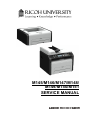
M145/M146/M147/M148/
M149/M150/M151
SERVICE MANUAL
It is the reader's responsibility when discussing the information contained
within this document to maintain a level of confidentiality that is in the best
interest of Ricoh Americas Corporation and its member companies.
NO PART OF THIS DOCUMENT MAY BE REPRODUCED IN ANY
FASHION AND DISTRIBUTED WITHOUT THE PRIOR
PERMISSION OF RICOH AMERICAS CORPORATION.
All product names, domain names or product illustrations, including
desktop images, used in this document are trademarks, registered
trademarks or the property of their respective companies.
They are used throughout this book in an informational or editorial fashion
only and for the benefit of such companies. No such use, or the use of
any trade name, or web site is intended to convey endorsement or other
affiliation with Ricoh products.
2013 RICOH Americas Corporation. All rights reserved.
WARNING
The Service Manual contains information
regarding service techniques, procedures,
processes and spare parts of office equipment
distributed by Ricoh Americas Corporation.
Users of this manual should be either service
trained or certified by successfully completing a
Ricoh Technical Training Program.
Untrained and uncertified users utilizing
information contained in this service manual to
repair or modify Ricoh equipment risk personal
injury, damage to property or loss of warranty
protection.
Ricoh Americas Corporation
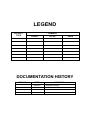
LEGEND
PRODUCT
CODE
COMPANY
LANIER
RICOH
SAVIN
SP 201Nw
SP 201Nw
SP 201Nw
SP 204SN
SP 204SN
SP 204SN
SP 204SFNw
SP 204SFNw
SP 204SFNw
M145
M146
M147
M148
M149
M150
M151
DOCUMENTATION HISTORY
REV. NO.
*
DATE
08/2013
COMMENTS
Original Printing
M145/M146/M147/M148/M149/M150/M151
TABLE OF CONTENTS
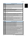
1. PRODUCT INFORMATION .......................................................... 1-1
1.1 SPECIFICATIONS ..................................................................................... 1-1
1.2 NEW PRODUCT INFORMATION .............................................................. 1-2
1.2.1 SERIES MACHINES COMPARED ................................................... 1-2
General Differences ............................................................................. 1-2
Common AIO ....................................................................................... 1-4
1.2.2 FEATURE SUMMARY ...................................................................... 1-5
General Features ................................................................................. 1-5
Duplex Printing ..................................................................................... 1-6
Important Points to Remember ............................................................ 1-6
1.2.3 ABOUT AIO UNITS........................................................................... 1-7
M145, M147, M148, M146 ................................................................... 1-7
M149, M150, M151 .............................................................................. 1-7
M133, M134, M162, M144, M163, M165, M142, M166, M146, M191 .. 1-7
M135, M141, M143, M167, M168, M169.............................................. 1-7
Criteria for Determining the Amount of Remaining Toner and Reporting a
Toner-end Alert .................................................................................... 1-8
AIO Unit Specifications......................................................................... 1-8
1.2.4 GENERAL CONFIGURATION ........................................................ 1-10
M133, M162, M144, M163, M145, M146, M164 Configuration .......... 1-10
M134, M165, M147, M142 Configuration ........................................... 1-11
M135, M141, M166, M148, M143, M167, M149, M168, M150, M151, M169,
M191 Configuration ............................................................................ 1-12
1.2.5 OPERATION PANELS.................................................................... 1-14
M133, M134, M162, M163, M145, M146, M164 Operation Panel ...... 1-14
M134, M142, M165, M147 Operation Panel....................................... 1-15
M135, M141, M143, M166, M148, M167, M149, M168, M150, M151, M169
Operation Panel ................................................................................. 1-16
M191 Operation Panel ....................................................................... 1-17
Alert LEDs .......................................................................................... 1-17
1.2.6 OVERVIEW .................................................................................... 1-18
Paper Path ......................................................................................... 1-18
Drive Layout ....................................................................................... 1-20
Image Writing ..................................................................................... 1-21
SM
i
M145/M146/M147/M148/M149/M150/M151
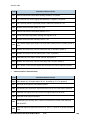
2. INSTALLATION ............................................................................ 2-1
2.1 INSTALLATION REQUIREMENTS............................................................ 2-1
2.1.1 INSTALLATION PROCEDURE ........................................................ 2-1
2.1.2 ENVIRONMENT ............................................................................... 2-1
2.1.3 POWER REQUIREMENT ................................................................. 2-2
2.1.4 MACHINE LEVEL ............................................................................. 2-2
2.1.5 SPACE REQUIREMENTS ................................................................ 2-3
2.1.6 MOVING THE MACHINE.................................................................. 2-4
2.1.7 SMART ORGANIZING MONITOR .................................................... 2-4
2.1.8 IMPORTANT FEATURES................................................................. 2-5
3. PREVENTIVE MAINTENANCE .................................................... 3-1
3.1 CLEANING THE MACHINE ....................................................................... 3-1
3.1.1 BEFORE CLEANING ........................................................................ 3-1
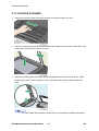
3.1.2 ROUTINE CLEANING ...................................................................... 3-2
4. REPLACEMENT AND ADJUSTMENTS ...................................... 4-1
4.1 BEFORE YOU BEGIN ............................................................................... 4-1
4.1.1 PRECAUTIONS ................................................................................ 4-1
4.1.2 SPECIAL TOOLS ............................................................................. 4-1
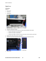
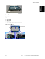
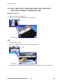
4.1.3 PRINTING THE TEST PAGE AND REPORTS ................................. 4-1
4.2 BASIC PROCEDURES .............................................................................. 4-4
4.2.1 BEFORE YOU BEGIN ...................................................................... 4-4
4.2.2 M133, M162, M144, M163, M145, M146, M164 COVERS ............... 4-4
AIO ....................................................................................................... 4-4
Front Cover .......................................................................................... 4-5
Right Cover .......................................................................................... 4-6
Left Cover............................................................................................. 4-7
Top Cover ............................................................................................ 4-8
Rear Cover ........................................................................................... 4-9
4.2.3 M134, M141, M165, M147, M142 COVERS, PLATEN COVER,
FLATBED UNIT ......................................................................................... 4-9
Platen Cover ........................................................................................ 4-9
AIO ....................................................................................................... 4-9
Front Cover ........................................................................................ 4-10
Right Cover ........................................................................................ 4-11
Left Cover........................................................................................... 4-12
Rear Cover ......................................................................................... 4-13
Left Hinge ........................................................................................... 4-13
Flatbed Scanner Unit ......................................................................... 4-16
M145/M146/M147/M148/M149/M150/M151
ii
SM
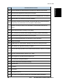
Inner Cover ........................................................................................ 4-17
4.2.4 M135, M143, M167, M149, M168, M150, M166, M148, M191, M151,
M169 COVERS, FLATBED UNIT, ADF ................................................... 4-18
Original Feed Tray ............................................................................. 4-18
AIO ..................................................................................................... 4-18
Front Cover ........................................................................................ 4-19
Right Cover ........................................................................................ 4-20
Left Cover........................................................................................... 4-21
Left Hinge ........................................................................................... 4-23
Rear Cover ......................................................................................... 4-25
ADF/Flatbed Unit ................................................................................ 4-25
Inner Cover ........................................................................................ 4-26
4.2.5 REMOVING THE FUSING UNIT .................................................... 4-27
4.2.6 UTILITIES AND MAINTENANCE ................................................... 4-31
4.3 OPERATION PANELS ............................................................................. 4-33
4.3.1 M133, M162, M144, M163, M145, M146, M164 OPERATION PANEL
4-33
4.3.2 M134, M165, M147, M142 OPERATION PANEL / PANEL COVER 4-33
4.3.3 M135, M141, M143, M167, M149, M168, M150, M166, M148, M151,
M169, M191 OPERATION PANEL .......................................................... 4-35
4.4 LASER UNIT ............................................................................................ 4-37
4.4.1 REMOVING THE LASER UNIT ...................................................... 4-37
4.4.2 AFTER REPLACING THE LASER UNIT ........................................ 4-39
4.5 PAPER PASS .......................................................................................... 4-41
4.5.1 PAPER FEED ROLLER .................................................................. 4-42
4.5.2 FRICTION PAD .............................................................................. 4-44
4.5.3 PAPER TRANSPORT ROLLER ..................................................... 4-45
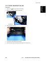
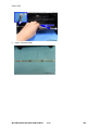
4.5.4 IMAGE TRANSFER ROLLER ......................................................... 4-47
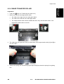
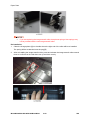
4.5.5 PAPER EXIT ROLLER ................................................................... 4-49
4.6 SENSORS ............................................................................................... 4-50
4.6.1 REGISTRATION SENSOR ............................................................. 4-50
4.6.2 PAPER END SENSOR ................................................................... 4-51
4.6.3 BYPASS SET SENSOR ................................................................. 4-51
4.6.4 PAPER EXIT SENSOR................................................................... 4-52
4.7 MAIN MOTOR.......................................................................................... 4-53
4.7.1 REMOVING THE MAIN MOTOR .................................................... 4-53
4.7.2 REINSTALLING THE MAIN MOTOR.............................................. 4-55
4.8 CLUTCH .................................................................................................. 4-55
4.8.1 PAPER FEED CLUTCH.................................................................. 4-55
SM
iii
M145/M146/M147/M148/M149/M150/M151
4.9 SWITCHES .............................................................................................. 4-56
4.9.1 FRONT DOOR SWITCH................................................................. 4-56
4.9.2 INTERLOCK SWITCH .................................................................... 4-58
4.10 FUSING UNIT .................................................................................... 4-59
4.10.1 SEPARATING THE FUSING UNIT ........................................... 4-59
4.10.2 FUSING EXIT ROLLER ............................................................ 4-61
4.10.3 PRESSURE ROLLER ............................................................... 4-61
4.10.4 HOT ROLLER, FUSING LAMP ................................................. 4-62
4.10.5 THERMOSTAT ......................................................................... 4-63
4.10.6 THERMISTOR .......................................................................... 4-64
4.10.7 GROUND PLATE ...................................................................... 4-64
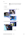
4.11 PCB .................................................................................................... 4-65
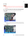
4.11.1 M133, M162, M144, M163, M145, M146, M164 MAIN BOARD 4-65
4.11.2 M134, M141, M165, M147, M142 MAIN BOARD ...................... 4-67
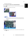
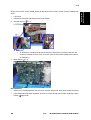
4.11.3 M135, M143, M167, M149, M168, M150, M166, M148, M151, M169,
M191 MAIN BOARD ................................................................................ 4-68
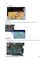
4.11.4 AFTER REPLACING THE MAIN BOARD ................................. 4-71
4.11.5 M135, M141, M143, M167, M149, M168, M150, M151, M169 FAX
BOARD 4-72
4.11.6 M135, M141, M143, M167, M149, M168, M150, M151, M169 FAX
SPEAKER ................................................................................................ 4-74
4.11.7 PSU ........................................................................................... 4-75
4.11.8 H.V.P.P. .................................................................................... 4-77
4.11.9 WI-FI MODULE ......................................................................... 4-79
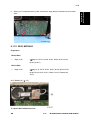
4.12 SCANNER UNIT ................................................................................ 4-82
4.13 ADF (M135, M143, M167, M149, M168, M150, M166, M148, M151, M169,
M191) 4-82
4.14 REFILLING THE AIO ......................................................................... 4-84
4.14.1 BEFORE YOU BEGIN............................................................... 4-84
AIO, Toner Packs ............................................................................... 4-84
Toner End Alert: M133, M134, M142, M162, M163, M165, M166, M164,
M191 .................................................................................................. 4-84
Toner End Alert: M135, M141, M143, M167, M168, M169................. 4-84
More About the Toner End Option ..................................................... 4-84
4.14.2 WHAT YOU NEED .................................................................... 4-86
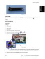
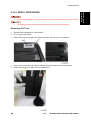
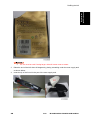
4.14.3 REFILL PROCEDURE .............................................................. 4-87
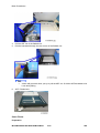
Removing Old Toner .......................................................................... 4-87
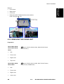
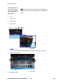
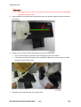
Filling the AIO with New Toner ........................................................... 4-88
5. SYSTEM MAINTENANCE REFERENCE..................................... 5-1
M145/M146/M147/M148/M149/M150/M151
iv
SM
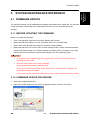
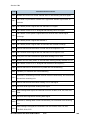
5.1 FIRMWARE UPDATE ................................................................................ 5-1
5.1.1 BEFORE UPDATING THE FIRMWARE ........................................... 5-1
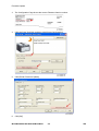
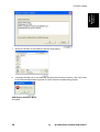
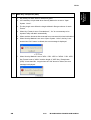
5.1.2 FIRMWARE UPDATE PROCEDURE ............................................... 5-1
5.2 UTILITIES .................................................................................................. 5-7
5.2.1 OVERVIEW OF UTILITIES ............................................................... 5-7
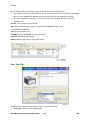
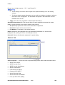
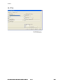
5.2.2 SMART ORGANIZING MONITOR .................................................... 5-7
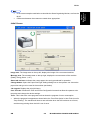
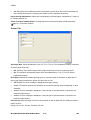
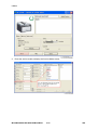
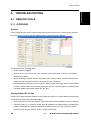
Initial Screen ........................................................................................ 5-9
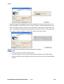
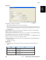
Status Tab Change Button ................................................................. 5-11
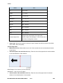
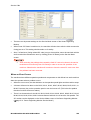
Job Log Tab ....................................................................................... 5-12
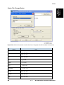
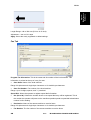
User Tool Tab .................................................................................... 5-14
IP Address Setting dialog ................................................................... 5-15
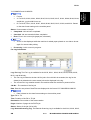
System Tab ........................................................................................ 5-16
Printer Tab ......................................................................................... 5-18
Copy Tab............................................................................................ 5-19
Fax Tab .............................................................................................. 5-21
Scanner Tab....................................................................................... 5-22
Wi-FI Tab ........................................................................................... 5-24
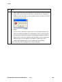
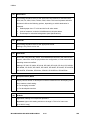
5.2.3 SMART ORGANIZING MONITOR SERVICE MODE ..................... 5-31
What Is Service Mode? ...................................................................... 5-31
Service Mode Screen ......................................................................... 5-31
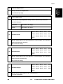
5.2.4 M166, M148, M141, M167, M149, M135, M168, M143, M151, M169,
M191 USER TOOL SPECIFICATION ...................................................... 5-40
System Settings ................................................................................. 5-40
Printer Features Settings.................................................................... 5-46
Copier Features Settings.................................................................... 5-47
Fax Features Settings (M141, M167, M149, M135, M168, M150, M143,
M151, M169) ...................................................................................... 5-50
Scanner Features Settings ................................................................. 5-56
Network Settings (M168, M150, M143, M151, M164) ........................ 5-59
Address Book Settings (M135, M141, M143, M167, M149, M168, M150,
M151, M169) ...................................................................................... 5-60
Printing Lists/Reports (M166, M148, M141, M167, M149, M135, M168,
M150, M143, M151, M169) ................................................................ 5-60
5.2.5 FAX MAINTENANCE (M135, M141, M143, M167, M149, M168, M150,
M151, M169) ............................................................................................ 5-61
5.2.6 FAX TEST (M135, M141, M143, M167, M149, M168, M150, M151,
M169) ....................................................................................................... 5-70
6. TROUBLESHOOTING ................................................................. 6-1
6.1 SERVICE CALLS ....................................................................................... 6-1
SM
v
M145/M146/M147/M148/M149/M150/M151
6.1.1 OVERVIEW ...................................................................................... 6-1
General ................................................................................................ 6-1
Fusing Related SC Codes .................................................................... 6-1
When an Error Occurs.......................................................................... 6-2
6.1.2 EXECUTING FUSER SC RESET ..................................................... 6-4
6.1.3 SC TABLES ...................................................................................... 6-4
SC Table Key ....................................................................................... 6-4
SC100: Scanning ................................................................................. 6-5
SC200: Scanning ................................................................................. 6-6
SC400: Around the Drum ..................................................................... 6-8
SC500: Paper Feed, Transport ............................................................ 6-8
SC600: Communication ..................................................................... 6-13
SC800: Other ..................................................................................... 6-14
6.1.4 ERROR CODES ............................................................................. 6-14
Classification ...................................................................................... 6-14
FATAL ................................................................................................ 6-15
Error ................................................................................................... 6-16
Supplement ........................................................................................ 6-22
6.2 IMAGE PROBLEMS ................................................................................ 6-28
6.2.1 OVERVIEW .................................................................................... 6-28
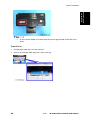
6.2.2 PRINTING THE TEST PAGE ......................................................... 6-29
Print the Test Page without Smart Organizing Monitor ...................... 6-29
6.2.3 DARK LINES IN HALFTONE AREAS ............................................. 6-30
6.3 COMMON PROBLEMS ........................................................................... 6-32
6.3.1 ALL MODELS ................................................................................. 6-32
6.3.2 M133, M134, M162, M144, M163, M165, M142, M166, M164, M1916-33
6.3.3 M135, M141, M143, M167, M168, M169 ........................................ 6-34
7. ENERGY SAVING ........................................................................ 7-1
7.1 ENERGY SAVE ......................................................................................... 7-1
7.1.1 ENERGY SAVE MODES .................................................................. 7-1
Energy Save Operation ........................................................................ 7-1
Timer Settings and Return to Standby Mode ....................................... 7-2
Recommendations ............................................................................... 7-2
7.2 PAPER SAVE ............................................................................................ 7-3
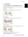
7.2.1 EFFECTIVENESS OF DUPLEX/COMBINE FUNCTIONS................ 7-3
1. Duplex .............................................................................................. 7-3
2. Combine Mode ................................................................................. 7-3
3. Duplex + Combine............................................................................ 7-3
Total Counter ....................................................................................... 7-4
M145/M146/M147/M148/M149/M150/M151
vi
SM
READ THIS FIRST
Safety, Symbols, Trademarks, and Important Safety Notices
Conventions
Commonly Used Icons for Replacements and Adjustments
Symbol
What it means
Binding screw (shoulder hexagonal head)
Binding screw (round flathead)
Black screw (heavy, fusing unit, TCRU)
Bushing
C-ring
Connector
E-ring
FFC (Flat Film Connector)
FFC (Flat Film Connector)
Gear
Harness clamp
Harness clamp (metal: fusing unit)
Hook (or tab release)
Knob screw (black)
Knob screw (silver)
Pivot screw
Screw (common screw)
Shoulder screw
Spring
Symbol
What it means
Standoff
Stud screw
Tapping screw (wide threads for plastic)
Timing belt
Paper Feed: SEF/LEF
The notations "SEF" and "LEF" describe the direction of paper feed. The arrows indicate the
direction of paper feed.
[A] Short Edge Feed (SEF)
[B] Long Edge Feed (LEF)
In this manual "Main Scan" means "Horizontal" and "Sub Scan" means "Vertical", both relative to
the direction of paper feed.
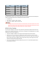
Smart Organizing Monitor
In this service manual "Smart Organizing Monitor" is often abbreviated as "SOM".
The detailed procedure for entering the service mode of the Smart Organizing Monitor is
provided in the training materials for these machines. The procedure for entering the
service mode is not described in the service manuals.
Service technicians must know how to enter the service mode before servicing these
machines. Please refer to the training materials.
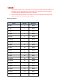
Machine Names
Name
Abbrev.
Model No.
SP 200
P
M133
SP 200
P
M162
SP 200N
P
M144
SP 200N
P
M163
SP 201N
P
M145
SP 200Nw
P
M164
SP 201Nw
P
M146
SP 200S
TiO
M134
SP 200S
TiO
M165
SP 201S
TiO
M142
SP 202S
TiO
M191
SP 203S
TiO
M147
SP 202SN
TiO
M166
SP 204SN
TiO
M148
SP 201SF
FiO
M135
SP 200SF
FiO
M141
SP 202SF
FiO
M143
SP 203SF
FiO
M167
SP 204SF
FiO
M149
Name
Abbrev.
Model No.
SP 203SFN
FiO
M168
SP 204SFN
FiO
M150
SP 203SFNw
FiO
M169
SP 204SFNw
FiO
M151
The abbreviated notations in the second column above (not used in these service manuals) are
used in the operating instructions to distinguish the machine models:
P: Printer only
TiO: Three-in-1 (printer, copier, scanner)
FiO: Four-in-1 (printer, copier, scanner, fax)
Throughout this manual the machines are referenced by the model numbers only: M133,
M162, M144, M163, M145, M134, M165, M147, M142, M166, M148, M135, M141, M143,
M167, M149, M168, M150, M146, M164, M151, M169, and M191.
AIO (All In One) Cartridge
The AIO (print cartridge) in the center of the machine is permanently sealed around these main
elements of the printing mechanisms: 1) OPC drum, 2) charge unit, 3) development unit, 4) drum
cleaning unit, and 5) toner supply unit.
This print cartridge is called the "AIO" (All-In-One) throughout this service manual.
When toner runs out, the AIO can be refilled by the service technician or the AIO can be
replaced by the operator. Refilling requires removal of two caps: the square cap to dump the
toner and the round cap for refilling. These two parts are the only service parts for the AIO.
There are no other service parts for the AIO.
The AIO can be easily removed and replaced by the user. For more details, please refer to
the operating instructions.
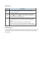
Key Presses
Symbol
[Key]
What It Means
The names of machine operation panel keys and PC keyboard keys are
enclosed in square brackets.
This means to press one of the arrow keys to move the menu selector
Select
up/down (
) or left/right (
) to the menu selection you want and then
press [OK] on the machine operation panel.
A right angle bracket means to select a menu item (enclosed in quotation
marks) by pressing the right or left arrow key and then pressing [OK]. For
>
example,
[User Tools] > Select "System Settings" > "Tray Paper Settings"
means, Press the [User Tools], press the right arrow to highlight "System
Settings" and press [OK], and then press [OK] to select "Tray Paper Settings".
RoHS Compliance
These machines are fully compliant with Chinese RoHS and contain no restricted materials such
as lead, mercury, cadmium, hexavalent chrome, polybrominated biphenyl, or polybrominated
diphenyl ether.
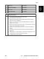
Warnings, Cautions, Notes
In this manual, the following important symbols and notations are used.
A Warning indicates a potentially hazardous situation. Failure to obey a Warning could
result in death or serious injury.
A Caution indicates a potentially hazardous situation. Failure to obey a Caution could
result in minor or moderate injury or damage to the machine or other property.
Obey these guidelines to avoid problems such as misfeeds, damage to originals, loss of
valuable data and to prevent damage to the machine.
This information provides tips and advice about how to best service the machine.
General Safety Instructions
For your safety, please read this manual carefully before you use this product. Keep this manual
handy for future reference.
Safety Information
Always obey the following safety precautions when using this product.
Safety During Operation
In this manual, the following important symbols and notations are used.
Switches and Symbols
Where symbols are used on or near switches on machines for Europe and other areas, the
meaning of each symbol conforms with IEC60417.
Responsibilities of the Customer Engineer
Customer Engineer
Maintenance shall be done only by trained customer engineers who have completed service
training for the machine and all optional devices designed for use with the machine.
Reference Material for Maintenance
Maintenance shall be done using the special tools and procedures prescribed for
maintenance of the machine described in the reference materials (service manuals, technical
bulletins, operating instructions, and safety guidelines for customer engineers).
Use only consumable supplies and replacement parts designed for use with the machine.
Before Installation, Maintenance
Shipping and Moving the Machine
Work carefully when lifting or moving the machine. If the machine is heavy, two or more
customer engineers may be required to prevent injuries (muscle strains, spinal injuries,
etc.) or damage to the machine if it is dropped or tipped over.
Personnel moving or working around the machine should always wear proper clothing
and footwear. Never wear loose fitting clothing or accessories (neckties, loose sweaters,
bracelets, etc.) or casual footwear (slippers, sandals, etc.) when lifting or moving the
machine.
Always unplug the power cord from the power source before you move the machine.
Before you move the product, arrange the power cord so it will not fall under the machine.
Power
Always disconnect the power plug before doing any maintenance procedure. After
switching off the machine, power is still supplied to the main machine and other devices.
To prevent electrical shock, switch the machine off, wait for a few seconds, then unplug
the machine from the power source.
Before you do any checks or adjustments after turning the machine off, work carefully to
avoid injury. After removing covers or opening the machine to do checks or adjustments,
never touch electrical components or moving parts (gears, timing belts, etc.).
After turning the machine on with any cover removed, keep your hands away from
electrical components and moving parts. Never touch the cover of the fusing unit, gears,
timing belts, etc.
Installation, Disassembly, and Adjustments
After installation, maintenance, or adjustment, always check the operation of the machine
to make sure that it is operating normally. This ensures that all shipping materials,
protective materials, wires and tags, metal brackets, etc., removed for installation, have
been removed and that no tools remain inside the machine. This also ensures that all
release interlock switches have been restored to normal operation.
Never use your fingers to check moving parts causing spurious noise. Never use your
fingers to lubricate moving parts while the machine is operating.
Special Tools
Use only standard tools approved for machine maintenance.
For special adjustments, use only the special tools and lubricants described in the service
manual. Using tools incorrectly, or using tools that could damage parts, could damage the
machine or cause injuries.
During Maintenance
General
Before you begin a maintenance procedure: 1) Switch the machine off, 2) Disconnect the
power plug from the power source, 3) Allow the machine to cool for at least 10 minutes.
Avoid touching the components inside the machine that are labeled as hot surfaces.
Safety Devices
Never remove any safety device unless it requires replacement. Always replace safety
devices immediately.
Never do any procedure that defeats the function of any safety device. Modification or
removal of a safety device (fuse, switch, etc.) could lead to a fire and personal injury.
Always test the operation of the machine to ensure that it is operating normally and safely
after removal and replacement of any safety device.
For replacements use only the correct fuses or circuit breakers rated for use with the
machine. Using replacement devices not designed for use with the machine could lead to
a fire and personal injuries.
Organic Cleaners
During preventive maintenance, never use any organic cleaners (alcohol, etc.) other than
those described in the service manual.
Make sure the room is well ventilated before using any organic cleaner. Use organic
solvents in small amounts to avoid breathing the fumes and becoming nauseous.
Switch the machine off, unplug it, and allow it to cool before doing preventive
maintenance. To avoid fire or explosion, never use an organic cleaner near any part that
generates heat.
Wash your hands thoroughly after cleaning parts with an organic cleaner to prevent
contamination of food, drinks, etc. which could cause illness.
Clean the floor completely after accidental spillage to prevent slippery surfaces that could
cause accidents leading to hand or leg injuries. Use dry rags to soak up spills.
Power Plug and Power Cord
Before servicing the machine (especially when responding to a service call), always
make sure that the power plug has been inserted completely into the power source. A
partially inserted plug could lead to heat generation (due to a power surge caused by
high resistance) and cause a fire or other problems.
Always check the power plug and make sure that it is free of dust and lint. Clean it if
necessary. A dirty plug can generate heat which could cause a fire.
Inspect the length of the power cord for cuts or other damage. Replace the power cord if
necessary. A frayed or otherwise damaged power cord can cause a short circuit which
could lead to a fire or personal injury from electrical shock.
Check the length of the power cord between the machine and power supply. Make sure
the power cord is not coiled or wrapped around any object such as a table leg. Coiling the
power cord can cause excessive heat to build up and could cause a fire.
Make sure that the area around the power source is free of obstacles so the power cord
can be removed quickly in case of an emergency.
Make sure that the power cord is grounded (earthed) at the power source with the ground
wire on the plug.
Connect the power cord directly into the power source. Never use an extension cord.
When you disconnect the power plug from the power source, always pull on the plug, not
the cable.
After Installation, Servicing
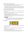
Disposal of Used Items
Never incinerate used toner, toner cartridges, or AIO units.
Toner thrown into a fire can ignite or explode and cause serious injury. At the work site
always carefully wrap used toner and toner cartridges with plastic bags to avoid spillage
before disposal or removal.
Always dispose of used items (developer, toner, toner cartridges, OPC drums, AIO units,
etc.) in accordance with the local laws and regulations regarding the disposal of such
items.
To protect the environment, never dispose of this product or any kind of waste from
consumables at a household waste collection point. Dispose of these items at one of our
dealers or at an authorized collection site.
Return used drums to the service center for handling in accordance with company policy
regarding the recycling or disposal of such items.
Points to Confirm with Operators
At the end of installation or a service call, instruct the user about use of the machine. Emphasize
the following points.
Show operators how to remove jammed paper and troubleshoot other minor problems by
following the procedures described in the operating instructions.
Point out the parts inside the machine that they should never touch or attempt to remove.
Confirm that operators know how to store and dispose of consumables.
Make sure that all operators have access to an operating instruction manual for the machine.
Confirm that operators have read and understand all the safety instructions described in the
operating instructions.
Demonstrate how to turn off the power and disconnect the power plug (by pulling the plug, not
the cord) if any of the following events occur: 1) something has spilled into the product, 2)
service or repair of the product is necessary, 3) the product cover has been damaged.
Caution operators about removing paper fasteners around the machine. They should never
allow paper clips, staples, or any other small metallic objects to fall into the machine.
Special Safety Instructions for Toner
Accidental Physical Exposure
Work carefully when removing paper jams or replacing toner bottles or cartridges to avoid
spilling toner on clothing or the hands.
If toner is inhaled, immediately gargle with large amounts of cold water and move to a
well ventilated location. If there are signs of irritation or other problems, seek medical
attention.
If toner gets on the skin, wash immediately with soap and cold running water.
If toner gets into the eyes, flush the eyes with cold running water or eye wash. If there are
signs of irritation or other problems, seek medical attention.
If toner is swallowed, drink a large amount of cold water to dilute the ingested toner. If
there are signs of any problem, seek medical attention.
If toner spills on clothing, wash the affected area immediately with soap and cold water.
Never use hot water! Hot water can cause toner to set and permanently stain fabric.
Handling and Storing Toner
Toner, used toner, and developer are extremely flammable.
Never store toner, developer, toner cartridges, or toner bottles (including empty toner
bottles or cartridges), or AIO units in a location where they will be exposed to high
temperature or an open flame.
Do not use a vacuum cleaner to remove spilled toner (including used toner). Vacuumed
toner may cause a fire or explosion due to sparks or electrical contact inside the cleaner.
However, it is possible to use a cleaner designed to be dust explosion-proof. If toner is
spilled over the floor, sweep up spilled toner slowly and clean up any remaining toner with
a wet cloth.
Always store toner and developer supplies such as toner and developer packages,
cartridges, bottles (including used toner and empty bottles and cartridges) and AIO units
out of the reach of children.
Always store fresh toner supplies or empty bottles or cartridges in a cool, dry location that
is not exposed to direct sunlight.
Toner Disposal
Never attempt to incinerate toner, used toner, or empty toner containers (bottles or
cartridges). Burning toner can explode and scatter, causing serious burns.
Always wrap used toner and empty toner bottles and cartridges in plastic bags to avoid
spillage. Follow the local laws and regulations regarding the disposal of such items.
Dispose of used toner and toner cartridges at one of our dealers or at an authorized
collection site. Always dispose of used toner cartridges and toner bottles in accordance
with the local laws and regulations regarding the disposal of such items.
Safety Instructions for the Machine
Prevention of Physical Injury
1.
Before disassembling or assembling parts of the machine and peripherals, make sure that the
machine and peripheral power cords are unplugged.
2.
The plug should be near the machine and easily accessible.
3.
Note that some components of the machine and the paper tray unit are supplied with
electrical voltage even if the main power switch is turned off.
4.
If any adjustment or operation check has to be made with exterior covers off or open while the
main switch is turned on, keep hands away from electrified or mechanically driven
components.
5.
If the [Start] key is pressed before the machine completes the warm-up period (the [Start] key
starts blinking red and green), keep hands away from the mechanical and the electrical
components, because the machine starts making copies as soon as the warm-up period is
completed.
6.
The inside and the metal parts of the fusing unit become extremely hot while the machine is
operating. Be careful to avoid touching those components with your bare hands.
7.
To prevent a fire or explosion, keep the machine away from flammable liquids, gases, and
aerosols.
Health Safety Conditions
1.
If the machine has ozone filters, never operate the machine without the ozone filters installed.
Always replace the ozone filters with the specified types at the proper intervals.
2.
To avoid possible accumulation of ozone in the work area, locate the machine in a large well
ventilated room that has an air turnover rate of more than 30m3/hr/person.
3.
Toner and developer are non-toxic, but if you get either of them in your eyes by accident, it
may cause temporary eye discomfort. Try to remove with eye drops or flush with water as first
aid. If unsuccessful, get medical attention.
Observance of Electrical Safety Standards
1.
The machine and its peripherals must be installed and maintained by a customer service
representative who has completed the training course on those models.
2.
The NVRAM on the system control board has a lithium battery which can explode if replaced
incorrectly. Replace the NVRAM only with an identical one. The manufacturer recommends
replacing the entire NVRAM. Do not recharge or burn this battery. Used NVRAM must be
handled in accordance with local regulations.
Safety and Ecological Notes for Disposal
1.
Never incinerate toner bottles or used toner. Toner dust may ignite suddenly when exposed to
an open flame.
2.
Dispose of used toner, developer, and organic photoconductors in accordance with local
regulations. (These are non-toxic supplies.)
3.
Dispose of replaced parts in accordance with local regulations.
4.
When keeping used lithium batteries in order to dispose of them later, do not put more than
100 batteries per sealed box. Storing larger numbers or not sealing them apart may lead to
chemical reactions and heat build-up.
The danger of explosion exists if a battery of this type is incorrectly replaced.
Replace only with the same or an equivalent type recommended by the manufacturer.
Discard used batteries in accordance with the manufacturer's instructions.
Laser Safety
1.
The Center for Devices and Radiological Health (CDRH) prohibits the repair of laser-based
optical units in the field.
2.
The optical housing unit can only be repaired in a factory or at a location with the requisite
equipment.
3.
The laser subsystem is replaceable in the field by a qualified Customer Engineer.
4.
The laser chassis is not repairable in the field.
5.
Customer engineers are therefore directed to return all chassis and laser subsystems to the
factory or service depot when replacement of the optical subsystem is required.
Use of controls, or adjustment, or performance of procedures other than those specified
in this manual may result in hazardous radiation exposure.
Turn off the main switch before attempting any of the procedures in the Laser Unit section.
Laser beams can seriously damage your eyes.
Trademarks
Microsoft®, and Windows® are registered trademarks of Microsoft Corporation in the United
States and /or other countries.
PostScript® is a registered trademark of Adobe Systems, Incorporated.
PCL® is a registered trademark of Hewlett-Packard Company.
Ethernet® is a registered trademark of Xerox Corporation.
PowerPC® is a registered trademark of International Business Machines Corporation.
Other product names used herein are for identification purposes only and may be trademarks
of their respective companies. We disclaim any and all rights involved with those marks.
PRODUCT INFORMATION
R E V I S I O N H I S T O RY
Pa ge
Da te
Ad de d /U pd ate d /New
None
Specifications
Product
Information
1. PRODUCT INFORMATION
1.1 SPECIFICATIONS
See "Appendices" for the following information:
Before You Read These Specifications
General Specifications
Printer Specifications
Copier Specifications (M134, M165, M147, M142, M166, M148, M135, M141, M143, M167,
M149, M168, M150, M151, M169, M191)
Scanner Specifications (M134, M165, M147, M142, M166, M148, M135, M141, M143, M167,
M149, M168, M150, M151, M169, M191)
Fax Specifications (M135, M141, M143, M167, M149, M168, M150, M151, M169)
Reports
Software Specifications
SM
1-1
M145/M146/M147/M148/M149/M150/M151
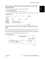
New Product Information
1.2 NEW PRODUCT INFORMATION
1.2.1 SERIES MACHINES COMPARED
General Differences
Throughout this manual the machines are referenced by the model numbers only: M133,
M162, M144, M163, M145, M134, M165, M147, M142, M166, M148, M135, M141, M143,
M167, M149, M168, M150, M140, M164, M151, M169, and M191.
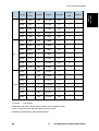
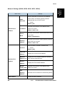
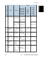
The 18-type machines can be identified by their external appearances.
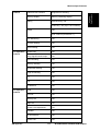
Model
ADF/
Platen
n/usb/wifi
Display
AIO:R/NR
Scan to
USB
Handset
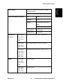
M135
ADF
usb
2-LINE
R
-
Y
M141
Platen
usb
2-LINE
R
-
Y
M143
ADF
n
2-LINE
R
-
Y
M167
ADF
usb
2-LINE
R
-
4in1
M145/M146/M147/M148/M149/M150/M151
1-2
SM
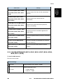
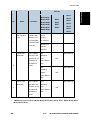
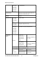
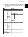
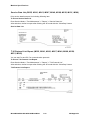
Model
3in1
Printer
ADF/
Platen
n/usb/wifi
Display
AIO:R/NR
Scan to
USB
Handset
M149
ADF
usb
2-LINE
NR
-
-
M168
ADF
n
2-LINE
R
Y
-
M150
ADF
n
2-LINE
NR
Y
-
M169
ADF
wifi
2-LINE
R
Y
-
M151
ADF
wifi
2-LINE
NR
Y
-
M134
Platen
usb
2-digit
R
-
-
M165
Platen
usb
2-digit
R
-
-
M147
Platen
usb
2-digit
NR
-
-
M142
Platen
n
2-digit
R
-
-
M166
ADF
n
2-LINE
R
Y
-
M148
ADF
n
2-LINE
NR
Y
-
M191
ADF
usb
2-LINE
R
-
-
M133
-
usb
2 LEDs
R
-
-
M162
-
usb
2 LEDs
R
-
-
M144
-
n
2 LEDs
R
-
-
M163
-
n
2 LEDs
R
-
-
M145
-
n
2 LEDs
NR
-
-
M164
-
wifi
2 LEDs
R
-
-
M146
-
wifi
2 LEDs
NR
-
-
Y: Support
- : Not support
ADF/Platen: ADF=ADF model, Platen= Platen cover model(Non-ADF)
n/usb: n=network model, usb=usb model, wifi=wi-fi model
AIO:R/NR: R=Refill model, NR=Not Refill model
SM
1-3
M145/M146/M147/M148/M149/M150/M151
Product
Information
New Product Information
New Product Information
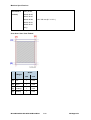
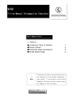
Common AIO
No.
Part
No.
Part
1
Waste Toner Tank
7
Toner Supply Roller
2
Development Roller
8
Image Transfer Roller
3
Toner Hopper
9
Drum
4
ID Chip
10
Charge Roller
5
Agitator
11
Cleaning Blade
6
Agitator Feeler
Throughout the service manual this unit is called the "AIO" (All-In-One).
The AIO is common to all machines of this series.
There are no serviceable parts inside the AIO. (Disassembly of an AIO is never required.)
When the AIO runs out of toner, the toner waste tank can be emptied and the toner supply
tank can be refilled with fresh developer/toner.
An AIO can be refilled up to three times (this is the approximate service life of the drum). The
refillings greatly extend the service life of the AIO.
The AIO can be easily removed and replaced by the user.
The AIO has an ID chip which helps the machine to detect when an AIO is set and when a
new AIO has been installed.
M145/M146/M147/M148/M149/M150/M151
1-4
SM
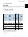
1.2.2 FEATURE SUMMARY
General Features
Unlike other machines in their class, these machines are not inkjet or GelJet printers—they are
laser printers. The three machines of this series have these common features:
Thin printers have a small footprint and require little space.
They are extremely light and easy to carry:
4in1 models: 11.1 kg (24.5 lb.) or less
3in1 models: 9.9 kg (21.8 lb.) or less
Printer models: 7.2 kg (15.9 lb.) or less
Their AIO units are identical and allow up to three refills with non-toxic developer/toner.
Here is a quick feature comparison.
M135
M133
M162
M144
Standard
M163
Features
M145
M146
M143
M134
M167
M165
M149
M147
M168
M142
M150
M166
M141
M148
M191
M151
M164
M169
ADF Unit
No
No
Yes
No
Yes
Fax Unit
No
No
Yes
Yes
No
2 keys & 2 LEDs
2-digit
2-line
2-line
2-line
Yes
Yes
Yes
Yes
Yes
Yes
Yes
Yes
Yes
Yes
No
Yes
No
Yes
No
Operation Panel
Output Tray
(50 sheets)
Paper Tray
(150 sheets)
Platen
The following features are not supported by these machines:
Bulk paper feed unit (only one small tray is available)
USB2 Print
NRS support (no UZ, Basil, or Cumin options available)
Memory expansion
SM
1-5
M145/M146/M147/M148/M149/M150/M151
Product
Information
New Product Information
New Product Information
HDD expansion
G3 expansion (no G3 option available)
PictBridge
Duplex Printing
These machines have no mechanism for automatic duplexing.
However, the operator can run a print job and print on the first side of the pages, remove the
printed sheets from the output tray, turn the stack over so the blank side is facing up, load the
stack in the paper feed tray, and then run another job to print on the second sides of the
pages.
Both portrait and landscape printing are possible. Duplex printing must be set up with the print
application. For more details, refer to the operating instructions.
Important Points to Remember
These are very important points to keep in mind while using the service manual:
Functionality. M135, M166, M148, M143, M167, M149, M168, M150, M151, M169, and
M191 have both the ADF and flatbed unit.
Smart Organizing Monitor. This utility (installed with the printer driver at installation) is used
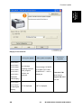
to configure the system and handle errors of all machines of this series.
Message and error displays. M135, M141, M166, M148, M143, M167, M149, M168, M150,
M151, M169, and M191 have a 2-line display that can show errors (SC codes) and messages.
The M134, M165, M147, M142, M146, and M164 display are limited to two digits, and the
M133, M162, M144, M163, and M145 have no display. The Service Mode of Smart
Organizing Monitor can be used to view error messages for all machines.
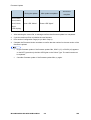
User Tool. The M135, M141, M143, M167, M149, M168, M150, M151, M169, and M191
have a [User Tool] button which opens the User Tool menu settings used to configure the
machine. The Service Mode of the Smart Organizing Monitor is used to configure all
machines.
Scanning. The M135, M141, M165, M147, M142, M166, M148, M143, M167, M149, M168,
M150, M151, and M169 both support applications that use the TWAIN and WIA drivers for
scanning. The originals can be scanned and saved directly onto a computer disk.
M145/M146/M147/M148/M149/M150/M151
1-6
SM
New Product Information
Product
Information
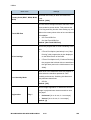
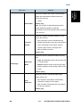
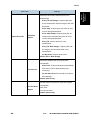
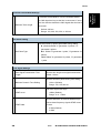
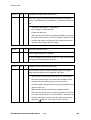
1.2.3 ABOUT AIO UNITS
AIO units vary depending on the model being used.
M145, M147, M148, M146
Printers, 3-in-1 models
With the M145, M147, and M146, which can detect the amount of remaining toner but have
no display on the control panel, the amount of remaining toner appears in Smart Organizing
Monitor. With the M148, which has a two-line display, the amount of remaining toner appears
on the control panel as well as in Smart Organizing Monitor.
If the toner is at near end or toner end, the machine issues the alert. Replace the AIO unit to
refill the toner, since the toner alone cannot be refilled.
"Toner End Option" is not included in User Tools.
M149, M150, M151
4-in-1 models
Capable of detecting the amount of remaining toner. The amount of remaining toner appears
on the control panel and also in Smart Organizing Monitor.
If the toner is at near end or toner end, it is reported. Replace the AIO unit to refill the toner,
since the toner alone cannot be refilled.
"Toner End Option" is included in User Tools. If set to "Continue Printing", the amount of
remaining toner is not determined. In this case, even if the toner is at near end or toner end,
the machine does not issue the alert.
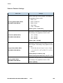
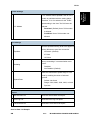
M133, M134, M162, M144, M163, M165, M142, M166, M146, M191
Printers, 3-in-1 models capable of being refilled
Equipped with AIO units with caps for refilling the toner
Cannot determine the amount of remaining toner
Cannot issue an alert when the toner is at near end or toner end
Refill the toner either by replacing the AIO unit or by refilling the AIO unit with toner.
"Toner End Option" is not included in User Tools.
M135, M141, M143, M167, M168, M169
4-in-1 models capable of being refilled
Equipped with AIO units with caps for refilling the toner
When using a starter or other genuine AIO unit, the amount of remaining toner can be
determined, and if the toner is at near end or toner end, the machine issues the alert.
However, if a refilled AIO unit is installed, it is not possible to determine the amount of
remaining toner, toner-near-end or toner-end.
SM
1-7
M145/M146/M147/M148/M149/M150/M151
New Product Information
"Toner End Option" is included in User Tools. If set to "Continue Printing", the amount of
remaining toner is not determined even if a starter or other genuine AIO unit is being used. In
this case, even if the toner is at near end or toner end, the machine does not report an alert.
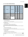
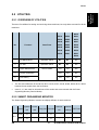
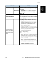
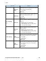
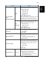
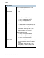
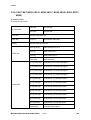
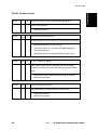
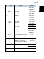
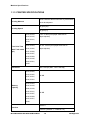
Criteria for Determining the Amount of Remaining Toner and Reporting a
Toner-end Alert
Model
M145, M147,
M148, M146
M149, M150,
M151
Criteria for determining the amount of remaining toner and reporting
a toner-end/toner-near-end alert
Capable of determination and notification.
Operates as if "Toner End Option" is set to "Stop Printing" at all
times.
Capable of determination and notification if "Toner End Option" is
set to "Stop Printing".
As the default, "Toner End Option" is set to "Stop Printing".
M133, M134,
M162, M144,
Not capable of determination and notification.
M163, M165,
Operates as if "Toner End Option" is set to "Continue Printing" at all
M142, M166,
times.
M164, M191
M135, M141,
M143, M167,
M168, M169
Capable of determination and notification if a starter or other
genuine AIO unit is installed and "Toner End Option" is set to "Stop
Printing".
As the default, "Toner End Option" is set to "Stop Printing".
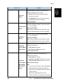
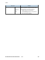
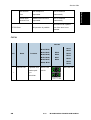
AIO Unit Specifications
Starter AIO
M133, M162, M144, M163, M134, M165, M142, M166, M135, M141, M143, M167, M168,
M164, M169, M191: 1.0K
M145, M147, M148, M149, M150, M146, M151: 0.70K
Replacement AIO Unit
China: only 2.6K
Regions Other than China: 1.5K and 2.6K
M145/M146/M147/M148/M149/M150/M151
1-8
SM
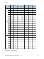
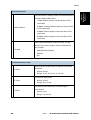
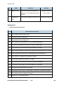
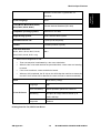
M133, M134,
M135, M141,
M149
M162, M144,
M143, M167,
M150
M163, M165,
M168, M169
M151
M142, M166,
Function
M164, M191
Refilled
AIO
Unit
ID chip
Genuine Genuine
Refilled
M145
M147
M148
M146
Genuine Genuine
AIO Unit AIO Unit AIO Unit AIO Unit AIO Unit
Y
Y
Y
Y
Y
Y
Y
Y
Y
Y
Y
Y
-
Y
Y
-
-
Y
-
Y
Y
-
-
Y
-
Y
Y
-
-
Y
Reporting toner near end
-
Y
Y
-
-
Y
Reporting toner end
-
Y
Y
-
-
Y
-
Y
Y
-
-
Y
-
Y
Y
-
-
Y
Y
Y
Y
-
-
-
(Installed)
Detecting installation
(Checking by the ID chip
whether the AIO unit is installed)
Detecting new products
(Checking whether the installed
AIO unit is unused)
Photoconductor life
(Determining the
photoconductor life and notifying
the user when it is nearing its
end)
Photoconductor life
(Determining the
photoconductor life and notifying
the user when it has ended)
Waster toner bottle notification
(Notifying the user when the
waster toner bottle is full)
50 pages print after reporting
toner end
Toner End Option (User Tools)
SM
1-9
M145/M146/M147/M148/M149/M150/M151
Product
Information
New Product Information
New Product Information
Y: Supported
-: Not Supported
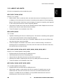
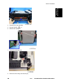
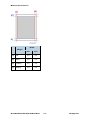
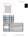
1.2.4 GENERAL CONFIGURATION
M133, M162, M144, M163, M145, M146, M164 Configuration
1.
[Job Reset] key
Press this key to cancel an ongoing print job.
2.
[Start] key
Press this key to resume printing if printing stops due to paper running out or a paper setting
error.
3.
Power Indicator
This indicator lights up green when the machine is turned on. If flashes when a print job is
received and while printing is in progress.
4.
Alert Indicator
This indicator lights up red when the machine runs out of paper or consumables, when the
paper settings do not match the setting specified by the driver, or other errors occur.
5.
Output Tray
Printed paper is output here.
6.
Front Cover
Lift up this cover to replace consumables or clear a paper jam.
7.
Bypass Tray
This tray can hold up to one sheet of plain paper.
8.
Tray 1
This tray can hold up to 150 sheets of plain paper.
9.
Power Switch
Use this switch to turn the power on or off.
M145/M146/M147/M148/M149/M150/M151
1-10
SM
New Product Information
Connect the power cord to the machine here. Insert the other end of the cable into a nearby
wall outlet.
11. Rear Door
Open this cover to deliver sheets face up or remove jammed paper.
12. USB Port
Use this port to connect the machine to a computer using a USB cable.
13. Ethernet Port (M144, M163, and M145, M146, M164 only)
Use this port to connect the machine to network using an Ethernet cable.
14. Tray Cover
Attach this cover when you extend the tray.
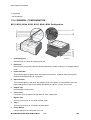
M134, M165, M147, M142 Configuration
1.
Exposure Glass
Place originals here sheet by sheet.
2.
Control Panel
Contains a screen and keys for machine control.
3.
Exposure Glass Cover
Open this cover to place originals on the exposure glass.
4.
Output Tray
Printed paper is output here.
5.
Front Cover
Lift up this cover to replace consumables or clear a paper jam.
6.
Bypass Tray
This tray can hold up to one sheet of plain paper.
SM
1-11
M145/M146/M147/M148/M149/M150/M151
Product
Information
10. Power Connector
New Product Information
7.
Tray 1
This tray can hold up to 150 sheets of plain paper.
8.
Power Switch
Use this switch to turn the power on or off.
9.
Power Connector
Connect the power cord to the machine here. Insert the other end of the cable into a nearby
wall outlet.
10. Rear Door
Open this cover to deliver sheets face up or remove jammed paper.
11. USB Port
Use this port to connect the machine to a computer using a USB cable.
12. Ethernet Port (M142 only)
Use this port to connect the machine to network using an Ethernet cable.
13. Tray Cover
Attach this cover when you extend the tray.
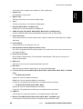
M135, M141, M166, M148, M143, M167, M149, M168, M150, M151, M169, M191
Configuration
1.
In the M141, Auto Document Feeder (ADF) has not been installed.
Exposure Glass
Place originals here sheet by sheet.
2.
Control Panel
Contains a screen and keys for machine control.
3.
Front Cover
M145/M146/M147/M148/M149/M150/M151
1-12
SM
New Product Information
Lift up this cover to replace consumables or clear a paper jam.
Output Tray
Product
Information
4.
Printed paper is output here.
5.
Bypass Tray
This tray can hold up to one sheet of plain paper.
6.
Tray 1
This tray can hold up to 150 sheets of plain paper.
7.
Handset (M135, M141, and M143 only)
Enables you to use the machine as a telephone.
8.
USB Flash Disk Port (M150, M168, M148, M166, M151, and M169 only)
Insert a USB flash disk to store scanned files using the Scan to USB function.
9.
Power Connector
Connect the power cord to the machine here. Insert the other end of the cable into a nearby
wall outlet.
10. Power Switch
Use this switch to turn the power on or off.
11. Auto Document Feeder (Exposure Glass Cover)
The ADF is integrated with the exposure glass cover. Open this cover to place documents on
the exposure glass.
12. Input Tray for the ADF
Place stacks of originals here. They will feed in automatically. This tray can hold up to 15
sheets of plain paper.
13. ADF Cover
Open this cover to remove originals jammed in the ADF.
14. Rear Door
Open this cover to deliver sheets face up or remove jammed paper.
15. Line and TEL Connector (M135, M141, M143, M167, M149, M168, M150, M151, and M169
only)
For M135, M141, M143
Upper port: Port for handset connection.
Middle port: Port for external telephone connection.
Lower port: G3 (analog) line Interface port for telephone line connection.
For M167, M149, M168, M150, M151, M169
Upper port: Port for external telephone connection.
Lower port: G3 (analog) line Interface port for telephone line connection.
16. USB Port
Use this port to connect the machine to a computer using a USB cable.
17. Ethernet Port (M150, M168, M143, M148, M166, M151, and M169 only)
Use this port to connect the machine to network using an Ethernet cable.
SM
1-13
M145/M146/M147/M148/M149/M150/M151
New Product Information
18. Tray Cover
Attach this cover when you extend the tray.
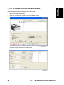
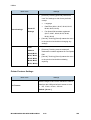
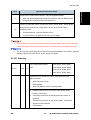
1.2.5 OPERATION PANELS
The operation panel for each machine of this series is different.
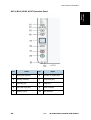
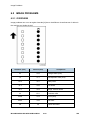
M133, M134, M162, M163, M145, M146, M164 Operation Panel
No.
Name
1
[Job Reset] Key
2
[Start] Key
3
Power Indicator
4
Alert Indicator
M145/M146/M147/M148/M149/M150/M151
1-14
SM
New Product Information
Product
Information
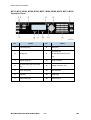
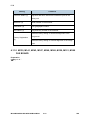
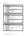
M134, M142, M165, M147 Operation Panel
No.
SM
Name
No.
Name
1
Document type key
6
[Number of copies] Key
2
Density Indicator
7
[Stop/Clear] Key
3
[Density] Key
8
[Start] Key
4
[ID Card Copy] Key
9
Power Indicator
5
Display (LCD)
10
Alert Indicator
1-15
M145/M146/M147/M148/M149/M150/M151
New Product Information
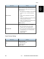
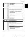
M135, M141, M143, M166, M148, M167, M149, M168, M150, M151, M169
Operation Panel
No.
1
Name
[Facsimile] Key
No.
8
Name
[Start] Key
[Scanner] Key
2
[Copy] Key
9
*M168, M169, M150, M151
only.
3
4
[Speed Dial] Key
[ID Card Copy/On Hook Dial]
Key
10
Power Indicator
11
Display Screen (LCD)
5
[User Tools] Key
12
Alert Indicator
6
[OK] Key
13
Scroll Keys
7
[Stop/Clear] Key
14
Number Keys
M145/M146/M147/M148/M149/M150/M151
1-16
SM
New Product Information
Product
Information
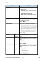
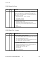
M191 Operation Panel
No.
Name
No.
Name
1
[ID Card Copy] Key
6
Power Indicator
2
[User Tools] Key
7
Display Screen (LCD)
3
[OK] Key
8
Alert Indicator
4
[Stop/Clear] Key
9
Scroll Keys
5
[Start] Key
10
Number Keys
Alert LEDs
Power LED
The Power LED remains OFF while the machine is turned off. The Power LED lights and remains
ON:
After the machine is turned on and enters the Ready mode
While the machine is in energy save mode
The Power LED FLASHES at 1 sec. intervals when
The PC is communicating with the machine
After picking up the handset to talk (M135, M141, and M143)
During copying
During printing
During scanning
During firmware update
Alert LED
The alert LED remains OFF while the printer is functioning normally or goes OFF after a problem
with the machine has been resolved.
SM
1-17
M145/M146/M147/M148/M149/M150/M151
New Product Information
The alert LED lights and remains ON:
When the machine malfunctions
Service Call errors (SC codes will appear on the 2-line and 2-digit display models.)
At toner end
Models that can detect toner end are as follows;
M145, M147, M148, M146
M149, M150, M151 (When Toner End Option is set for “Stop Printing".)
M135, M141, M143, M167, M168, M169 (Using genuine AIO and Toner End Option
is set to "Stop Printing".)
If the top cover or maintenance cover is open
When a paper or original jam occurs
When the paper tray runs out of paper
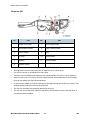
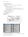
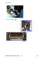
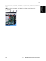
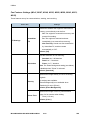
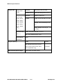
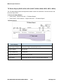
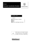
1.2.6 OVERVIEW
Paper Path
No.
Part
No.
Part
1
Paper Exit Sensor
7
Image Transfer Roller
2
Fusing Exit Roller
8
Registration Sensor
3
Exit Roller
9
Paper
4
Hot Roller
10
Feed Roller
5
Pressure Roller
11
By-pass Set Sensor
6
Drum
12
Paper End Sensor
When paper passes through the machine:
Paper (up to 150 sheets) is loaded in the paper tray. To feed the paper from the tray by the
M145/M146/M147/M148/M149/M150/M151
1-18
SM
New Product Information
The paper feeds between the nip of the rotating feed roller (10).
The registration sensor (8) detects the leading edge of the paper. This triggers the laser unit
above which writes the image onto the drum. The registration sensor will trigger an error if the
leading and trailing edge of the paper does not pass within the prescribed time. (The timing is
different, depending on the lengths of different paper sizes.)
The paper passes through the nip of the drum (6) and transfer roller (7). The transfer roller
pulls the toner image from the drum onto the paper.
The toner image is fused onto the paper when it passes through the nip of the hot roller (4)
and pressure roller (5).
The paper exit sensor (1) detects the leading edge and trailing edge of the paper. The sensor
will trigger a jam alert if the leading and trailing edge do not pass within the time prescribed for
the length of the paper (determined by the selected paper size).
Finally, the paper passes through the nip of the exit roller (3) and is stacked face-down on the
output tray.
When there is no paper in the tray, a feeler falls into a cutout in the bottom of the plate,
triggering the paper end sensor.
SM
The By-pass Set Sensor (11) detects when paper is set in the bypass tray.
1-19
M145/M146/M147/M148/M149/M150/M151
Product
Information
feed roller (10) is driven by the main motor.
New Product Information
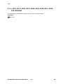
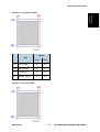
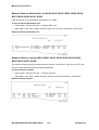
Drive Layout
No.
Part
No.
Part
1
Main Motor
5
Drum (inside AIO)
2
Gear Train
6
Hot Roller
3
Feed Roller
7
Paper Exit Roller
4
Paper Transport Roller
8
Paper Feed Clutch
The main motor (1) with gear train (2) drives Feed Roller (3), Paper Transport Roller (4), the drum
(5) in the AIO, Hot Roller (6) and Paper Exit Roller (7).
The Paper Feed Clutch (8) turns ON/OFF to control the Feed Roller.
M145/M146/M147/M148/M149/M150/M151
1-20
SM
New Product Information
Product
Information
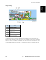
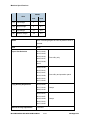
Image Writing
No.
Part
1
Registration Sensor
2
Polygon Mirror
3
Lenses, Mirrors
4
Drum
5
Image Transfer Roller
The registration sensor (1) detects the leading edge of the paper fed from the feed roller and
triggers the laser unit to fire the laser. The polygon mirror (2) shoots the laser through lenses and
mirrors (3) and onto the surface of the drum (4). Toner from the AIO forms the image on the drum.
The toner image is pulled from the surface on the drum onto the paper by the transfer roller (5).
SM
1-21
M145/M146/M147/M148/M149/M150/M151
Product
Information
New Product Information
INSTALLATION
R E V I S I O N H I S T O RY
Pa ge
Da te
Ad de d /U pd ate d /New
None
SM
1-1
M145/M146/M147/M148/M149/M150/M151
2. INSTALLATION
2.1 INSTALLATION REQUIREMENTS
2.1.1 INSTALLATION PROCEDURE
For instructions on unpacking the machine, installing the print cartridge (AIO), connection and
software installation, please refer to the operating instructions Quick Installation Guide.
2.1.2 ENVIRONMENT
Temperature
15°C to 25°C (59°F to 77°F)
Humidity
30% to 70% RH
1.
The machine can be used slightly out of the recommended ranges for temperature and
humidity ("Operational Range"), but for best performance use the temperature within the
recommended ranges.
2.
Ambient Illumination: Less than 2,000 lux (do not expose the AIO to strong light, especially
direct sunlight)
3.
Ventilation: 3 times/hr/person
4.
Do not put the machine in areas with sudden temperature changes. This includes:
5.
SM
Areas directly exposed to cool air from air conditioning
Areas directly exposed to heat from a heating system.
Do not put the machine in areas exposed to corrosive gas.
2-1
M145/M146/M147/M148/M149/M150/M151
Installation
Installation Requirements
Installation Requirements
6.
Do not install the machine at locations over 2,000 m (6,562 ft.) above sea level.
7.
Put the machine on a strong, level base. (Tilting towards any side must be no more than 3
mm.)
8.
Do not put the machine in areas with strong vibrations.
2.1.3 POWER REQUIREMENT
Power Source:
220 to 240V 50/60 Hz 5A or less (Asia/EU)
120V 60 Hz 8A or less (North America)
Check the machine installation and confirm the following important points:
Power plug fits tightly in the outlet.
Power plug is clean and free of dust.
The machine power plug is not connected to a shared source.
The machine should be properly grounded.
The power cord should be free and not wrapped around the leg of a chair or table, or bundled.
2.1.4 MACHINE LEVEL
Make sure that the machine is located on a flat surface.
Front to back
Within 5 mm (0.2") of level
Right to left
Within 5 mm (0.2") of level
M145/M146/M147/M148/M149/M150/M151
2-2
SM
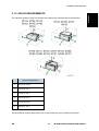
Installation Requirements
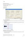
The machine should be used in a location that meets these minimum space requirements.
Space Requirements
A
45 cm (17.8 in.)
B
10 cm (4.0 in.)
C
20 cm (7.9 in.)
D
10 cm (4.0 in.)
E
40 cm (15.8 in.)
F
20 cm (7.9 in.)
There should be enough space at the front so the output tray can be opened and closed.
SM
2-3
M145/M146/M147/M148/M149/M150/M151
Installation
2.1.5 SPACE REQUIREMENTS
Installation Requirements
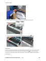
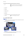
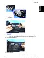
2.1.6 MOVING THE MACHINE
The machine is light, but be careful when you move it:
Always lift the printer by the inset handles on the left and right sides.
Leave the AIO in the machine while moving it.
Hold the machine horizontal while carrying it to prevent possible toner scatter inside the
machine.
Before transporting the printer to a remote location, re-pack it in its original box and packing
material.
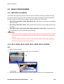
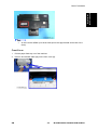
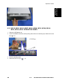
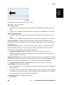
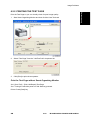
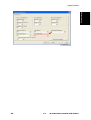
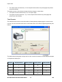
2.1.7 SMART ORGANIZING MONITOR
Smart Organizing Monitor is the utility that allows the operator to view and change the machine
settings for:
Paper size and type
System Settings:
Printer settings
Copy settings (for M134, M165, M147, M142, M166, M148, M135, M141, M143, M167, M149,
M168, M150, M151, M169, M191)
Fax settings (for M135, M141, M143, M167, M149, M168, M150, M151, M169)
Network settings (for M144, M163, M145, M142, M166, M148, M143, M168, M150, M151,
M167, M146, M164)
Scanner settings (for M166, M148, M143, M168, M150, M151, M169)
Printing reports and test pages
The Smart Organizing Monitor is provided with the machine on a CD-ROM and must be installed
together with the printer driver.
M145/M146/M147/M148/M149/M150/M151
2-4
SM
Installation Requirements
Here are some important features you should remember:
The refillable AIO units can be refilled by a service technician up to three times, depending on
usage. This extends the life of OPC drum.
Remaining toner amount is monitored using dot count for FiO, refillable printer, and TiO only.
Before loading paper, the paper size and paper type must be selected on the initial screen
(System Settings) of the smart Organizing Monitor. The same paper size and paper type must
also be selected with the printer driver at the start of a job. A mismatch error will occur if the
paper size/type settings in the Smart Organizing Monitor and the printer driver are not the
same.
The starter AIO (capacity: 1,000 prints for M133, M162, M144, M163, M134, M165, M142,
M166, M135, M141, M143, M167, M168, M191, M169 / 700 prints for M145, M147, M148,
M149, M150, M146, M151, M164) provided with the machine should be installed in the
machine at installation. After the starter AIO runs out of toner, it can be replaced with a new
AIO (capacity: 2,600/1,500 prints). This is especially important for the machines with fax
option; if the Toner End Option is switched off, customers may not be able to read incoming
fax messages.
SM
2-5
M145/M146/M147/M148/M149/M150/M151
Installation
2.1.8 IMPORTANT FEATURES
Installation
Installation Requirements
PREVENTIVE MAINTENANCE
R E V I S I O N H I S T O RY
Pa ge
Da te
Ad de d /U pd ate d /New
None
SM
2-1
M145/M146/M147/M148/M149/M150/M151
3. PREVENTIVE MAINTENANCE
3.1 CLEANING THE MACHINE
There are no PM parts for this machine. This section describes how the machine should be
cleaned.
3.1.1 BEFORE CLEANING
Always switch the machine off and unplug it before cleaning.
At least once a year, disconnect the power cable and clean the plug. Accumulated dust
causes a fire hazard.
Never use an organic solvent like benzene, thinner, acetone, etc. to clean the machine.
These materials can damage the plastic covers and other parts of the printer.
Make sure that the operators know how to clean the machine.
The machine should be cleaned periodically with a dry cloth.
If dry wiping is not sufficient, used a soft damp cloth with a neutral detergent and then dry
wipe.
Inspect the plug and clean away any dust or grime before reconnecting. Accumulated dust
can cause a fire hazard.
SM
3-1
M145/M146/M147/M148/M149/M150/M151
Preventive
Maintenance
Cleaning the Machine
Cleaning the Machine
3.1.2 ROUTINE CLEANING
1.
Remove the AIO and clean the inside surfaces of the printer with a dry cloth.
2.
Clean the exposure glass and white plate above the exposure glass of MF models with a soft
damp cloth, and then wipe it with a dry cloth.
3.
Clean the scanning glass of the ADF MF models (M166, M148, M135, M143, M167, M149,
M168, M150, M151, M169, and M191) with a soft damp cloth, and then wipe it with a dry
cloth.
For more details about cleaning, please refer to the machine operating instructions.
M145/M146/M147/M148/M149/M150/M151
3-2
SM
Preventive
Maintenance
Cleaning the Machine
REPLACEMENT AND ADJUSTMENTS
R E V I S I O N H I S T O RY
Pa ge
Da te
Ad de d /U pd ate d /New
None
SM
3-1
M145/M146/M147/M148/M149/M150/M151
4. REPLACEMENT AND ADJUSTMENTS
4.1 BEFORE YOU BEGIN
4.1.1 PRECAUTIONS
To prevent electrical shock, always switch the machine off and unplug it from its power
source.
Allow the machine to cool for at least 10 minutes. This allows the fusing unit to cool and
also allows time for the polygon mirror inside the laser unit to stop rotating.
4.1.2 SPECIAL TOOLS
There are no special tools required for disassembling the machine. However, you should have
these items:
Standard length hex screwdriver
Stubby hex screwdriver
Thin radio pliers
4.1.3 PRINTING THE TEST PAGE AND REPORTS
The table below is a quick reference to help you find how to print a report. Detailed descriptions of
these reports are provided in another section of this manual. (
page 5-7 "Utilities")
Keep these points in mind when you use this table:
The User Tools menu ("User Tools" key) is available for the M135, M141, M143, M167, M149,
M168, M150, M166, M148, M151, M164, and M191.
The Fax Maintenance menus are available for the M135, M141, M143, M167, M149, M168,
M150, M151, and M169 because only these have the fax feature.
The Smart Organizing Monitor is available for all machines for printing the Configuration Page
and Test Page.
No.
Report
Procedure
[User Tools] > "Report Print Set" > "Configuration
Page"
1
Configuration Page
Start SOM > User Tools > select "Configuration
Page" from the List/Test list > click [Print]
SM
4-1
M145/M146/M147/M148/M149/M150/M151
Replacement
and Adjustments
Before You Begin
Before You Begin
No.
Report
Procedure
*Service Mode > "Fax Maintenance" > "Report" >
2
Error Log History List
"Error Log History List"
After selection, the list is output after finishing the
SP mode with the “STOP” button.
[User Tools] > "Fax Features" > "Report Print Set" >
"Fax Journal"
3
Fax Journal
[User Tools] > "Report Print Set" > "Fax Journal"
Start SOM > User Tools > select "Fax Journal" from
the List/Test list > click [Print]
[User Tools] > "Report Print Set" > "Fax Speed Dial
List"
4
Fax Speed Dial List
Start SOM > User Tools > select "Fax Speed Dial
List" from the List/Test list > click [Print]
5
Fax Tx Standby File List
Start SOM > User Tools > select "Fax Tx
Standby
File List" from the List/Test list > click [Print]
*Service Mode > [Start] > "Fax Maintenance" >
6
Service Data List
"Report" > "Service Data List"
After selection, the list is output after finishing the
SP mode with the “STOP” button.
*Service Mode > "Fax Maintenance" > "Report" >
7
T.30 Protocol List
"T.30 Protocol List"
After selection, the list is output after finishing the
SP mode with the “STOP” button.
8
TX Standby File List
[User Tools] > "Report Print Set" > "TX Standby File
List"
[User Tools] > "Fax Features" > "Report Print Set" >
"TX Status Report"
9
TX Status Report
[User Tools] > "Report Print Set" > "TX Status
Report"
10
Test Page
[User Tools] > "Report Print Set" > "Test Page"
M145/M146/M147/M148/M149/M150/M151
4-2
SM
No.
Report
Procedure
Start SOM > User Tools > select "Test Page" from
the List/Test list > click [Print]
11
PC FAX Error Report
[User Tools] > “Fax Features” > “Report Print Set” >
“ PC FAX Error Report “
The report is output automatically in the following
cases
12
Power Failure Report
Power OFF during immediate transmission.
Power OFF during reception.
Unable to re-transmit after power OFF during
memory transmission.
13
Network Setting List
14
Scanner Journal
15
Scanner Dest. List
[User Tools]>"Print List/ Report" > "Network Setting
List"
[User Tools]>"Print List/ Report" > "Scanner
Journal"
[User Tools]>"Print List/ Report" > "Scanner Dest.
List"
The detailed procedure for entering the service mode is provided in the training materials
for these machines.
SM
4-3
M145/M146/M147/M148/M149/M150/M151
Replacement
and Adjustments
Before You Begin
Basic Procedures
4.2 BASIC PROCEDURES
4.2.1 BEFORE YOU BEGIN
This section describes the procedures that the service technician should know before servicing
the machine. Most of the parts of the machines in this series are identical and interchangeable.
However, please note that the main boards of these machines are not the same.
M133, M162, M144, M163, M145, M146, M164. Main board has no connectors for the flatbed
scanner or ADF.
M134, M141, M165, M147, M142. Main board has flat connectors for the flatbed scanner only
(not ADF).
M135, M143, M167, M149, M168, M150, M166, M148, M151, M169, M191. Main board has
flat connectors for both the flatbed scanner and ADF.
Before you service the machine, make sure that you know how to open the Service Mode
screen of the Smart Organizing Monitor. This procedure is not described in this service
manual.
For more details about how to open the Service Mode screen of the Smart Organizing
Monitor, refer to the service training material.
4.2.2 M133, M162, M144, M163, M145, M146, M164 COVERS
AIO
1.
Open the front cover [A].
2.
Grip the AIO [B] by its handle and pull it out of the machine.
3.
Place the AIO on a flat clean surface as shown below so the drum is not exposed to light.
M145/M146/M147/M148/M149/M150/M151
4-4
SM
Replacement
and Adjustments
Basic Procedures
An AIO can be refilled up to three times (this is the approximate service life of the
drum).
Front Cover
1.
Pull the paper feed tray out of the machine.
2.
Press in and release either peg on the front cover [A].
SM
4-5
M145/M146/M147/M148/M149/M150/M151
Basic Procedures
Right Cover
Preparation
Remove:
Front cover
Feed tray
1.
Screws [A]
2.
Stand the machine as shown.
3.
Locate the triangle marks that show you where the tab releases are located.
There are nine tabs on the right cover.
There are four tabs on the bottom.
There are two tabs on the front, one tab on the top, and two hooks on the back.
4.
Release the bottom tabs, then the front tabs.
5.
Open the cover front to back with attention to the rest of the tabs and hooks.
6.
Right Cover
M145/M146/M147/M148/M149/M150/M151
4-6
SM
Replacement
and Adjustments
Basic Procedures
Left Cover
Preparation
Remove:
Front cover
Feed tray
1.
Screws [A]
2.
Stand the machine as shown.
3.
Locate the triangle marks that show you where the tab releases are located.
There are twelve tabs on the left cover.
There are four tabs on the bottom.
There are two tabs on the front, three tabs on the top, and three tabs on the back.
4.
Release the bottom tabs, then the front tabs.
5.
Open the cover front to back with attention to the rest of the tabs.
SM
4-7
M145/M146/M147/M148/M149/M150/M151
Basic Procedures
6.
Left Cover
Top Cover
Preparation
Remove:
Front Cover
Right Cover
Left Cover
Top Cover (
x 4)
M145/M146/M147/M148/M149/M150/M151
4-8
SM
Rear Cover
The rear cover does not require removal unless the PSU requires replacement. (
page 4-70
"PSU")
4.2.3 M134, M141, M165, M147, M142 COVERS, PLATEN COVER,
FLATBED UNIT
Platen Cover
Raise the platen cover and then lift it straight up to remove it.
AIO
1.
Open the front cover [A].
2.
Grip the AIO [B] by its handle and pull it out of the machine.
3.
Place the AIO on a flat clean surface as shown below so the drum is not exposed to light.
SM
4-9
M145/M146/M147/M148/M149/M150/M151
Replacement
and Adjustments
Basic Procedures
Basic Procedures
An AIO can be refilled up to three times (this is the approximate service life of the
drum).
Front Cover
1.
Pull the paper feed tray out of the machine.
2.
Press in and release either peg on the front cover [A].
M145/M146/M147/M148/M149/M150/M151
4-10
SM
Replacement
and Adjustments
Basic Procedures
Right Cover
Preparation
Remove:
AIO
Front cover
1.
Screws and hooks [A].
2.
Release the hook on the bottom [A].
3.
Open the cover front to back while paying attention to the hooks [B] at the back.
4.
Right Cover
SM
4-11
M145/M146/M147/M148/M149/M150/M151
Basic Procedures
Left Cover
Preparation
Remove:
Handset
AIO
Front Cover
1.
Screws [A]
2.
Stand the machine as shown below.
3.
Release the hooks on the bottom [A].
4.
Release the hooks on the front [B].
M145/M146/M147/M148/M149/M150/M151
4-12
SM
Replacement
and Adjustments
Basic Procedures
5.
Take the left cover [A] off from the front to the back. (
x 1)
Rear Cover
The rear cover does not require removal unless the PSU requires replacement. (
page 4-70
"PSU")
Left Hinge
The left hinge does not require removal unless it must be replaced.
Preparation
Remove:
Left Cover.
Feed Tray.
AIO.
1.
Release the spring [A].
SM
4-13
M145/M146/M147/M148/M149/M150/M151
Basic Procedures
2.
Stand the machine as shown below.
3.
Release the hook [A].
4.
Release the hook [A] to separate the boss [B] from the flatbed unit slightly.
5.
Release the hook [C] to detach the guide which connects to the hinge.
6.
Without step No. 4, the hook [C] cannot release due to the boss [B].
Detach the hinge [A] from the guide [B].
M145/M146/M147/M148/M149/M150/M151
4-14
SM
Replacement
and Adjustments
Basic Procedures
7.
Bend and release the joint part with a screwdriver to detach the hinge.
8.
SM
Bend the hinge carefully not to break it.
Left Hinge
4-15
M145/M146/M147/M148/M149/M150/M151
Basic Procedures
Flatbed Scanner Unit
Preparation
Remove:
Platen Cover
AIO
Front Cover
Right Cover
Left Cover
Detach the Left Hinge from the Guide
1.
Disconnect the FFCs and the connector on the main board. (
x 2,
x 1).
To disconnect the FFC on the left corner, remove the screw at the back to move the
cover out. (The cover is also hooked at the bottom, so release it.)
2.
Raise the cover as shown below and pull it out of the hinges.
3.
Flatbed Scanner Unit.
M145/M146/M147/M148/M149/M150/M151
4-16
SM
Replacement
and Adjustments
Basic Procedures
Inner Cover
Preparation
Remove:
Front Cover
Right Cover
Left Cover
Detach ADF / Flatbed Unit from the machine
Inner Cover [A] (
SM
x 4)
4-17
M145/M146/M147/M148/M149/M150/M151
Basic Procedures
4.2.4 M135, M143, M167, M149, M168, M150, M166, M148, M191,
M151, M169 COVERS, FLATBED UNIT, ADF
Original Feed Tray
1.
Open the covers [A] and keep on.
2.
Press in and release either peg on each end of the tray.
AIO
1.
Open the front cover [A].
2.
Grip the AIO [B] by its handle and pull it out of the machine.
3.
Place the AIO on a flat clean surface as shown below so the drum is not exposed to light.
M145/M146/M147/M148/M149/M150/M151
4-18
SM
Replacement
and Adjustments
Basic Procedures
An AIO can be refilled up to three times (this is the approximate service life of the
drum).
Front Cover
1.
Pull the paper feed tray out of the machine.
2.
Press in and release either peg on the front cover [A].
SM
4-19
M145/M146/M147/M148/M149/M150/M151
Basic Procedures
Right Cover
Preparation
Remove:
AIO
Front Cover
1.
Screws and hooks [A].
2.
Release the hook on the bottom [A].
3.
Open the right cover front to back while paying attention to the hooks [B] at the back.
4.
Right Cover
M145/M146/M147/M148/M149/M150/M151
4-20
SM
Replacement
and Adjustments
Basic Procedures
Left Cover
Preparation
Remove:
Handset
AIO
Front Cover
1.
Screws [A]
2.
The screws [A] that hold the handset.
SM
4-21
M145/M146/M147/M148/M149/M150/M151
Basic Procedures
3.
Stand the machine as shown below.
4.
Release the hooks on the bottom [A]
5.
Release the hooks on the front [B].
6.
Put the left cover [A] off from the front to the back as shown below. (
M145/M146/M147/M148/M149/M150/M151
4-22
x 1)
SM
Left Hinge
The left hinge does not require removal unless it must be replaced.
Preparation
Remove:
Left Cover.
Feed Tray.
AIO.
1.
Release the spring [A].
2.
Stand the machine as shown below.
3.
Release the hook [A].
4.
Release the hook [A] to separate the boss [B] from the flatbed unit slightly.
5.
Release the hook [C] to detach the guide which connects to the hinge.
SM
4-23
M145/M146/M147/M148/M149/M150/M151
Replacement
and Adjustments
Basic Procedures
Basic Procedures
Without step No. 4, the hook [C] cannot release due to the boss [B].
6.
Detach the hinge [A] from the guide [B].
7.
Bend and release the joint part with a screwdriver to detach the hinge.
8.
Bend the hinge carefully not to break it.
Left Hinge
M145/M146/M147/M148/M149/M150/M151
4-24
SM
Replacement
and Adjustments
Basic Procedures
Rear Cover
The rear cover does not require removal unless the PSU requires replacement (
page 4-70
"PSU")
ADF/Flatbed Unit
Preparation
Remove:
AIO
Front Cover
Right Cover
Left Cover
Detach the Left Hinge from the Guide
1.
Disconnect FFCs and connectors [A]. (
2.
Disconnect the ground wire [B]. (
x 2,
x 3)
x 1)
To disconnect the FFCs and the ground wire on the corner, remove the screw at the
back to move the cover out. (The cover is also hooked at the bottom, so release it.)
3.
SM
Raise the cover as shown below and pull it out of the hinges.
4-25
M145/M146/M147/M148/M149/M150/M151
Basic Procedures
4.
Pull the ADF out of the flatbed unit.
5.
Pull the harnesses through the rear corner of the flatbed unit.
A latch will get stuck when you try to pull the ADF out. So tilt the ADF backward to let
it out while pulling.
6.
ADF / Flatbed unit.
Inner Cover
Preparation
M145/M146/M147/M148/M149/M150/M151
4-26
SM
Basic Procedures
Front Cover
Right Cover
Left Cover
Detach the ADF / Flatbed Unit from the machine
Inner Cover [A] (
Replacement
and Adjustments
Remove:
x 4)
4.2.5 REMOVING THE FUSING UNIT
Preparation
M133, M162, M144,
M163, M145, M146,
M164
AIO
Front cover
Right cover
Top cover
(
page 4-4 "M133, M162, M144, M163, M145, M146,
M164 Covers")
M134, M141, M165,
(
M147, M142
Platen Cover, Flatbed Unit")
AIO
Front cover
Right cover
Inner cover
SM
page 4-9 "M134, M141, M165, M147, M142 Covers,
4-27
M145/M146/M147/M148/M149/M150/M151
Basic Procedures
M135, M143, M167,
(
M149, M168, M150,
M166, M148, M191, M151, M169 Covers, Flatbed Unit,
M166, M148, M169,
ADF")
M151, M191
AIO
Front cover
Right cover
Inner cover
1.
Rear cover [A]. (
page 4-18 "M135, M143, M167, M149, M168, M150,
x2,
x2)
The red arrows in the picture above indicate where the hooks are.
2.
Rear door [A] (peg x 2)
3.
Exit roller unit [A]
M145/M146/M147/M148/M149/M150/M151
4-28
SM
Replacement
and Adjustments
Basic Procedures
4.
Screws [A] on the right side.
5.
Ground wire [B]. (
6.
Release the spring [C].
7.
Screw [A] on the top side.
8.
Disconnect the fusing unit harness [A].
SM
x 1)
4-29
M145/M146/M147/M148/M149/M150/M151
Basic Procedures
9.
Fusing Unit [A] (
x 6,
x 1).
M145/M146/M147/M148/M149/M150/M151
4-30
SM
Replacement
and Adjustments
Basic Procedures
4.2.6 UTILITIES AND MAINTENANCE
This is a quick summary of the utilities that are available for machine servicing.
M135
No.
Function
Start From
M133
M134
M141
M162
M165
M143
M144
M147
M167
M163
M142
M149
M145
M166
M168
M146
M148
M150
M164
M191
M151
M169
1
Fax Maintenance
Operation Panel
No
No
Yes
2
Fax Test
Operation Panel
No
No
Yes
3
Engine Maintenance
SOM Service Mode
Yes
Yes
Yes
4
Counter Information
Yes
Yes
Yes
5
Error History
Yes
Yes
Yes
Screen
1. To start Fax Maintenance
1.
Make sure the machine is in the Ready mode.
2.
Enter the service mode. Ask your supervisor if you don’t know how to enter this mode.
2. To start Fax Test
1.
Switch the machine on.
2.
With the machine in Ready mode, press [Copy/Fax].
3. Engine Maintenance, Counter Information, Error History
Items 3, 4, and 5 in the table above are on the Service Mode screen of the Smart Organizing
Monitor.
1.
Open Smart Organizing Monitor.
2.
Enter the service mode to display the Service Mode screen.
There are other important features in the Smart Organizing Monitor that are used during servicing:
Printing a Test Page
Firmware update
Releasing the machine after a fatal fusing error
Resetting the machine after correcting a fatal fusing error
More details about these utilities are available in another section of this service manual. (
page
5-7 "Utilities")
SM
4-31
M145/M146/M147/M148/M149/M150/M151
Basic Procedures
The M135, M141, M143, M167, M149, M168, M150, M166, M148, M151, M169, and
M191 have a User Tools key that opens the User Tools menus.
Many items in these menus duplicate the tasks that can be performed with the Smart
Organizing Monitor.
Please remember that these User Tools menus are available with the M135, M141, M143,
M167, M149, M168, M150, M166, M148, M151, M169, and M191 only. (The M133, M162,
M144, M163, M145, M134, M165, M147, M142, M146, and M164 do not have a User
Tools key on their operation panels.)
M145/M146/M147/M148/M149/M150/M151
4-32
SM
4.3 OPERATION PANELS
4.3.1 M133, M162, M144, M163, M145, M146, M164 OPERATION
PANEL
Preparation
Top cover (
1.
Lay the top cover upside down.
2.
Operation panel PCB (
page 4-4 "M133, M162, M144, M163, M145, M146, M164 Covers")
x 2).
4.3.2 M134, M165, M147, M142 OPERATION PANEL / PANEL COVER
Operation Panel
1.
Raise the platen and then lift it straight up to remove it.
2.
Insert a screwdriver into the hole and press it downward to take the latch off as shown [1]
while pushing firmly toward the front of the machine [2] until you hear it click and release.
SM
4-33
M145/M146/M147/M148/M149/M150/M151
Replacement
and Adjustments
Operation Panels
Operation Panels
3.
Lift the operation panel straight up to disconnect the hooks at three points.
4.
Turn the operation panel over, and then disconnect the flat cable (
x 1).
Panel Cover
Panel Cover [A] can be detached in the same manner as the M135, M141, M143, M167, M149,
M168, M150, M166, M148, M151, M169, M191 Operation Panel (
page 4-35 "M135, M141,
M143, M167, M149, M168, M150, M166, M148, M151, M169, M191 Operation Panel") without
disconnection.
M145/M146/M147/M148/M149/M150/M151
4-34
SM
Replacement
and Adjustments
Operation Panels
4.3.3 M135, M141, M143, M167, M149, M168, M150, M166, M148,
M151, M169, M191 OPERATION PANEL
1.
Raise the ADF/flatbed unit.
2.
Insert a flat-blade screwdriver while pushing either side of the latches [A] to release the hooks
[B]. (
x 3)
3.
Pull the operation panel.
4.
Disconnect the FFC [A]. (
SM
x 1)
4-35
M145/M146/M147/M148/M149/M150/M151
Operation Panels
5.
Operation Panel
M145/M146/M147/M148/M149/M150/M151
4-36
SM
Replacement
and Adjustments
Laser Unit
4.4 LASER UNIT
4.4.1 REMOVING THE LASER UNIT
There are no serviceable parts inside the laser unit. Never attempt to disassemble the
laser unit and then reinstall it in the machine.
Preparation
M133, M162, M144, M163, M145, M146, M164
(
page 4-4 "M133, M162,
M144, M163, M145, M146, M164
Covers")
AIO
Left Cover
Top Cover
M134, M141, M165, M147, M142
(
page 4-9 "M134, M141, M165, M147, M142 Covers, Platen Cover, Flatbed Unit")
AIO
Left Cover
Flatbed Unit
Inner Cover
M135, M143, M167, M149, M168, M150, M166, M148, M151, M169, M191
(
page 4-18 "M135, M143, M167, M149, M168, M150, M166, M148, M191, M151,
M169 Covers, Flatbed Unit, ADF")
AIO
Left Cover
ADF/Flatbed Unit
Inner Cover
1.
SM
Detach the screws [circles] and the connectors [arrows]. (
4-37
x 5,
x 3)
M145/M146/M147/M148/M149/M150/M151
Laser Unit
2.
Laser Unit
M145/M146/M147/M148/M149/M150/M151
4-38
SM
4.4.2 AFTER REPLACING THE LASER UNIT
After replacing the laser unit, print the Test Page and check the position of the image area on the
page.
1.
Start Smart Organizing Monitor.
2.
Click the User Tool tab (1), open the List/Test pull-down list (2), and then click [Print]. The Test
Page prints.
3.
SM
Check the margins of the image area to see the width of the margins are satisfactory.
4-39
M145/M146/M147/M148/M149/M150/M151
Replacement
and Adjustments
Laser Unit
Laser Unit
Margin
Width (mm)
[A]
Left
4.2
[B]
Right
4.2
[C]
Leading
4.2
[D]
Trailing
4.2
4.
Enter the service mode and display the Service Mode screen.
5.
Adjust the Factory Registration settings (10) to adjust the margins.
Horizontal. Shifts the image left or right to adjust the left/margins.
Vertical. Shifts the image up or down to adjust the top/bottom margins.
M145/M146/M147/M148/M149/M150/M151
4-40
SM
Replacement
and Adjustments
Paper Pass
4.5 PAPER PASS
This section describes how to remove these items:
Friction Pad
Paper Feed Roller
Image Transfer Roller
Exit Roller
Preparation
These items must be removed before doing any procedure in this section. Do this now before
going to any other part of this section.
M133, M162, M144, M163, M145, M146, M164
AIO
(
page 4-4 "M133, M162, M144, M163, M145, M146,
M164 Covers")
Front Cover
Top Cover
Left Cover
Main Board
Laser Unit
(
page 4-37 "Removing the Laser Unit")
M134, M165, M147, M142, M141
AIO
(
page 4-9 "M134, M141, M165, M147, M142 Covers,
Platen Cover, Flatbed Unit")
Front Cover
Left Cover
Platen Cover
Flatbed Unit
Inner Cover
Main Board
Fax Board (For M141)
Laser Unit
SM
(
page 4-37 "Removing the Laser Unit")
4-41
M145/M146/M147/M148/M149/M150/M151
Paper Pass
M135, M143, M167, M149, M168, M150, M166, M148, M151, M169, M191
AIO
(
page 4-18 "M135, M143, M167, M149, M168, M150,
M166, M148, M191, M151, M169 Covers, Flatbed Unit,
ADF")
Front Cover
Top Cover
Left Cover
Flatbed Unit, ADF
Inner Cover
Main Board
Fax Board (For M135, M143, M167, M149, M168, M150, M151, M169)
Laser unit
(
page 4-37 "Removing the Laser Unit")
4.5.1 PAPER FEED ROLLER
To detach the paper feed roller, the paper feed clutch that is attached to the end of the
paper feed roller shaft must be removed first.
1.
Gear cover [A] (
2.
x 8).
One of the screws is hidden at the back of the main motor cover [B].
Detach the gear [A] to take the paper feed clutch [B] off.
M145/M146/M147/M148/M149/M150/M151
4-42
SM
Replacement
and Adjustments
Paper Pass
3.
Release the right end of the shaft [A].
To release the shaft, pull the shaft [1] to bend it while pushing to the left [2] to let the
latch in the area of the film [B] out from the notch which is carved in the shaft.
4.
Slide the paper feed roller out.
5.
Paper Feed Roller.
SM
4-43
M145/M146/M147/M148/M149/M150/M151
Paper Pass
4.5.2 FRICTION PAD
1.
Pull the feed tray out.
2.
Detach the friction pad [A] from the feed tray. (
3.
Friction Pad
M145/M146/M147/M148/M149/M150/M151
4-44
x 2).
SM
Paper Pass
Replacement
and Adjustments
4.5.3 PAPER TRANSPORT ROLLER
Preparation
Gear Cover (
1.
Gear [A] on the paper transport roller shaft.
2.
Open the roller cover [A].
3.
E-ring [A] on the left side end of the shaft.
4.
Slide the shaft to the left and release the right end. Then pull it out.
SM
page 4-42 "Paper Feed Roller")
4-45
M145/M146/M147/M148/M149/M150/M151
Paper Pass
5.
Paper Transport Roller
M145/M146/M147/M148/M149/M150/M151
4-46
SM
4.5.4 IMAGE TRANSFER ROLLER
Preparation
Laser Unit (
1.
Before you remove the Image transfer roller:
page 4-37 "Removing the Laser Unit")
The collar on the right end of the roller [A] is black.
The collar on the left end of the roller [B] is white.
The Image transfer roller must be installed the same way, with the black collar on the
right and the white collar on the left.
2.
The collars are set in grooves. Pull up on both ends of the Image transfer roller [A] and [B] to
free the collars.
3.
Remove the spring from the left end [A] and right end [B] to prevent the springs from getting
lost.
SM
4-47
M145/M146/M147/M148/M149/M150/M151
Replacement
and Adjustments
Paper Pass
Paper Pass
If you are replacing the Image transfer roller, keep these springs. New springs may
not be provided with the new Image transfer roller.
Re-installation
1.
Clean the charge plates [A] on the side where the right end of the roller will be re-installed.
The spring will be re-attached over the peg [B].
2.
After re-installing the Image transfer roller, press and release the Image transfer roller several
times to confirm that the roller bounces up and down evenly.
M145/M146/M147/M148/M149/M150/M151
4-48
SM
If the center or either end of the roller does not bounce up and down freely, this means
that one or both springs at the ends of the roller are not installed correctly.
Remove the Image transfer roller and re-install it. Make sure each spring is set onto the
metal peg on both sides.
4.5.5 PAPER EXIT ROLLER
See “Removing the Fusing Unit”. (
SM
page 4-37 "Removing the Laser Unit")
4-49
M145/M146/M147/M148/M149/M150/M151
Replacement
and Adjustments
Paper Pass
Sensors
4.6 SENSORS
4.6.1 REGISTRATION SENSOR
Preparation
Remove:
AIO
Feed Tray
1.
Raise the machine so you can see the bottom.
2.
Bottom Cover [A] (
3.
Registration Sensor [A] (
x 4).
x 1,
M145/M146/M147/M148/M149/M150/M151
x 3)
4-50
SM
Replacement
and Adjustments
Sensors
4.6.2 PAPER END SENSOR
Preparation
Remove:
AIO.
Feed Tray.
Bottom Cover (
page 4-50 "Registration Sensor")
Paper End Sensor [A] (
x 1,
x 3)
4.6.3 BYPASS SET SENSOR
Preparation
Remove:
AIO
Left Cover
1.
Stand the machine as shown below.
2.
Release the hooks while keeping the feeler [A] out.
SM
4-51
M145/M146/M147/M148/M149/M150/M151
Sensors
3.
To release the hooks, access with a screwdriver from the indicated area [B].
Bypass Set Sensor (
x 1)
4.6.4 PAPER EXIT SENSOR
Preparation
Remove:
Left Cover
Rear Door
Fusing Exit Roller Unit
Paper Exit Sensor [A] (
x 1,
x 3).
M145/M146/M147/M148/M149/M150/M151
4-52
SM
Replacement
and Adjustments
Main Motor
4.7 MAIN MOTOR
4.7.1 REMOVING THE MAIN MOTOR
Preparation
M133, M162, M144, M163, M145, M146, M164
AIO
(
page 4-4 "M133, M162, M144, M163, M145, M146,
M164 Covers")
Left Cover
Main Board
Gear Cover
M134, M165, M147, M142, M141
AIO
(
page 4-9 "M134, M141, M165, M147, M142
Covers, Platen Cover, Flatbed Unit")
Left Cover
Main Board
Fax Board (M141 only)
Gear Cover
M135, M143, M167, M149, M168, M150, M166, M148, M151, M169, M191
AIO
(
page 4-18 "M135, M143, M167, M149, M168,
M150, M166, M148, M191, M151, M169 Covers,
Flatbed Unit, ADF")
Left Cover
Main Board
Fax Board (For M135, M143, M167, M149, M168, M150, M151, M169)
Gear Cover
1.
All of the gears [A] (
2.
Screws [B]
SM
x 1)
4-53
M145/M146/M147/M148/M149/M150/M151
Main Motor
3.
Main Motor (
x 1)
M145/M146/M147/M148/M149/M150/M151
4-54
SM
4.7.2 REINSTALLING THE MAIN MOTOR
1.
Match boss [A] with the hole [B] in the gear cover. This aligns the holes correctly for
re-attachment of the motor to the gear cover.
4.8 CLUTCH
4.8.1 PAPER FEED CLUTCH
See “Paper Feed Roller”. (
SM
page 4-42 "Paper Feed Roller")
4-55
M145/M146/M147/M148/M149/M150/M151
Replacement
and Adjustments
Clutch
Switches
4.9 SWITCHES
4.9.1 FRONT DOOR SWITCH
Preparation
M133, M162, M144, M163, M145, M146, M164
(
page 4-4 "M133, M162, M144, M163, M145, M146, M164 Covers")
AIO
Front cover
Left cover
M134, M141, M165, M147, M142
(
page 4-9 "M134, M141, M165, M147, M142 Covers, Platen Cover, Flatbed Unit")
AIO
Front cover
Left cover
M135, M143, M167, M149, M168, M150, M166, M148, M151, M169, M191
(
page 4-18 "M135, M143, M167, M149, M168, M150, M166, M148, M191, M151,
M169 Covers, Flatbed Unit, ADF")
AIO
Front cover
Left cover
1.
Disconnect the harness [A] on the main board.
M145/M146/M147/M148/M149/M150/M151
4-56
SM
Replacement
and Adjustments
Switches
2.
Screw [A]
3.
Front Door Switch (
SM
x 2)
4-57
M145/M146/M147/M148/M149/M150/M151
Switches
4.9.2 INTERLOCK SWITCH
Preparation
M133, M162, M144, M163, M145, M146, M164
Main Board
(
page 4-65 "M133, M162, M144, M163, M145, M146,
M164 Main Board")
M134, M141
Main Board
(
page 4-66 "M134, M141, M165, M147, M142 Main
Board")
M135, M143, M167, M149, M168, M150, M166, M148, M151, 169, M191
Main Board
Interlock Switch [A] (
(
page 4-67 "M135, M143, M167, M149, M168, M150,
M166, M148, M151, M169, M191 Main Board")
x 1,
x 2)
M145/M146/M147/M148/M149/M150/M151
4-58
SM
Replacement
and Adjustments
Fusing Unit
4.10 FUSING UNIT
This section describes how to remove these items:
Exit Roller
Pressure Roller
Fusing Lamp
Thermostat
Thermistor
Ground Plate
4.10.1 SEPARATING THE FUSING UNIT
Preparation
Fusing unit (
1.
Release the springs [A].
2.
Arms [B] on both ends.
page 4-27 "Removing the Fusing Unit")
Two strong springs on either side of the fusing unit [A] keep the soft pressure roller
compressed against the hot roller. These springs must be removed in order to
disassemble the fusing unit.
3.
Screws [A].
4.
Ground plate [B]. (
SM
x 2)
4-59
M145/M146/M147/M148/M149/M150/M151
Fusing Unit
5.
Separate the Fusing Unit.
Be sure to prevent the springs or pawls [A] from falling off and becoming lost.
M145/M146/M147/M148/M149/M150/M151
4-60
SM
4.10.2 FUSING EXIT ROLLER
Preparation
Detach the fusing exit roller unit from the machine (
1.
Bend the shaft carefully to take the left end [A] off.
2.
Turn the roller until you see the flat side of the roller shaft facing up, and pull the right side [B]
page 4-27 "Removing the Fusing Unit")
out.
4.10.3 PRESSURE ROLLER
Preparation
Fusing Unit (
Separate the top and bottom halves of the fusing unit (
page 4-27 "Removing the Fusing Unit")
page 4-59 "Separating the Fusing
Unit")
1.
Pull the pressure roller [A] out as shown.
2.
Lay the roller on a flat clean surface.
Avoid touching the surface of the pressure roller with your fingers or bare hands. If the
roller requires cleaning, wipe the surface with a clean dry cloth.
SM
4-61
M145/M146/M147/M148/M149/M150/M151
Replacement
and Adjustments
Fusing Unit
Fusing Unit
4.10.4 HOT ROLLER, FUSING LAMP
Preparation
Fusing Unit (
Separate the top and bottom halves of the fusing unit (
page 4-27 "Removing the Fusing Unit")
page 4-59 "Separating the Fusing
Unit")
1.
Screws [A].
2.
Lift both ends of the hot roller and remove it.
Avoid touching the surface of the hot roller with your fingers or bare hands.
If the roller requires cleaning, wipe the surface with a clean dry cloth.
3.
Pull the fusing lamp slowly out of the left end of the hot roller.
4.
Lay the fusing lamp on a clean flat surface.
M145/M146/M147/M148/M149/M150/M151
4-62
SM
Replacement
and Adjustments
Fusing Unit
Avoid touching the surface of the fusing lamp with your fingers or bare hands. The oil
from fingerprints or hand smudges can cause the surface of the fusing lamp to heat
unevenly.
If the fusing lamp requires cleaning, wipe the surface with a clean cloth dampened with
alcohol, and then dry wipe with a soft clean cloth.
4.10.5 THERMOSTAT
Preparation
Fusing Unit (
1.
Cover [A] (
2.
Thermostat [B] (
page 4-27 "Removing the Fusing Unit")
x 1)
x 2).
Always replace a blown thermostat with a new one.
Never attempt to reset a blown thermostat by manipulating the edges of the black cover
with a screw driver.
Resetting a thermostat manually could cause a failure to detect overheating in the fusing
unit and cause a fire hazard.
SM
4-63
M145/M146/M147/M148/M149/M150/M151
Fusing Unit
4.10.6 THERMISTOR
Two thermistors are installed in this machine.
Preparation
Fusing Unit (
Thermistor [A] (
page 4-27 "Removing the Fusing Unit")
x 1 each)
Before removing each thermistor, remember how the thermistors touch the hot roller. The
tips are pointing upward.
4.10.7 GROUND PLATE
See “Separating the Fusing Unit”. (
page 4-59 "Separating the Fusing Unit")
M145/M146/M147/M148/M149/M150/M151
4-64
SM
4.11 PCB
Before board replacement, enter the SP mode to output reports (Service Date List, Fax
Dial List, and Fax Speed Dial List). Refer to these reports when making settings after
replacement.
4.11.1 M133, M162, M144, M163, M145, M146, M164 MAIN BOARD
Preparation (
page 4-4 "M133, M162, M144, M163, M145, M146, M164 Covers")
Left Cover
1.
Disconnect all of the harnesses on the main board.
To access the components at the left corner of the board, you need to remove the
screw on the back cover to let it move out. (The cover is also hooked at the bottom,
so release it.)
2.
SM
Main Board (
x 4)
4-65
M145/M146/M147/M148/M149/M150/M151
Replacement
and Adjustments
PCB
PCB
Re-installation
If the main board has been replaced, be sure to do the procedures for after replacing a main
board. (
page 4-68 "
M145/M146/M147/M148/M149/M150/M151
4-66
SM
PCB
4.11.2 M134, M141, M165, M147, M142 MAIN BOARD
Preparation (
page 4-9 "M134, M141, M165, M147, M142 Covers, Platen Cover, Flatbed Unit")
Left Cover
1.
Disconnect all of the harnesses on the main board.
To access the components at the left corner of the board, you need to remove the
screw on the back cover to let it move out. (The cover is also hooked at the bottom,
so release it.)
2.
Main Board (
x 4)
Re-installation
If the main board has been replaced, be sure to do the procedures for after replacing a main
board. (
SM
page 4-68 "
4-67
M145/M146/M147/M148/M149/M150/M151
Replacement
and Adjustments
After Replacing the Main Board")
PCB
After Replacing the Main Board")
4.11.3 M135, M143, M167, M149, M168, M150, M166, M148, M151,
M169, M191 MAIN BOARD
Preparation (
page 4-18 "
M145/M146/M147/M148/M149/M150/M151
4-68
SM
PCB
Replacement
and Adjustments
M135, M143, M167, M149, M168, M150, M166, M148, M191, M151, M169 Covers, Flatbed Unit,
ADF")
Left Cover
1.
Disconnect all of the harnesses on the main board.
2.
Ground wire [A] (
x 1)
To access the components at the left corner of the board, you need to remove the
screw on the back cover to let it move out. (The cover is also hooked at the bottom,
so release it.)
3.
Main Board (
x 3)
Re-installation
When you re-install the board, be sure to re-connect the ground wires at the upper left corner.
If the main board has been replaced, be sure to do the procedures for after replacing a main
board. (
SM
page 4-68 "
4-69
M145/M146/M147/M148/M149/M150/M151
PCB
After Replacing the Main Board")
M145/M146/M147/M148/M149/M150/M151
4-70
SM
4.11.4 AFTER REPLACING THE MAIN BOARD
Do the procedures below after replacing the main board.
1.
Start Smart Organizing Monitor.
2.
Enter the service mode to display the Service Mode screen.
3.
Do these settings on the service mode screen.
SM
4-71
M145/M146/M147/M148/M149/M150/M151
Replacement
and Adjustments
PCB
PCB
Setting
Fuser SC Detect (1)
Comment
Signals a fatal error after three consecutive jams in the
fusing unit.
Serial No. (2)
Serial number of the machine.
Destination (3)
Your geographic location.
PnP Name (4)
Plug-and-Play number of the machine.
Restores factory setting for horizontal alignment of the
Factory Registration
image area.
(5)
Restores factory setting for vertical alignment of the image
area.
4.11.5 M135, M141, M143, M167, M149, M168, M150, M151, M169
FAX BOARD
Preparation
(
page 4-18 "
M145/M146/M147/M148/M149/M150/M151
4-72
SM
PCB
ADF")
(
page 4-9 "M134, M141, M165, M147, M142 Covers, Platen Cover, Flatbed Unit")
Left Cover
Fax Board (
SM
x 3,
x 1,
x 1)
4-73
M145/M146/M147/M148/M149/M150/M151
Replacement
and Adjustments
M135, M143, M167, M149, M168, M150, M166, M148, M191, M151, M169 Covers, Flatbed Unit,
PCB
4.11.6 M135, M141, M143, M167, M149, M168, M150, M151, M169
FAX SPEAKER
The fax speaker is installed on the other side of the fax board (right side).
Preparation
(
page 4-18 "
M145/M146/M147/M148/M149/M150/M151
4-74
SM
PCB
ADF")
page 4-9 "M134, M141, M165, M147, M142 Covers, Platen Cover, Flatbed Unit")
(
Right Cover
Inner Cover
Fax Speaker (
x 2,
x 1,
x 1)
4.11.7 PSU
Preparation
M133, M162, M144, M163, M145, M146, M164
Front Cover
(
page 4-4 "M133, M162, M144, M163, M145, M146,
M164 Covers")
Right Cover
Top Cover
M134, M141, M165, M147, M142
Front Cover
(
page 4-9 "M134, M141, M165, M147, M142 Covers,
Platen Cover, Flatbed Unit")
Right Cover
Inner Cover
M135, M143, M167, M149, M168, M150, M166, M148, M151, M169, M191
SM
4-75
M145/M146/M147/M148/M149/M150/M151
Replacement
and Adjustments
M135, M143, M167, M149, M168, M150, M166, M148, M191, M151, M169 Covers, Flatbed Unit,
PCB
Front Cover
(
page 4-18 "M135, M143, M167, M149, M168, M150,
M166, M148, M191, M151, M169 Covers, Flatbed Unit,
ADF")
Right Cover
Inner Cover
x6,
1.
Separate the PSU cover [A] slightly from the machine. (
2.
Disconnect the harnesses on the PSU to separate it completely.
3.
PSU (
x1)
x 4)
M145/M146/M147/M148/M149/M150/M151
4-76
SM
Replacement
and Adjustments
PCB
4.11.8 H.V.P.P.
Preparation
M133, M162, M144, M163, M145, M146, M164
Right cover
(
page 4-4 "M133, M162, M144, M163, M145, M146,
M164 Covers")
M134, M141, M165, M147, M142
Right cover
(
page 4-9 "M134, M141, M165, M147, M142 Covers,
Platen Cover, Flatbed Unit")
M135, M143, M167, M149, M168, M150, M166, M148, M151, M169, M191
Right cover
(
page 4-18 "M135, M143, M167, M149, M168, M150,
M166, M148, M191, M151, M169 Covers, Flatbed Unit,
ADF")
1.
SM
H.V.P.P. (Back face) [A] (
x 5,
x1
x 1)
4-77
M145/M146/M147/M148/M149/M150/M151
PCB
2.
H.V.P.P. (
x 1)
AIO Terminals
There are four AIO springs but only three terminal nodes [A] (the black one doesn’t have a
terminal node).
Re-installation
1.
Be sure to re-attach the black spring at [A], and then the other springs with the terminal nodes
in the other holes.
M145/M146/M147/M148/M149/M150/M151
4-78
SM
PCB
When you re-install the board, make sure that the edge tabs are inserted into the bottom
Replacement
and Adjustments
2.
slots.
4.11.9 WI-FI MODULE
Preparation
M146, M164
Right cover
(
page 4-4 "M133, M162, M144, M163, M145, M146,
M164 Covers")
M151, M169
Right cover
(
page 4-18 "M135, M143, M167, M149, M168, M150,
M166, M148, M191, M151, M169 Covers, Flatbed Unit,
ADF")
Wi-Fi Module [A] (
x 2)
To replace Wi-Fi Module harness
SM
4-79
M145/M146/M147/M148/M149/M150/M151
PCB
1.
Open Left Cover
M145/M146/M147/M148/M149/M150/M151
4-80
SM
M146, M164
Left cover
(
page 4-4 "M133, M162, M144, M163, M145, M146,
M164 Covers")
M151, M169
Left cover
(
page 4-18 "M135, M143, M167, M149, M168, M150,
M166, M148, M191, M151, M169 Covers, Flatbed Unit,
ADF")
1.
Disconnect the connector p103 [A] on the main board unit.
[A]: Wi-Fi module connector
[B]: scan2USB connector (target models only)
SM
Open inner cover to replace the harness easily.
4-81
M145/M146/M147/M148/M149/M150/M151
Replacement
and Adjustments
PCB
Scanner Unit
4.12 SCANNER UNIT
There are no serviceable parts in the Scanner Unit.
If other part malfunctions occur, replace the whole Scanner Unit.
page 4-9
page
4-18
4.13 ADF (M135, M143, M167, M149, M168, M150, M166,
M148, M151, M169, M191)
The only serviceable part in the ADF is the original tray cover (see the following link).
If other part malfunctions occur, replace the whole ADF. (
M145/M146/M147/M148/M149/M150/M151
4-82
page 4-18 "
SM
ADF (M135, M143, M167, M149, M168, M150, M166, M148, M151, M169, M191)
Replacement
and Adjustments
M135, M143, M167, M149, M168, M150, M166, M148, M191, M151, M169 Covers, Flatbed Unit,
ADF")
SM
4-83
M145/M146/M147/M148/M149/M150/M151
Refilling the AIO
4.14 REFILLING THE AIO
4.14.1 BEFORE YOU BEGIN
The toner can be refilled only for M133, M162, M144, M163, M134, M165, M142, M166,
M135, M141, M143, M167, M168, M164, M169, and M191.
AIO, Toner Packs
Always store AIOs and toner packs in a cool, dark place.
The service life of the refillable AIO supplied with the machine is approximately 1,000 printed
pages. This should be installed at installation and used until it runs out.
The service life of a replacement AIO is approximately 2,600 / 1500 printed pages. But this
will depend on the image volume and density, number of sheets printed at a time, paper type
and size, and ambient conditions such as temperature and humidity. Also, toner quality may
deteriorate if the printer is not used for a long period of time.
Encourage operators to have at least one replacement AIO on hand.
For optimum printing results, use only the AIOs and toner packs (for refilling) recommended
for use with this machine.
Toner End Alert: M133, M134, M142, M162, M163, M165, M166, M164, M191
The M133, M134, M142, M162, M163, M165, and M166, M164, and M191 have no system to
alert the operator when the toner supply of the AIO is at near end or toner end. The operator
simply refills or replaces the AIO when printed sheets become faint or blurred.
Toner End Alert: M135, M141, M143, M167, M168, M169
The M135, M141, M143, M167, M168, and M169 have a feature called the "Toner End Option" to
monitor toner consumption using a dot count system by the controller.
Approximately 50 pages can be printed between the toner near end alert and the final toner
end alert.
Normally this system is enabled but the operator has the option of switching Toner End
Option off with the User Tools.
When toner end detection is switched off, there will be no warning message when the AIO is
about to run out of toner. The operator simply has the AIO refilled or replaces the AIO when
printed sheets become faint or blurred.
More About the Toner End Option
The Toner End Option enables/disables monitoring the level of toner in the AIO as toner is
consumed. (Default: On). The operator can adjust the Toner End Option setting with the User
M145/M146/M147/M148/M149/M150/M151
4-84
SM
Refilling the AIO
panel, and then setting the Toner End Option and selecting either "Stop Printing" or "Continue
Printing".
Stop Printing: Toner end detection is on, and the machine issues the toner near-end alert
when there is enough toner remaining for about only 50 pages. When toner runs out, the
machine stops printing.
Continue Printing: The machine continues printing when it reaches the near end level.
There is neither a toner near-end nor toner end alert. Once printing becomes faint, the
operator must replace the AIO or re-fill the AIO with new toner.
The status of the Toner End Option setting can be checked in three ways.
When toner detection is on (Toner End Option is set for "Stop Printing"), the machine displays
a progress display as shown below in the left column. When toner detection is off (Toner End
Option is set for "Continue Printing"), the progress bar is blank with two asterisks to the right.
[User Tools] > Toner End Option
Stop Printing
Continue Printing
**
The status of the toner detection setting is also displayed on the printed Configuration page
printed with Smart Organizing Monitor.
[User Tools] > Toner End Option
Stop Printing
Continue Printing
10% to 100%
**
The status of the toner detection setting, once again, displayed in the "Error History" box on
the Service Mode screen of Smart Organizing Monitor
[User Tools] > Toner End Option
Stop Printing
Continue Printing
Error History
SM
Out of Toner Error Code 5
**
Toner Almost Empty Error Code 6
**
4-85
M145/M146/M147/M148/M149/M150/M151
Replacement
and Adjustments
Tools menu by press [User Tools] on the M135, M141, M143, M167, M168, and M169 operation
Refilling the AIO
4.14.2 WHAT YOU NEED
No.
Item
1
Scissors
2
Funnel
3
Flathead (-) screwdriver
4
Toner Pack
5
Gloves
6
Gauze Mask
M145/M146/M147/M148/M149/M150/M151
4-86
SM
4.14.3 REFILL PROCEDURE
An AIO can be refilled up to three times (this is the approximate service life of the drum).
The refilling procedure should be performed by a trained service technician.
Removing Old Toner
1.
Spread some newspaper on a flat surface.
2.
Put on gloves and mask.
3.
Remove the square cap [A] of the waste toner tank with the tip of a screwdriver.
4.
Hold the AIO on its end and shake it to dump the waste toner out of the square port.
5.
Shake the AIO gently to remove all the waste toner.
SM
4-87
M145/M146/M147/M148/M149/M150/M151
Replacement
and Adjustments
Refilling the AIO
Refilling the AIO
6.
Re-attach the square cap of the waste toner port.
Always obey the local laws and regulations regarding the disposal of items such as
the waste toner.
To avoid a fire hazard and personal injury, never incinerate waste toner.
Filling the AIO with New Toner
1.
Remove the round cap of the toner supply tank with a screwdriver.
2.
Use scissors to cut off one small part of a corner of the toner pack as shown below. The cut
should be about 10 to 16 mm long (about 1/2 in.).
M145/M146/M147/M148/M149/M150/M151
4-88
SM
Replacement
and Adjustments
Refilling the AIO
3.
The cut must be small. Cutting large a hole will cause toner to scatter.
Raise the end of the AIO about 30 degrees by placing something under the toner supply tank
as shown below.
4.
SM
Insert the tip of the funnel in the port of the toner supply tank.
4-89
M145/M146/M147/M148/M149/M150/M151
Refilling the AIO
You must hold the funnel to prevent the tip of the funnel from touching and damaging
components inside the AIO.
5.
Work carefully. Never allow toner to fall into the open slot where the green surface of the drum
is exposed.
6.
Slowly pour the toner from the pack [A] into the mouth of the funnel.
Pour the toner slowly to prevent it from clumping the neck of the funnel.
If the toner flow stops, use the tip of the screwdriver [B] to stir the toner gently so it falls
through the neck of the funnel.
7.
Re-attach the round cap of the toner supply tank.
M145/M146/M147/M148/M149/M150/M151
4-90
SM
Replacement
and Adjustments
Refilling the AIO
SM
4-91
M145/M146/M147/M148/M149/M150/M151
Replacement
and Adjustments
Refilling the AIO
SYSTEM MAINTENANCE REFERENCE
R E V I S I O N H I S T O RY
Pa ge
Da te
Ad de d /U pd ate d /New
None
SM
4-1
M145/M146/M147/M148/M149/M150/M151
5. SYSTEM MAINTENANCE REFERENCE
5.1 FIRMWARE UPDATE
The machine firmware can be updated with packages downloaded from a Web site. The firmware
update procedure is described in the Operating Instructions and can be performed by the
operator.
5.1.1 BEFORE UPDATING THE FIRMWARE
Before you update the firmware:
Print a Configuration Page before and after updating the firmware.
Make sure that the machine is on and connected to the PC by its USB cable.
Never disconnect the USB cable while the firmware is being updated.
Make sure that the PC is set so it does not enter standby mode or sleep mode automatically
during the firmware update. The firmware update may take a while to complete, so you may
need to switch off the standby or sleep mode settings in the PC operating system.
An Engine firmware update failure may trigger SC670, which can only be cleared by
replacing the main board.
Because of this, make sure to do the following:
Always update the firmware in READY mode.
M135, M141, M143, M167, M149, M168, M150, M151, and M169 only: Unplug the fax
cable before starting the update.
Do not cut the power, unplug the USB cable, or do any other operation during the update.
5.1.2 FIRMWARE UPDATE PROCEDURE
1.
Start Smart Organizing Monitor.
2.
Open the List/Test drop-down list, select Configuration Page, and then click [Print].
SM
5-1
M145/M146/M147/M148/M149/M150/M151
System
Maintenance
Reference
Firmware Update
Firmware Update
3.
The Configuration Page shows the current Firmware Version number.
4.
Click the [User Tools] tab, and then click [Printer Configuration].
5.
Click [Printer Firmware Update].
6.
Click [OK].
M145/M146/M147/M148/M149/M150/M151
5-2
SM
System
Maintenance
Reference
Firmware Update
7.
Specify the location of the DWN file, and then click [Open].
8.
A message will alert you if you select the wrong file (file format is incorrect). Click "OK" button
in the error message makes it go back to Printer Firmware Update dialog (step 6).
SOM display (Example: M135)
On update
SM
5-3
M145/M146/M147/M148/M149/M150/M151
Firmware Update
The message: "Downloading Engine Firmware..." is displayed for the engine firmware
update.
After update completed
M145/M146/M147/M148/M149/M150/M151
5-4
SM
System
Maintenance
Reference
Firmware Update
Display on the machine
During the update
After update completed
The time to
complete
M135, M141,
M143, M167,
M149, M168,
M150, M166,
M148, M151,
M169, M191
(Operation
The message
"Updating firmware"
and a progress
indicator are
displayed.
The message "UPDATE
IS COMPLETE TURN
POWER OFF -> ON" is
Controller F/W:
displayed.
About 20 sec.
Engine F/W: About
panel display)
4~5 min.
M134, M165,
M147, M142,
(2-digit digital
"UF" is displayed.
"OF" is displayed.
display)
SM
5-5
M145/M146/M147/M148/M149/M150/M151
Firmware Update
During the update
After update completed
The time to
complete
M133, M162,
M144, M163,
M145, M146,
Power LED "blinks".
Power LED "lights".
M164
(LED display)
1.
After selecting the correct file, a message confirms that firmware update has completed.
2.
Cycle the machine off/on to initialize the new firmware.
3.
Print another Configuration Page (as you did in Step 4).
4.
Compare the Firmware Version numbers to confirm that the number for the new version of the
firmware is printed.
Engine firmware update: If the firmware update fails, SC871 (c7) or SC670 (c9) appears
on the MF Type and only the Alert LED lights on the Printer Type. The main board must
be replaced.
Controller firmware update: If the firmware update fails, try again.
M145/M146/M147/M148/M149/M150/M151
5-6
SM
Utilities
System
Maintenance
Reference
5.2 UTILITIES
5.2.1 OVERVIEW OF UTILITIES
There are five utilities for setting and servicing these machines, but only three are used for all the
machines.
M135
No.
Function
Start From
M133
M134
M141
M162
M165
M143
M144
M147
M167
M163
M142
M149
M145
M166
M168
M146
M148
M150
M164
M191
M151
M169
1
Fax Maintenance
Operation Panel
No
No
Yes
2
Fax Test
Operation Panel
No
No
Yes
3
Engine Maintenance
Service Mode
Yes
Yes
Yes
4
Counter Information
Yes
Yes
Yes
5
Error History
Yes
Yes
Yes
The first two utilities are for the M135, M141, M143, M167, M149, M168, M150, M151, M169
because those models have the fax feature.
Items 3, 4, 5 are used for all machines of this series and are accessed with the Smart
Organizing Monitor (Service Mode).
5.2.2 SMART ORGANIZING MONITOR
The Smart Organizing Monitor screens are slightly different for each machine.
System
Printer
tab
tab
M135
O
M141
O
Model
Scanner
Network
tab
Settings
O
-
-
-
O
-
-
-
Copy tab
Fax tab
-
-
-
-
Wi-Fi tab
4in1
SM
5-7
M145/M146/M147/M148/M149/M150/M151
Utilities
System
Printer
Scanner
Network
tab
tab
tab
Settings
M143
O
O
O
O
-
M167
-
O
-
-
-
-
-
O
-
-
-
O
-
-
O
O
O
-
M150
O
-
-
O
O
O
-
M151
O
-
-
O
O
O
O
M169
O
-
-
O
O
O
O
M134
O
O
O
-
-
-
-
M165
O
O
O
-
-
-
-
M147
O
O
O
-
-
-
-
M142
O
O
O
-
-
O
-
M166
O
O
O
-
O
O
-
M148
O
O
O
-
O
O
-
M191
O
O
O
-
O
-
-
M133
O
O
-
-
-
-
-
M162
O
O
-
-
-
-
-
M144
O
O
-
-
-
O
-
SFP M163
O
O
-
-
-
O
-
M145
O
O
-
-
-
O
-
M146
O
O
-
-
-
O
O
M164
O
O
-
-
-
O
O
Model
3in1
Copy tab
Fax tab
-
-
O
-
M149
O
M168
O: Supported,
Wi-Fi tab
-: Not Supported
M145/M146/M147/M148/M149/M150/M151
5-8
SM
In the screen samples used below to describe the Smart Organizing Monitor, are from the
M135.
Differences between the screens are noted when appropriate.
Initial Screen
Image area: The image area on the top left, displays the image of the connected machine.
Message area: The message area on the top right, displays the current status of the machine
(Ready, Energy Saver 1, etc.)
Status tab and area: Indicates the current paper size and type selected for operation.
Change button: Opens the Paper Size/Type Settings dialog box so the operator can choose the
paper size and type to be used in the machine (see below).
Job Log tab: Displays the print job history.
User Tool tab: Presents the Print and Printer Configuration buttons that allow the operator to do
test prints and change the device settings.
Toner: This is the toner count progress bar that shows the progress of toner consumption.
When the progress bar appears as shown below, the Toner End Option in User Tools is set for
"Stop Printing". The machine will issue a near end alert when the AIO is almost out of toner,
and then stop printing when the AIO is out of toner.
SM
5-9
M145/M146/M147/M148/M149/M150/M151
System
Maintenance
Reference
Utilities
Utilities
When the progress bar appears blank with two asterisks to the right as shown below, the
Toner End Option in User Tools is set for "Continue Printing". The machine does not count
toner consumption, does not issue a toner near-end alert, and does not issue a toner end
alert. The machine will keep printing until all the toner is used in the AIO. (The operator will
know when it is time to replace or re-fill the AIO when prints become faint.)
Counter: Displays the total number of sheets printed by the machine.
Count-up is done at the time of image writing.
So in this machine, count-up is done even when jam detection occurs after writing.
This process differs from existing machines where count-up is done after printed-paper
ejection.
M145/M146/M147/M148/M149/M150/M151
5-10
SM
Utilities
System
Maintenance
Reference
Status Tab Change Button
Paper Size: Allows the operator to select the size of the paper that will be loaded in the printer.
Name
Size
A4
210 x 297 mm
A5
148 x 210 mm
A6
105 x 148 mm
LT
8 1/2 x 11 in.
Legal
8 1/2 x 14 in.
HLT
5 1/2 x 8 1/2 in.
Executive
7 1/4 x 10 1/2 in.
B5 JIS
182 x 257 mm
B6 JIS
128 x 182 mm
16K
197 x 273 mm
SM
5-11
M145/M146/M147/M148/M149/M150/M151
Utilities
Name
Size
16K
195 x 270 mm
16K
184 x 260 mm
Configure the actual size of the paper with the Custom Paper
Custom Paper Size
Size settings on the Printer tab of the Printer Configuration
screen.
Paper Type: Allows the operator to select the type of paper that will be loaded in the printer. (Thin,
Plain, Thick, Recycled)
Job Log Tab
Log: Print Log:
The Print Log is limited to the last 20 jobs. Once this limit is exceeded, the log for the oldest
job is deleted so the most recent job can be displayed in the log.
The current log is erased when the machine is powered off/on.
User Name: The name of the user who logged on and executed the job
File Name: The name of the printed document.
Page(s): The number of pages printed from the document.
Start Date: Date and time the job was printed. The date and time are displayed in the format
M145/M146/M147/M148/M149/M150/M151
5-12
SM
Utilities
Format:
A. For M133, M162, M144, M163, M145, M134, M165, M147, M142, M166, M148, M146,
and M164: yyyy/mm/dd hh:mm:ss
B. For M135, M141, M143, M167, M149, M168, M150, M151, M169, and M191: Based
on the date format setting on the machine panel.
Status: Current status of the job.
Completed: Job has been completed.
Canceled: Job was canceled before completion.
Error: Error in the current job (paper jam, mismatch)
"Error" is also displayed while the machine is waited paper printed on one side to be set
again for reverse side printing.
Processing: Job is current in progress.
Fax Log Information:
Log: Fax Log: The Fax Log is available for the M135, M141, M143, M167, M149, M168, M150,
M151, and M169 only.
The Fax Log is limited to the last 100 fax jobs. Once this limit is exceeded, the log for the
oldest job is deleted so the most recent job can be displayed in the log.
The current Fax Log remains stored in the machine after the machine is powered off/on.
Job No. : The number of the fax job
Date: Date fax was printed. Date/Time are displayed in the format YYYY:MM:DD/HH:MM:SS.
Date is based on the date format setting on the machine panel.
Type: RX or TX
Time: Duration of the RX or TX job
Destination: Fax number of the remote station
Pages: Number of pages in the RX/TX job
Status:. Status of the job (OK or NG)
Log: Network Scanning Log: The Network Scanning Log is available for the M144, M163, M145,
SM
5-13
M145/M146/M147/M148/M149/M150/M151
System
Maintenance
Reference
YYYY/MM/DD and HH:MM:SS
Utilities
M142, M166, M148, M143, M168, M150, M146, M164, M151, and M169 only.
The Network Scanning Log is limited to the last 100 scanning jobs. Once the limit is exceeded
the log for the oldest job is deleted so the most recent job can be displayed in the log.
The current Network Scanning Log remains stored in the machine after the machine is
powered off/on.
Job No. : The number of the scan job
Date: Date and time of the scan job. Date/Time are displayed in the format
YYYY:MM:DD/HH:MM:SS.
Type: E-mail, Folder or FTP
Destination: The destination of a scan job sent to
Page (s): Number of scam pages
Status: Status of the scan job (OK, NG/Cancel)
User Tool Tab
List/Test: This drop-down list presents a list of choices for printing.
Test Page: Used to check image quality.
M145/M146/M147/M148/M149/M150/M151
5-14
SM
Configuration Page: Lists current machine settings.
Fax Speed Dial List: Lists the numbers registered for speed dialing.
Fax Journal: Lists the TX/RX transactions.
Fax Tx Standby File List: Lists all the faxes stored in memory and queued for transmission.
Network Scan Destination List: List all registered Network Scanner Destination address,
record from 00 to 99.
Network Scanner Journal: Recording of data depends on Network scan job result log
(excluding Scan to USB).
Print button: Prints the item selected from the List/Test drop-down list.
Printer Configuration button: Opens the Printer Configuration Screen (see below).
IP Address Setting… button: Opens IP Address Setting dialog.
IP Address Setting dialog
*Mac Address: Enter the Mac address shown on the network setting list.
Max Length: 17 characters
Range: 0-9, a-f, A-F and “-”
*IP Address: Enter the user’s IP address.
Max Length: 3 numeric digits in each column
1st byte: 1-126, 128-223
2nd - 3rd byte: 0-255
4th byte: 1-255
Subnet Mask: Specify the subnet mask as required in accordance with the network environment.
Max. Length: 3 numeric digits in each column
Default Gateway Address: Specify the default gateway address as required in accordance with
SM
5-15
M145/M146/M147/M148/M149/M150/M151
System
Maintenance
Reference
Utilities
Utilities
the network environment.
Max Length: 3 numeric digits in each column
1st byte: 1-126, 128-223, 225-254
2nd - 3rd byte: 0-255
4th byte: 1-255
System Tab
Tray 1: Custom Paper Size:
Measurement Unit: Select either mm or inch for the entries into the Horizontal and Vertical
boxes below.
Horizontal (100 to 216 mm): Enter the size of the paper that is vertical relative to the feed
direction of the machine.
Width Range: 100 to 216 mm (3.94 to 8.5 inch)
Adjustment: 1 mm or 0.01 inch steps
Vertical (148 to 356 mm): Enter the size of the paper that is horizontal relative to the feed
direction of the machine.
M145/M146/M147/M148/M149/M150/M151
5-16
SM
System
Maintenance
Reference
Utilities
Length Range: 148 to 356 mm (5.83 to 14.02 inch).
Adjustment: 1 mm or 0.01 steps
Tray 1: Registration:
Horizontal (-6 to 6): Adjusts the horizontal position of the image area. Adjustable in 0.1 mm
steps.
Vertical (-6 to 6): Adjusts the vertical position of the image area. Adjustable in 0.1 mm steps.
Bypass Tray: Registration:
Horizontal (-6 to 6): Adjusts the horizontal position of the image area. Adjustable in 0.1 mm
steps.
Vertical (-6 to 6): Adjusts the vertical position of the image area. Adjustable in 0.1 mm steps.
Energy Saver Mode 1: Switches Energy Saver Mode 1 off/on. When this feature is on the
machine enters Energy Saver Mode 1 after the machine remains idle for 30 sec. This time limit is
not adjustable.
Energy Saver Mode 2 (Europe, Asia, Oceania, part of South America, 220V-240V/50, 60Hz):
Allows adjustment of the timer. The machine enters Energy Save Mode 2 after the machine
remains idle for 1 min. (Default). This time limit is adjustable.
Energy Saver Mode 2 Timer: Allows adjustment of the timer. (Range: 1 to 30 min.)
Energy Saver Mode 2 will is not be displayed for China network and Wi-Fi Version Utility
when “destination” is set to “EU”.
Energy Saver Mode 2 (North America, Canada, Part of South America, 120V/60Hz), and China):
Switches Energy Saver Mode 2 off/on. When this feature is on, the machine enters Energy Save
Mode 2 after the machine remains idle for 1 min. (Default). This time limit is adjustable.
Energy Saver Mode 2 Timer: Allows adjustment of the timer. (Range: 1 to 240 min.)
Fixed USB Port: Two settings are available.
On: Not Fixed USB Port. The Plug-and-Play function will start up and require re-installation of
the printer driver.
Off: Fixed USB Port (Default). The PC will not recognize another machine of the same model
as a new device. This prevents the PC's Plug-and-Play function from starting up, and allows
the current printer driver to be used without reinstallation.
Low Humidity Mode: Two settings are available.
SM
Off: (Default)
5-17
M145/M146/M147/M148/M149/M150/M151
Utilities
On: Black lines a few millimeters thick may appear in prints when the machine operates in a
low humidity environment. Switching this feature on may eliminate these lines.
Image Density Adjustment: Adjusts the overall density of printed pages. Adjustable in 7 steps (-3
to 3 steps) (Default: 0)
Printer Firmware Update Button: Clicking this button starts the firmware update procedure.
(
page 5-1 "Firmware Update")
Printer Tab
Sub Paper Size: Allows substitution of A4 for LT, or LT for A4. This substitution feature is allowed
for A4/LT paper sizes only.
Off: (Default) The machine stops when a paper mismatch error occurs between A4/LT.
On: The machine automatically allows A4 to be substituted for LT (or LT for A4) without
interrupting printing.
Error Skip: Determines whether printing stops or continues when a mismatch of paper size or
paper type setting between the printer and the driver occurs.
Off (Default): An error message is displayed and stops printing.
0 sec: The machine ignores the mismatch and continues printing without displaying an error
message.
10 sec: An error message is displayed. If the print job is canceled within 10 seconds, the
machine stops printing.
30 sec: An error message is displayed. If the print job is canceled within 30 seconds, the
machine stops printing.
I/O Time Out: Sets the length of time for the machine to wait for data from the USB port before it
issues an error.
Range: Off, 15 sec., 60 sec. (Default), 300 sec.
M145/M146/M147/M148/M149/M150/M151
5-18
SM
Utilities
System
Maintenance
Reference
Copy Tab
Toner Save: Two settings are available.
Off: (Default) Normal amount of toner is used for printing.
On: Reduces the amount of toner used when printing. This setting extends the service life of
the AIO but prints appear slightly lighter. Use this setting for printing drafts, and then switch it
off for final prints.
Reduce/Enlarge: Selects a pre-set zoom rate for enlargement or reduction of copied images.
Selecting "Custom" enables the "Zoom" feature.
Range (mainly Europe and Asia): 200%, 141% (A5 -> A4), 122% (A5 -> B5 JIS), 100% (Default),
93%, 82% (B5 JIS -> A5), 71% (A4 -> A5), 50%, Zoom (25 to 400%)
Range (mainly North America): 200%, 155% (HLT -> LG), 129% (HLT -> LT), 100% (Default), 93%,
78% (LG -> LT), 65% (LT -> HLT), 50%, Zoom (25 to 400%)
Zoom (25 to 400%): Enabled only after "Custom" has been selected for Reduce/Enlarge above.
Range: 25 to 400%
Adjustable in 1% steps.
Bypass Tray
Paper Size: Allows the operator to select the size of the paper that will be loaded in the
printer.
Name
SM
Size
A4
210 x 297 mm
A5
148 x 210 mm
A6
105 x 148 mm
5-19
M145/M146/M147/M148/M149/M150/M151
Utilities
Name
Size
LT
8 1/2 x 11 in.
Legal
8 1/2 x 14 in.
HLT
5 1/2 x 8 1/2 in.
Executive
7 1/4 x 10 1/2 in.
B5 JIS
182 x 257 mm
B6 JIS
128 x 182 mm
16K
197 x 273 mm
16K
195 x 270 mm
16K
184 x 260 mm
Configure the actual size of the paper with
Custom Paper Size
“Custom Paper Size Settings” on the Printer tab of
the Printer Configuration screen.
Paper Type: Allows the operator to select the type of paper that will be loaded in the printer.
(Thin, Plain, Thick, Recycled)
Custom Paper Size
Measurement Unit: Select either mm or inch for the entries into the Horizontal and Vertical
boxes below.
Horizontal (90 to 216 mm/3.54 to 8.50 in.): Enter the size of the paper that is vertical relative
to the feed direction of the machine.
Width Range: 90 to 216 mm (3.54 to 8.50 inch)
Adjustment: 1 mm or 0.01 inch steps
Vertical (148 to 356 mm/5.83 to 14.02 in.): Enter the size of the paper that is horizontal
relative to the feed direction of the machine.
M145/M146/M147/M148/M149/M150/M151
5-20
SM
System
Maintenance
Reference
Utilities
Length Range: 148 to 356 mm (5.83 to 14.02 inch).
Adjustment: 1 mm or 0.01 steps
Apply: Saves the newly registered or edited settings.
Fax Tab
Program Fax Information: This is the name and fax number of the local machine. This
information is printed at the top of every fax sent.
Own Name: Name of the local machine.
Range: 20 alphanumeric single-byte characters or 10 double-byte characters.
Own Fax Number: Fax number of the local machine.
Range: Up to 20 digits, spaces, and "+" permitted.
Speed Dial: Allows the operator to register speed dial information.
No. (00 to 99): Selects the number where a new speed dial entry will be registered. This is
the number the operator will press on the machine operation panel to speed dial a destination
number for fax sending.
Destination: Name of the remote machine to receive faxes.
Range: 20 alphanumeric single-byte characters or 10 double-byte characters.
SM
Fax Number: The fax number of the remote machine to receive faxes.
5-21
M145/M146/M147/M148/M149/M150/M151
Utilities
Range: Up to 20 digits, spaces, , "#",“*", and "Pause(P) ".
These settings are used to either register new speed dial settings or to edit existing
settings.
To edit and existing speed dial setting, use the scroll bar to display the setting to edit, and
then click it once to highlight it. The information will appear in the Destination and Fax
Number boxes for edit.
Apply: Saves the newly registered or edited speed dial settings.
Speed Dial Destination List: This area list all the currently registered information for speed
dialing. Use the scroll bar on the right to display more settings.
No. (00 to 99): Speed dial number where information is registered.
Destination: Name of the remote machine.
Fax Number: Fax number of the remote machine.
Delete: Deletes the line highlighted line in the Speed Dial Destination List. A line can be
highlighted with pointing the cursor and clicking the mouse.
Delete All: Deletes all information registered for speed dialing.
Scanner Tab
Sever Properties….: Opens Edit Sever Propertied dialog and be able to edit information below.
SMTP Server Name
SMTP Port No. Filed
SMTP Port No. Scroll Button
SMTP Authentication
User Name (For SMTP)
Password (For SMTP)
Server Time Out Filed
Server Time Out Scroll Button
Hour (For Time Zone (GMT))
M145/M146/M147/M148/M149/M150/M151
5-22
SM
Minute Input Field (For Time Zone (GMT))
Minute Scroll Button (For Time Zone (GMT))
User Authentication (For POP before SMTP)
User Name (For POP before SMTP)
Password (For POP before SMTP)
Time Out Filed (For POP before SMTP)
Time Out Scroll Button (For POP before SMTP)
POP3 Server Name
POP3 Port No. Filed
POP3 Port No. Scroll Button
SNTP Server Address
Restore Default Settings
System
Maintenance
Reference
Utilities
Network Scan Destination List: This area list all the currently registered information for network
scan.
No: Identifies the destination number in Network Scan Destination List.
Name: Displays registered Name for Network Scan Destination.
Type: Displays the registered Job Type for Network Scan Destination.
Destination: Displays the registered Address for Network Scan Destination.
Directory: Displays the registered Directory for Network Scan Destination.
Modify…:
When an empty record is selected and this button is clicked: Opens Destination Setting
dialog.
When a non-empty record is selected and this button is clicked: Opens Destination Setting
dialog and the settings for the selected record are loaded into the Destination Setting dialog.
Delete: Deletes selected record in Network Scan Destination List.
Delete All: Deletes all records in the Speed Dial Destination List.
SM
5-23
M145/M146/M147/M148/M149/M150/M151
Utilities
Wi-FI Tab
M145/M146/M147/M148/M149/M150/M151
5-24
SM
(1)
Communication Mode
1.
2.
When Communication Mode is set to Off, the following items are disabled:
SSID
Security Method
Channel Number
Key Length
Key Format
WEP Key / Passphrase(PSK)
Wireless LAN Status Report
IPv4 Confifuration
When Communication Mode is set to "Infrastructure Mode", the
enable/disable conditions are listed as below:
SSID – (Enabled)
Security Method – (Enabled)
Channel Number – (Enabled)
Key Length – (Based on Security Method Setting)
Key Format – (Based on Security Method Setting)
WEP Key / Passphrase (PSK) – (Based on Security Method Setting)
Wireless LAN Status Report – (Enabled)
IPv4 Configuration – (Enabled)
When Communication Mode is set to "802.11 Ad-hoc Mode", the
enable/disable conditions are listed as below:
SSID – (Enabled)
Security Method – (Enabled)
Channel Number – (Enabled)
Key Length – (Based on Security Method Setting)
Key Format – (Based on Security Method Setting)
WEP Key / Passphrase (PSK) – (Based on Security Method Setting)
Wireless LAN Status Report – (Enabled)
IPv4 Configuration – (Enabled)
4. When machine becomes disconnected from connected, this item is disabled.
[Off, Infrastructure Mode, 802.11 Ad-hoc Mode]
SM
5-25
M145/M146/M147/M148/M149/M150/M151
System
Maintenance
Reference
Utilities
Utilities
(2)
SSID
1.
When machine becomes disconnected from connected, this item is disabled.
2.
When SSID is not entered and OK button is clicked, the error message is
displayed. Click "OK" button in error message makes it go back to Wi-Fi tab
and no data will be saved.
3.
Usage:
For 4in1 device, this SSID is used for 802.11 Ad-hoc Mode. Because the
SSID for Infrastructure Mode can be searched by User on machine panel.
For SFP device, this SSID is used for both Infrastructure Mode and 802.11
Ad-hoc Mode. There is no problem to use this SSID for both Infrastructure
Mode and 802.11 Ad-hoc Mode for SFP device, because only one of
Infrastructure Mode and 802.11 Ad-hoc Mode can work at a time.
[ASCII 0x20-0x7E/ RETTCP(Based on the device setting)/-]
M145/M146/M147/M148/M149/M150/M151
5-26
SM
(3)
System
Maintenance
Reference
Utilities
Security Method
Range:
Open System - None
Open System - WEP (64 / 128bit)
Shared Key - WEP (64 / 128bit)
WPA - PSK - AES
WPA2 - PSK - AES
Default: Open System – None
1.
When Security Method is set to "Open System -None", the enable/disable
conditions are listed as below:
Key Length - (Disabled)
Key Format - (Disabled)
WEP Key / Passphrase (PSK) - (Disabled)
1.
When Security Method is set to "Open System - WEP (64 / 128bit)" or
"Shared Key – WEP (64 / 128bit)" , the enable/disable conditions are listed
as below:
Key Length - (Enabled)
Key Format - (Enabled)
WEP Key / Passphrase (PSK) - (Enabled)
1.
When Security Method is set to "WPA - PSK - AES" or "WPA2 - PSK - AES" ,
the enable/disable conditions are listed as below:
(4)
Key Length - (Disabled)
Key Format - (Enabled)
WEP Key / Passphrase (PSK) - (Enabled)
1.
When machine becomes disconnected from connected, this item is disabled.
Channel Number
When machine becomes disconnected from connected, this item is disabled.
[1 to 13/11/1step]
SM
5-27
M145/M146/M147/M148/M149/M150/M151
Utilities
(5)
Key Length
1.
When machine becomes disconnected from connected, this item is disabled.
2.
When Key Length is changed, the data in WEP Key / Passphrase (PSK) field
is cleared and the maximum length of Key / Passphrase (PSK) field is also
set to the length for Key Length and Key Format combination.
[64 to 128/64/bit]
(6)
Key Format
1.
When machine becomes disconnected from connected, this item is disabled.
2.
When Key Format is changed, the data in WEP Key / Passphrase (PSK) field
is cleared and the maximum length of Key / Passphrase (PSK) field is also
set to the length for Key Length and Key Format combination.
[ASCII, Hexadecimal/ ASCII /-]
M145/M146/M147/M148/M149/M150/M151
5-28
SM
(7)
WEP Key / Passphrase (PSK)
1.
Key setting for WEP, WPA or WPA2 encryption.
2.
It is necessary to input data when Security Method is not set to “Open
System - None”.
3.
The Key length must follow the length defined in Range columun for each
Format.
4.
When Key Format is set to "Hexadecimal ", "0x" is not necessary to be
inputted. Utility will add it automatically.
5.
When machine becomes disconnected from connected, this item is disabled.
6.
When Security Method is not set to "Open System - None", the key is not
entered and "OK" button is clicked, the error message is displayed.
7.
When Security Method is set to "WPA - PSK - AES" or "WPA2 - PSK - AES",
Key Format is set to "ASCII" and the length of "WEP Key / Passphrase
(PSK)" is less than Min. Length when the "OK" button is clicked, the error
message is displayed.
SM
5-29
M145/M146/M147/M148/M149/M150/M151
System
Maintenance
Reference
Utilities
Utilities
1.
Click "OK" button in the error message makes it go back to Wi-Fi tab and no
data will be saved.
Security Method Setting:
Open System - WEP (64 / 128bit) or Shared Key - WEP (64 / 128bit)
Key Length Setting: 64 bit
Key Format Setting: ASCII
=> Length: 5 digits
(It must be 5 digits)
=> Range: ASCII (0x20-0x7E)
Security Method Setting:
Open System - WEP (64 / 128bit) or Shared Key - WEP (64 / 128bit)
Key Length Setting: 64 bit
Key Format Setting: Hexadecimal
=> Length: 10 digits
(It must be 10 digits)
=> Range: 0-9, A-F and a-f.
Security Method Setting:
Open System - WEP (64 / 128bit) or Shared Key - WEP (64 / 128bit)
Key Length Setting: 128 bit
Key Format Setting: ASCII
=> Length: 13 digits
(It must be 13 digits)
=> Range: ASCII (0x20-0x7E)
Security Method Setting:
Open System - WEP (64 / 128bit) or Shared Key - WEP (64 / 128bit)
Key Length Setting: 128 bit
Key Format Setting: Hexadecimal
=> Length: 26 digits
(It must be 26 digits)
=> Range: 0-9, A-F and a-f.
Security Method Setting:
WPA - PSK - AES
WPA2 - PSK - AES
Key Format Setting: ASCII
=> Min. Length: 8 digits
=> Max. Length: 63 digits
=> Range: ASCII (0x20-0x7E)
M145/M146/M147/M148/M149/M150/M151
5-30
SM
Utilities
Wireless LAN Status Report
System
Maintenance
Reference
(8)
1. When machine becomes disconnected from
connected, this item is disabled.
[Off or On/On/-]
(9)
IPv4 Configuration
1. Open the IPv4 Configuration dialog when this button is clicked.
2. Please refer to section 4.3.1.6.1. IPv4 Configuration for more details.
3. When machine becomes disconnected from connected, this item is disabled.
5.2.3 SMART ORGANIZING MONITOR SERVICE MODE
What Is Service Mode?
The Service Mode is opened from inside the Smart Organizing Monitor. Smart Organizing Monitor
is the utility that allows the operator to view and change the machine settings. It is installed from
the CD ROM with the Smart Organizing Monitor selection.
Service Mode Screen
The Service Mode is opened from inside the Smart Organizing Monitor that was installed from the
CD ROM at installation.
1.
SM
Click the Smart Organizing Monitor icon.
5-31
M145/M146/M147/M148/M149/M150/M151
Utilities
2.
Enter the service mode to display the Service Mode screen.
M145/M146/M147/M148/M149/M150/M151
5-32
SM
(1)
Fuser SC Detect
When ON detects a third successive paper jam in the fusing unit and shuts down
the machine. The machine cannot be operated until the service technician resets
the machine with the "Fuser SC Reset" button below. This minimizes the dangers
of a fire hazard.
[On to Off/On]
Note: This feature should always be set to "On" to ensure safe operation of the
machine.
Here is a list of SC errors that are considered fatal errors. Once three of any of
following errors occurs, the machine will shut down and cannot be operated until
the service technician has executed a reset (see next feature):
(2)
SC541 Fusing Unit Thermistor Error
SC542 Fusing Reload Temperature Error
SC543 High Temperature Error (Soft)
SC544 High Temperature Error (Hard)
SC545 Fusing Lamp Remains ON Error
SC551 Edge Thermistor Error
SC556 Temperature deviation Error
SC559 Fusing Unit Third Jam Error
Fuser Temperature
Raises the target fusing temperature in 1 degree increments to improve fusing. [0
to 40/0/1 1°C steps]
(3)
Serial No.
Displays the serial number of the machine and allows editing of the current
number. Name length: 11 alphanumeric characters.
SM
5-33
M145/M146/M147/M148/M149/M150/M151
System
Maintenance
Reference
Utilities
Utilities
(4)
Destination
This setting should be done for the area where the machine is sold and used.
JPN, NA, EU, ASIA, China, Taiwan, ROK, Other. This is an important selection
because it affects the following options, depending on which destination is
selected:
(5)
Default paper size. LT in NA and A4 for all other areas.
Units of measure. Inches in NA millimeters in all other areas.
Fixed steps for reduction/enlargement (see Specifications).
Brand ID
This setting should be done for the appropriate brand.
Settings: Only Ricoh can be set.
(6)
PnP Name
This is the "Plug and Play" name. This facilitates the discovery the machine the
system, without the need for physical device configuration, or user intervention in
resolving resource conflicts.
Settings: SP 200, SP 200N, SP 201N, SP 200S, SP 203S, SP 201S, SP 202SN,
SP 204SN, SP 201SF, SP 200SF, SP 202SF, SP 203SF, SP 204SF, SP 203SFN,
SP 204SFN, SP200Nw, SP201Nw, SP202S, SP203SFNw, SP204SFNw
(7)
Des(Destination) Mode
Supply control routine for developed countries is different from developing ones.
So it needs a switch setting.
0: For emerging countries.
1: For developed countries.
(8)
S Mode
Application settings for unexpected problems.
Important: Ignore this setting and do not change it. This is for future use.
[0 to 255/0/1 step]
M145/M146/M147/M148/M149/M150/M151
5-34
SM
Utilities
Subscan Magnification
System
Maintenance
Reference
(9)
Specify the sub scan magnification
[-8 to 8/0/1(0.1%) step]
(10)
Factory Registration
These are the image registration settings entered at the factory before the
machine is shipped.
Horizontal
[-40 to 40/0/1 mm steps]
Vertical
[-40 to 40/0/1 mm steps]
M135, M141, M143, M167, M149,
(11)
CCD Main Zoom
M168, M150, M134, M165, M147,
M142, M166, M148, M151, M169,
M191
Adjusts magnification in the horizontal direction, vertical relative to the direction of
paper feed (main scan direction)
[98 to 102/0.4% steps]
M135, M141, M143, M167, M149,
(12)
CCD Sub Zoom
M168, M150, M134, M165, M147,
M142, M166, M148, M151, M169,
M191
Adjusts magnification in the vertical direction, horizontal relative to the direction of
paper feed (sub scan direction).
[98 to 102/0.4% steps]
M135, M141, M143, M167, M149,
(13)
CCD Main Regist
M168, M150, M134, M165, M147,
M142, M166, M148, M151, M169,
M191
Adjusts the scan start position in the vertical direction.
[-5 to 5/0.5 mm steps]
SM
5-35
M145/M146/M147/M148/M149/M150/M151
Utilities
M135, M141, M143, M167, M149,
(14)
CCD Sub Regist
M168, M150, M134, M165, M147,
M142, M166, M148, M151, M169,
M191
Adjusts the scan start position in the horizontal direction.
[-5 to 5/0.5 mm steps]
M135, M143, M167, M149, M168,
(15)
ADF Sub Zoom
M150, M166, M148, M151, M169,
M191
Adjusts the magnification of the image in the sub scan direction copied from an
original fed from the ADF.
[98 to 102/0.4% steps]
M135, M143, M167, M149, M168,
(16)
ADF Main Regist
M150, M166, M148, M151, M169,
M191
Adjusts the magnification of the image in the main scan direction copied from an
original fed from the ADF.
[-5 to 5/0.5 mm steps]
M135, M143, M167, M149, M168,
(17)
ADF Sub Regist
M150, M166, M148, M151, M169,
M191
Adjusts the magnification of the image in the main scan direction copied from an
original fed from the ADF.
[-5 to 5/0.5 mm steps]
(18)
Fuser SC Reset
Resets the machine after a third successive jam in the fusing unit has shut down
the machine. The machine must be re-set after a third paper jam in the fusing unit
in order to service the machine.
M145/M146/M147/M148/M149/M150/M151
5-36
SM
(19)
Factory Default
The function clears all logs and returns all settings to their default settings. The
settings that are returned to their factory defaults include:
(20)
Counters
Error Log (SC codes)
Print Log
Fax TX/RX Log
Image Data for Faxes (TX/RX)
Report Images
Fax Speed Dial List
User Tool Settings
Service Mode settings
Fax Maintenance (fax-related service mode settings).
Counter Information
Counts are totaled for these items. Note that there are some differences,
depending on the machine.
M135
M133
M162
M144
Item
M163
M145
M146
M164
M141
M134
M143
M165
M167
M147
M149
M142
M168
M166
M150
M148
M151
M169
M191
SM
Print Total
Yes
Yes
Yes
Scan Total
No
Yes
Yes
Full Color
No
Yes
Yes
Black
No
Yes
Yes
ADF Scan
No
No
Yes
5-37
M145/M146/M147/M148/M149/M150/M151
System
Maintenance
Reference
Utilities
Utilities
Printer
Yes
Yes
Yes
Copier
No
Yes
Yes
Scanner
No
Yes
Yes
Full Color
No
Yes
Yes
Black
No
Yes
Yes
No
No
Yes
Transmission
No
No
Yes
Reception
No
No
Yes
Yes
Yes
Yes
Fax
Jam Total
Print Total. :
Count-up is done at the time of image writing. So in this machine,
count-up is done even when jam detection occurs after writing. This process differs from
existing machines, where count-up is done after printed-paper ejection.
Scan Total. : The scan counter increments every time an original is scanned on the
exposure glass or by ADF original feed. An original is not counted if it jams in the ADF.
Fax TX.: The Fax TX counter increments at completion of each transmission.
Fax RX.: The Fax RX counter increments when a Fax prints and when a report prints.
The counter increments for these reports: 1) TX Standby File List, 2) Fax Journal, 3) TX
Status Report and 4) Power Failure
(21)
Error History
There are two classes of errors: The "SC Log" and the "Error Log".
The "SC Log" displays the numbers of the latest 8 errors. The errors are
listed by their "SC" (Service Code) number. (
page 6-4 "SC Tables").
The "Error Log" lists the 8 most recent error results cleared by cycling the
machine off/on. (See list below.)
Engine Error
Display
Printer Jam/Paper Out
Error Code 3
ADF Jam
Error Code 3
Size Error
Error Code 3
M145/M146/M147/M148/M149/M150/M151
5-38
SM
(22)
Cover Open
Error Code 3
Not Set Print Cartridge
Error Code 3
Out of Toner
Error Code 5
Toner Almost Empty
Error Code 6
Energy Saver Mode 2
1.
For China USB Version Utility, there is no this item.
2.
For CNW and Wi-Fi Version Utility:
When the connected device is China USB model device (Not including
MF1a), this item is not displayed.
When the connected device is not China USB model device, this item is
displayed and can be set.
1.
Set the main control of energy saver mode 2. This setting does not affect the
energy saver mode 2 setting in System tab.
2.
When machine becomes disconnected from connected, this setting will
disable.
3.
This setting is not interacted with the setting of Energy Save Mode 2 in
System tab.
4.
Please refer to 2.1. System Setting in COPA User Tool Specification for the
condition that device will enter energy saver mode 2.
[On or Off/Based on the device setting/-]
SM
5-39
M145/M146/M147/M148/M149/M150/M151
System
Maintenance
Reference
Utilities
Utilities
5.2.4 M166, M148, M141, M167, M149, M135, M168, M143, M151,
M169, M191 USER TOOL SPECIFICATION
The operator can manage the User Tools settings. For more details about how to configure the
User Tools settings, please refer to the Operating Instructions. The list below is provided for quick
reference for the Service Technician. Here are some important points to keep in mind about User
Tools
Users Tools is a menu driven system. You can open the menus on the M135, M141, M143,
M167, M149, M168, M150, M166 and M148 by pressing the [User Tools] button on the
machine operation panel.
M135, M141, M143, M167, M149, M168, M150, M166, M148, M151, M169, and
M191 have a [User Tools] button. With the M133, M162, M144, M163, M145, M134,
M165, M147, M142, M146, and M164, you have to use the Service Mode of the
Smart Organizing Monitor for engine maintenance and other settings.
The User Tools settings are saved after the machine is powered off.
The User Tools default settings are determined by which language is selected.
The table below is a map of the User Tools menu on the M135, M141, M143, M167, M149,
M168, M150, M166, M148, M151, M169, and M191. For more details, please refer to the
Operating Instructions.
System Settings
Menu Item
Settings
Specifies the paper size.
A4, B5 JIS, A5, B6 JIS, A6, LG (81/2" x 14"), LT
(81/2" x 11"), HLT (51/2" x 81/2"), EXE (71/4" x
Paper Size
101/2"), 16K (197 x 273 mm), 16K (195 x 270
mm), 16K (184 x 260 mm), and Custom
Tray 1 Paper
Default (mainly Europe and Asia): [A4]
Settings
Default (mainly North America): [LT (81/2" x
11")]
Specifies the paper type.
Paper Type
Plain Paper, Recycled Paper, Thick Paper,
Thin Paper
Default: [Plain Paper]
M145/M146/M147/M148/M149/M150/M151
5-40
SM
Utilities
Settings
Adjust Sound
Volume
For the key buzzer.
(M141, M167,
M149, M135,
Panel Key Sound
[Off], [Low], [Middle], or [High]
Default: [Middle]
M168, M150,
M143, M151,
M169, M191)
For the error buzzer.
Alarm Volume
[Off], [Low], [Middle], or [High]
Default: [Middle]
Adjust the volume of the sound from the speaker
On Hook Mode
during on hook mode.
[Off], [Low], [Middle], or [High]
Default: [Middle]
Copy Job End
Tone
Copy Job Error
Tone
Print Job End
Tone
Print Job Error
Tone
Scan Job End
Tone
Scan Job Error
Tone
SM
For copy job end sound alert.
[Off], [Low], [Middle], or [High]
Default: [Off]
For copy job error sound alert.
[Off], [Low], [Middle], or [High]
Default: [Middle]
For print job end sound alert.
[Off], [Low], [Middle], or [High]
Default: [Off]
For print job error sound alert.
[Off], [Low], [Middle], or [High]
Default: [Middle]
For scan job end sound alert.
[Off], [Low], [Middle], or [High]
Default: [Off]
For scan job error sound alert.
[Off], [Low], [Middle], or [High]
Default: [Middle]
5-41
M145/M146/M147/M148/M149/M150/M151
System
Maintenance
Reference
Menu Item
Utilities
Menu Item
Settings
For fax transmission end sound alert.
Fax TX End Tone
[Off], [Low], [Middle], or [High]
Default: [Middle]
For fax transmission error sound alert.
Fax TX Error Tone
[Off], [Low], [Middle], or [High]
Default: [Middle]
For fax reception job end sound alert.
Fax RX End Tone
[Off], [Low], [Middle], or [High]
Default: [Middle]
For fax reception job error sound alert.
Fax RX Error Tone
[Off], [Low], [Middle], or [High]
Default: [Middle]
Sets the date of the machine's internal clock.
Set
Set Date
Date/Time
Year : 2000 to 2099
Month: 1 to 12
Day: 1 to 31
Date format: YYYY/ MM/DD,MM/DD/YYYY,
(M141, M167,
or DD/MM/YYYY
M149, M135,
M168, M150,
Sets the date of the machine's internal clock.
M143, M151,
Time format : 12-hour format, 24-hour format
AM/PM stamp : AM, PM (for 12-hour format)
Hour : 0 to 23 (for 24-hour format), or 1 to 12
M169, M191)
Set Time
(for 12-hour format)
Program Fax
Info. (M141,
Own Fax Number
Minute : 0 to 59
User fax no.: 20 numeric digits (including 0 to
9,spaces,and "+")
M167, M149,
M135, M168,
M150, M143,
Own Name
User name: 20 alphanumeric 1-byte characters,
or 10 2-byte characters.
M151, M169)
M145/M146/M147/M148/M149/M150/M151
5-42
SM
Utilities
Settings
Specifies the mode that is activated when the
power is turned on.
Function
Priority
Copier
Default (M134, M165, M147, M142, M166,
Facsimile
M148, M167, M149, M168, M150, M191):
Scanner
[Copier]
Default (M135, M141, M143, M151, M169):
[Facsimile]
Enters energy saver mode if the machine remains
Energy Save Mode idle for 30 sec.
1
ON/OFF
Default: [Off]
Energy Save Mode
2 (Europe, Asia,
Enters the energy saver mode after the length of
Oceania, part of
time for the machine to remain idle has expired.
Energy Save
South America,
Default: 1 minute (The setting can be adjusted in
Mode
220V-240V/50,
the range 1 to 30 min.)
60Hz)
Energy Save Mode Enters the energy saver mode after the length of
2 (North America,
time for the machine to remain idle has expired.
Canada, Part of
OFF
South America,
ON
120V/60Hz), and
Default: 1 minute [ON] (The setting can be
China)
adjusted in the range 1 to 240 min.)
Specifies the language used on the screen and in
reports.
M166, M148, M167, M149, M168, and M150,
M151, M169: English, German, French,
Italian, Spanish, Dutch, Swedish, Norwegian,
Danish, Finnish, Portuguese, Czech,
Language
Hungarian, Polish, Russian, Portuguese (BR)
and Turkish
Default: [English]
M141, M135, and M143, M191: Simplified
Chinese and English
Default: [Simplified Chinese]
SM
5-43
M145/M146/M147/M148/M149/M150/M151
System
Maintenance
Reference
Menu Item
Utilities
Menu Item
Country Code (M167, M149, M168,
M150)
Settings
Specified the country in which the machine is
used.
Default: [USA]
The PC will not recognize another machine of the
same model as a new device. This prevents the
PC's Plug-and-Play function from starting up, and
allows the current printer driver to be used without
Fixed USB Port
reinstallation.
Off: Fixed USB Port
On: Not Fixed USB Port
Default: [Not Fixed USB Port]
This is the progress bar for toner remaining in the
AIO.
If Toner End Option (see below) is on ("Stop
Printing") this progress bar is also displayed
on the initial screen of the SOM.
Print Cartridge
If Toner End Option is off ("Continue Printing")
the progress bar is blank with two asterisks to
the right here (and on the initial screen of the
SOM).
Black lines a few millimeters thick may appear in
prints when the machine operates in a low
humidity environment. Switching this feature on
Low Humidity Mode
may eliminate these lines.
Off /On
Default: [Off]
This is image registration. It determines how the
image is projected onto the drum and then onto
Registration
Tray 1
the paper.
Horizontal: [-6 to +6 mm, in 1 mm steps]
Vertical: [-6 to +6 mm, in 1 mm steps]
Default: [0]
M145/M146/M147/M148/M149/M150/M151
5-44
SM
Utilities
Settings
Adjusts the position of the image when the bypass
tray is used.
Bypass Tray
Horizontal: [-6 to +6 mm, in 1 mm steps]
Vertical: [-6 to +6 mm, in 1 mm steps]
Default: [0]
Adjusts the overall image density. Seven steps of
Adjust Image Density
setup (reflected in the progress bar) are available.
Default: [Middle]
This setting is used to monitor the toner level.
Stop Printing: Monitoring the toner level is
enabled. The remaining toner level can be
checked in the control panel and on the
Smart Organizing Monitor.
Continue Printing: The machine no longer
monitors the toner level. Even when the toner
runs out, printing will continue and no
Toner End Option
(M141, M167, M149,
M135, M168, M150,
M151)
messages will be displayed.
Default: [Stop printing]
Note:
When "Stop Printing" is selected the machine
monitors the toner level in the AIO, and you
will see the toner end progress bar on the first
screen of the SOM.
When "Continue Printing" is selected, the
machine does not monitor the toner level, you
will see a blank progress bar and two
asterisks displayed at the right side.
SM
5-45
M145/M146/M147/M148/M149/M150/M151
System
Maintenance
Reference
Menu Item
Utilities
Menu Item
Settings
[Execute]: Touching [Execute] restores all
User Tool settings to their factory defaults
except:
Reset Settings
Language
Date/Time (M141, M167, M149, M135,
M168, M150, M143)
Reset All
Settings
Fax Speed Dial numbers registered
(M141, M167, M149, M135, M168,
M150, M143)
[Cancel]: Touching [Cancel] rotates the menu
to the previous level without changing any
settings.
Clear
Address
destination numbers registered for Fax Speed
Book (M141,
M167, M149,
M135, M168,
[Execute]: Touching execute erases all
Dial.
[Cancel]: Touching [Cancel] rotates the menu
to the previous level without deleting
M150, M143,
anything.
M151, M169)
Printer Features Settings
Menu Item
Settings
Sets the length of time for the machine to wait for
I/O Timeout
data from the USB port before it issues an error.
Off, 15 sec., 60 sec., 300 sec.
Default: [60 sec.]
M145/M146/M147/M148/M149/M150/M151
5-46
SM
Utilities
Settings
Sets the machine to pause temporarily and then
ignore paper size or paper type mismatches and
continue printing.
Off: Mismatch error displays, but the machine
pauses for 10 sec., and then continues to
print.
Auto Continue
0 sec.: No Error displayed and continues
printing.
10 sec.: Error displayed and restarts printing
automatically after 10 seconds.
30 sec.: Error displayed and restarts printing
automatically after 30 seconds.
Default: [0 sec.]
Allows substitution of A4 for LT, or LT for A4.
Off: The machine stops when a paper
mismatch error occurs between A4/LT.
Sub Paper Size
On: The machine automatically allows A4 to
be substituted for LT (or LT for A4) without
interrupting printing.
Default: [Off]
Copier Features Settings
Menu Item
Settings
Sets the sort mode.
Sort
Off: Non-sort mode.
On: Sort mode.
Default: [Off]
SM
5-47
M145/M146/M147/M148/M149/M150/M151
System
Maintenance
Reference
Menu Item
Utilities
Menu Item
Settings
Selects the copy function for the type of original
Original Type
for optimum results.
Text/Photo: Original contains both text and
photos (or illustrations).
Text: Original contains text only.
Photo: Original contains mostly photos or
illustrations.
Default: [Text/Photo]
Specifies the image density for photocopying.
Density
Five settings are available.
Default: [Middle]
Sets the rate for reduction and enlargement.
Reduce/Enlarge
Mainly Europe and Asia: 50%, 71% A4->A5,
82% B5 JIS->A5, 93%, 100%, 122% A5->B5
JIS, 141% A5->A4, 200%, Zoom: 25-400%
Mainly North America: 50%, 65% LT->HLT,
78% LG->LT, 93%, 100%, 129% HLT->LT,
155% HLT->LG, 200%, Zoom: 25-400%
Default: [100]
Combine
Off
1 document page prints per 1 side of a sheet of
(Default)
paper.
2 document pages print per 1 side of a sheet of
paper.
2 on 1
Portrait
Landscape
Default: [Portrait]
4 document pages print per 1 side of a sheet of
paper.
4 on 1
Portrait: L to R
Portrait: T to B
Landscape: L to R
Landscape: R to L
Default: [Portrait: L to R]
M145/M146/M147/M148/M149/M150/M151
5-48
SM
Utilities
2 Sided Copy
Settings
Off
(Default)
Allows the operator to set up printing on both
sides of the paper.
Top to Top
Portrait
Landscape
Default: [Portrait]
Allows the operator to set up printing on both
Top to
Bottom
sides of the paper.
Portrait
Landscape
Default: [Portrait]
This setting conserves toner when printing copies.
Toner Saving
Off
On: Printing copies consumes less toner.
Default: [Off]
Presents a variety of standard paper sizes for
selection.
A4, B5 JIS, A5, B6 JIS, A6, LG (81/2" x 14"), LT
Bypass Paper
Settings
(81/2" x 11"), HLT (51/2" x 81/2"), EXE (71/4" x
Paper Size
101/2"), 16K (197 x 273 mm), 16K (195 x 270
mm), 16K (184 x 260 mm), and Custom
Default (mainly Europe and Asia): [A4]
Default (mainly North America): [LT (81/2" x
11")]
Specifies the paper type.
Paper Type
Plain Paper, Recycled Paper, Thick Paper,
Thin Paper
Default: [Plain Paper]
SM
5-49
M145/M146/M147/M148/M149/M150/M151
System
Maintenance
Reference
Menu Item
Utilities
Fax Features Settings (M141, M167, M149, M135, M168, M150, M143, M151,
M169)
These features set up fax communication, sending, and receiving.
Menu Item
Settings
Determines whether the original is scanned into
memory or sent directly over the line.
Off: The original is scanned into memory and
queued for sending.
TX Settings
Immediate
On: The original is scanned and sent
immediately (not scanned into memory).
TX
New Fax Only: Sends next fax transmission
by Immediate TX, and then resets
automatically to "Off".
Default: [Off]
Sets the resolution for fax scanning.
Resolution
Standard: 8 x 3.85 dots/mm
Detail: 8x 7.7 dots/mm
Photo: 8 x 7.7 dots/mm
Note: The Erase Background setting (see below)
is disabled when "Photo" is selected.
Default: [Standard]
Specifies the image density to use for scanning
originals.
Density
Six settings are available.
[Erase Background] is not available when
[Resolution] is set to [Photo].
Default: [Erase Background]
Specifies the length of time to pause between
Pause Time
digits of a fax number when dialing.
Time (1-15 sec.)
Default: [3 Sec.]
M145/M146/M147/M148/M149/M150/M151
5-50
SM
Utilities
Settings
Determines whether the machine automatically
redials after transmission failed because the
remote fax was busy.
Auto Redial
Off/On
Default: [On]
Note: The number of redial attempts and time
interval between attempts to redial are
determined by the Service Mode setting. (Default:
5 min./3 times)
Determines whether a header appears in faxes
sent by the machine.
On: Faxes sent from the machine have a
Print Fax
header that includes: date, time, transmitter's
Header
name, transmitter's fax number, session
number, page number, and page total.
Off: No header included.
Default: [On]
Determines how the machine handles incoming
calls.
RX Settings
in Fax RX mode.
Switch RX
Mode
Auto: Automatically receives all incoming call
Manual: Machine rings for all incoming calls
and the operator must manually switch to RX
mode.
Default: [Auto]
Determines how the machine handles large
images sent by fax.
Auto
Reduction
On: Reduction Print Mode. Automatically
reduces the image to fit the paper.
Off: Cut Mode. Data larger than one page is
cut and not reduced.
Default: [On]
SM
5-51
M145/M146/M147/M148/M149/M150/M151
System
Maintenance
Reference
Menu Item
Utilities
Menu Item
Settings
Specifies the number of rings before the machine
Number of
starts to receive an incoming fax.
Rings
3 to 5 times
Default: [3]
Determines whether a footer is printed 4 mm from
Add Footer
the bottom of the print area of a fax.
On/Off
Default: [On]
Allows the operator to delete an unsent fax stored
Del. TX Standby
File
in memory.
Delete File
Delete: Deletes the specified job.
Cancel Deleting: Returns to the previous
menu level without deleting.
Allows the operator to delete all unsent faxes
Delete All
Files
stored in memory.
Delete: Deletes all unsent faxes.
Cancel Deleting: Returns to the previous
menu level without deleting.
Sets the machine to automatically re-send parts of
Comm. Settings
ECM
Transmission
data that may have been lost in transmission.
On: Enable
Off: Disable
Default: [On]
Sets the machine to automatically receive parts of
ECM
Reception
data that may have been lost in transmission.
On: Enable
Off: Disable
Default: [On]
M145/M146/M147/M148/M149/M150/M151
5-52
SM
Utilities
Settings
Sets the machine to detect a dial tone before
dialing the destination fax number.
Dial Tone
Detect
Detect: Detects dial tone before dialing
remove fax number.
Do Not Detect: Does not wait for dial tone
before dialing remote fax number.
Default: [Detect]
Sets the transmission speed for the fax modem.
Transmission
Speed
2.4 to 33.6 Kbps
Default: [33.6 Kbps]
Note: A slower speed may be required in areas
where the telephone lines are in poor condition.
Sets the reception speed for the fax modem.
Reception
Speed
2.4 to 33.6 Kbps
Default: [33.6 Kbps]
Note: A slower speed may be required in areas
where the telephone lines are in poor condition.
Specifies the type of line connected to the
Dial/Push
machine's fax modem.
Phone (M135,
M141, M143)
Push Phone: Tone dial.
Dial Phone (10 PPS): Rotary dial.
Default: [Push Phone]
Specifies the type of line connected to the
machine's fax modem.
Dial/Push
Push Phone: Tone dial.
Dial Phone (10 PPS): Pulse line of 10 PPS.
Dial Phone (20 PPS): Pulse line of 20 PPS.
Phone (M167, Default: [Push Phone]
M149, M168,
Note:
M150, M151,
If you have set [Country Code] to [Australia],
[New Zealand] or [Singapore], [Dial/Push
M169)
Phone] does not appear because the default
is [Push Phone].
[Dial Phone (20PPS)] appears only if
[Country Code] is set to [Japan] or [Thailand].
SM
5-53
M145/M146/M147/M148/M149/M150/M151
System
Maintenance
Reference
Menu Item
Utilities
Menu Item
Settings
Specifies how the telephone line is routed.
PSTN: Line connection through PSTN.
PBX: Line connection through PBX. The
number to access and outside line must be
PSTN/PBX
entered for "PBX Access Number" (see
below).
Default: [PSTN]
The operator enters the number to access and
PBX Access
Number
outside line if the machine is connected via PBX.
"PBX" must be selected for "PSTN/PBX" above.
Range: 0-999
Default: [9]
Switches fax number confirmation for direct
sending on and off.
Off: No confirmation required.
On: When operator sends a fax using direct
sending, a message prompts them to enter
Fax No.
the number again to confirm the first number
Confirmation
entered.
Default: [Off]
Note: This feature does not operate for direct or
memory sending using registered speed dial fax
numbers, or manual re-dialing.
M145/M146/M147/M148/M149/M150/M151
5-54
SM
Utilities
Settings
Determines how status reports print for fax
transmissions.
Every TX with Image: A report prints after
every transmission with an image of the sent
document.
Error Only: A report print only after an error
occurs during transmission.
Report Print Set
TX Status
Error: With Image: A report prints with an
image of the document only after an error
Report
occurs during transmission.
Every TX: A report prints for every
transmission.
Every TX: With Image: A report prints with
an image of the document after every
transmission.
Do Not Print: A report never prints.
Default: [Error: With Image]
Determines whether the fax journal prints
automatically.
Auto Print: A fax journal prints automatically
after every 100 fax jobs (sending and
Fax Journal
receiving).
Do not Auto Print: Fax journal never prints
automatically.
Default: [Auto Print]
Sets the machine to print PC FAX error reports
PC FAX Error
Report
automatically.
• Auto Print
• Do not Auto Print
Default: [Auto Print]
SM
5-55
M145/M146/M147/M148/M149/M150/M151
System
Maintenance
Reference
Menu Item
Utilities
Scanner Features Settings
Menu Item
Settings
Select a scan type for the original. This setting is
only applied to Scan to USB.
B&W : Text
Scanning Mode (M168, M150,
B&W : Text/Photo
M148,M151,M166,M169)
B&W : Photo
Gray Scale
Color : Text/Photo
Default: [Color : Text/Photo]
Specifies the resolution for scanning the original.
This setting is only applied to Scan to USB.
Resolution (M168, M150,
150 × 150 dpi
M148,M151,M166,M169)
300 × 300 dpi
600 × 600 dpi
Default: [300 × 300 dpi]
Specifies the scanning size according to the size
of the original. This setting is only applied to Scan
to USB.
Original Size (M168, M150,
M148,M151,M166,M169)
A4, B5 JIS, A5, A6, LG (81/2" x 14"), LT (81/2"
x 11"), HLT (51/2" x 81/2"), EXE (71/4" x 101/2"),
Custom
Default (Europe and Asia): [A4]
Default (mainly North America): [LT (81/2 × 11)]
Density (M168, M150,
M148,M151,M166,M169)
M145/M146/M147/M148/M149/M150/M151
Specifies the image density for scanning originals.
This setting is only applied to Scan to USB.
Default: [Middle]
5-56
SM
Utilities
Settings
Setting File format for B&W. This setting is only
applied to Scan to USB.
B&W
Single Page: TIFF
Single Page: PDF
Multi-page: TIFF
Multi-page: PDF
Default: [Multi-page: TIFF]
File Format (M168,
Note: If [File Format] is set to [Multi-page: TIFF] or
M150,
[Multi-page: PDF], [Divide & Send Email] will
M148,M151,M166,M169)
remain [Off] even if you set it to [On (per page)].
Setting File format for Grayscale/ Color. This
setting is only applied to Scan to USB.
Gray
Single Page: TIFF
Scale/Color
Single Page: JPEG
Multi-page: PDF
Default: [Multi-page: PDF]
You can select the data compression method.
Compression
MH/MR/MMR
Default: [MH]
Specifies the maximum size of a file that can be
sent by e-mail.
Maximum Email Size
1 MB/2 MB/3 MB/4 MB/5 MB/No Limit
Default: [No Limit]
Select whether or not an image exceeding the
size specified in [Maximum Email Size] should be
divided and sent using more than one e-mail.
Divide & Send Email
On (per size)
On (per page)
Off
Default: [Off]
Allows the operator to delete an unsent scanner
jobs remaining in the machine's memory.
Delete Scanner File
Delete File
Delete: Deletes the specified job.
Cancel Deleting: Returns to the previous
menu level without deleting.
SM
5-57
M145/M146/M147/M148/M149/M150/M151
System
Maintenance
Reference
Menu Item
Utilities
Menu Item
Settings
Allows the operator to delete all unsent scanner
Delete All
Files
jobs remaining in the machine's memory.
Delete: Deletes the specified job.
Cancel Deleting: Returns to the previous
menu level without deleting.
M145/M146/M147/M148/M149/M150/M151
5-58
SM
Network Settings (M168, M150, M143, M151, M164)
Menu Item
Settings
Sets the machine to receive its IPv4 address,
DHCP
Activated
subnet mask, and default gateway address
automatically from a DHCP server.
On/Off
Default: [On]
Specifies the machine's IPv4 address when
Machine IPv4
IP Address
DHCP is not used.
Default: 192.0.0.192
Address
Subnet
Mask
Gateway
Address
Specifies the machine's subnet mask when DHCP
is not used.
Default: 255.255.255.0
Specifies the machine's default gateway address
when DHCP is not used.
Default: 192.0.0.192
Select whether to enable or disable IPv6.
Use IPv6
On/Off
Default: [Off]
Link-local
Address
Displays the IPv6 link local address.
Stateless
Displays the IPv6 stateless addresses obtained
Machine IPv6
Address 0-4
from a Router Advertisement.
Address
Stateful
Address
Displays the IPv6 stateful address.
Manual
Specifies the machine's IPv6 address when
Config. Add.
DHCP is not used.
IPv6
Gateway
Specifies the IPv6 address of the default gateway.
Address
MAC Address
SM
Displays the MAC address.
5-59
M145/M146/M147/M148/M149/M150/M151
System
Maintenance
Reference
Utilities
Utilities
Menu Item
Settings
Search SSID
Searches SSID of Access Point.
Wi-Fi Settings*
Wi-Fi
Connection
WPS (PBC)
Push access point button and configure Wi-Fi
Protected Setup.
WPS (PIN)
Enter PIN to configure Wi-Fi Protected Setup.
* This setting is not available if LAN Type is setting ”Ethernet”, and Communication Mode is
setting “Off” or “802.11 Ad-Hoc Mode”.
Address Book Settings (M135, M141, M143, M167, M149, M168, M150, M151,
M169)
This is the feature the operator uses to register fax numbers for speed dialing.
Menu Item
Settings
These entries are allowed:
Fax Speed Dial Dest.
Fax number. 40 digits (0-9), space, *, #,
Pause
Name. 20 alphanumeric characters
Printing Lists/Reports (M166, M148, M141, M167, M149, M135, M168, M150,
M143, M151, M169)
This is the feature the operator uses to register fax numbers for speed dialing.
Menu Item
Configuration Page
Settings
Prints a list of the current machine settings.
Prints the Test Page pattern which illustrations the
Test Page
quality of printing (lines, coverage) and the
borders of the print area (image registration) on
the page.
M145/M146/M147/M148/M149/M150/M151
5-60
SM
Utilities
Settings
Fax Journal (M141, M167, M149,
Prints a record of the last 100 fax transactions
M135, M168, M150, M143, M151,
(RX/TX).
M169)
TX Status Report (M141, M167,
Prints a record of the most recent fax
M149, M135, M168, M150, M143,
transmission.
M151, M169)
TX Standby File List (M141, M167,
Prints a list of unsent documents queued in
M149, M135, M168, M150, M143,
memory for sending.
M151, M169)
Fax Speed Dial List (M141, M167,
Prints a list of the fax numbers registered for
M149, M135, M168, M150, M143,
speed dialing.
M151, M169)
Scanner Dest. List (M168, M150,
Prints all registered Network Scanner Destination
M143, M151, M169)
address.
Scanner Journal (M168, M150,
Prints the recording of data depend on Network
M143, M151, M169)
scan job result log.
Network Setting List (M168, M150,
Prints a list of the current machine network
M143, M151, M169)
settings.
5.2.5 FAX MAINTENANCE (M135, M141, M143, M167, M149, M168,
M150, M151, M169)
To start Fax Maintenance
Enter the service mode.
Modem Settings
RX Level
Adjusts reception level. Default: -43dBm
Adjusts transmission level.
TX Level
SM
-10 dBm (Default)
-2 dBm to -17 dBm
5-61
M145/M146/M147/M148/M149/M150/M151
System
Maintenance
Reference
Menu Item
Utilities
Modem Settings
Improves the pass-band characteristics of analog
signals on a telephone line.
Cable Equalizer
General Value (Default)
0 Km
1.8 Km
3.6 Km
7.2 Km
Sets the transmission start speed.
First TX Speed
V.34 First TX Speed (Default: 33600 bps)
V.17 First TX Speed (Default: 14400 bps)
V.29 First TX Speed (Default: 9600 bps)
V.27 First TX Speed (Default: 4800 bps)
Note:
If 33.6 is selected for TX Speed setting in User Tool,
the V.34 First TX Speed setting in Service Mode is
enabled.
In this case, the Service Mode setting is given
priority over the 33.6 setting in User Tool, so the
actual First TX Speed is not always 33.6.
Sets the reception start speed.
First RX Speed
V.34 First RX Speed (Default: 33600 bps)
V.17 First RX Speed (Default: 14400 bps)
V.29 First RX Speed (Default: 9600 bps)
V.27 First RX Speed (Default: 4800 bps)
Note:
If 33.6 is selected for RX Speed setting in User Tool,
the V.34 First RX Speed setting in Service Mode is
enabled.
In this case, the Service Mode setting is given
priority over the 33.6 setting in User Tool, so the
actual First RX Speed is not always 33.6.
M145/M146/M147/M148/M149/M150/M151
5-62
SM
Utilities
Sets the number of training retries to be repeated before
automatic fallback takes effect.
1 Time: Reduce speed to next level after 2 PPR
commands.
Training Retries
2 Times: (Default) Reduce speed to next level after
3 PPR commands.
3 Times: Reduce speed to next level after 4 PPR
commands.
4 Times: Reduce speed to next level after 2 PPR
commands.
Selects data compression mode for TX/RX. The first
selection is the most complex, the third selection the
Encoding
least complex:
MMR+MR+MH (Default)
MR+MH
MH
Protocol Definition Timer
Timeout for the remote station to respond in automatic
T0 Timer
send mode.
Default: 60 sec.
Range: 35, 45, 55, 60, 90, or 140 sec.
Sets the DIS waiting time.
T1 Timer
Default: 40 sec.
Range: 40 or 50 sec.
Sets the time interval between command signal
T4 Timer
SM
transmissions.
Default: 3 sec.
Range: 3 or 4.5 sec.
5-63
M145/M146/M147/M148/M149/M150/M151
System
Maintenance
Reference
Protocol Definition
Utilities
RX Settings
Determines when tones are monitored.
Tone Sound Monitoring
No Monitoring
Up to Phase B
All TX Phases
Enables and disables fax RX stop by pressing
[Stop/Clear].
Not Functional: (Default) Pressing [Stop/Clear] has
no effect on the fax transmission being received.
Stop/Clear Key
Functional: Pressing [Stop/Clear] cancels the fax
transmission being received. Pressing the key after
the fax has started print has no effect.
TX Settings
Sets the time interval being redialing attempts if a TX
Redial Interval
fails.
Default: 2 min.
Range: 2 to 6 min.
Sets the number of redial attempts if a TX fails.
Redialings
Default: 2 Times
Range: 1 to 4 Times
Overseas Comm Mode Settings
Sets the machine to ignore a DIS (Digital Identification
Signal) sent from a called station. This setting
determines whether the machine waits the echo
Overseas Comm Mode
canceller to stop after the CED/ANSam signal is sent. To
wait means to ignore the first DIS and wait until the echo
canceller that responds stops and restarts.
Off (Default)
Ignore DIS Once
M145/M146/M147/M148/M149/M150/M151
5-64
SM
Utilities
If Overseas Comm Mode is "Off" the machine detects
the CNG signal as long as the line is connected. If set to
Minimum Time Length
"On" the machine detects the CNG signal after the line is
connected.
Default: 350 ms
Range: 100, 200, 300, 350, or 400 ms
Dial Pulse Setting
Sets the number of pulses generated during dialing.
N. (Default) Dialed "0" generates 10 pulses, "9"
generates 9 pulses.
Dial Pulse Type
N+1. Dialed "0" generates 1 pulse, "9" generates 10
pulses.
10-N. Dialed "0" generates 10 pulses, "9" generates
1 pulse.
Tone Signal Settings
Tone Signal Transmission Time
Sets the time length tone signal transmission.
Length
Default: 100 ms
Sets the minimum pause during tone dialing.
Minimum Pause in Tone Dialing
100 ms (Default)
Range: 100, 150,200 ms
Dual tone output level High.
DTMF Level
-6dBm (Default)
Range: -2 to -17dBm
Sets the difference in the level between high
and low band frequency signals DTMF tones
DTMF Delta
SM
are sent.
2 dBm (Default)
3 dBM
5-65
M145/M146/M147/M148/M149/M150/M151
System
Maintenance
Reference
Overseas Comm Mode Settings
Utilities
1 Dial Tone Detection
The machine starts dialing after the time below
has expired without detecting a dial tone after
Wait Time
dial toner detection has been set for "No
detection".
Default: 3.5 sec.
Range: 3.5, 70., 10.5, or 14.0 sec.
Sets the length of the time-out for the 1st dial
tone connection. The machine waits the time
specified below for a dial tone, and then
Timeout Length
disconnects automatically if no dial tone is
detected.
Default: 10 sec.
Range: 10, 15, 20, or 30 sec.
BT (Busy Tone) Detecton
Sets busy tone detection.
BT Setting
On (Default)
Off
Comm Settings
Sets the error ratio for error judgment on data
RTN Rate
received in non-ECM mode.
Default: 11%
Range: 11% or 14%
A V34 modem cannot operate if use of a V34
modem is prohibited with the setting below.
Therefore, if 33.6 is selected for the TX/RX
Speed setting in the User Tool V17 must be
V34 Modem
selected.
Permitted. (Default) Use of V34 modem
is allowed.
Prohibited. Use of V34 modem not
allowed.
M145/M146/M147/M148/M149/M150/M151
5-66
SM
Utilities
A V17 modem cannot operate if use of a V17
modem is prohibited with the setting below.
Therefore, if 14.4 is selected for the TX/RX
Speed setting in the User Tool V29 must be
V17 Modem
selected.
Permitted. (Default) Use of V34 modem
is allowed.
Prohibited. Use of V34 modem not
allowed.
V34 Settings
Sets the equalizer training level to be applied if
training fails due to poor line connection.
Equalizer
Automatic. (Default)
4 Points.
16 Points.
Sets up resending if a communication error
Redialing
occurs.
Disabled.
Not Disabled. (Default)
Limits the transmission speed range in V.34
mode by masking the rates of selected
Symbol Rate
symbols.
Default: Not Used
Range: 2400, 2800, 3000, 3200, or 3429
Sym/sec.
Report
Service Data List
Prints the Service Data List report.
Error Log List
Prints the Error Log List report.
T.30 Protocol List
Prints the T.30 Protocol List report.
Service Data List Sample
SM
5-67
M145/M146/M147/M148/M149/M150/M151
System
Maintenance
Reference
Comm Settings
Utilities
Error Log List (Error Log History List) Report
The error log history records the most recent 40 errors only.
Item
Description
Index
Index numbers: 0001 to 9999
Error
Error code number
Maker
NSF frame maker code
Tele.
Remote side or TX side telephone number for the transaction
T.30 Protocol List Report
M145/M146/M147/M148/M149/M150/M151
5-68
SM
Utilities
Description
Date/Time
Transaction date and time
Destination/Sender
Destination name and telephone number
TX/RX
Transmission or receiving
Duration
Time for this transaction
Pages
Total number of pages in this transaction
Status
Transaction result
File No.
Job number
Mode
Communication speed and ECM mode
Ring
Recorded ring on/off time (ms). For RX function and last
16 RX recorded
TX
T.30 command sent by local fax
RX
T.30 command received from remote fax
Data
T.30 frame including address, control, data
SM
5-69
M145/M146/M147/M148/M149/M150/M151
System
Maintenance
Reference
Item
Utilities
5.2.6 FAX TEST (M135, M141, M143, M167, M149, M168, M150, M151,
M169)
To start Fax Test
Enter the fax test mode.
On Hook
On hook test.
Off Hook
Off hook test
Off-Hook Test
CED Test
Executes the CED test.
CNG Test
1100 Hz
ANSam
Executes the ANSam test.
Executes the CNG test
Tone [0] to [9]
Tests DTMF tone 0 to 9.
Tone [*]
Tests DTMF tone *.
Tone [#]
Tests DTMF tone #.
Tone Stop
Tests tone stop.
[V34] 33600 bps
Generates [V34] 33600 bps signal.
[V34] 28800 bps
Generates [V34] 28800 bps signal.
[V17] 14400 bps
Generates [V17] 14400 bps signal.
[V17] 12000 bps
Generates [V17] 12000 bps signal.
[V17] 9600 bps
Generates [V17] 9600 bps signal.
[V17] 7200 bps
Generates [V17] 7200 bps signal.
[V29] 9600 bps
Generates [V29] 9600 bps signal.
[V29] 7200 bps
Generates [V29] 7200 bps signal.
[V27] 4800 bps
Generates [V27] 4800 bps signal.
[V27] 2400 bps
Generates [V27] 2400 bps signal.
[V21] 300 bps
Generates [V21] 300 bps signal.
Signal Stop
Generates Stop signal.
DTMF Test
Modem Test
M145/M146/M147/M148/M149/M150/M151
5-70
SM
System
Maintenance
Reference
Utilities
TROUBLESHOOTING
R E V I S I O N H I S T O RY
Pa ge
Da te
Ad de d /U pd ate d /New
None
SM
5-1
M145/M146/M147/M148/M149/M150/M151
Service Calls
Troubleshooting
6. TROUBLESHOOTING
6.1 SERVICE CALLS
6.1.1 OVERVIEW
General
These machines issue an SC (Service Call) when an error occurs. Error codes can be viewed in
the Error History box of the Service Mode screen in Smart Organizing Monitor.
Pay attention to the following points:
All SC codes are logged.
After an error occurs and an SC code is issued, cycle the machine off and on. This usually
corrects the problem.
Before deciding to replace a PCB (main board, PSU, HVPS) always check the harnesses to
make sure that the problem was not caused by a loose connection.
Before deciding to replace a motor or sensor, always check around the motor or sensor feeler
to make sure that there is no physical obstruction such as a scrap of paper or something that
has fallen inside the machine (paper clip, pin, etc.)
Fusing Related SC Codes
A fatal error is issued when a problem occurs inside the fusing unit. Fusing related errors present
a fire hazard so they require special handling.
Once a fatal error occurs, the machine cannot be used until the problem has been corrected.
Fatal SC codes, or "A" Level SC codes, alert the operator to a problem that is a potential fire
hazard. These fatal SC codes are related to problems that occur in the fusing unit: SC541,
SC542, SC543, SC544, SC545, SC551, SC556, and SC559.
SM
6-1
M145/M146/M147/M148/M149/M150/M151
Service Calls
There are two important settings on the Service Mode screen of the Smart Organizing
Monitor.
When Fuser SC Detect is switched on, the machine will shut down after the third consecutive
fusing jam error. This setting should remain on for safety.
Also, if a fatal error (fusing related SC code) occurs, the machine cannot be serviced until the
service technician releases the error by clicking [Fuser SC Reset] on the Service Mode
screen.
After correcting the problem that caused the fatal SC code to be issued, the service
technician must execute [Fuser SC Reset] in order to recover full operation of the
machine. Otherwise the machine will continue to issue the same SC code even after
the problem has been corrected.
When an Error Occurs
The machines have different operation panels and components so this affects how each machine
alerts the operator when a problem occurs.
When an error occurs, the alert indicator on the operation panel lights and the machine stops.
A buzzer will sound an alert on the M135, M141, M143, M167, M149, M168, M150, M151, or
M169. Press any key on the operation panel to turn the buzzer off. (This is the fax speaker
that also functions as an error alarm.)
There is no buzzer alert for the M133, M134, M162, M144, M163, M145, M165, M147, M142,
M166, M148, M146, M164, M191 because these machines do not have the fax speaker. The
SC number can be displayed on the Service Mode screen of the Smart Organizing Monitor.
(
page 5-31 "Smart Organizing Monitor Service Mode")
M145/M146/M147/M148/M149/M150/M151
6-2
SM
Troubleshooting
Service Calls
The M133, M162, M144, M163, M145, M146, M164 have no panel display. When an error
occurs, only the alert lamp lights [1].
The M134, M165, M147, M142 have a 2-digit 7-segment display [1]. A letter-number code is
used to designate an SC code. For example, "C6" designates "SC101". (These 2-digit codes
are included in the SC tables below.) The alert lamp [2] also lights when an error occurs.
The M135, M141, M143, M167, M149, M168, M150, M166, M148, M151, M169, and M191
have a 2-line LCD display (1), so the full SC number "SC101" can be shown on the operation
panel display. When an error occurs, the alert lamp (2) lights and the fax speaker will sound
an alert. (but M166 and M148 do not have a speaker.)
For all models of this series, the Smart Organizing Monitor can be used to display the
most recent SC codes in the Error History box of the Service Mode screen. (
page
5-31 "Smart Organizing Monitor Service Mode")
SM
6-3
M145/M146/M147/M148/M149/M150/M151
Service Calls
6.1.2 EXECUTING FUSER SC RESET
1.
After correcting the problem, open Smart Organizing Monitor.
2.
Enter the service mode to display the Service Mode screen.
3.
On the Service Mode screen, click [Fuser SC Reset]. This releases the fatal fusing error
which locks the machine.
1.
Select "On" for Fuser SC Detect. This setting shuts down the machine if three successive
paper jams occur in the fusing unit.
6.1.3 SC TABLES
SC Table Key
SC codes are assigned a level of severity (A, B, C, D) based on the table below. These letters
appear in the 3rd column of the SC tables below.
Level
Definition/ Reset Procedure
The machine is disabled due to a problem in the fusing unit, electrical
component, or firmware. The operator cannot operate the machine.
A
This is a fatal error. The machine requires immediate servicing by a
service technician.
After solving the problem Fuser SC Reset must be executed to release
the machine for normal operation.
These SC codes disable only the features that use the defective item.
B
Normally, the user does not see these SC codes, but the SC code is
displayed in the Error History box of the Service Mode screen.
Cycle the machine off/on with the main power switch".
M145/M146/M147/M148/M149/M150/M151
6-4
SM
Level
Definition/ Reset Procedure
These are SC codes are not shown. They are logged internally.
C
Open the Smart Organizing monitor and open the Service Mode screen
to see the SC error log in the Error History box.
These SC codes are shown on the M135, M141, M143, M167, M149, M168,
M150, M166, M148, M134, M165, M147, M142, M151, M169, M191
D
operation panel.
To reset machine, cycle the machine off/on.
The SC codes are re-appear if the error occurs again.
If the problem is in an electrical circuit board, always disconnect then connect the board
connectors again to check for a bad or loose connection before you replace the PCB.
The 2nd column of each table shows the error code that appears in the 2-digit 7-segment
display of the M134, M165, M147, M142, M146, and M164.
SC100: Scanning
SC101
c6
C
CIS Lamp/Scanner Motor
M135, M141, M143, M167,
Error
M149, M168, M150, M166,
M148, M134, M165, M147,
M142, M151, M164, M191
A problem occurred with the CIS or scanner motor in the
flatbed scanner:
After CIS power check
After shading
After CIS failed to return to home position
Flatbed scanner motor connector (main board) loose,
broken, or defective
CIS flat film connector at main board loose, broken or
defective
SM
CIS flat film connector at CIS loose, broken, or defective
Scanner motor defective
CIS defective
6-5
M145/M146/M147/M148/M149/M150/M151
Troubleshooting
Service Calls
Service Calls
SC200: Scanning
SC202
C1
D
Polygon Motor On Timeout Error
No lock signal was received within 10 sec. after the polygon
motor turned on.
SC203
C2
D
Polygon motor driver I/F harness loose, broken, defective
Polygon motor broken or defective
Cycle the machine off/on
Replace I/F harness
Replace polygon motor
Replace laser unit
Polygon Motor Off Timeout Error
The lock signal did not go HIGH (inactive) within 20 sec. after the
polygon motor turned off.
SC204
C3
D
Polygon motor I/F harness loose, broken, defective
Motor driver board defective
Motor defective
Cycle the machine off/on
Replace I/F harness
Replace polygon motor
Replace laser unit
Polygon Motor Lock Signal Error
Four samplings within 200 ms revealed that the polygon motor
lock signal remained HIGH beyond the prescribed number of
revolutions.
I/F harness between the motor and driver board is loose,
broken, defective
Driver board defective
Motor defective
M145/M146/M147/M148/M149/M150/M151
6-6
SM
SC220
C4
D
Cycle the machine off/on
Replace I/F harness
Replace polygon motor
Replace laser unit
Troubleshooting
Service Calls
Beam Synchronization Error
Top cover (or maintenance cover) is down and locked, and the
polygon motor is locked, but laser synchronization could not be
achieved within 40 msec.
The I/F harness of the LDB is loose, broken defective
Polygon motor is locked
The angle of incidence of the laser beam and photo-detector
is not correct.
SC268
C0
D
Cycle the machine off/on
Replace the I/F harness
Replace polygon motor
Replace laser unit
Replace main board
Laser Scanning Unit thermistor error
After the main power switch ON, writing thermistor temperature
is detected at 100ms intervals and…
Less than -30 degrees Celsius is detected for more than 4
seconds (Thermistor defective).
More than 105 degrees Celsius is detected for more than 1
second (Thermistor short).
SM
Reboot the machine
Replace the laser writing unit / polygon motor
Replace the I/F harness
Replace the engine board
6-7
M145/M146/M147/M148/M149/M150/M151
Service Calls
SC400: Around the Drum
SC491
C5
D
Bias Leak
A bias leak has occurred for the drum charge, development
charge, or transfer charge. PWM signals are sampled at 20
msec. intervals. This SC is issued if 10 PWM samplings within
200 msec. are abnormal.
HVPS harness loose, broken, defective
HVPS board defective
AIO terminal defective
Cycle the machine off/on
Check all the harness connections of the HVPS
Check spring-loaded AIO terminal installation behind the
HVPS.
Replace HVPS.
SC500: Paper Feed, Transport
SC500
C6
D
Main Motor Error
One of the following problems occurred:
The machine failed to detect a LOCK signal within two sec.
after the main motor was turned on.
The machine failed to detect a LOCK release signal with 2
sec. after the main motor was turned off.
Cycle the machine off/on
Check the areas around motor and main drive train for a
physical obstruction (paper scraps, etc.).
Clean the main motor drive train.
AIO defective
Main motor defective
M145/M146/M147/M148/M149/M150/M151
6-8
SM
SC541
C7
A
Fusing Unit Thermistor Error (Fatal Error)
No temperature was detected within 5 sec. after the machine
was turned on (temperature was less than 0°C).
Fusing unit thermistor disconnected, broken or not set
correctly
Fusing lamp disconnected, broken or not set correctly.
Fusing unit defective
After servicing the machine to solve the problem, the service
technician must execute a "Fuser SC Reset". Otherwise, the
machine will continue to issue this SC code and cannot be
operated. (
SC542
C8
A
page 6-4 "Executing Fuser SC Reset")
Fusing Reload Temperature Error (Fatal Error)
After starting up or during operation he machine detected after 5
readings at 1.5 sec. intervals that the hot roller was 5°C below
the reload (operating) temperature.
Fusing thermistor deformed or out of position
Fusing lamp harness loose, broken, defective
Fusing unit defective
After servicing the machine to solve the problem, the service
technician must execute a "Fuser SC Reset". Otherwise, the
machine will continue to issue this SC code and cannot be
operated. (
SM
page 6-4 "Executing Fuser SC Reset")
6-9
M145/M146/M147/M148/M149/M150/M151
Troubleshooting
Service Calls
Service Calls
SC543
C9
A
High Temperature Error - Software (Fatal Error)
The temperature inside the fusing unit exceeded 225°C (437°F)
for more than 1 sec.
After this error has occurred three times, the machine will
shut down and must be released with the Smart Organizing
Monitor and serviced by a service technician.
Main board defective
PSU defective (TRIAC short)
After servicing the machine to solve the problem, the service
technician must execute a "Fuser SC Reset". Otherwise, the
machine will continue to issue this SC code and cannot be
operated. (
SC544
c1
A
page 6-4 "Executing Fuser SC Reset")
High Temperature Error- Hardware (Fatal Error)
The machine detected the CPU port LOW twice at 100 ms
intervals and issued this SC. This check is always done to check
for overheating, even if SC543 does not detect the problem.
Fusing unit defective
Main board defective
PSU defective (TRIAC short)
After servicing the machine to solve the problem, the service
technician must execute a "Fuser SC Reset". Otherwise, the
machine will continue to issue this SC code and cannot be
operated. (
M145/M146/M147/M148/M149/M150/M151
page 6-4 "Executing Fuser SC Reset")
6-10
SM
SC545
c2
A
Fusing Lamp Remains ON Error (Fatal Error)
The heating element of the fusing lamp remained at full power
longer than 9 sec. after the reload temperature was detected.
Fusing thermistor harness connector loose, broken,
defective
Fusing thermistor warped or positioned incorrectly
Fusing lamp harness connector loose, broken, defective
After servicing the machine to solve the problem, the service
technician must execute a "Fuser SC Reset". Otherwise, the
machine will continue to issue this SC code and cannot be
operated. (
SC547
r2
D
page 6-4 "Executing Fuser SC Reset")
Zerocross Error
Power supply frequency is unstable. HVP or PSU failure.
SC551
r1
D
To reset the SC code, turn the power On and Off.
Use more stable power supply.
Replace the HVP or PSU.
Edge thermistor error (Fatal Error)
In the condition of relay ON, the end thermistor on the fusing
detects less than 0 degrees Celsius for more than 5 seconds.
End Thermistor defective, contact failure
Heater defective, contact failure
Fusing unit defective
After servicing the machine to solve the problem, the service
technician must execute a "Fuser SC Reset". Otherwise, the
machine will continue to issue this SC code and cannot be
operated. (Executing Fuser SC Reset)
SM
6-11
M145/M146/M147/M148/M149/M150/M151
Troubleshooting
Service Calls
Service Calls
SC556
c0
D
temperature deviation error (Fatal Error)
More than 1 degree Celsius temperature difference (between
Center – End thermistor) is detected for 1.5 seconds 5 times in a
row.
Thermistor deformation, contact failure
Input voltage is outside the limit.
Fusing unit defective
After servicing the machine to solve the problem, the service
technician must execute a "Fuser SC Reset". Otherwise, the
machine will continue to issue this SC code and cannot be
operated. (Executing Fuser SC Reset)
SC557
-
C
Zerocross Frequency Over
Power supply frequency is unstable.
No error message will be issued on this SC. A log of this SC will
be logged in the SOM service mode SC
SC559
c3
A
Fusing Unit Third Jam Error (Fatal Error)
The exit sensor failed to detect the leading edge of the paper
within the prescribed time and triggered a jam alert.
After this error has occurred three times, the machine will
shut down automatically and cannot be re-started until the
machine has been serviced by a service technician.
Check the paper transport path for any physical obstructions
(paper scraps, etc.)
Make sure the fusing unit has been installed correctly
After servicing the machine to solve the problem, the service
technician must execute a "Fuser SC Reset". Otherwise, the
machine will continue to issue this SC code and cannot be
operated. (
M145/M146/M147/M148/M149/M150/M151
page 6-4 "Executing Fuser SC Reset")
6-12
SM
SC600: Communication
SC650
---
A
Modem Error (M143, M167, M149, M168, M150 only)
Modem chip defective.
SC669
c5
D
Replace fax board.
EEPROM Communication Error
A read/write error occurred with the EEPROM on the main board.
EEPROM missing or not set correctly.
Cycle the machine off, check the EEPROM installation,
re-start the machine.
SC688
c4
D
EEPROM defective, replace EEPROM or main board.
No CTL_PRREQ_N Signal
Paper failed to feed after the machine reached the reload
temperature because the main board did not issue a PRREQ
signal.
SC670
c9
A
Main board harness connector loose, broken, defective
Main board defective
Engine Communication Error
The engine failed to communicate with the firmware.
SM
Update the firmware
Main board defective
6-13
M145/M146/M147/M148/M149/M150/M151
Troubleshooting
Service Calls
Service Calls
SC800: Other
SC828
c8
A
ROM Checksum or Data Lost Error
A firmware type error or checksum error occurred.
SC871
c7
A
Update firmware
Flash ROM Write Error
The flash memory is defective or there is a problem with the fax
board cable.
The fax cable between the fax board and the main control
board and fax board is loose, broken, or defective
Main control board defective
6.1.4 ERROR CODES
Classification
Classification
Condition
Release Method
FATAL
Operation is impossible.
A part of fax operation is
impossible.
Machine Error
Copying is impossible.
A technician must cancel the
error.
A user can cancel the error.
A user can cancel the error.
Printing is impossible when
an error occurred in the
ERROR
A user can cancel the error.
engine part.
Fax Error
Memory Data
Error
Fax operation is possible.
automatically.
Error is released
----------
M145/M146/M147/M148/M149/M150/M151
Error is released
automatically.
6-14
SM
GDI Receive
GDI reception is
Error is released
Error
impossible.
automatically.
TWAIN Scan
TWAIN Scan receive is
Error is released
Receive Error
impossible.
automatically.
Troubleshooting
Service Calls
All functions can operate
ATTENTION
All operation is possible.
even if the error is not
released.
FATAL
Indicate
M133
M135, M141,
No.
Name
Contents
M143, M167,
M134
M149, M168,
M165
M150, M166,
M147
M148, M151,
M142
M169, M191
Service Call
A problem that Service Call:
needs repair
1
M162
M144
M163
M145
M164
M146
Alert LED is lit.
SCXXX
by a
technician.
SM
6-15
M145/M146/M147/M148/M149/M150/M151
Service Calls
Error
Machine Error
Indicate
M133
M135, M141,
No.
Name
Contents
M143, M167,
M134
M149, M168,
M165
M150, M166,
M147
M148, M151,
M142
M169, M191
Paper Empty
Tray 1
Tray 1
Out of Paper
Out of Paper
Bypass Tray
Bypass Tray
Out of Paper
Out of Paper
Inner/Outer
Misfeed:
Misfeed:
Jam
Inner/Outer
Inner/Outer
ADF Jam
Jam
M162
M144
M163
M145
M164
M146
E1
Alert LED is lit.
1
2
3
of
E4
E0
Alert LED is lit.
Alert LED is lit.
a Misfeed: ADF
document
Open
Cov.
Scan
Rmv. Paper
-
-
-
-
document over
“297mm+1.5%”
Size Error
Fax Job
Set
Correct
Size Ppr
4
Press Start to
Print
5
6
Cover open
The cover is Cover Open
open
Copy Memory
Memory
Full
during copying
E3
Alert LED is lit.
full Memory
Overflow
Press Start or
-
-
Stop
M145/M146/M147/M148/M149/M150/M151
6-16
SM
Indicate
M133
M135, M141,
No.
Name
Contents
M143, M167,
M134
M149, M168,
M165
M150, M166,
M147
M148, M151,
M142
M169, M191
No suit Paper
No suit paper Cannot
Print
M162
M144
M163
M145
M164
M146
E5
for Fax print job Fax
-
Change Paper
Size
7
No suit paper Cannot
Print
Report Report
for
Alert LED is lit.
Change Paper
Printing
Size
8
9
Not Set Print
Print Cartridge Not Set
Cartridge
Not
Alert LED is lit.
in Print
Set
E6
machine
Cartridge
Toner Empty
Toner empty
Out of Toner
Stop
OPC End
Print Cartridge
Toner Low
Toner Almost
Alert LED is lit.
E7
OPC End
Toner Low
10
OPC
Near OPC Near End
E8
Print Cartridge
End
11
Empty
Alert LED is lit.
Off-hook
External
Alarm
telephone
On Hook or
is Stop
-
-
off-hook
12
Bypass has
The
machine Cannot Print
paper
can’t
print Remove
Alert LED is lit.
when
the Bypass Paper
Bypass
tray
e2
has paper
SM
6-17
M145/M146/M147/M148/M149/M150/M151
Troubleshooting
Service Calls
Service Calls
Indicate
M133
M135, M141,
No.
Name
Contents
M143, M167,
M134
M149, M168,
M165
M150, M166,
M147
M148, M151,
M142
M169, M191
Over heat
Engine is Over Engine
Heat
13
M162
M144
M163
M145
M164
M146
Over
Alert LED is lit.
Heat
Waiting engine Please Wait
cooling-down.
Memory Data Error
Indicate
M133
M135, M141,
No.
Name
Contents
M143, M167,
M134
M149, M168,
M165
M150, M166,
M147
M148, M151,
M142
M169, M191
1
Memory Data
Data in
Memory Data
Error
memory is lost Lost
M162
M144
M163
M145
M164
M146
-
-
GDI Receive Error
M145/M146/M147/M148/M149/M150/M151
6-18
SM
Indicate
M133
M135, M141,
No.
Name
Contents
M143, M167,
M134
M149, M168,
M165
M150, M166,
M147
M148, M151,
M142
M169, M191
GDI Receive
A Data Fatal,
Cancel
Error
Memory Full
Printing
or Unplugged
I/O Timeout
1
USB error has
occurred.
M162
M144
M163
M145
M164
M146
-
-
-
-
Cannot Print
Memory
Overflow
Alert LED is lit.
Paper Size
Tray 1 paper
Size
Mismatch
size set in the
Mismatch:
machine is not Tray1
2
the same as
Press Start or
set with the
Stop
driver.
P1
Alert LED is lit.
Size
Mismatch:
Bypass
P3
Press Start or
Stop
Paper Type
Tray 1 paper
Type
Mismatch
type set in the
Mismatch:
3
machine is not Tray1
the same as
Press Start or
set with the
Stop
Alert LED is lit.
P2
driver.
TWAIN Scan Receive Error (M166, M148, M135, M141, M143, M167, M149, M168, M150,
M151, M164, M191)
SM
6-19
M145/M146/M147/M148/M149/M150/M151
Troubleshooting
Service Calls
Service Calls
No.
1
Name
TWAIN Scan
The error occurred when machine
Receive Error
occurs Error during TWAIN scan
Indicate
Scan Disconnected
PC Fax Error (M135, M141, M143, M167, M149, M168, M150, M151, M169)
No.
1
Contents
Name
PC Fax Error
Contents
Error occurs before a TX file is
Indicate
-
normally created in the device.
Scanner Mode Error
(M166, M148, M135, M141, M143, M167, M149, M168, M150, M151,
M169, M191)
No.
Name
Cannot Connect
Contents
Cannot Connect
SMTP Server
POP3 Server
SMTP Server
FTP Server
SMB Server
1
Indicate
POP3 Server
SNTP Server
FTP Server
SMB Server
SNTP Server
Cannot Obtain
SMTP Server
IP
POP3 Server
Cannot Obtain IP
SMTP Server
FTP Server
SNTP Server
2
POP3 Server
FTP Server
SNTP Server
3
Communication
SMTP Server
Error
FTP Server
Communication Error
SMTP Server
SMB Server
SNTP Server
FTP Server
USB Memory
SMB Server
M145/M146/M147/M148/M149/M150/M151
6-20
SM
No.
Name
Contents
Indicate
SNTP Server
USB Memory
Invalid
SMTP Server
Password
POP3 Server
Invalid Password
SMTP Server
FTP Server
SMB Server
4
POP3 Server
FTP Server
SMB Server
Failed To
SMTP Server
Connect
POP3 Server
Failed To Connect
SMTP Server
FTP Server
SMB Server
POP3 Server
SNTP Server
5
FTP Server
USB Memory
SMB Server
SNTP Server
USB Memory
File Over
6
An error occurs when check the file
File Over
name of the all files in the destination
(USB memory/ Folder (SMB/FTP))
Page Over
Page Over
Scan limit for Scan to
USB/SMB/FTP/E-mail function.
7
1: TX 2: Cancel
Single-page TIFF/PDF/ JPEG have
99 pages limitation.
Server Error
8
9
SM
FTP Server
FTP Server Error
SMB Server
SMB Server Error
SMTP Server
The data has exceeded a capacity of
Memory Full
SMTP Server
6-21
SMTP Server Full
M145/M146/M147/M148/M149/M150/M151
Troubleshooting
Service Calls
Service Calls
No.
Name
Memory Full
10
Contents
This error means that the memory
Indicate
Memory Overflow
1: TX 2: Cancel
capacity is over during scanning the
original
11
USB Memory
The memory capacity of USB is over.
USB Flash Disk Full
Full
Supplement
Communication (Reception)
Code
Possible Causes of Error
0001 No G3 signal received within 35 sec.
0003
Received DIS after sending DIS.
0004
Received DCN after sending DTC.
0009
Can’t receive any signal within 35 sec. in manual polling mode.
0010
Received DCN signal after sending DTC signal in polling RX.
0011
Can’t receive any correct response after sending DTC signal.
0012
Remote side Password not matched in polling RX/our side has no file for polling.
0013
Can’t receive carrier within 6 sec. after sending CFR in data phase C.
0014
Can’t receive T.30 signal after sending FTT signal.
0016
Receive DCN signal after sending FTT signal.
0017
Can’t receive any response from remote side after sending DIS.
0018
Can’t detect energy within 6 sec after sending FTT command.
0019
Received DCN signal sending CFR signal.
001A No energy on line over 6 sec. within phase C before any corrected ECM frame.
001D Can’t detect flag after sending CFR signal.
001E Timeout in V.17 ECM RX phase C.
M145/M146/M147/M148/M149/M150/M151
6-22
SM
Code
Possible Causes of Error
0020
Can’t correct frame within 6 sec at phase C.
0021
File full.
0022
Owing to noise interference on the line, receiving side can't receive correct data
within specified time (no ECM)
0023
Can’t receive correct signal after sending CFR signal.
0030
Can't receive any signal within 6 sec. at phase D.
0031
Received incorrect signal at phase D (not EOP, MPS,EOM,DCN, PPS_Q,
PPS_Q,etc)
0032
Can’t receive carrier within 6 sec. after sending MCF or RTP, RTN signal.
0033
Received DCN signal at phase D within pages (not last page).
0039
In non-ECM mode, when machine already received the data but the next line of
data is received within 13.1 seconds
001F
Can’t detect any G3 signal within 35 sec. after sending DTC signal
003F
Remote side TSI not defined or Blank.
Code
Possible Causes of Error
0040 Can’t receive carrier within 6 sec. after sending CTR.
0041
Can't receive carrier within 6 sec. after sending PPR.
0042
Can’t receive correct signal after sending RNR signal.
0043
Received incorrect signal at phase D in ECM mode.
0044
Can't receive carrier /FSK signal within 6 sec. after sending MCF. In ECM mode.
0047
Can’t receive correct signal or DCN received after sending ERR signal.
0048
Can’t receive correct signal after receiving PPS_PRI_Q.
004B Can’t detect correct FSK signal even through detected FSK tone within 6 sec.
004C Handshake fail during re-train or between pages in V34 RX.
004E Receive DCN signal after sending DIS in V.34.
SM
6-23
M145/M146/M147/M148/M149/M150/M151
Troubleshooting
Service Calls
Service Calls
Code
Possible Causes of Error
004F
Remote side disconnected after sending ANSam in V.8 phase.
0050
Can’t receive any correct signal after detected CJ signal in V.8 phase.
0051
Can’t receive phase 3 signal after phase 2 within 20 seconds in V.34.
0053
Modem disconnect after phase 4 in V.34.
0054
Remote side disconnected after phase 4 in V.8
0055
Receive incorrect signal after sending DIS signal in V.34
0056
Modem disconnect after sending CFR in V.34.
0058
Can’t detect image signal within 6 seconds after modem enter to primary phase in
V.34.
005A Modem can’t detect any correct ECM frame with 3 minutes in phase C.
005B Modem can’t detect control channel with 12 sec. in phase C.
005C Detected busy tone within control channel after phase C.
005D Modem can’t detect any correct ECM frame with 12 Sec in phase C.
005E Can’t detect control channel signal after received RCP frame within 6 seconds.
Communication (Transmission)
Code
Possible Causes of Error
0080 Can’t detect any G3 signal within 35 sec. specified by ITU-T in phase B.
0081
Received DTC signal in transmission phase.
0082
Transmitting unit receives a signal other than DIS or DTC and DCN in phase B.
0083
Detected FSK signal, but can't receive any signal within 35 seconds.
0084
Detected DCN signal in phase B.
0085
0086
Transmitting unit sending DCS 3 times consecutively, but each time responds
with DIS/DTC
Detected response signal other than DTC, DIS, FTT, DCN or CFR after sending
DCS.
M145/M146/M147/M148/M149/M150/M151
6-24
SM
Code
Possible Causes of Error
0087
Training attempt has failed because unit speed can’t adjust to lower speed.
0088
Received DCN signal after sending out DCS signal.
008B Receiver’s protocol of DIS is received, but it is not compatible with our machine.
008C Remote side or our side do not support capability.
008D
008F
Receiver’s protocol of DIS is received, but remote side can’t receive document
temporarily, may be because run out of paper or other reason.
Modem not ready to receive V.34 data within 6 seconds after received CFR
signal.
0090
Called side document not ready for our polling.
0091
Can’t receive any command after sending DCS signal 3 times consecutively.
0093
Received DCN signal after sending out DCS signal
0094
Time out during transmission of ECM frame or RCP command.
0095
Wrong ID number
0096
SUBADDRESS / PASSWORD capability not matched in Polling RX mode.
009A Can’t detect any signal after sending CI signal.
009D
Remote side hangs up before V.34 modem entered PHASE 2 state in V.34 polling
RX.
009E TX over 32 minutes when in phase C for 1 page.
00A0 User stopped or cancelled the transmission job.
00A1 Document jam during transmission
00A9 The line could not be connected correctly.
00AA No Dial Tone
00AB Line Busy
00AC No Answer
00AD Destination not Fax
00AE Can’t finish V.8 procedure or detect V.21 signal after sending CM signal.
SM
6-25
M145/M146/M147/M148/M149/M150/M151
Troubleshooting
Service Calls
Service Calls
Code
Possible Causes of Error
00AF Modem can’t enter into control channel after TX side sending out RCP signal.
00B1
Can’t finish V.8 procedure or detect V.21 signal after ANSam signal within 35
seconds.
00B2 Can’t detect phase 2 signal after our side sent a CJ signal.
00B3 Can’t detect correct V.21 or JM signal after sending CM or CJ signal.
00B4
Can’t detect correct phase 2 signal within 25 seconds after CM/JM signal
exchange.
00B5 Can’t detect phase 3 signal after PHASE 2.
00B6 Can’t detect phase 4 signal within 25 seconds after CM/JM exchange.
00B8 Remote side disconnected after our side sent a DCS signal in V.34.
00BA Can’t receive correct signal after our side sent a DTC signal in V.34.
00BB Every time our side received DIS signal after sending DTC in V.34.
00BC Modem can’t be ready within 10 seconds after entering primary channel in V.34.
00BD Can’t detect correct V.21 or JM signal after detected FSK frequency.
00BE Remote side has no document to be polled after V8 handshaking.
00BF Capability not matched after V8 handshaking.
00C1
At phase-D, transmitting unit sent out EOP 3 times consecutively, but received no
answer from receiving unit.
00C2 Remote side disconnected after sending out V.8 CM signal.
00C3 Received RTN signal after sending EOP signal.
00C4
After sending MPS signal, the received is not one of MCF, RTN, PIP, PIN, RTP,
DCN.
00C5 Received DCN signal after sending MPS signal.
00C9
00CA
At phase-D, sending MPS 3 times consecutively, but no answer from receiving
unit.
After sending EOP signal, the received is not one of MCF, RTN, PIP, PIN,
PRI-EOP, DCN, RTP.
M145/M146/M147/M148/M149/M150/M151
6-26
SM
Code
Possible Causes of Error
00CB After sending EOP signal, received a DCN signal.
SM
6-27
M145/M146/M147/M148/M149/M150/M151
Troubleshooting
Service Calls
Image Problems
6.2 IMAGE PROBLEMS
6.2.1 OVERVIEW
Image problems can occur at regular intervals [A] due to the different circumferences of rollers in
the machine and inside the AIO.
Diameter (mm)
Interval (mm)
9.5
29.8
Charge Roller (AIO)
12
37.7
Development roller (AIO)
12.13
38.1
Relay roller
14.2
44.6
Exit Roller
14.6
45.8
Image Transfer Roller
22
69.1
Pressure roller
23.96
75.2
Drum (AIO)
25.02
78.6
Hot roller
28
28
M145/M146/M147/M148/M149/M150/M151
Component
Paper feed roller
6-28
SM
6.2.2 PRINTING THE TEST PAGE
Print the Test Page so you can visually check for poor image quality.
1.
Start Smart Organizing Monitor and then click the User Tools tab.
2.
Select "Test Page" from the "List/Test Print" drop-down list.
3.
Click [Print] to print the test pattern.
Print the Test Page without Smart Organizing Monitor
4in1: [User Tool] – [Print List/Report]-Test Page
3in1: Turning the machine power on with Start key pressed.
Printer: Press [Start] key
SM
6-29
M145/M146/M147/M148/M149/M150/M151
Troubleshooting
Image Problems
Image Problems
6.2.3 DARK LINES IN HALFTONE AREAS
Dark lines in halftone fill areas can appear at 75 mm intervals when the machine is operating in a
room where the humidity is very low. (The low humidity causes variation in light sensitivity across
the surface of the drum.)
1.
To prevent this problem, open Smart Organizing Monitor.
2.
Click the User Tool tab, and then click the Printer Configuration button to open the Printer
Configuration screen.
3.
On the System tab, select "ON" for the Low Humidity Mode.
When this humidity mode setting is on, the drum is rotated slight every 15 min. to keep the
light sensitivity consistent across the entire surface of the drum.
M145/M146/M147/M148/M149/M150/M151
6-30
SM
Troubleshooting
Image Problems
SM
6-31
M145/M146/M147/M148/M149/M150/M151
Common Problems
6.3 COMMON PROBLEMS
6.3.1 ALL MODELS
Please remember that print yield will be different based on how the machine is used:
The rate of toner consumption is much faster with documents that consistently contain photos
or charts that require large areas of fill. The AIO will run out of toner much sooner.
The rate of toner consumption is slower with documents that contain mostly text and a only a
moderate number of photos or other images that require large areas of fill.
The rate of toner consumption will be normal and toner yield will be much closer to the
estimate if the documents contain mostly text.
Images become pale or scratchy
Cause 1
AIO is out of toner
Solution
Refill or replace the AIO.
Comments
A replacement AIO can be refilled up to three times. This is the
approximate service life of the drum.
Cause 2
Drum service life has ended
Solution
Replace the AIO.
Comments
The AIO should not be refilled because the service life of the
drum has expired.
Cause 3
Drum damaged
Solution
Replace the AIO.
Comments
The drum has been damaged and the AIO must be replaced.
The drum cannot be replaced (parts inside the AIO cannot be
replaced).
The rate of toner consumption can be greatly reduced by selecting "Toner Save" for the
"Copy" feature on the Service Mode screen in Smart Organizing Monitor.
M145/M146/M147/M148/M149/M150/M151
6-32
SM
6.3.2 M133, M134, M162, M144, M163, M165, M142, M166, M164,
M191
Printer, 3in1 refill models
Operators do not know when to change the AIO.
Make sure the operators understand the following points about AIO replacement:
For the M133, M134, M162, M144, M163, M165, M142, M166, M164, M191, the machine
does not monitor the level of toner remaining in the AIO. There is no toner near-end or
toner-end alert.
The AIO in the M133, M134, M162, M144, M163, M165, M142, M166, M164, M191 must be
replaced or refilled when images become pale or scratchy.
For the M133, M162, M144, M163, M134, M165, M142, M166, M135, M141, M143, M167,
M168, the yield of the starter AIO is 1000 sheets and the yield of a replacement AIO is 2,600 /
1500 sheets (not available in China).
For the M145, M147, M148, M149, M150, the yield of the starter AIO is 700 sheets and the
yield of a replacement AIO is 2,600 / 1500 sheets(not available in China).
A replacement AIO can be refilled up to three times. This is calculated based on the service
life of the drum.
SM
An AIO must be refilled by a trained service technician.
6-33
M145/M146/M147/M148/M149/M150/M151
Troubleshooting
Common Problems
Common Problems
6.3.3 M135, M141, M143, M167, M168, M169
4in1 refill models
The machine has issued a toner end alert but some toner remains in the AIO.
Cause 1
The service life of the drum has expired before the toner supply
has run out.
Solution 1
Replace the AIO
Solution 2
Disable the toner end function in order to use up all the toner in the
AIO.
[User Tools] > System Settings > Toner End Option > Continue
Printing
Comments
Cause 2
A partially used AIO was taken from another machine and
An AIO can be refilled up to three times.
installed.
Solution
Disable the toner end function in order to use up all the toner in the
AIO: [User Tools] > System Settings > Toner End Option >
Continue Printing
Comments
Once an AIO is removed from the machine and replaced with
a partially used AIO from another machine, the current toner
count will not be accurate.
Images started to fade before the machine issued a toner near end alert.
Cause 1
The AIO in the machine was replaced with the starter AIO after the
count exceeded 2,600 / 1500 (not available in China).
Solution
Remove the starter AIO and refill the empty AIO, or replace it.
Comments
Install the starter AIO at installation and continue to use until it
is out of toner.
Cause 2
A partially used AIO was taken from another machine and
installed.
M145/M146/M147/M148/M149/M150/M151
6-34
SM
Solution
Disable the toner end function in order to use up all the toner in the
AIO: [User Tools] > System Settings > Toner End Option >
Continue Printing
Comments
Once an AIO is removed from the machine and replaced with
a partially used AIO from another machine, the current toner
count will not be accurate. However, you can use up all the
toner if the toner end option is disabled.
Cause 3
The main board was replaced.
Solution
After the main board has been replaced, disable the toner end
function in order to use up all the toner in the AIO: [User Tools] >
System Settings > Toner End Option > Continue Printing
Comments
The toner count is stored in the NVRAM on the main board.
If the main board needs to be replaced, the NVRAM cannot be
removed from the old main board and installed on the new
main board.
For the M133, M162, M144, M163, M134, M165, M142, M166,
M135, M141, M143, M167, M168, M164, M169, M191, the
toner counter is pre-set for 1K (1000 sheets for a starter AIO)
on a new main board, and this value cannot be changed.
For the M145, M147, M148, M149, M150, M151, M146, the
toner counter is pre-set for 0.7K (700 sheets for a starter AIO)
on a new main board, and this value cannot be changed.
SM
6-35
M145/M146/M147/M148/M149/M150/M151
Troubleshooting
Common Problems
Troubleshooting
Common Problems
ENERGY SAVING
R E V I S I O N H I S T O RY
Pa ge
Da te
Ad de d /U pd ate d /New
None
SM
6-1
M145/M146/M147/M148/M149/M150/M151
Energy Save
Energy Saving
7. ENERGY SAVING
7.1 ENERGY SAVE
7.1.1 ENERGY SAVE MODES
Energy Save Operation
Operators should use the energy saver modes correctly in order to save energy and protect the
environment.
The shaded area in the diagram above represents the amount of energy that is saved when the
energy save timers are operating.
The operation panel switches go off after the machine remains idle for 30 sec. and the
machine enters the Energy Save 1 mode.
The machine enters Energy Save Mode 2 and switches off the fusing lamp if the machine
remains idle for 1 min. The default setting for the Energy Save Mode 2 timer is 1 min., but this
setting can be adjusted in the range as follows;
For Europe, Asia, Oceania, and part of South America, 220V-240V/50, 60Hz: 1 to 30 min.
For North America, Canada, Part of South America, 120V/60Hz), and China: OFF, ON (1
to 240 min.)
SM
7-1
M145/M146/M147/M148/M149/M150/M151
Energy Save
Timer Settings and Return to Standby Mode
The operator can set the two timers with the Smart Organizing Monitor (Printer Configuration >
System tab > Energy Saver Mode 1 or Mode 2).
Energy Save Mode 1 (30 sec.) can be only turned off or on. The length of the timer cannot be
adjusted. Default: On 30 sec. The machine requires 10 sec. to return to full operation from
Energy Save Mode 1.
Energy Save Mode 2 (Europe, Asia, Oceania, part of South America, 220V-240V/50,
60Hz) the length of the timer can be adjusted, but cannot be turned off. Default: 1 min.,
adjustable in the range 1 to 30 min. The machine requires 25 sec. to return to full operation
from Energy Save Mode 2.
Energy Save Mode 2 (North America, Canada, Part of South America, 120V/60Hz), and
China) can be turned off and on, and the length of the timer can be adjusted. Default: 1 min.
[On], adjustable in the range 1 to 240 min. The machine requires 25 sec. to return to full
operation from Energy Save Mode 2.
Default. Energy Save Mode 1 is OFF, Energy Save Mode 2 is set to 1 min [ON].
Recommendations
If the operator prefers that these settings be changed or switched off altogether, please
explain that switching these energy saver features off could increase energy costs and waste
energy.
If the operator changes the settings please advise that setting Energy Save Mode 2 should
not be too long. The longer the machine waits to enter Energy Save Mode 2, the more energy
will be wasted.
For North America, Canada, Part of South America, 120V/60Hz), and China, setting Energy
Save Mode 2 to the maximum value (240 min.) should be avoided. At close of business for
the day, the machine will wait 4 hours before entering Energy Saver Mode 2. This is a waste
of energy.
M145/M146/M147/M148/M149/M150/M151
7-2
SM
7.2 PAPER SAVE
7.2.1 EFFECTIVENESS OF DUPLEX/COMBINE FUNCTIONS
Duplexing and the combine functions reduce the amount of paper used. Far less energy overall is
used for paper production and paper disposal.
1. Duplex
Printing on both sides of each sheet of paper reduces paper consumption by half.
2. Combine Mode
Combine more than one page on a sheet reduces paper consumption by half or more.
3. Duplex + Combine
Printing on both sides of each sheet and printing than one page on each side of the sheet can
reduce paper consumption even more.
To check paper consumption, look at the total counter and duplex counter.
The total counter counts all pages printed:
SM
The total counter increments by 2 for each duplex page
7-3
M145/M146/M147/M148/M149/M150/M151
Energy Saving
Paper Save
Paper Save
The total counter increments by 3 for two duplex sheets where only three pages are printed
(one side is blank).
The duplex counter counts sheets of paper that have images on both sides:
The duplex counter increments by 1 for one duplex page
The duplex counter increments
by 1 for two duplex sheets where only three pages are
printed (one side is blank)
Total Counter
The machine total counter counts the number of sides printed (a duplex page is counted as two,
not one). You can check the total count on the initial screen of the Smart Organizing Monitor (see
below).
The table below shows paper savings and how the counters increment for some simple examples
of simplex and duplex jobs.
Original
Simplex Sheets
Duplex Sheets
Paper Saved
Total Counter
1
1
1
0
1
2
2
1
1
2
3
3
2
1
3
4
4
2
2
4
M145/M146/M147/M148/M149/M150/M151
7-4
SM
Original
Simplex Sheets
Duplex Sheets
Paper Saved
Total Counter
5
5
3
2
5
10
10
5
5
10
20
20
10
10
20
If the combine mode is used, the total and duplex counters work in the same way as explained
above. The following tables show paper savings and how the counters increment for some simple
duplex/combine jobs.
Combine 2-in-1 Mode
Original
Simplex Sheets
Duplex Sheets
Paper Saved
Total Counter
1
1
1
0
1
2
2
1
1
1
3
3
2
1
2
4
4
2
2
2
5
5
3
2
3
10
10
5
5
5
20
20
10
10
10
SM
7-5
M145/M146/M147/M148/M149/M150/M151
Energy Saving
Paper Save
Paper Save
Duplex + Combine 2-in-1 Mode
Original
Simplex Sheets
Duplex Sheets
Paper Saved
Total Counter
1
1
1
0
1
2
2
1
1
1
3
3
1
2
2
4
4
1
3
2
5
5
2
3
3
6
6
2
4
3
7
7
2
5
4
8
8
2
6
4
9
9
3
6
5
10
10
3
7
5
11
11
3
8
6
12
12
3
9
6
M145/M146/M147/M148/M149/M150/M151
7-6
SM
M145/M146/M147/M148/M149/M150/M151
SERVICE MANUAL APPENDICES
M145/M146/M147/M148/M149/M150/M151
APPENDICES
TABLE OF CONTENTS
1. APPENDIX: SPECIFICATIONS ................................................... 1-1
1.1 MACHINE SPECIFICATIONS.................................................................... 1-1
1.1.1 BEFORE YOU READ THESE SPECIFICATIONS ............................ 1-1
1.1.2 GENERAL SPECIFICATIONS .......................................................... 1-2
1.1.3 PRINTER SPECIFICATIONS ........................................................... 1-8
1.1.4 COPIER SPECIFICATIONS (M134, M165, M147, M142, M166, M148,
M135, M141, M143, M167, M149, M168, M150, M191, M151, M169) .... 1-11
1.1.5 SCANNER SPECIFICATIONS (M134, M165, M147, M142, M166,
M148, M135, M141, M143, M167, M149, M168, M150, M191, M151, M169)1-15
1.1.6 FAX SPECIFICATIONS (M135, M141, M143, M167, M149, M168,
M150) ....................................................................................................... 1-18
1.1.7 REPORTS ...................................................................................... 1-22
Basic Format ...................................................................................... 1-23
Configuration Page ............................................................................ 1-23
Test Page ........................................................................................... 1-24
Fax Journal (M135, M141, M143, M167, M149, M168, M150, M151,
M169) ................................................................................................. 1-25
TX Status Report (M135, M141, M143, M167, M149, M168, M150, M151,
M169) ................................................................................................. 1-26
TX Standby File List (M135, M141, M143, M167, M149, M168, M150,
M151, M169) ...................................................................................... 1-27
Fax Speed Dial List (M135, M141, M143, M167, M149, M168, M150,
M151, M169) ...................................................................................... 1-27
Network Scanner Destination List (M144, M163, M145, M142, M166,
M148, M143, M168, M150, M151, M169) .......................................... 1-28
Network Scanner Journal (M144, M163, M145, M142, M166, M148,
M143, M168, M150, M151, M169) ..................................................... 1-28
Network Setting List (M144, M163, M145, M142, M166, M148, M143,
M168, M150, M151, M169) ................................................................ 1-29
SM Appendix
i
M145/M146/M147/M148/M149/M150/M151
Machine Specifications
Power Failure Report (M135, M141, M143, M167, M149, M168, M150,
M151, M169) ...................................................................................... 1-29
Service Data List (M135, M141, M143, M167, M149, M168, M150, M151,
M169) ................................................................................................. 1-30
T.30 Protocol List Report (M135, M141, M143, M167, M149, M168,
M150, M151, M169) ........................................................................... 1-30
Error Log History List (M135, M141, M143, M167, M149, M168, M150,
M151, M169) ...................................................................................... 1-31
PC FAX Error Report (M135, M141, M143, M167, M149, M168, M150,
M151, M169) ...................................................................................... 1-31
1.1.8 SOFTWARE SPECIFICATIONS ..................................................... 1-32
M145/M146/M147/M148/M149/M150/M151
ii
SM Appendix
APPENDIX:
SPECIFICATIONS
R E V I S I O N H I S T O RY
Pa ge
Da te
Ad de d /U pd ate d /New
None
Machine Specifications
Appendix:
Specifications
1. APPENDIX: SPECIFICATIONS
1.1 MACHINE SPECIFICATIONS
1.1.1 BEFORE YOU READ THESE SPECIFICATIONS
The printing, scanning, copying, and facsimile specifications described in this section do not apply
to all machines of this series.
Main
Printin Scannin Copyin
Fa
Hands
AD
Networ Wi-F Scan2US
g
g
g
x
et
F
k
i
B
Yes
No
No
No
No
No
No
No
No
Yes
No
No
No
No
No
Yes
No
No
Yes
Yes
Yes
No
No
No
No
No
No
M142
Yes
Yes
Yes
No
No
No
Yes
No
No
M166/M148
Yes
Yes
Yes
No
No
Yes
Yes
No
Yes
M135
Yes
Yes
Yes
Yes
Yes
No
No
No
M141
Yes
Yes
Yes
Yes
No
No
No
No
M143
Yes
Yes
Yes
Yes
Yes
Yes
No
No
M167/M149
Yes
Yes
Yes
No
Yes
No
No
No
M168/M150
Yes
Yes
Yes
No
Yes
Yes
No
Yes
M146/M164
Yes
No
No
No
No
No
No
No
M151/M169
Yes
No
Yes
No
No
Yes
Yes
Yes
M133/M162
M144/M163/M1
45
M134/M165/M1
47
SM Appendix
Ye
s
Ye
s
Ye
s
Ye
s
Ye
s
No
Ye
s
1-1
M145/M146/M147/M148/M149/M150/M151
Machine Specifications
M191
Yes
Yes
Yes
No
No
Yes
No
No
The M133, M162, M144, M163 and M145 use the P1 (Printer) Engine and the M134,
M165, M147, M142, M166, M148, M135, M141, M143, M167, M149, M168 and M150
use the MF1 (Multi-Function) Engine.
All the machines of this series employ the GDI controller.
All the machines of this series use the same AIO (All-in-One) unit which contains the 1)
OPC drum, 2) charge unit, 3) development unit, 4) cleaning unit, and 5) toner supply unit.
1.1.2 GENERAL SPECIFICATIONS
Desktop
Configuration
Languages
M133, M144,
Chinese (Simplified Characters), English
M134, M142,
M135, M141,
M143
M162, M163,
English, German, French, Italian, Spanish, Dutch,
M145, M165,
Swedish, Norwegian, Danish, Finnish, Portuguese,
M147, M166,
Czech, Hungarian, Polish, Russian, Brazilian,
M148, M167,
Turkish
M149, M168,
M150
Original exposure
Laser electrostatic transfer
Printing speed
22 ppm (A4)
23 ppm (LT)
First print
M133, M144,
6 sec. or less (from paper-feed-start to
(A4/LT 600 x
M134, M142,
paper-ejection)
600 dpi)
M135, M141,
M143
M145/M146/M147/M148/M149/M150/M151
1-2
SM Appendix
Machine Specifications
10 sec. or less (from paper-feed-start to
M145, M165,
paper-ejection)
Appendix:
Specifications
M162, M163,
M147, M166,
M148, M167,
M149, M168,
M150
Printing resolution
600 x 600 dpi or 1200 x 600 dpi (selected with the
printer driver)
Warm-up time (Ready status)
Less than 25 sec. (power on, energy save recovery)
at 23°C (71.6°F)
Paper Path Driver
AIO (All In One
Single brush-less DC motor
Drum
Optical photo-conductor
Development
Dry electro-static method
Charge
Charge roller
Toner supply
Auger agitation, supply
Used toner
Used toner collection container
1
system* )
collection
Cleaning
Opposable cleaning blade
Starter AIO (M133, M162, M144, M163, M134,
M165, M142, M166, M135, M141, M143, M167,
Estimated
M168, M164, M191, M169): 1000 sheets
yield (Based
Starter AIO (M145, M147, M148, M149, M150,
on A4 SEF
M146, M151): 700 sheets
Test Pattern)
Replacement AIO:
2600 sheets (All region)
1500 sheets (Region other than China)
ID chip
Storage
conditions
SM Appendix
Yes
Temperature: -30°C to 40°C (-54°F to 104°F)
Humidity: 15% to 80% RH
Note: Store away from direct sunlight.
1-3
M145/M146/M147/M148/M149/M150/M151
Machine Specifications
*1
The AIO cartridge contains the drum, charge unit, development unit, cleaning unit,
and toner supply unit. The unit is replaced as a whole; there are no serviceable parts
inside.
The AIO has an ID chip which helps to detect when an AIO is set and a new AIO.
Fusing
Hot roller+ Halogen fusing lamp
Paper
Plain paper: 65 to 99 g/m2 (17 to 26 lb.)
Paper type and
Recycled paper: 75 to 90 g/m2 (20 to 24 lb.)
Weight
Thin paper: 52 to 64 g/m2 (14 to 24 lb.)
Thick paper: 100 to 130 g/m2 (26.6 to 34 lb.)
Delivery
Face-up
Input
Tray 1: 150 sheets
Bypass Tray: 1 sheet
Capacity (70
g/m2/19 lb.)
Output
Output Tray: 50 sheets
Rear: 1 sheet
Standard
A4, 81/2" x 11" (Letter), 81/2" x 14"
(SEF)
(Legal), B5, 51/2" x 81/2" (Half letter),
71/4" x 101/2" (Executive), A5, A6, B6,
16K (197 x 273 mm), 16K (195 x 270
mm), 16K (184 x 260 mm)
Paper size
Custom
Tray 1: 100 to 216 mm (3.9
to 8.5 in.)
Width:
Bypass Tray: 90 to 216 mm
(3.6 to 8.5 in.)
Length:
Paper feed
Duplexing
148 to 356 mm (5.8 to 14
in.)
No, but manual duplexing possible by printing 1st
side pages, and then 2nd side pages.
Paper out alert
LED flash
M145/M146/M147/M148/M149/M150/M151
1-4
SM Appendix
220 to 240 V 50/60 Hz Less than 5 A (mainly
Power supply
Europe and Asia)
120 V 60 Hz Less than 8 A (mainly North America)
Power consumption (average)
Max.
900 W
Operation
400 W
Standby
55 W (mainly Europe and
Asia)
60 W (mainly North America)
Dimensions
M133, M162,
(w x d x h)
M144, M163,
Energy Save 1
40 W or less
Energy Save 2
5 W or less
402 x 360 x 165 mm (15.8 x 14.2 x 6.5 in.)
M145, M146,
M164
M134, M165,
402 x 360 x 249mm (15.8 x 14.2 x 9.8 in.)
M147, M142,
M166, M148
M135, M141,
402 x 360 x 291 mm (15.8 x 14.2 x 11.5 in.)
M143, M167,
M149, M168,
M150, M151,
M169, M191
Weight
M133, M162,
7.2 kg (15.9 lb.)
M144, M163,
M145, M146,
M164
M134, M165,
9.9 kg (21.8 lb.)
M147, M142,
M166, M148
SM Appendix
1-5
M145/M146/M147/M148/M149/M150/M151
Appendix:
Specifications
Machine Specifications
Machine Specifications
M135, M141,
11.1 kg (24.5 lb.)
M143, M167,
M149, M168,
M150, M151,
M169, M191
M135, M141, M143, M167, M149, M168, and
Calendar/Clock
M150, M151, M169, M191 only
Interface
USB 2.0
Operation Panel M133, M162,
2 LEDs, 2 keys
M144, M163,
M145, M146,
M164
M134, M165,
7-segment 2-digit LED, 6 keys
M147, M142
M166, M148,
Dot-matrix LCD (168 x 64 dot) with LED
M135, M141,
M143, M167,
M149, M168,
M150, M151,
M169, M191
Energy Save
Europe, Asia,
Mode 2
Oceania, part of
South America
(220V-240V/50,
Shift time
1 to 30 min. (adjusted in 1
min. steps)
60Hz)
North America,
Canada, Part of
1 to 240 min. (adjusted in
South America
1 min. steps)
(120V/60Hz), China
Recovery trigger
Job in or any key is pressed
M133, M144
3.7 W or less
Power
consumption
M134, M142, M141,
M135, M143, M191
M145/M146/M147/M148/M149/M150/M151
1-6
4.5 W or less
SM Appendix
M162, M163, M145,
M146, M164
3.1 W or less
M165, M147, M166,
M148, M167, M149,
M168, M150, M151,
3.9 W or less
M169
Controller
Recovery time
25 sec. or less
Type
GDI Controller
Interface
USB / net work / Wi-Fi
Printer Language DDST (GDI)
Image
600 x 600 dpi (Max. 1200 x 600 dpi)
Resolution
Noise
Operation: Less than 62.7 dB (A)
Standby: Less than 40 dB (A)
Energy Save: Less than 40 dB (A)
SM Appendix
1-7
M145/M146/M147/M148/M149/M150/M151
Appendix:
Specifications
Machine Specifications
Machine Specifications
1.1.3 PRINTER SPECIFICATIONS
Semi-conductor laser beam with dry electrostatic
Printing Method
toner development
22 ppm (A4)
Printing Speed
23 ppm (LT)
M133, M144,
6 sec. or less (from paper-feed-start to
M134, M142,
paper-ejection)
M135, M141,
M143
First Print Time
M162, M163,
10 sec. or less (from paper-feed-start to
(A4/LT 600 x 600
M145, M165,
paper-ejection)
dpi)
M147, M166,
M148, M167,
M149, M168,
M150, M146,
M164, M161,
M169
600 x 600 dpi (Max. 1200 x 600 dpi)
Resolution
M133, M162,
M134, M165,
M147, M191,
16 MB
M146, M164
M144, M163,
Memory
M145, M142,
capacity
M166, M148,
M135, M141,
M143, M167,
32 MB
M149, M168,
M150, M151,
M169
USB 2.0
Interface
Ethernet (10BASE-T, 100BASE-TX)
M145/M146/M147/M148/M149/M150/M151
1-8
SM Appendix
Machine Specifications
Appendix:
Specifications
IEEE802.11b/IEEE802.11g/IEEE802.11n
standards
DDST
Printer Language
Fonts (M133, M144, M134, M142,
M135, M141, M143, M191)
Chinese National Standard (GB 1830)
Compatible operating systems
Windows XP and later
Image Writing System
Semi-conductor laser system
Estimated Service Life
5 years (or 60,000 prints)
Counter
Provided (number of prints)
Toner End Detection
(M135, M141, M143, M167, M149,
Yes*1
M168, M150, M146, M151 only)
*1
When toner management is ON:
Toner consumption is estimated by a dot-count calculation.
When the dot-count total reaches the prescribed limit, a toner near-end warning
is issued.
If the count continues, a toner-end alert is issued.
When an AIO is replaced, the ID chip on the AIO helps the machine to detect the
new AIO. And if a new AIO is detected, the toner counter is reset automatically.
25 to 400% (1-step)
Zoom
Printer Software
Language
GDI
Error Processing
Printer operation panel LED, client PC
Smoothing
600 dpi/2-bit image data smoothed up to
1200 x 600 dpi
Grayscale
Halftone
Printing Area for Fax, GDI Printer Driver
SM Appendix
1-9
M145/M146/M147/M148/M149/M150/M151
Machine Specifications
Width
Margin
mm
inch
[A]
Left
4.2
0.2
[B]
Right
4.2
0.2
[C]
Leading
4.2
0.2
[D]
Trailing
4.2
0.2
M145/M146/M147/M148/M149/M150/M151
1-10
SM Appendix
1.1.4 COPIER SPECIFICATIONS (M134, M165, M147, M142, M166,
M148, M135, M141, M143, M167, M149, M168, M150, M191,
M151, M169)
Multiple copy: 22 ppm (A4)/23 ppm (LT)
Copy Speed
1 to 1 copy (ADF): 13 ppm (A4)
Copy Delivery
Face-up, reverse order
First copy
Less than 25 sec (Platen/600 x 600 dpi)
Less than 25 sec (ADF/600 x 300 dpi)
Resolution
M134, M165,
M147, M142,
M166, M148
M135, M141,
Scanning
600 x 600 dpi
Printing
600 x 600 dpi
Scanning
Exposure glass: 600 x 600 dpi
M143, M167.
ADF: 600 x 300 dpi
M149, M168,
M150, M191,
Printing
600 x 600 dpi
M151, M169
Color
Black & white only
Copy Modes
Text, Photo, Text/Photo
Gradation
Copying
Read 10-bit, Store 8-bit
Printing
Process 2-bit, Print 1-bit
Halftones
More than 7 steps
Mainly Europe and Asia: 50, 71, 82, 93, 100, 122,
Zoom Copy
Zoom Ratio:
141, 200 (%)
Fixed
Mainly North America: 50, 65, 78, 93, 129, 155, 200
(%)
Zoom Ratio:
25% to 400% (adjusted in 1% steps)
Custom
Copy Quantity
SM Appendix
99
1-11
M145/M146/M147/M148/M149/M150/M151
Appendix:
Specifications
Machine Specifications
Machine Specifications
Original size
Platen book
Standard
A6 to A4/LT SEF, ID Card
mode
Custom (W x L)
216 to 297 mm (8.5 to 11.7 in.)
Standard
A6SEF to A4/LT/LG
Custom
Width: 105 to 216 mm (4.1 to 8.5
ADF (M166,
M148, M135,
M143, M167,
in.)
M149, M168,
Length: 127 to 356 mm (5 to 14
M150, M191,
in.)
M151, M169
Paper Weight: 60 to 90 g/m2 (16
only)
to 24 lb)
Maximum size
(W x L)
Auto original
Platen: 216 x 297 mm (8.5 x 11.7 in.)
ADF: 216 x 356 mm (8.5 x 14 in.)
None
size detect
Original capacity
Platen
1 sheet
ADF (M166, M148, M135, M143,
M167, M149, M168, M150, M191,
15 sheets
M151 and M169 only)
Start reference point (origin)
Book mode: Left upper corner
M145/M146/M147/M148/M149/M150/M151
1-12
SM Appendix
Machine Specifications
Appendix:
Specifications
Copy Area: Copy from Flatbed
Width
Area
mm
inch
[A]
Left margin
3
0.1
[B]
Right margin
3
0.1
[C]
Top margin
4.1
0.2
[D]
Bottom margin
4
0.2
Copy Area: Copy from ADF
SM Appendix
1-13
M145/M146/M147/M148/M149/M150/M151
Machine Specifications
Width
Area
mm
inch
[A]
Left margin
3
0.1
[B]
Right margin
3
0.1
[C]
Top margin
4.1
0.2
[D]
Bottom margin
4.3
0.2
SADF
None. Scanning begins as soon as platen or ADF is
lowered.
APS
None
Paper Size Selection
M133, M162,
M144, M163,
M145, M134,
M165, M147,
From utility only
M142, M146,
M164
M166, M148,
M135, M141,
M143, M167,
M149, M168,
From utility and operation panel
M150, M191,
M151, M169
Copy Density Adjustment
M134, M165,
M147, M142,
3 steps
M166, M148
M135, M141,
M143, M167,
M149, M168,
5 steps
M150, M191,
M151, M169
Manual Density Adjustment
5 notches
M145/M146/M147/M148/M149/M150/M151
1-14
SM Appendix
1.1.5 SCANNER SPECIFICATIONS (M134, M165, M147, M142, M166,
M148, M135, M141, M143, M167, M149, M168, M150, M191,
M151, M169)
Type
Scanner/Printer
Scanning Device
CIS module, driven by belt/gear
Monochrome
3.9 sec. or less
Color
7.9 sec. or less (A4 compressed)
ADF
Monochrome
75.3 mm/sec.
Color
37.6 mm/sec.
Scanning
Throughput
Speed
(M135, M143,
M167, M149,
M168, M150,
M151, M169,
M191)
ADF Capacity (M166, M148,
M135, M143, M167, M149,
M168, M150, M151, M169, M191
15 originals 70 g/m2
only)
Book Mode
A4 (210 x 297 mm)/Letter (215.9 x 279.4 mm)
ADF (M166,
Width: 105 to 216 mm (4.1 to 8.5 in.)
M148, M135,
Original Size
M143, M167,
M149, M168,
M150, M151,
Length: 148 to 356 mm (5.8 to 14 in.)
M169, M191
only)
Gradation
More than 7 steps
Digitized Output
8-bit
Max. Scanning Exposure
Area
SM Appendix
Glass
216 x 297 mm (8.5 x 11.7 in.)
1-15
M145/M146/M147/M148/M149/M150/M151
Appendix:
Specifications
Machine Specifications
Machine Specifications
(horizontal x
ADF (M166,
vertical)
M148, M135,
M143, M167,
M149, M168,
216 x 356 mm (8.5 x 14 in.)
M150, M151,
M169, M191
only)
Scan Area: Scan from Flatbed
Width
Margin
mm
inch
[A]
Left
1
0.05
[B]
Right
1
0.05
[C]
Leading
1
0.05
[D]
Trailing
1
0.05
M145/M146/M147/M148/M149/M150/M151
1-16
SM Appendix
Machine Specifications
Appendix:
Specifications
Scan Area: Scan from ADF
Width
Area
mm
inch
[A]
Left margin
1
0.05
[B]
Right margin
1
0.05
[C]
Top margin
1
0.05
[D]
Bottom margin
2
0.08
Main Scan Density
300 dpi, 600 dpi
Grayscale
Supported
M134, M165, M147, M135, M141, M167, M149: USB2.0
PC Interface
M142, M166, M148, M143, M168, M150: USB2.0,
Ethernet10/100BASE-TX
Scanner Drivers
WIA, TWAIN
Operating Systems
Windows XP and later
SM Appendix
1-17
M145/M146/M147/M148/M149/M150/M151
Machine Specifications
1.1.6 FAX SPECIFICATIONS (M135, M141, M143, M167, M149, M168,
M150)
Transmission Speed G3
33.6K - 2400 bps auto shift down method
V.27ter
4800/2400 bps
V.29
9600/7200 bps
V.17
14400/12000/9600/7200 bps
V.34
33600/31200/28800/26400/24000/21600
19200/16800/14400/12000/9600/7200/4800 /2400bps
Transmission Time
3 sec. (8 dots/mm x 3.85 line/mm
33.6 kbps, MMR, ITU-T Chart 1)
Data Compression Method
MH, MR, MMR
Resolution (main scan)
600 x 600 dpi
Resolution
Standard
CD Direction: 8 dot/mm
FD Direction: 3.85 dot/mm
Detail
CD Direction: 8 dot/mm
FD Direction: 7.7 dot/mm
Photo
CD Direction: 8 dot/mm
FD Direction: 7.7 dot/mm
Scan width
A4: 204 mm (8.03 in.)
LT: 210 mm (8.27 in.)
Connection
G3 telephone line PSTN/PBX (one connector)
Transmission Line Density
Each scan line width: 1728 pixels
Max. width: 356 mm
Scanning Selection
Std (Standard), Fine, Photo
Max. Scan Width
ADF/FB: 204 mm (A4 paper)
M145/M146/M147/M148/M149/M150/M151
1-18
SM Appendix
Max. Scan Length
ADF: 356 mm
Flatbed: 288.9 mm (A4 paper)
Scan Area: Fax from Flatbed
Width
Area
A4 (mm)
LT (in.)
[A]
Left margin
3.0
0.1
[B]
Scanning width
204
10.8
[C]
Right margin
3.0
0.1
[D]
Top margin
4.1
0.2
[E]
Bottom margin
4.0
0.2
[F]
From top margin
288.9
13.6
SM Appendix
1-19
M145/M146/M147/M148/M149/M150/M151
Appendix:
Specifications
Machine Specifications
Machine Specifications
Scan Area: Fax from ADF
Width
Area
mm
inch
[A]
Left margin
3
0.1
[B]
Right margin
3
0.1
[C]
Top margin
4.1
0.2
[D]
Bottom margin
4.3
0.2
Scan Image Density
5 levels selectable
ADF
M135, M143, M167, M149, M168,
and M150 only (standard)
TX: Up to 5 jobs (10 pp./job)
Memory Capacity
RX: Up to 50 jobs (100 pp. total)
SAF Memory
100 pages (ITU Chart 1)
PC Fax
Supported
Address Book
Speed dial 100 destinations
Fax Operation
Fax/Telephone Select
M145/M146/M147/M148/M149/M150/M151
Manual mode, Fax dedicated mode
1-20
SM Appendix
Features
Halftone/Error Diffusion
Supported for sending
Memory Display
Memory remaining display
Dialing
One-touch key: No
Coded key: Yes (Up to 100 numbers)
Redial
Yes
Auto / Manual (Destination 1)
Fax Operation
Features
Fax Operation
Features
SM Appendix
Line Monitoring
Yes
Off-hook Dialing
Yes
Tone Sending
Yes
Pause Entry
Yes
Busy Signal Sound Output
Yes
Direct Sending
Yes
Memory Sending
Yes
Sequential Sending
Yes
Page Re-sending
Yes
TTI
Yes
CSI
Yes
TX Reserve
Yes
ECM
Yes
Auto RX
Yes
Memory RX
Yes
Night RX
Yes
Sound Level Adjustment
Yes
Handset
Yes
On Hook Alarm
Yes
Phone Call
Yes
1-21
M145/M146/M147/M148/M149/M150/M151
Appendix:
Specifications
Machine Specifications
Machine Specifications
PC Fax
Yes
1.1.7 REPORTS
There are fourteen reports that can be printed to provide information about the status of the
machine. The table below lists the reports and shows which reports are printed automatically or
manually.
No.
Report Name
Auto
Manual
1
Configuration Page
No
Yes
2
Test Page
No
Yes
3
Fax Journal
Yes
Yes
4
TX Status Report
Yes
Yes
5
TX Standby File List
No
Yes
6
Fax Speed Dial List
No
Yes
7
Network Scanner Destination List
No
Yes
8
Network Scanner Journal
No
Yes
9
Network Setting List
No
Yes
10
Power Failure Report
Yes
No
11
Service Data List
No
Yes
(Service Mode)
12
T.30 Protocol List Report
No
Yes
(Service Mode)
13
Error Log History List
No
Yes
(Service Mode)
14
PC FAX Error Report
M145/M146/M147/M148/M149/M150/M151
No
1-22
Yes
SM Appendix
Machine Specifications
Appendix:
Specifications
Basic Format
Every report is the same size. There is a 5 mm margin at the top. The width is the same as
A4-size paper and the length is the same as LT-size paper.
Configuration Page
The Configuration Page lists the current settings of the machine:
The details listed on the Configuration Page are different depending on the models as follows;
Adj
Main
Syste
Pa
m
per
Refer
Inp
ence
ut
Cou
nter
List
Syst Print
em
er
Copi
er
Setti Feat
Feat
ngs
ures
ures
ust
Fax
Sou
Feat
nd
ures
Vol
um
Net
Scan
work
ner
Setti
Feat
ngs
ures
e
M133/M162
Yes
M144/M163/M145
Yes
M134/M165/M147
Yes
M142/ M166/M148
Yes
SM Appendix
Ye
s
Ye
s
Ye
s
Ye
s
Yes
Yes
Yes
No
No
Yes
No
No
Yes
Yes
Yes
No
No
Yes
Yes
No
Yes
Yes
Yes
Yes
No
Yes
No
Yes
Yes
Yes
Yes
Yes
No
Yes
Yes
Yes
1-23
M145/M146/M147/M148/M149/M150/M151
Machine Specifications
Adj
Main
Syste
Pa
m
per
Refer
Inp
ence
ut
Cou
nter
List
Syst Print
em
er
Copi
er
Setti Feat
Feat
ngs
ures
ures
ust
Fax
Sou
Feat
nd
ures
Vol
um
Net
Scan
work
ner
Setti
Feat
ngs
ures
e
M135/M141
Yes
M167/M149
Yes
M143/M168/M150/M151/M1
69/M191/M190/M164
Yes
Ye
s
Ye
s
Ye
s
Yes
Yes
Yes
Yes
Yes
Yes
No
Yes
Yes
Yes
Yes
Yes
Yes
Yes
No
Yes
Yes
Yes
Yes
Yes
Yes
Yes
Yes
Yes
To print the Configuration Page:
Start SOM > User Tools > select "Configuration Page" from the List/Test list > click [Print]
[User Tools] > "Report Print Set" > "Configuration Page"(only M135, M141, M143, M167,
M149, M168, M150, M151, M169, M191)
Configuration Page
Test Page
The Test Page is used to check the results of print position adjustments.
To print the Test Page:
Start SOM > User Tools > select "Test Page" from the List/Test list > click [Print]
[User Tools] > "Report Print Set" > "Test Page" (only M135, M141, M143, M167, M149, M168,
M150, M151, M169, M191)
M145/M146/M147/M148/M149/M150/M151
1-24
SM Appendix
Machine Specifications
Appendix:
Specifications
Test Page
Fax Journal (M135, M141, M143, M167, M149, M168, M150, M151, M169)
The Fax Journal prints a fax transmission and reception journal for the last 100 jobs.
To Print a Fax Journal:
Start SOM > User Tools > select "Fax Journal" from the List/Test list > click [Print]
[User Tools] > "Report Print Set" > "Fax Journal"
[User Tools] > "Fax Features" > "Report Print Set" > "Fax Journal"
Fax Journal
SM Appendix
1-25
M145/M146/M147/M148/M149/M150/M151
Machine Specifications
TX Status Report (M135, M141, M143, M167, M149, M168, M150, M151, M169)
The TX Status Report prints and reports the status of each fax transaction. The last record in the
list is the most recent.
To Print a TX Status Report:
[User Tools] > "Report Print Set" > "TX Status Report"
[User Tools] > "Fax Features" > "Report Print Set" > "TX Status Report"
TX Status Report
Error Display
Err1) Connect. Failed
Connection failed, communication error
Err2) Line Busy
Line is busy
Err3) No Response
No response
Err4) Dest. Not Fax
Remote side not a fax
Err5) Cancel
Pressed the Stop key during communication/scanning
M145/M146/M147/M148/M149/M150/M151
1-26
SM Appendix
TX Standby File List (M135, M141, M143, M167, M149, M168, M150, M151,
M169)
The TX Standby File List lists all the scanned documents queued in memory for transmission.
To Print a TX Standby File List:
Start SOM > User Tools > select "Fax Tx Standby File List" from the List/Test list > click [Print]
[User Tools] > "Report Print Set" > "TX Standby File List"
TX Standby File List
Fax Speed Dial List (M135, M141, M143, M167, M149, M168, M150, M151,
M169)
Lists all the numbers registered by the operator for speed dialing.
To Print a Fax Speed Dial List:
[User Tools] > "Report Print Set" > "Fax Speed Dial List"
Start SOM > User Tools > select "Fax Speed Dial List" from the List/Test list > click [Print]
Fax Speed Dial List
SM Appendix
1-27
M145/M146/M147/M148/M149/M150/M151
Appendix:
Specifications
Machine Specifications
Machine Specifications
Network Scanner Destination List (M144, M163, M145, M142, M166, M148,
M143, M168, M150, M151, M169)
Lists the network scan destinations registered on PC Utility.
To Print a Scanner Destination List:
[User Tools] > "Report Print Set" > "Scanner Dest. List"
Start SOM > User Tools > select "Scanner Dest. List" from the List/Test list > click [Print]
Network Scanner Destination List
Network Scanner Journal (M144, M163, M145, M142, M166, M148, M143,
M168, M150, M151, M169)
The Scanner Journal prints a scanner journal for the last 100 Scan to E-mail, Scan to FTP, and
Scan to Folder (excluding Scan to USB) transmissions.
To Print a Scanner Journal:
[User Tools] > "Report Print Set" > "Scanner Journal"
Start SOM > User Tools > select "Scanner Journal" from the List/Test list > click [Print]
Network Scanner Journal
M145/M146/M147/M148/M149/M150/M151
1-28
SM Appendix
Network Setting List (M144, M163, M145, M142, M166, M148, M143, M168,
M150, M151, M169)
The Network Setting List prints the MAC address and IP address.
To Print a Network Setting List:
[User Tools] > "Report Print Set" > " Network Setting List "
Start SOM > User Tools > select " Network Setting List " from the List/Test list > click [Print]
Network Setting List
Power Failure Report (M135, M141, M143, M167, M149, M168, M150, M151,
M169)
Fax documents stored in the main memory of the machine for sending, or fax documents that
have been received but not printed, will be deleted if the machine is powered off, or if a power
failure occurs. This report prints automatically after power is restored to inform the operator about
which fax documents were lost before they were sent or printed.
Power Failure Report
SM Appendix
1-29
M145/M146/M147/M148/M149/M150/M151
Appendix:
Specifications
Machine Specifications
Machine Specifications
Service Data List (M135, M141, M143, M167, M149, M168, M150, M151, M169)
Print service data list report, list including following item.
To Print a Service Data List:
Enter Service Mode > "Fax Maintenance" > "Report" > "Service Data List"
After selection, the list is output after finishing the SP mode with the “Clear/Stop” button.
Service Data List
T.30 Protocol List Report (M135, M141, M143, M167, M149, M168, M150,
M151, M169)
You can see Fax and PC Fax communication protocols.
To Print a T.30 Protocol List Report:
Enter Service Mode > "Fax Maintenance" > "Report" > "T.30 Protocol List "
After selection, the list is output after finishing the SP mode with the “Clear/Stop” button.
T.30 Protocol List Report
M145/M146/M147/M148/M149/M150/M151
1-30
SM Appendix
Error Log History List (M135, M141, M143, M167, M149, M168, M150, M151,
M169)
You can see the error log history list of Fax communication.
This table keeps the last 40 record only.
To Print an Error Log History List:
Enter Service Mode > "Fax Maintenance" > "Report" > "Error Log History List"
After selection, the list is output after finishing the SP mode with the “Clear/Stop” button.
Error Log History List
PC FAX Error Report (M135, M141, M143, M167, M149, M168, M150, M151,
M169)
When an error occurs before a PC Fax TX file is normally created in the device, PC Fax Error
report is output.
To Print a PC FAX Error Report:
[User Tools] > "Fax Features" > "Report Print Set." > " PC FAX Error Report"
PC FAX Error Report
SM Appendix
1-31
M145/M146/M147/M148/M149/M150/M151
Appendix:
Specifications
Machine Specifications
Machine Specifications
1.1.8 SOFTWARE SPECIFICATIONS
Smart Organizing Monitor
Required OS
Windows XP, Windows Server 2003, Windows Server 2003 R2,
Windows Vista, Windows Server 2008, Windows Server 2008 R2,
Windows 7, Windows 8, Windows Server 2012
PC Requirements
1 GHz 32-bit or 64-bit processor
Minimum
1 GB of RAM (32-bit) or 2 GB of system
memory (64-bit)
1 GHz or faster, 32-bit or 64-bit processor
Recommended
2 GB of RAM (32-bit) or 4 GB of system
memory (64-bit)
Interface
USB 2.0 only
M145/M146/M147/M148/M149/M150/M151
1-32
SM Appendix