1
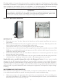
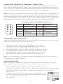
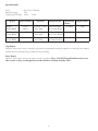
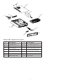
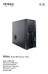
MINUET 300
User’s Manual
1
TABLE OF CONTENTS
Minuet 300 ...................................................... 2
Setting Up ........................................................ 2
Motherborad Installation .................................. 2
Power/LED Connections .................................. 3
Connecting The USB Ports .............................. 3
Connecting The IEEE 1394
(FireWire®, i.Link®) Port ................................... 4
Connecting The Audio Ports ............................ 4
Drive Installation ............................................. 4
Cooling System ................................................ 5
Specifications ................................................... 6
Explorer Description ........................................ 7
1
The high quality of our products is assured by a continuous process of refinement of their technical features. Therefore, it is possible that your product may differ in some respect from the descriptions contained in this manual. This is not a problem– it is an improvement. All features, descriptions and illustrations contained herein are valid as of the date of publication.
Disclaimer
This manual is intended only as a guide for Antec’s Computer Enclosures. For more
comprehensive instructions on installing your motherboard and peripherals, please refer
to the user’s manuals, which come with your components and drives.
MINUET 300 USER’S MANUAL
SETTING UP
1. Take the case out of the box. Remove the Styrofoam and the plastic bag. Place the case on a
flat surface.
2. Remove the thumbscrews from the top panel (at the rear of the case). Slide the panel to the
rear of the case and remove it. Set the panel safely aside.
Note: Please don’t try to use your fingernails to pry or lift the panel.
3. Inside the case you should see the power supply, some wiring with marked connectors (USB,
PWR etc.), an installed I/O panel and a power cord. You will also find a bag of screws, four
rubber feet and two plastic stands.
4. Horizontal Orientation: stick the four adhesive rubber feet to the bottom panel of the case to
protect the paint from scratches.
5. Vertical Orientation: place the Minuet in the two plastic stands such that the side panel with
the 80mm fan is facing up. Adjust the stands to fit snugly against the case sides.
[Applicable only to models designed for sale in the European Union: All Antec power supplies
designed for the EU include a Power Factor Correction (PFC) circuitry in accord with European
standard regulation code EN61000-3-2. By altering the input current wave shape, PFC improves
the power factor of the power supply and results in increased energy efficiency, reduced heat loss,
prolonged life for power distribution and consumption equipment, and improved output voltage
stability.]
MOTHERBOARD INSTALLATION
This manual is not designed to cover CPU, RAM, or expansion card installation. Please consult
your motherboard manual for specific mounting instructions and troubleshooting.
1.
Make sure you have the appropriate I/O panel for your motherboard. If the standard panel
provided with Minuet is not suitable for your motherboard,please contact your motherboard
manufacturer for the correct I/O panel.
2
2.
3.
4.
5.
6.
Line up your motherboard with the standoff holes, and determine which ones line up and
remember where they are. Not all motherboards will match with all of the provided screw
holes, and this is not necessary for proper functionality. (In other words there will likely be
extra holes.) Some standoffs may be pre-installed for your convenience.
Lift up and remove your motherboard.
Screw in the brass standoffs to the threaded holes that line up with your motherboard’s
mounting holes.
Place your motherboard on the brass standoffs.
Mount your motherboard on the standoffs with the provided Phillips-head screws. Your motherboard is now installed.
POWER/LED CONNECTIONS
The power supply is an ATX12V form factor power supply. It has a single 24-pin Main Power
Connector, and a 4-pin +12V Power Connector for the motherboard. It is backwards compatible to
previous ATX form factor power supplies. If your motherboard does not support the +12V 4-pin
Power Connector, you can still use this power supply. It also comes with three 4-pin Peripheral
Power Connectors, one SATA Power Connector and one 4-pin Floppy Drive Power Connector for
your drives.
1.
2.
3.
4.
Connect the 24-pin ATX power connector (and +12V connectors if appropriate) to your
motherboard. If your motherboard uses a 20-pin connector; detach the 4-pin attachment on
24-pin power connector (see picture 1 and 2).
Power LED (labeled POWER LED) connector is located behind
the Reset connector.
Power Switch (labeled POWER SW) connects to the PWR
connector on the motherboard.
Hard Drive LED (labeled H.D.D. LED) connects to the IDE
connector.
CONNECTING THE USB PORTS
You will find a single 10-pin connector on a cable attached to the front USB ports. This is an Intel
standard connector which is keyed so that it can’t be accidentally reversed as long as it is connected
to a proper Intel standard motherboard header. Connect the 10-pin connector to your motherboard
headers so that the blocked pin fits over the missing header pin.
Note: Please check your motherboard manual for your USB header pin layout and make sure it
matches the attached table. If it does not match this Intel standard, please call Antec customer
support at (800) 22ANTEC (North America) or at +31 (0) 10 462-2060 (Europe) to buy a USB
adapter. This adapter will allow you to connect the front USB to your motherboard on a pin-by-pin
basis.
Intel Standard USB Header Pin Layout
1
9
2
10
Pin
Signal Names
Pin
Signal Names
1
USB Power 1
2
USB Power 2
3
Negative Signal 1
4
Negative Signal 2
5
Positive Signal 1
6
Positive Signal 2
7
Ground 1
8
Ground 2
9
Key (No Connection)
10
Empty Pin
3
®
®
CONNECTING THE IEEE 1394 (FIREWIRE , I.LINK ) PORT
You will find a single 10-pin connector on a cable attached to the front IEEE 1394 connection.
This is an Intel standard connector, which is keyed so that it can’t be accidentally reversed as long
as it is connected to a proper Intel standard motherboard header. Connect the 10-pin connector to
your motherboard header so that the blocked pin fits over the missing header pin.
Note: Please check your motherboard manual for your IEEE 1394 header pin layout and make sure
it matches the attached table. If you intend to connect the front FireWire port to an IEEE 1394
add-on card that comes with an external-type IEEE1394 connector, please call Antec customer service at (800) 22ANTEC (North America) or +31 (0) 10 462-2060 (Europe) to buy an adapter. This
adapter will allow you to connect the front IEEE 1394 port to the external-type connector.
Standard Pin Assignment for IEEE 1394 Connector
1
9
2
10
Pin
Signal Names
Pin
Signal Names
1
TPA +
2
TPA -
3
Ground
4
Ground
5
TPB +
6
TPB -
7
+12V (Fused)
8
+12V (Fused)
9
Key (No pin)
10
Ground
CONNECTING THE AUDIO PORTS
Locate the internal audio connectors from your motherboard or sound card. Consult your motherboard or sound card manual for the pin-out positions.
1.
2.
3.
4.
5.
6.
7.
Microphone Signal Pin: Connect the MIC-IN connector to this pin.
Microphone Power: Connect the MIC-POWER connector to this pin.
Ground Pin: Connect the GROUND connector to this pin.
Front Right Speaker Out Pin: Connect the R-OUT connector to this pin.
Front Right Speaker Out Pin: Connect the L-OUT connector to this pin.
Rear Right Speaker Out Pin: Connect the R-RET connector to this pin.
Rear Left Speaker Out Pin: Connect L-RET connector to this pin.
Note: If your motherboard is not equipped with REAR SPEAKER output, it is not necessary to
use the R-RET and L-RET connectors.
DRIVE INSTALLATION
Minuet incorporates a rapid-release Flip Up Drive Cage for easy drive installation. The Cage includes three drive bays: one external 5.25”, one external 3.5”, and one internal 3.5”.
1.
a.
Before installing the external drives, remove the external drive bay covers.
To remove the external 5.25” drive bay cover, face the front of the case and use your left hand
thumb to press firmly on the LEFT or outside edge of the left bay cover to release it.
(See picture 3)
b. To remove the external 3.5” drive bay cover, face the front of the case
and use your right hand thumb to press firmly on the RIGHT or outside
edge of the right bay cover to release it.
(See picture 4)
4
2.
3.
4.
Lift up and slide the drive cage from the case.
Place the cage upside down on a flat surface.
Note: You must install the external devices first, before installing the
internal 3.5” device.
5. Slide the external 5.25” device into the drive cage from the front.
Since the drive cage is upside down, your drive should be too so that it
will be properly orientated once the cage is installed in the Minuet II.
6. Align the bottom rear screw holes (one at each side) on the device
with the two screw holes (the pair closest to the front of the cage) on
the cage and fasten the device with the screws provided.
(See picture 5)
7. Slide the external 3.5” device into the drive cage from the front. Since
the drive cage is upside down, your drive should be too so that it will
be properly orientated once the cage is installed in the Minuet II.
8. Align the bottom rear screw holes (one at each side) on the device
with the two screw holes on the cage and fasten the device with the
screws provided. (See picture)
9. To install the internal 3.5” device, find the two mounting prongs on
one side of the bay. With one hand holding the device at a 45-degree
angle with the bottom side up, align the two screw holes on
one side of the device with the prongs and slide the device into the
bay. (See picture 7)
10. Fasten the other side of the device to the two tabs with the screws
provided. (See picture 8.)
11. When sliding the Cage back into the case, work slowly and carefully to
ensure that the front panels of the external devices align properly with
the holes provided for them in the bezel.
12. Connect power to each of the devices.
COOLING SYSTEM
The TriCool fan
The case includes one 80mm TriCool fan installed in the side of the chassis.
This fan has a three-speed switch that lets you choose between quiet, performance, or maximum cooling. We set the default fan speed to “Medium”. (See specifications below)
The fan is installed so that the air is blowing out of the case. Connect a large 4-pin connector from
the power supply to the male 4-pin connector on the fan. Note: The minimum voltage to start
the fan is 5V. We recommend our users to set the fan speed to High if you choose to connect the
fan to a fan control. A fan control device regulates the fan speed by varying the voltage to it. The
voltage may start as low as 4.5V to 5V. Connecting a TriCool set on Medium or Low to a fan-control device may result in the fan not being able to start. The already lowered voltage from the fan
control device will be further reduced by the TriCool circuitry below 5V.
5
Specifications:
Size:
80 x 80 x 25.4mm
Rated Voltage:
12V
Operating Voltage: 10.2V ~ 13.8V
Speed
Input Current
High
2600 RPM
0.2A
(Max.)
Medium
2000 RPM
Low
1500 RPM
Air Flow
Static Pressure
Acoustical
Noise
Input Power
0.96 m³ / min 3.04 mm-H2O
(34 CFM)
(0.12 inch-H2O)
30 dBA
2.4W
0.15A
0.74 m³ / min 1.79 mm-H2O
(26 CFM)
(0.07 inch-H2O)
24 dBA
1.8W
0.1A
0.55 m³ / min 1.00 mm-H2O
(20 CFM)
(0.03inch-H2O)
18 dBA
1.2W
Top Panel:
Minuet 300 comes with a vented top panel for maximum cooling capacity. It will help the airflow
inside the case maximizing ventilation and cooling.
Rear Panel:
Minuet 300 comes with vents above the I/O panel. Note: Do NOT install exhausts fans over
these vents as they are designed to intake fresh air to help cool the CPU.
6
1
2
3
4
14
13
12
5
7
6
8
11
9
Minuet 300 - Explorer Description
#
Description
#
Description
1
Thumbscrews
8
3.5” Drive Bay Cover
2
Top Panel with Vent
9
Front Bezel
3
Power Supply
10
5.25” Drive Bay Cover
4
Flip Up Drive Cage
11
Front PCB Assembly
5
Power Switch/Cable
12
Case
6
Power LED/Cable
13
Expansion Slot Covers
7
HD LED/Cable
14
I/O Panel
7
Antec, Inc.
47900 Fremont Blvd.
Fremont, CA 94538
tel: 510-770-1200
fax: 510-770-1288
Antec Europe B.V.
Sydneystraat 33
3047 BP Rotterdam
The Netherlands
tel: +31 (0) 10 462-2060
fax: +31 (0) 10 437-1752
Customer Support:
US & Canada
1-800-22ANTEC
[email protected]
Europe
+31 (0) 10 462-2060
[email protected]
www.antec.com
Antec Quality 3-Year parts and labor warranty (A3Q)
See details at: http://www.antec.com/warranty.php
© Copyright 2005Antec, Inc. All rights reserved. All trademarks are the property of their respective owners.
Reproduction in whole or in part without written permission is prohibited.Printed in China.
Version 1.0.1 01/01/2006
8