1
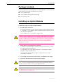
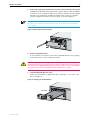
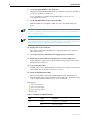
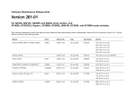
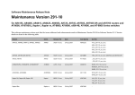
Uplink Module
Quick Install Guide
AT-A35/SX
AT-A35/LX
AT-A39/T
AT-A40/SC
AT-A40/MT
AT-A41/SC
AT-A41/MT
AT-A42/GBIC
Uplink Module Quick Install Guide
Document Number C613-04022-01 REV G.
Copyright © 1999-2005 Allied Telesyn International, Corp.
19800 North Creek Parkway, Suite 200, Bothell, WA 98011, USA.
All rights reserved. No part of this publication may be reproduced without prior written
permission from Allied Telesyn.
Allied Telesyn International, Corp. reserves the right to make changes in specifications
and other information contained in this document without prior written notice. The
information provided herein is subject to change without notice. In no event shall Allied
Telesyn be liable for any incidental, special, indirect, or consequential damages
whatsoever, including but not limited to lost profits, arising out of or related to this
manual or the information contained herein, even if Allied Telesyn has been advised of,
known, or should have known, the possibility of such damages.
All trademarks are the property of their respective owners.
Quick Install Guide
3
Models Covered By This Guide
‘This Quick Install Guide includes information on the following models:
■
AT-A35/SX
■
AT-A35/LX
■
AT-A39/T
■
AT-A40/SC
■
AT-A40/MT
■
AT-A41/SC
■
AT-A41/MT
■
AT-A42/GBIC
Quick Install Guide updates can be found at www.alliedtelesyn.co.nz/
support/support.html.
Compatible Switch Units
This section lists all uplink module models, and indicates which switches each
model can be installed in.
C613-04022-01 REV G
•
AT-A35/SX: All Rapier Switches, Rapier i switches, AT-8700XL
switches and AR800 Modular Switching Routers
•
AT-A35/LX: All Rapier Switches, Rapier i switches, AT-8700XL
switches and AR800 Modular Switching Routers
•
AT-A39/T: All Rapier Switches, Rapier i switches, AT-8700XL switches
and AR800 Modular Switching Routers
•
AT-A40/SC: Rapier G6 and G6F switches and all Rapier i and
AT-8700XL switches
•
AT-A40/MT: Rapier G6 and G6F switches and all Rapier i and
AT-8700XL switches
•
AT-A41/SC: Rapier G6 and G6F switches and all Rapier i and
AT-8700XL switches
•
AT-A41/MT: Rapier G6 and G6F switches and all Rapier i and
AT-8700XL switches
•
AT-A42/GBIC: All Rapier Switches, Rapier i switches, AT-8700XL
switches and AR800 Modular Switching Routers
4
Uplink Module
Package Contents
The following items are included with each Uplink Module. Contact your sales
representative if any items are damaged or missing.
■
One Uplink Module.
■
One Uplink Module Quick Install Guide.
■
One warranty card.
Installing an Uplink Module
Follow these steps to install an uplink module:
1.
Read the safety information
For safety information, see the Safety and Statutory Information booklet for
your switch. A copy of this booklet is supplied with each switch, and can
also be downloaded from
www.alliedtelesyn.co.nz/support/support.html.
AT-82xx Expansion Modules are not compatible with AR800 Series Modular
Switching Routers, Rapier, Rapier i or AT-8700XL Switches. Attempting to
install an AT-82xx Expansion Module into one of these switches may damage
the switch unit and Expansion Module. If you are unsure of a Module’s
compatibility, before installing it, contact an authorised Allied Telesyn
distributor or reseller.
2.
Gather the tools and equipment you will need
A medium-sized flat-bladed screwdriver may be useful when loosening
the Uplink Module thumbscrews.
You should also have any cables required for connecting the Uplink
Module to other network devices.
AT-A42/GBIC uplink modules require a GBIC before they can be
connected to a network.
3.
If connected, disconnect the switch unit from its redundant power supply
4.
Disconnect the switch unit from the main power supply
Be sure to disconnect the power cord and the redundant power supply cable
before installing an Uplink Module. Installing an Uplink Module with the
switch unit powered ON can damage the Uplink Module.
The power cord and the redundant power supply cable are used to disconnect
AC switch units. To de-energise the equipment, disconnect the power cord and
the redundant power supply cable.
C613-04022-01 REV G
Quick Install Guide
5
5.
Remove the appropriate uplink bay face-plate on the switch unit’s front panel
AR800 Series Modular Switching Routers, Rapier, Rapier i and AT-8700XL
Switches have two uplink module expansion bays. If this is the first Uplink
Module to be installed, it should be installed in the top bay (to simplify
VLAN configuration). Remove the face-plate as shown in Figure 1.
Keep the face-plate for future use. If you should remove the Uplink Module, replace the
face-plate to prevent dust and debris from entering the switch unit and to maintain
proper airflow.
Figure 1: Removing a blank face-plate.
A
B
6.
Prepare the Uplink Module
In an antistatic environment, remove the Uplink Module from its packing
material. Be sure to observe ESD precautions.
Do not attempt to install an Uplink Module or any other expansion option
without observing correct antistatic procedures. Failure to do so may damage
the switch unit or Uplink Module. If you are unsure what the correct procedures
are, contact your authorised Allied Telesyn distributor or reseller.
7.
Slide the Uplink Module into place
Make sure the module is aligned with the card guides on each side of the
bay (see Figure 2).
Figure 2: Installing an Uplink Module.
Card Guide
A
ACTIVITY
AT-A35/S
X
TX
LINK
RX
ACTIVITY
B
FULL DUP
HALF DUP
LINK
COL
COL
1000BAS
E-FX/SC
FULL DUP
COL
HALF DUP
C613-04022-01 REV G
6
Uplink Module
8.
Secure the Uplink Module to the switch unit
Firmly press the Uplink Module until its connectors engage the uplink bay
connectors inside the switch unit.
Use a screwdriver to tighten the Uplink Module’s screws. Do not
over-tighten the screws.
9.
For AT-A42/GBIC uplink modules, install the GBIC
Slide the GBIC into the uplink’s GBIC slot. Press the GBIC firmly into
place.
A range of GBICs have been tested and approved for use with AT-A42 uplink modules.
Contact your authorised Allied Telesyn distributor or reseller for more information, or
visit www.alliedtelesyn.co.nz.
RX and TX terminal locations on SC fibre GBIC ports are the reverse of TX and RX
terminal locations on fixed SC fibre ports. When looking at an SC fibre GBIC from the
front, the RX terminal is on the left and the TX terminal is on the right.
10. Apply power to the switch unit
The switch’s Fault LED should flash for approximately 10 seconds as it
runs internal tests.
11. If you disconnected a redundant power supply in step 3, reconnect it
12. Check that the Power LED on the switch unit’s front panel lights green
If the LED fails to light, refer to the Troubleshooting section of the Uplink
Module Hardware Reference.
13. Connect the data cables
If fitted, remove the Uplink Module’s port dust cover, and connect the data
cable. Make sure each cable connection is secure.
14. Check the Uplink Module’s LEDs
The following tables outline the Uplink Module LEDs. Information on
Switch System and Switch Port LEDs can be found in the Troubleshooting
section of the Hardware Reference for your switch unit.
LED legend
LED is On and Green
LED is Flashing Green
LED is On and Amber
LED is Flashing Amber
LED is Off.
Table 1: AT-A35/SX and AT-A35/LX LEDs.
LED
State
Function
Link
Green
The port is receiving light
Off
No link is present
C613-04022-01 REV G
Quick Install Guide
7
Table 1: AT-A35/SX and AT-A35/LX LEDs.
LED
State
Function
Activity
Flashing Amber
Frames are being transmitted or received
through the port
Off
No activity is occurring
Table 2: AT-A39/T LEDs.
LED
State
Function
Full Dup/Half
Dup/Col
Green
The port is operating at full-duplex
Amber
The port is operating at half-duplex
Flashing amber
Collisions are occurring
Off
No link is present
Green
A 1000 Mbps link is open
Flashing green
1000 Mbps activity is occurring
Amber1
A 10/100 Mbps link is open
Flashing Amber1
10/100 Mbps activity is occurring
Off
No link is present
Activity
1. 10/100/1000 Mbps operation is available only if the AT-A39/T Uplink Module is installed in a Rapier
G6, Rapier G6F, Rapier i or AT-8700XL model, otherwise operation is fixed at 1000 Mbps. Early
versions of the AT-A39/T operate at 1000 Mbps only, regardless of the switch model.
Table: 3 AT-A40/SC, AT-A40/MT, AT-A41/SC and AT-A41/MT LEDs1.
LED
State
Function
Activity/Link/Fault
Green
A link is open and the port is enabled
Flashing green
100 Mbps activity is occurring
Flashing amber
(and lower LED is Off)
The link has failed at the remote end
Off
No link is present
Green
The port is operating at full-duplex
Amber
The port is operating at half-duplex
Flashing amber
Collisions are occurring
Off
No link is present
Alternate flashing of
upper and lower LED,
amber
The switch does not support this model
of uplink module
Full Dup/Half
Dup/Col
Both LEDs
1. AT-A40 and AT-A41 Uplink Modules can only be installed in Rapier G6, G6F, Rapier i and
AT-8700XL switches.
C613-04022-01 REV G
8
Uplink Module
Table: 4 AT-A42/GBIC LEDs .
LED
State
Function
L/A
Green
A 1000 Mbps link is open
Flashing green
1000 Mbps activity is occurring
Flashing amber
(and GBIC LED is Off)
A TX fault has occurred
Off
No link is present
Green
The switch has recognised the GBIC,
the GBIC is a valid model
Green
(and L/A LED is flashing
GREEN)
The port is operating at full-duplex
Amber
(and L/A LED is OFF)
The switch has not recognised the
GBIC, the GBIC is not a valid model
Amber
(and L/A LED is flashing
GREEN)
The port is operating at half-duplex
Flashing amber
(and L/A LED is flashing
GREEN)
Collisions are occurring
Off
No GBIC is installed, or a TX fault has
occurred
Slow alternate flashing of
L/A and GBIC LED, amber
The switch has not recognised the
GBIC, or the GBIC is not a valid model
Link/Activity
GBIC
Both LEDs
Where To Find More Information
Sources of further information.
Information on Uplink Modules:
■
The Uplink Module Hardware Reference, which provides detailed
information on Uplink Modules.
Information on Switches and Switching Routers:
■
The Hardware Reference for your switch or switching router, which provides
detailed information on the switch unit and its hardware features.
■
The Software Reference for your switch or switching router, which provides
detailed information on configuring the switch unit and its software.
■
The User Guide for your switch or switching router, which provides an
introduction to the switch unit’s Graphical User Interface and its Layer 2
switching features.
C613-04022-01 REV G
Quick Install Guide
9
Information on other expansion options for the AR800, Rapier, Rapier i and
AT-8700XL Series:
■
The Network Service Module Quick Install Guide, which outlines the
procedure for installing an NSM; and the Network Service Module Hardware
Reference, which provides detailed information on NSMs.
■
The Port Interface Card Quick Install Guide, which outlines the procedure for
installing PICs; and the Port Interface Card Hardware Reference, which
provides detailed information on PICs.
All of these documents can be found on the Documentation and Tools CDROM bundled with each Switch or Switching Router, or at
www.alliedtelesyn.co.nz/support/support.html.
C613-04022-01 REV G