1
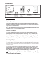
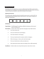
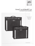
Public View
CE-20DVRPVM-HD &
CE-8DVRPVM-HD
User Manual
CLINTON Electronics
6701 Clinton Road
Loves Park, IL 61111
POWER
AUTO
1.800.447.3306 Sales
1.800.549.6396 Support
1.800.633.8712 Fax
UP
DOWN
www.clintonelectronics.com
MENU
v.02.16.10
Table of Contents
Introduction . . . . . . . . . . . . . . . . . . . . . . . . . . . . . . . . . . . . . . . . . . . . . . . . . . . . . . . . . . . . . . . . . . . 3
Display
Contents, Installation and Set-up . . . . . . . . . . . . . . . . . . . . . . . . . . . . . . . . . . . . . . . . . . . . . . . 4
Adjusting the Display. . . . . . . . . . . . . . . . . . . . . . . . . . . . . . . . . . . . . . . . . . . . . . . . . . . . . . . . . . . 5
Feature List . . . . . . . . . . . . . . . . . . . . . . . . . . . . . . . . . . . . . . . . . . . . . . . . . . . . . . . . . . . . . . . . . . . . 6
Remote Control . . . . . . . . . . . . . . . . . . . . . . . . . . . . . . . . . . . . . . . . . . . . . . . . . . . . . . . . . . . . . . . . 7
Display Set-up . . . . . . . . . . . . . . . . . . . . . . . . . . . . . . . . . . . . . . . . . . . . . . . . . . . . . . . . . . . . . . . 8-9
PIR Controls . . . . . . . . . . . . . . . . . . . . . . . . . . . . . . . . . . . . . . . . . . . . . . . . . . . . . . . . . . . . . . . . . . . 10
Access to Camera and OSD Board . . . . . . . . . . . . . . . . . . . . . . . . . . . . . . . . . . . . . . . . . . . . . . 11
.
Settings . . . . . . . . . . . . . . . . . . . . . . . . . . . . . . . . . . . . . . . . . . . . . . . . . . . . . . . . . . . . . . . . . . . . . . .12
Lens, Shutter . . . . . . . . . . . . . . . . . . . . . . . . . . . . . . . . . . . . . . . . . . . . . . . . . . . . . . . . . . . . . . . . . . 13
White Balance . . . . . . . . . . . . . . . . . . . . . . . . . . . . . . . . . . . . . . . . . . . . . . . . . . . . . . . . . . . . . . . . .14
Backlight, AGC (Auto Gain Control) . . . . . . . . . . . . . . . . . . . . . . . . . . . . . . . . . . . . . . . . . . . . 15
DNR (Digital Noise Reduction), SENS UP. . . . . . . . . . . . . . . . . . . . . . . . . . . . . . . . . . . . . . . . .16
Special Function. . . . . . . . . . . . . . . . . . . . . . . . . . . . . . . . . . . . . . . . . . . . . . . . . . . . . . . . . . . .17-20
DVR
DVR Controls / Settings . . . . . . . . . . . . . . . . . . . . . . . . . . . . . . . . . . . . . . . . . . . . . . . . . . . . . . . . 21
Playback . . . . . . . . . . . . . . . . . . . . . . . . . . . . . . . . . . . . . . . . . . . . . . . . . . . . . . . . . . . . . . . . . . . . . . 22
Menu, Date & Time . . . . . . . . . . . . . . . . . . . . . . . . . . . . . . . . . . . . . . . . . . . . . . . . . . . . . . . . . . . . 23
Motion Setup . . . . . . . . . . . . . . . . . . . . . . . . . . . . . . . . . . . . . . . . . . . . . . . . . . . . . . . . . . . . . . . . . 24
Manual Record, Schedule Record . . . . . . . . . . . . . . . . . . . . . . . . . . . . . . . . . . . . . . . . . . . . . . 25
Schedule Setup, Alarm, Record, Motion Record . . . . . . . . . . . . . . . . . . . . . . . . . . . . . . . . 26
Continue Record, SD Card Options . . . . . . . . . . . . . . . . . . . . . . . . . . . . . . . . . . . . . . . . . . . . . 27
System Status, Power-On Setup, Factory Default . . . . . . . . . . . . . . . . . . . . . . . . . . . . . . . 28
Troubleshooting . . . . . . . . . . . . . . . . . . . . . . . . . . . . . . . . . . . . . . . . . . . . . . . . . . . . . . . . . . . . . . 29
2
Introduction
Congratulations on the purchase of your new Public View Integrated Camera Security
display. This display and camera combination is designed for simple and effective loss
prevention by making the viewer aware of video surveillance measures. The BNC output
allows the video to be recorded on a DVR or VCR device.
Features:
• Rugged Steel Enclosure
• Low Voltage power supply
• Integrated High-Resolution Digital Day & Night Camera (540 TVL)
• VESA mounting pattern for ceiling or wall mount options
• Remote control operation of all screen adjustment features
• Wide viewing angles
Precautions
• There are no user serviceable parts inside the unit. Authorized service personnel must perform all service. To avoid electrical shock, do not disassemble the unit. Any attempt to disassemble the unit will void the warranty.
• Verify DC power supply before installation. This unit requires an external AC to DC power supply capable of supplying sufficient DC voltage to the display.
• Install the monitor in a location that is suitable for the display. Make sure there is adequate ventilation around the unit, and that the display is mounted securely to it’s support structure.
• Do not place the monitor in direct sunlight, or near sources of heat.
• Do not place the monitor in a damp area.
• Do not place the monitor in an area that is below 40˚F.
• Clean the monitor with water or non-ammonia glass cleaners only. Do not use abrasive cleaners, abrasives, or highly concentrated ammonia to clean the front
of the display. Clean with a damp cloth only, do not spray directly with water.
3
PACKAGE CONTENTS
POWER
POWER
UP
AUTO
DOWN
MENU
POWER
AUTO
UP
DOWN
AUTO
UP
DOWN
MENU
MENU
2
GB
SD Card
2
16
GB
SD Card
AUTO
UP
DOWN
2
GB
SD Card
2 SDHC Cards
• DVR (16GB)
• Video (2GB)
CE-DVRPVM
POWER
GB
SD Card
MENU
16
16
GB
SD Card
GB
SD Card
Remote Controls
• DVR
• Display
Power Pigtail
(for Hardwiring)
User Manual
Installation and Set up
Unpacking your display
2
GB
16
GB
Your Public View display comes with the remote control and power connector. Carefully
remove the display from it’s packing and set the unit on a firm surface. Save the packing in
case of future service requirements.
SD Card
SD Card
NOTE: Any shipment of the display must have the protective plastic cover taped to the
front of the display to prevent shipping damage.
Installation of the display
The display should be located where it will have the most effect on deterring potential
shoplifting. Keep in mind the lighting conditions, viewing area, ease of installation, and
distance from the power supply when choosing a location. The display is compatible with
many available wall and ceiling mounts, consult your dealer for suggestions. The rear of the
display has a VESA 100mm mounting pattern that accepts M4 screws. Please refer to the
installation instructions on the particular mounting bracket and details of how to install.
Connecting the display
This display requires a 24V DC power supply. Locate the applicable AC to DC power supply
in a suitable location where there is an AC power source, and access to run the low voltage
cable to the display.
For single unit power supplies, you will need to keep the distance from the power supply
to the display less than 25 ft. For multiple unit power supplies, the power supply can be
located at further distances from the displays at a central location. Please refer to the specific
power supply installation instructions for recommended wire size and distances.
Caution: Do not connect the power connector to the display when energized,
doing so may damage the electronics inside the display. Connect power supply
to unit, then to 120v wall outlet.
4
Adjusting the Display
The display comes from the factory in a pre-set configuration that will be very close to the
final set up for most installations. Minor adjustments can be made to the monitor and camera
to optimize the picture quality for a particular installation when required.
Adjusting the monitor
The monitor can be adjusted by either the included remote control, or with the OSD (On
Screen Display) buttons located at the rear of the monitor. These controls will adjust all
parameters of the display.
POWER
AUTO
UP
DOWN
MENU
OSD Buttons
Power Button – On/Off function. This will power off both the display and the internal
camera simultaneously.
Menu Button – To adjust audio, video, signal, tools, language use up & down buttons.
a.
Push menu button once.
b.
Push up or down button to pick category.
c.
Push menu button for sub-category.
d.
Push up or down button for movement within sub-category.
e.
When sub-category is chosen, push menu button again.
f. Push up or down button to make your adjustment.
g. After adjustment has been made, menu display will turn off automatically.
2
16
Auto Button – Switches video source. Steps back to previous screen when in menu.
GB
SD Card
5
SD Card
GB
Features
CE-20DVRPVM-HD
Dwell Time Dial
Sensor Switch
Sensitivity Dial
Audio Switch
Camera
PIR
Sensor
LED
Flasher
SD Card
Inserted
Light (behind glass)
Video SD
card slot
OSD menu
buttons
DVR SD
card slot
Power
Supply
Input
BNC Output
OSD
VGA Input
Board
Controls
(bottom)
CE-8DVRPVM-HD
OSD menu buttons
Power Indicator Light
BNC Output
Audio Switch
Sensitivity Dial
Sensor Switch
Dwell Time Dial
Power Supply Input
IR Sensor
SD Card
Inserted
Light
Camera
PIR
Sensor
LED
Flasher
Video SD
card slot
6
OSD Board
Camera Controls
DVR SD
card slot
Remote Control
Power
Selection Arrows
Menu
Sleep
TV (source)
Display Remote
Power – On/Off function. This will power off both the display and the internal camera.
Menu – To adjust audio, video, signal, tools, language use up & down buttons.
• Push MENU button once.
• Use arrow buttons located around the MENU button to pick category.
• When correct category is chosen, press VOL- and VOL+ buttons to adjust given parameter of display.
• When adjustment of selected parameter is done, press MENU again to go back to the previous screen, or simply wait for the menu screen to time out.
Sleep (ZZZ) –Used to set a sleep timer from 10-90 minutes. This will turn the display off after the
programmed amount of time. Continue pressing the sleep button to select the desired time, or
to turn the function off.
TV (source) –Switches video sources. (use to enter DVR menu).
7
Display Set-up
Video Menu: The display should be pre-set for most installations, however if some adjustment
is necessary, we suggest you follow these recommendations by pressing the MENU button on
the Display remote:
1. First adjust the BRIGHTNESS control to set the black level so that the images are at their brightest while the black images are still black. Do not adjust too high where the black portions of the image become gray or the image will have a “washed out” appearance.
2. Set the CONTRAST control to set the white level so that the images are at their brightest without losing definition in the white portions of the image.
3. Adjust the COLOR control to achieve a realistic image of the items within the viewing area.
4. Adjust the TINT control if the image has bluish or reddish tint to the white portions of the image.
5. Adjust the SHARPNESS lower if the image appears too grainy or pixelated. Increase the SHARPNESS if the image appears too soft. Note: Adjust the SHARPNESS control only after adjusting the camera lens for optimum focus.
6. The RESET selection can be used to return the Video settings back to the factory defaults.
8
Audio Menu
1. The Audio Menu will not be used on this unit. It has no impact on the volume of the motion chime that is set on the back of the unit. The MUTE function on the remote also has no impact on the motion chime.
Feature Controls Menu
1. The SLEEP TIMER is adjustable from 0min to 90min. After which time, the display will time out until motion
2. The LANGUAGE can be changed to one of the following: English, French, German, Spanish, Italian, Dutch, Greek, Swedish.
3. In the OSD CONTROL menu you can set the horizontal and vertical position of the OSD menu, as well as rotate or mirror the menu., and control the duration the menu is on screen 2-16 seconds.
4. The LED light on the front of the unit can be turned on or off using the LED CONTROL function.
5. In the MESSAGE CONTROL setting, you can turn the message on the bottom of the screen on or off, as well as select the message to read “WELCOME” or “RECORDING IN PROGRESS”. You can also control the message to flash on and off, or be steady on.
* 6. Pressing the left (VOL -), or right (VOL +) buttons under the FACTORY RECALL selection will return all display settings back to the factory defaults. Doing so will void all of your custom settings.
9
ide for CE-20DVRPVM-HD & CE-8DVRPVM-HD
PIR SENSOR CONTROLS
PSZUPSFDPSEPONPUJPO5IFTFTFUUJOHTIBWFCFFOQSFMPBEFEBOETIPVMEOPUCFDIBOHFE
PIR Sensor Controls
UJOHUIF4%DBSETFUUJOHUIFMPDBMUJNFBOEJGEBZMJHIUTBWJOHTUJNF%45
JTSFDPHOJ[FEJOZPVSBSFB
5IF1*3TFOTPSQJOIPMFMPDBUFEGSPOUDFOUFSPOVOJU
DPOUSPMTUIFTDSFFO
TXJUDIJOHPGUIFøBTIDBSEQMBZFSUPUIFCVJMUJODBNFSB*UBMTPDPOUSPMT
UIFBVEJP#FTVSFUPLFFQUIFTNBMMIPMFPQFOBUBMMUJNFTBOEGSFFPGEVTU
*UEPFTOPUDPOUSPMUIF%73NPUJPOSFDPSEJOHUIF3&$03%*/(*/130(3&44
UFYUPOUIFTDSFFOPSUIFGSPOU-&%
1. CHANGE
DURATION
OF CAMERA IMAGE ON SCREEN
PIRTHE
SENSOR
CONTROLS
t*ODSFBTFUVSODMPDLXJTF
UIFi%XFMM5JNFwEJBMUPBMMPXUIF
TFUUJOHT
5IF1*3TFOTPSQJOIPMFMPDBUFEGSPOUDFOUFSPOVOJU
DPOUSPMTUIFTDSFFO
-$%UPEJTQMBZUIFDBNFSBJNBHFMPOHFSPOUIFTDSFFO
TXJUDIJOHPGUIFøBTIDBSEQMBZFSUPUIFCVJMUJODBNFSB*UBMTPDPOUSPMT
t%FDSFBTFUVSODPVOUFSDMPDLXJTF
UIFi%XFMM5JNFwEJBMUP
UIFBVEJP#FTVSFUPLFFQUIFTNBMMIPMFPQFOBUBMMUJNFTBOEGSFFPGEVTU
BMMPXUIF-$%UPEJTQMBZUPDZDMFCBDLUPUIFQSFMPBEFE+1&(JNBHF
*UEPFTOPUDPOUSPMUIF%73NPUJPOSFDPSEJOHUIF3&$03%*/(*/130(3&44
POUIF4%$BSENPSFGSFRVFOUMZ
FOV
UFYUPOUIFTDSFFOPSUIFGSPOU-&%
2. TURN OFF THE STATIC JPEG- SD CARD IMAGE
1. CHANGE THE DURATION OF CAMERA IMAGE ON SCREEN
4XJUDIJOHUIFi4FOTPSwTXJUDIUPi0''wEJTBCMFTUIF1*34FOTPSXIJDI
EJTBCMFTUIF+1&(JNBHFGSPNBQQFBSJOHPOUIFTDSFFO
t*ODSFBTFUVSODMPDLXJTF
UIFi%XFMM5JNFwEJBMUPBMMPXUIF
OFXTFUUJOHT
-$%UPEJTQMBZUIFDBNFSBJNBHFMPOHFSPOUIFTDSFFO
3. CHANGE
THE SENSITIVITY OF THE MOTION SENSOR
t%FDSFBTFUVSODPVOUFSDMPDLXJTF
UIFi%XFMM5JNFwEJBMUP
OLID
BMMPXUIF-$%UPEJTQMBZUPDZDMFCBDLUPUIFQSFMPBEFE+1&(JNBHF
t5VSOJOHUIFi4FOTJUJWJUZwEJBMDMPDLXJTF*ODSFBTFTUIFTFOTJUJWJUZ
POUIF4%$BSENPSFGSFRVFOUMZ
t5VSOJOHUIFi4FOTJUJWJUZwEJBMDPVOUFSDMPDLXJTF%FDSFBTFTUIFTFOTJUJWJUZ
OV
NFTTBHF
SPMw
FUUJOHT
4. TURN
OFF THE
AUDIO
2. TURN
OFFMOTION
THE STATIC
JPEG- SD CARD IMAGE
4XJUDIJOHUIFi4FOTPSwTXJUDIUPi0''wEJTBCMFTUIF1*34FOTPSXIJDI
4XJUDIJOHUIFi$IJNFwTXJUDIUPi0''wEJTBCMFTUIFBVEJPUIBUJT
EJTBCMFTUIF+1&(JNBHFGSPNBQQFBSJOHPOUIFTDSFFO
JOJUJBUFECZUIFNPUJPOTFOTPS
%XFMMUJNF
_
+
0/
4FOTPS
0''
%XFMMUJNF
4FOTJUJWJUZ
_
+
_
+
0/
0/
$IJNF
4FOTPS
0''
0''
4FOTJUJWJUZ
3. CHANGE
THE SENSITIVITY OF THE MOTION SENSOR
Change
JPEG Image
• Insertt5VSOJOHUIFi4FOTJUJWJUZwEJBMDMPDLXJTF*ODSFBTFTUIFTFOTJUJWJUZ
the SD-Card into your computer or SD Card reader.
t5VSOJOHUIFi4FOTJUJWJUZwEJBMDPVOUFSDMPDLXJTF%FDSFBTFTUIFTFOTJUJWJUZ
• Move your desired JPEG image onto the SD Card folder.
_
+
0/
$IJNF
• Leaving
more
than
one
JPEG image
on the SD Card will result in the device cycling through all0''
4. TURN
OFF
THE
MOTION
AUDIO
loaded4XJUDIJOHUIFi$IJNFwTXJUDIUPi0''wEJTBCMFTUIFBVEJPUIBUJT
images.
ZPONFTTBHF
• Insert the
SD-Card back into the CE-DVRPVM with the contacts facing out, as shown in the image JOJUJBUFECZUIFNPUJPOTFOTPS
OFXTFUUJOHT
to the right - DO NOT FORCE IT IN.
WHEN SD CARD IS INSERTED,
• WHEN SD CARD IS INSERTED, YOU MUST POWER YOU
CYCLE
THEPOWER
UNIT. You
can do this by pushing MUST
CYCLE.
the POWER button on the long remote, orYou
by unplugging
the
power
cord
from the wall.
can do this by pushing the POWER
• An SD Card MUST be inserted, or you will see a “Settings”
when
the device is powered on.
button on Menu
the long
remote,
or by unplugging the power cord from the wall.
VMU
BDUT
3$&*5*/
AGE:
THE UNIT.
EFSremote,
ng
FS
Tw.FOVXIFO
XJMMSFTVMU
FDPOUBDUT
05'03$&*5*/
YCLE THE UNIT.
the long remote,
FUUJOHTw.FOVXIFO
WHEN SD CARD IS INSERTED,
On the CE-8DVRPVM-HD,
the POWER
JPEG IMAGE
SD Card slot
YOU MUST
CYCLE.
is locatedYou
on can
the do
upper
of the access
panel.
thisside
by pushing
the POWER
button on the long remote,
or by unplugging the power cord from the wall.
On the CE-8DVRPVM-HD, the JPEG IMAGE SD Card slot
is located on the upper side of the access panel.
10
Access to the Camera and OSD Board
A. CE-20DVRPVM-HD
The access door to the camera and OSD Board is located
at the bottom of the 20” unit, and back of the 8” unit. A
Phillips screwdriver is required to remove the access
panel screw from the 20’ unit (Fig. A), place the screw in a
location where it will not be lost. The access panel for the
8” unit can be finger loosened (Fig A2).
POWER
AUTO
UP
DOWN
MENU
The OSD board is attached to the access panel for easy
adjustment of the parameters of the camera while
viewing the front of the screen (Fig. B).
2
GB
SD Card
16
A2. CE-8DVRPVM-HD
GB
SD Card
The Zoom and Focus on the 20” unit can be adjusted by
loosening the two adjustment dials on the lens (Fig. C).
When the desired Zoom and Focus settings are reached,
finger tighten the dials; do not over tighten.
B.
C.
UP
T
RIGH
SET
LEFT
N
DOW
Zoom
Focus
OSD Menu
SETUP MENU
LENS (Selection)
MANUAL
SHUTTER (Condition and Speed Control) ESC
WHITE BALANCE (Control)
ATW
BACKLIGHT (Backlight Compensation)
OFF
AGC (Auto Gain Control)
OFF
DNR (Digital Noise Reduction)
OFF
SENS-UP (Low Illuminance)
OFF
SPECIAL
CAMERA ID
SYNC
PRIVACY
SHARPNESS
RETURN
EXIT
2
16
11
POWER
AUTO
UP
DOWN
MENU
GB
SD Card
GB
SD Card
DC
FLK
MANUAL
MANUAL
AWC
MIDDLE
LOW
MIDDLE
LOW
MIDDLE
LOW
AUTO
COLOR
MOTION DETECTION
MIRROR
RESET
HIGH
HIGH
HIGH
Settings
Settings can be made using the 5 button OSD Board located on the under side of the door.
UP
LEFT
RIGHT
SET
DOWN
1. Press the SET button to activate On-Screen SETUP Menu
2. Select the function you wish to adjust using the UP or DOWN button.
3. When the LEFT or RIGHT button is pressed, the available modes are displayed (*Note: Some menu selections may not have multiple modes to select). Keep pressing the button until you get the mode you wish to operate.
4. Press SET to enter the value settings (if applicable) and adjust as necessary with the LEFT and RIGHT buttons.
5. Press SET to apply the value, and exit the current value settings screen.
6. Repeat steps 2-5 to adjust the appropriate settings.
4. Select EXIT from the menu selections, and then press the SET button to exit the SETUP menu.
12
Lens (selection)
1. When the SETUP menu is displayed on the screen, position the arrow to point to LENS by using the UP or DOWN button.
2. You may select the type of lens you wish to use by pressing the LEFT or RIGHT button.
DC: Auto iris lens selection• The optimum level of brightness can be adjusted within the range of 1 ~ 70.
MANUAL: Manual lens selection• If MANUAL mode is selected, the brightness can be adjusted in ESC mode.
3. Press the SET button to return to previous menu.
Shutter (condition and speed control)
1. When the SETUP menu is displayed on the screen, position the arrow to point to SHUTTER by using the UP or DOWN button.
2. Select the shutter mode by pressing the LEFT or RIGHT button.
FLK: Select FLK mode when flickering occurs
on the screen due to an imbalance between
illumination and frequency.
NTSC Model:1/100, PAL Model 1/120
ESC: When ESC mode is on, the shutter speed
is controlled automatically according to the
brightness of the screen.
3. Press the SET button to return to previous menu.
• While using the internal synchronous system, if the shutter setting is on ESC, and the camera is directly facing a bright fluorescent light, the image on the screen can be adversely affected. Therefore, choose the installation location with care.
• When MANUAL mode is on, the SENS-UP function does not operate.
13
White Balance
The screen color can be adjusted by using the WHITE BALANCE function.
1. Position arrow to point to WHITE BAL. using UP or DOWN button.
2. Select the mode you wish to operate by pressing the LEFT or RIGHT
ATW (Auto Tracking White Balance):
This mode can be used within the color
temperature range 1,800ºK ~ 10,500ºK (eg.
fluorescent light, outdoor, sodium vapor
lamp, or inside tunnels)
AWC (Auto White Balance Control): Press
SETUP button while the camera is directed
at a piece of white paper to obtain the
optimum state under current illumination. If
the environment including the light source
is changed, you will have to adjust the white
balance again.
MANUAL: This mode enables finer
adjustment. Select manual adjustment mode,
and press “SETUP” button. Set the appropriate
color temperature, and then increase or
decrease the red and blue color values while
monitoring the color changes on an object.
3. Press the SET button to return to previous menu.
• The WHITE BALANCE function may not operate properly under the following conditions. In such case, select the AWC mode.
1. When an object’s surroundings have a very high color temperature (eg, a clear sky and sunset)
2. When an object’s surroundings are dark
3. If the camera directly faces an fluorescent light or is installed in a place where there are considerable changes in illumination, the WHITE BALANCE function may become unstable.
14
BLC (Backlight Compensation)
When there is a strong backlight behind the object, clear images of the background as well as the object
can still be obtained by using the BACKLIGHT function.
1. Position the arrow to point to BACKLIGHT on the SETUP menu by using the UP or DOWN button.
2. Select the mode you wish to operate by pressing the LEFT or RIGHT button.
OFF: Select when there is no backlight
interference
LOW: Select when there is a slight backlight
interference
MIDDLE: Select when there is a moderate
amount of backlight interference
HIGH: Select when there is a high amount of
backlight interference
3. Press the SET button to return to previous menu.
AGC (Auto Gain Control)
1. Position the arrow to point to AGC on the SETUP menu by using the UP or DOWN button.
2. Select the mode you wish to operate by pressing the LEFT or RIGHT button. As the level of gain increases, the screen gets brighter and the level of noise also increases.
OFF: The gain is fixed at 6dB
LOW: The gain increases or decreases within the range of 6dB ~ 18dB.
MIDDLE: The gain increases or decreases within the range of 6dB ~ 30dB.
HIGH: The gain increases or decreases within the range of 6dB ~ 42dB.
3. Press the SET button to return to previous menu.
15
DNR (Digital Noise Reduction)
The background noise in the low light level decreases automatically as the level of gain changes.
1. Position the arrow to point to DNR on the SETUP menu by using the UP or DOWN button.
2. Select the mode you wish to operate by pressing the LEFT or RIGHT button.
OFF: There is no reduction in noise level.
LOW: There is a small reduction in noise level
with almost no ghost image.
MIDDLE: The most effective mode. There is
a sufficient reduction in noise levels, without
causing much ghost imaging.
HIGH: The level of noise is greatly reduced,
however there is an increase in ghost imaging.
3. Press the SET button to return to previous menu.
• When AGC is turned off, DNR does not operate.
SENS-Up (Low illuminance)
SENS-UP helps maintain a bright, clear screen image by automatically
detecting changes in the level of light in low light level conditions.
1. Position the arrow to point to SENS-UP on the SETUP menu by using the UP or DOWN button.
2. Select the mode you wish to operate by pressing the LEFT or RIGHT button.
3. Press the SET button to return to previous menu.
OFF: The function does not operate
AUTO: Low light level auto mode
• When SHUTTER is in manual mode, SENS-UP does not operate.
• When AGC is turned off, SENS-UP does not operate.
• The maximum storage in low light level movement situations can be adjusted by pressing the SETUP button in AUTO mode. (X2~X128).
• As the magnification increases, the screen gets brighter; however the motion blur also increases.
• If storage magnification is increased while SENS-UP is operating, it may cause noise, and spots may appear; however this is normal.
16
Special
1. Position the arrow to point to SPECIAL on the SETUP menu by using the UP or DOWN button.
2. Enter the SPECIAL options menu by pressing the SETUP button.
CAMERA ID: Use this function to input the
camera’s ID/name and have it appear on the
monitor.
1. Position the arrow to point to CAMERA ID by
using the UP or DOWN button.
2. Select ON by pressing the LEFT or RIGHT button.
3. Press the SET button to enter the ID menu.
• If “OFF” is selected, the ID/name does not appear on the monitor even if it has been entered.
4. Use the UP, DOWN, LEFT, and RIGHT buttons to navigate to desired characters, and press SET to enter. You can enter up to 15 characters.
• If the wrong name has been entered....
If you press the SET button after moving the cursor to CLR, all characters will be erased.
If you wish to correct a single character, move the cursor to the arrow at the bottom left of the screen,
and press SET as many times as needed until the cursor is over the character you wish to replace.
Next, position the cursor above the character you wish to replace it with, and press SET.
17
5. Move the cursor to “POS” and press the SET button. You will now see a preview of how the ID/name will appear on the screen.
6. Press LEFT, RIGHT, UP, or DOWN to position the ID/name in the desired position on the screen.
7. Press SET to lock the ID/name in place, and return to the previous CAMERA ID screen.
8. Navigate the cursor to END, and press SET to exit.
18
COLOR:
- AUTO: This camera has a function which automatically changes to the appropriate mode for daytime or night-time. The camera is in COLOR mode for daytime, and automatically switches to BW mode for night-time.
-ON: The color mode is selected by default, and the modes do not change automatically.
• When AGC is turned off, COLOR does not operate.
• When an infrared light is used, there may be a problem with focusing.
SYNC:
Two Synchronization modes are available: INTERNAL, and EXTERNAL
LINE-LOCK. In LINE- LOCK mode, the unit synchronizes the video signal
between cameras without a synchronous generator. The LINE-LOCK
synchronization is only used in the areas of 60Hz (NTSC Models) / 50Hz
(PAL Models).
-INT: Internal synchronization
-LL: External line-lock synchronization
-If you choose “LL” you can adjust the desired phase. Press the SET button.
-You can adjust the desired phase from 0 to 359.
• When the power frequency is 50Hz, you can not use the line-lock mode (NTSC Models)
• When the power frequency is 60Hz, you can not use the line-lock mode (PAL Models)
• SYNC mode is fixed to INT in 12VDC input power.
MOTION DETECTION:
This device has a feature that allows you to monitor movements of activity in 4 different
areas on the screen. The words “MOTION DETECTED” will appear on the screen when
movement is detected, allowing for a single person to conduct supervision efficiently.
The camera detects an object’s movement by sensing a change of outline, and level of
brightness and color.
• Press the SETUP button
- OFF: Motion detection mode is not active
- ON: Any motion in the selected areas will activate “MOTION DETECTED” message
• Select the area you wish to observe from the 4 areas in AREA SEL.
• Turn areas 1-4 ON or OFF with AREA STATE
• Adjust the size of the motion detection area by using the UP, DOWN, LEFT, and RIGHT buttons
• Press SET to enter the settings and return to the previous menu.
19
PRIVACY:
This mode conceals up to 4 areas you wish to be private during viewing, and recording playback.
- OFF: Disables PRIVACY mode
- ON: Activates PRIVACY mode
Press SET button to enter parameters.
• Select the area you wish to have private from the 4 areas in AREA SEL.
• Turn areas 1-4 ON or OFF with AREA STATE
• Change the color tone of the 4 areas with AREA TONE (0=Black, 100=white)
• Adjust the size of the privacy area by using the UP, DOWN, LEFT, and RIGHT buttons
• Press SET to enter the settings and return to the previous menu.
MIRROR:
- OFF: Normal mode
- ON: Sets a horizontal image inversion
SHARPNESS:
The outline of the video image becomes cleaner and more distinctive as
the level of SHARPNESS increases. If the level goes up excessively however,
it may affect the video image and generate noise.
-The available range of sharpness level is from 0 ~ 31.
RESET:
Returns all parameters to factory defaults set by the manufacturer.
RETURN:
Saves the SPECIAL menu settings, and returns to the SETUP menu.
EXIT:
Saves all settings, and exits the menu.
20
DVR Controls / Settings
Record
Return/Stop
DVR Remote Control
Play/Pause – Press once to play, press again to pause playback.
Return/Stop – Press to Stop playback. Also used to return to
previous screen.
Play/Pause
Selection Arrows
Selection Arrows –Use to navigate through menus. Also used to
Fast Forward or Fast Reverse in playback mode.
Menu/OK
Menu/OK –Brings up menu, and selects menu items.
Record –Not used (recording begins automatically when unit is on).
Recording View
DVR Remote
1
2
3
4 5 6
7 8
1
Current Date & Time
2
Record Status
Device is Recording Data
3
Record Mode
Manual Record
4 Video Size
320 Quarter VGA Quality
240 320 x 240
Schedule Record
640
480
Motion Record
VGA Quality
640 x 480
5 Recording Quality
LQ
6 Audio Status
No Audio recording supported with this device (Disregard Audio Symbol)
Low Quality
MQ Medium Quality HQ High Quality
7 SD Card Status
DVR SD Card Present
DVR SD Card NOT Present
8 Record Storage Mode
“Loop’ Mode
Overwrite is Active
Mode
0% “Stop”
Shows % of Storage Space Used
21
Playback view
To start playback you can decide between three different modes.
Normal playback
During live view press the playback/pause
button to start normal playback.
Normal playback speed.
During the normal playback press or button to rewind or fast forward. By pressing in the same direction again you raise the search speed (Speed: x2/ x4/ x8/ x16/ x32). Press
button to playback at normal speed.
During playback, press
After pressing Pause button you can search frame by frame, using
button to playback at normal speed.
Press the stop
button to pause playback and press again to return to playback status.
or
button. Press button to stop playback and to return to live view.
Event list Playback
In order to open the search menu open
the main menu and select the menu item
SEARCH & PLAY.
1
The file view shows the date of recording and the number of files belonging to the recording. To
navigate press the direction button up or down and press
button to playback. To return to
the selection mode press the stop button.
2
Shows the number of pages.
3
Record Mode:
Manual Record
4
Press the direction button right or left in order to show the first picture of the event.
5
Shows the time of the recording.
Schedule Record
Motion Detection Record
Playback using a Computer:
• Push down on the DVR’s SD Card to eject the card.
• Pull the card out and insert into your computer or SD Card reader.
• On your computer, select the SD Card folder. Search through the segmented files to find your desired clip.
• Open the clip in Windows Media Player to view.
*NOTE: The last file on the SD Card may be corrupted due to pulling it from the unit. This 3MB file will not affect the desired recording as it is only the last few seconds before the SD Card was pulled.
*NOTE: The DVR uses an SDHC Card. You must have a computer or card reader capable of reading an SDHC Card to view files on your computer.
22
Main Menu
1
The menu level is shown in the top right corner of the menu screen.
First level (main menu)
Second level
Third level
- Press
or
buttons to navigate.
- To confirm or select, press
button.
- Press or buttons to change the value.
- Press
button to exit the menu.
Date / time setup
Date Format
Here you can change the way the date is displayed.
Date/ Time Adjustment
Here you can change the date and time.
23
Motion setup
SET MD AREA
The motion detection area is split up into 16 x 12 cells. Cells which are marked to detect motion are
displayed red.
In order to navigate use
buttons and confirm by pressing
playback button in order to change the editing mode.
button. Press
Editing modes:
CELL EDIT
Here you can (de-) activate every single cell.
DEL BLOCK
Here you can deactivate a complete block of cells.
DEL ALL
Here you can deactivate all cells at once.
ADD BLOCK Here you can activate a complete block of cells.
ADD ALL
Here you can activate all cells at once.
SET MD SENSITIVITY
Here you can set the sensitivity of motion detection.
MD ENERGY
Shows the current recognized motion.
MD THRESHOLD
By pressing the buttons or you can set the value when
motion detection is triggered. The lower the value is set the more sensitive motion detection reacts.
24
Manual record
- VIDEO SIZE / FRAME RATE:
Here you can change the video size and frame rate for the manual recording.
Video size
320 x 240
640 x 480
Max. frame rate
30 fps
12 fps
- QUALITY:
Here you can choose between three recording qualities:
High, Medium, Low
Schedule record
Here you can see a short a summary of the settings for motion and continuous recording.
SCHEDULE SETUP
Activate / Deactivate the schedule and the recording settings.
MOTION RECORD
Settings for the motion detection.
CONTINUE RECORD Settings for continuous recording.
25
Schedule setup
SCHEDULE Recording ON / OFF (default value is OFF)
00 - 23
Use
to navigate between the hours.
Press or to change the recording types.
( : Motion; : Continuous;
Alarm;
_: All modes active;
: No mode active)
Alarm record
Here you can change the settings for the alarm recording.
ALARM RECORD
ALARM INPUT
VIDEO SIZE
: N.C.
Here you can set the recording resolution.
FRAME RATE Here you can set up how many fps shall be recorded.
QUALITY
Here you can set the recording quality.
DURATION
Here you can set how long the device shall record after motion has been detected.
ALARM INPUT Here you can set the type of alarm device (N.C.- normally closed, N.O.- normally open).
Motion record
Here you can change the settings for the motion detection.
VIDEO SIZE
Here you can set the recording resolution
FRAME RATE Here you can set up how many fps shall be recorded.
QUALITY
Here you can set the recording quality.
DURATION
Here you can set how long the device shall record after motion has been detected.
26
Continue record
Here you can change the settings for the continuous recording.
VIDEO SIZE
Here you can set the recording resolution
FRAME RATE Here you can set up how many fps shall be recorded.
QUALITY
Here you can set the recording quality.
SD-Card Options
DISK TOTAL Shows the total capacity of the inserted SD-Card.
DISK REMAIN Shows the remaining capacity of the inserted SD-Card.
MAX FILE SIZE Here you can set the max. file size (3 – 100 MB) of a recording. If the size is reached a new file is created.
CARD FULL
Here you can choose what happens when the total capacity of the SD-Card is reached:
STOP The recording is stopped.
LOOP The recording continues.
The oldest files are replaced by the new recordings.
FORMAT
Here you can format the SD-Card. All recordings will be deleted.
27
System Status
Here you can find a quick summary of the firmware version and the recording settings.
Press any key to return to the main menu.
Power on Setup
LANGUAGE
Here you can set the OSD menu language.
COMPOSITE Here the video standard for the video output is shown.
Factory Default
Here you can reset all settings, except Date and time, to factory default.
Press
Press
button to reset to factory default.
button to cancel factory default and return to the main menu.
28
Troubleshooting:
Your Public View Monitor has been designed for years of trouble-free operation. However, if you
do encounter an issue, please follow the recommended troubleshooting guide below.
No Image on Screen
1. Press the POWER button on the rear of the display or on your remote control. If the fan turns
on and a NO SIGNAL message appears, you must change the input setting. This can be done by
pressing the TV button on the remote, or AUTO on the rear of the display until AV1 appears on
the screen (you will need to re-power if the unit has entered the sleeping mode).
2. Check to ensure the proper voltage is applied to the display. If the case of long runs or small
wire size, there may be a significant voltage drop to the display resulting in insufficient voltage to
properly power the display. Consult your power supply manual to determine if the voltage can be
increased to compensate.
3. Open the access panel to the camera and press SET on the OSD keypad. If the OSD menu appears on the screen, make sure the LENS setting is set to DC. If the OSD menu appears but the image is still blank, cycle down to the SPECIAL setting and enter SET on the keypad; go to the RESET
setting and press SET again. This will reset the camera to the factory settings.
Image is out of Focus
1. Open the access panel to the camera and adjust the focus ring on the lens (front ring) to make
the image as sharp as possible.
2. Enter the camera OSD settings and go to the SPECIAL setting and press SET. This will take you
to the second page of the menu, scroll down to the SHARPNESS setting and press SET. Use the
arrow keypad to increase the sharpness setting.
3. Enter the OSD settings of the display with either the remote or the keypad on the rear of the
display. Go to the SHARPNESS setting and increase the numerical value.
Image appears Pixelated or Grainy
1. Sharpness on camera or display is set too high; reduce these settings to achieve desired image.
2. Pixelization in low light conditions is considered normal.
29
30
v.01.25.10