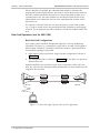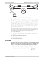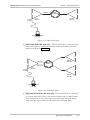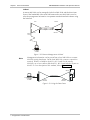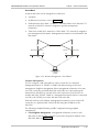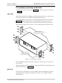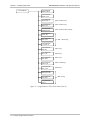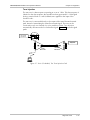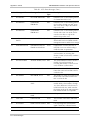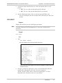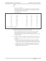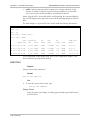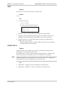
1
TM MX-2100/2104 Data, Voice, Fax and LAN Integrating Modular Multiplexer Installation and Operation Manual NOTICE This manual contains information that is proprietary to MICROWAVE DATA SYSTEMS, INC. No part of this publication may be reproduced in any form whatsoever without prior written approval by MICROWAVE DATA SYSTEMS, INC. No representation or warranties for fitness for any purpose other than what is specifically mentioned in this manual is made either by MICROWAVE DATA SYSTEMS, INC. or its agents. MICROWAVE DATA SYSTEMS, INC. reserves the right to revise this publication and make changes without obligation to notify any person of such revisions or changes. For further information contact MICROWAVE DATA SYSTEMS, INC. at the address below or contact your local distributor. MICROWAVE DATA SYSTEMS, INC. 175 SCIENCE PARKWAY ROCHESTER, NY 14620-4261 U.S.A. Tel: General Business: Customer Service: Fax All Services: Internet E-mail: World Wide Web: 2002 Microwave Data Systems, Inc. +1 (716) 242-9600 +1 (800) 474-0964 +1 (716) 242-9620 [email protected] http://www. microwavedata.com Pub. No. 8011130000 SAFETY WARNINGS Always observe standard safety precautions during installation, operation and maintenance of this product. Only qualified and authorized service personnel should carry out adjustment, maintenance or repairs to this instrument. No adjustment, maintenance or repairs should be performed by either the operator or the user. WARRANTY FOR PRODUCTS MANUFACTURED BY MICROWAVE DATA SYSTEMS, INC. A. MICROWAVE DATA SYSTEMS, INC. (MDS) products, except as stated otherwise in an applicable price list, are warranted against defects in workmanship and material for a period of one (1) year from date of delivery as evidenced by MDS's packing slip or other transportation receipt. B. MDS’s sole responsibility under this warranty shall be to either repair or replace, at its option, any component which fails during the applicable warranty period because of a defect in workmanship and material, provided PURCHASER has promptly reported same to MDS in writing. All replaced Products or parts shall become MDS's property. C. MDS will honor the warranty at MDS's repair facility in Rochester, New York. It is PURCHASER's responsibility to return, at its expense, the allegedly defective Product to MDS. PURCHASER must obtain a Return Material Authorization (RMA) number and shipping instructions from MDS prior to returning any Product under warranty. Transportation charges for the return of the Product to PURCHASER shall be paid by MDS within the United States. For all other locations, the warranty excludes all costs of shipping, customs clearance and other related charges. If MDS determines that the Product is not defective within the terms of this warranty, PURCHASER shall pay MDS all costs of handling, transportation and repairs at the then prevailing repair rates. D. All the above warranties are contingent upon proper use of the Product. These warranties will not apply (i) if adjustment, repair or parts replacement is required because of accident, unusual physical, electrical or electromagnetic stress, neglect, misuse, failure of electric power, environmental controls, transportation, not maintained in accordance with MDS specifications, or abuses other than ordinary use; (ii) if the Product has been modified by PURCHASER or has been repaired or altered outside MDS's repair facility, unless MDS specifically authorizes such repairs or alterations; (iii) where MDS serial numbers, warranty data or quality assurance decals have been removed or altered. E. MDS also reserves the right to make product improvements without incurring any obligation or liability to make the same changes in Products previously manufactured or purchased. In no event shall MDS be liable for any breach of warranty in an amount exceeding the net selling price of any defective Product. No person, including any dealer, agent or representative of MDS is authorized to assume for MDS any other liability on its behalf except as set forth herein. Non-payment of any invoice rendered within the stated payment terms automatically cancels any warranty or guarantee stated or implied. If any payment is due MDS for services performed hereunder, it shall be subject to the same payment terms as the original purchase. F. EXCEPT FOR THE EXPRESS WARRANTIES STATED HEREIN, MDS DISCLAIMS ALL WARRANTIES ON PRODUCTS FURNISHED HEREUNDER, INCLUDING, WITHOUT LIMITATION, ALL IMPLIED WARRANTIES OF MERCHANTABILITY AND FITNESS; and the stated express warranties are in lieu of all obligations or liabilities on the part of MDS arising out of or in connection with the performance of the Products. WARRANTY FOR PRODUCTS MANUFACTURED BY OTHERS A. For products not manufactured by MDS, the original manufacturer's warranty shall be assigned to PURCHASER to the extent permitted and is in lieu of any other warranty, expressed or implied. B. For warranty information on a specific product, a written request should be made to MDS. FCC-15 User Information This equipment has been tested and found to comply with the limits of the Class A digital device, pursuant to Part 15 of the FCC rules. These limits are designed to provide reasonable protection against harmful interference when the equipment is operated in a commercial environment. This equipment generates, uses and can radiate radio frequency energy and, if not installed and used in accordance with the instruction manual, may cause harmful interference to the radio communications. Operation of this equipment in a residential area is likely to cause harmful interference in which case the user will be required to correct the interference at his own expense. Preface Foreword This manual describes the MX-2100/2104 family of data, voice, fax and LAN integrating modular multiplexers. The manual covers the general system characteristics, presents typical system applications, and provides installation, operating procedure and configuration information for the modules that are part of the basic MX-2100/2104 system configuration. This release of the manual covers the characteristics of equipment equipped with the Common Logic Module running software version 3.1 and above. Manual Organization This manual is organized as follows: Chapter 1. General Information presents the main features and typical applications of the MX-2100/2104 family, describes the various equipment versions, and lists the technical characteristics of the MX-2100/2104 systems. Chapter 2. Installation provides detailed installation and operation instructions for MX-2100/2104 systems. Chapter 3. Configuring MX-2100 provides general instructions for using and managing MX-2100/2104 systems by means of terminals and Telnet hosts. Chapter 4. Operation provides typical configuration procedures for MX-2100/2104 systems. Chapter 5. Diagnostics describes the diagnostic and performance monitoring functions supported by MX-2100/2104 systems. Appendix A. Connection Data provides connection data for the basic modules used in the MX-2100/2104 system. Appendix B. Alarms explains the alarms and configuration error messages generated by the MX-2100/2104 system. Appendix C. SNMP Management describes the SNMP and IP environments, and provides background information regarding the handling of management traffic. Appendix D. Software Download provides instructions for the installation of new software releases. Appendix E. Configuration Parameters lists the various parameters that can be used to configure MX-2100/2104. Appendix F. Command Set Description describes MX-2100/2104 commands. Conventions Note A note draws attention to a general rule for a procedure, or to exceptions to a rule. Caution A caution warns of possible damage to the equipment if a procedure is not followed correctly. Warning A warning alerts to the presence of important operating and maintenance (servicing) instructions in the literature accompanying the equipment. If these instructions are not followed exactly, bodily injury may occur. Related Documentation In addition to this system manual, separate Installation and Operation Manuals are available for each of the modules that are used in the MX-2100/2104 systems. Each module’s Installation and Operation Manual presents the technical characteristics, applications and specific configuration information for that module. Note that when the module manual refers to the respective MX-2000 or MX-2004 system Installation and Operation Manual, refer to the corresponding section of this system manual. Quick Start Guide This Quick Start Guide is a brief step by step guide to setting up and using your MX-2100. It is a supplement to the MX-2100/2104 Installation and Operation Manual. 1. Installing MX-2100 To install MX-2100 (for more detailed instructions refer to the System Installation and Setup chapter): 1. Unpack the equipment. 2. Check that your site conforms to the equipment requirements (refer to Site Requirements in the System Installation and Setup chapter). 3. Check the power supply rating considerations (refer to Power Supply Rating Considerations in the System Installation and Setup chapter). 4. Install the MX-2100 enclosure (refer to Installation and Setup in the System Installation and Setup chapter). 5. Install an additional KPS module if necessary (refer to Installation and Setup in the System Installation and Setup chapter). 6. Install the KM-Ringer module (refer to Installation and Setup in the System Installation and Setup chapter). 7. Connect the power cable, the KM-Ringer module, the Supervisory Port (KCL.2 module), the KML module, option modules and I/O modules (refer to Interfaces and Connections in the System Installation and Setup chapter). 8. Set the IP address using the DEF AGENT (refer to DEF AGENT in the Command Set Description appendix). 2. Operating MX-2100 To operate MX-2100 (for more detailed instructions refer to Operating Instructions in the Operation chapter): 1. If MX-2100 includes a KM-Ringer module, set the KM-Ringer module power switch to OFF. 2. Turn on MX-2100 by setting the ON/OFF switches (on the rear panels) to ON. 3. Check the front-panel indications (refer to Operating Instructions in the Operation chapter). Operating MX-2100 1 MX-2100/2104 Installation and Operation Manual Quick Start Guide 4. If MX-2100 includes a KM-Ringer module, turn it on by setting its POWER switch to ON. Verify that the RING VOLTAGE and BATTERY VOLTAGE indicators light. 5. Check the MX-2100 configuration (refer to Checking Current Operating Configuration in the Operation chapter). 6. Check the normal MX-2100 operating indications (refer to Normal Indications in the Operation chapter). 7. MX-2100 has diagnostic functions which can be used to test the proper operation of the MX-2100 system and identify the faulty components. For an explanation of the MX-2100 diagnostic functions refer to the Diagnostics chapter. 8. Turn off MX-2100 as follows: - If MX-2100 includes a KM-Ringer module, then turn off the KM-Ringer before MX-2100. - For the MX-2100’s KPS modules and MX-2104, set the ON/OFF switches (on the rear panels) to OFF. 3. Setting-Up the Local Configuration To set-up the MX-2100 local configuration (for more detailed information refer to Setting Configuration Parameters in the Configuring MX-2100 chapter): 1. Set the system parameters refer to Configuring the System Parameters in the Configuring MX-2100 chapter). 2. Select the main link parameters (refer to Configuring the Main Link Parameters in the Configuring MX-2100 chapter). 3. Select the channel parameters (refer to Configuring the Channel Parameters in the Configuring MX-2100 chapter). 4. Controlling MX-2100 from a Supervisory Port To control MX-2100 from a supervisory port (for more detailed instructions refer to Operating Instructions in the Operation chapter): 1. Start a session for MX-2100 (refer to Starting a Session - Single MX-2100 and Starting a Session - Multiple MX-2100 in the Operation chapter). 2. Type the desired commands after the working prompt and press Enter to execute the command. Refer to the Command Set Description appendix for a list of commands available. 3. End the control session by typing EXIT. You can now control MX-2100 from the front panel (refer to General Front Panel Operating Instructions in the Configuring MX-2100 chapter). 2 Controlling MX-2100 from a Supervisory Port Contents Chapter 1 General Information 1.1 FUNCTIONAL DESCRIPTION .................................................................................................1-1 Main System Features ..............................................................................................1-1 System Supervision and Configuration......................................................................1-4 Diagnostic Capabilities.............................................................................................1-6 1.2 PHYSICAL DESCRIPTION ......................................................................................................1-6 MX-2100, General Description ................................................................................1-6 MX-2100 Rear Panel................................................................................................1-7 MX-2100 Front Panel...............................................................................................1-8 MX-2104, General Description ................................................................................1-8 MX-2104 Rear Panel................................................................................................1-9 MX-2104 Front Panel.............................................................................................1-10 Common Logic Modules........................................................................................1-10 Main Link Modules ................................................................................................1-10 Power Supply Modules ..........................................................................................1-11 Option Modules (not for MX-2104)........................................................................1-12 I/O Modules ..........................................................................................................1-12 1.3 APPLICATION CONSIDERATIONS.........................................................................................1-16 Basic MX-2100 System...........................................................................................1-16 Redundancy (not for MX-2104)..............................................................................1-20 Dual Link Operation (not for MX-2104) .................................................................1-22 Priority Bumping (not for MX-2104) .......................................................................1-27 Switched Backup Operation (not for MX-2104) ......................................................1-28 Switch Mode .........................................................................................................1-30 System Management..............................................................................................1-32 System Timing Considerations................................................................................1-38 Data Channel Clock Modes ...................................................................................1-45 Timing Modes of ISDN Channels ...........................................................................1-46 Sub Link Timing.....................................................................................................1-47 Main Link Interface Characteristics .........................................................................1-47 1.4 I/O MODULE APPLICATIONS .............................................................................................1-50 1.5 TECHNICAL SYSTEM CHARACTERISTICS ................................................................................1-50 Chapter 2 Installation 2.1 INTRODUCTION ................................................................................................................2-1 2.2 SITE REQUIREMENTS AND PREREQUISITES...............................................................................2-2 Input Power Requirements.......................................................................................2-2 Grounding ...............................................................................................................2-2 Channel Connection Considerations ........................................................................2-3 Front and Rear Panel Clearance ...............................................................................2-3 Ambient Requirements ............................................................................................2-3 Electromagnetic Compatibility Considerations ..........................................................2-3 Current and Power Requirements of MX-2100 Power Supply Modules.....................2-3 Current and Power Capabilities of MX-2100 Power Supply Modules ........................2-6 Ratings of Ring and Feed Voltage Supplies................................................................2-7 2.3 EQUIPMENT NEEDED..........................................................................................................2-8 Terminal Characteristics ...........................................................................................2-8 Software Requirements ............................................................................................2-8 MX-2100/2104 Installation and Operation Manual i Table of Contents Supervisory Port Interface Characteristics .................................................................2-8 Connection of Supervision Terminal.........................................................................2-9 2.4 PACKAGE CONTENTS........................................................................................................2-11 2.5 INSTALLATION AND SETUP OF MX-2100.............................................................................2-12 MX-2100 ...............................................................................................................2-12 MX-2104 ...............................................................................................................2-12 KPS Module...........................................................................................................2-13 KCL.2 Module .......................................................................................................2-14 2.6 INTERFACES AND CONNECTIONS ........................................................................................2-16 KPS Module...........................................................................................................2-16 KCL.2 Module .......................................................................................................2-17 Connections to KML, Options, I/O Modules, and Ringers .......................................2-19 MX-2104 ...............................................................................................................2-19 2.7 INITIAL SETUP AND CONFIGURATION ..................................................................................2-21 Chapter 3 Configuring MX-2100 3.1 INTRODUCTION ................................................................................................................3-1 3.2 CONTROL OF MX-2100 OPERATION ...................................................................................3-1 General ...................................................................................................................3-1 Front Panel Operating Instructions ...........................................................................3-2 Front Panel Menu ....................................................................................................3-2 3.3 SETTING CONFIGURATION PARAMETERS ................................................................................3-7 General Configuration Procedure.............................................................................3-7 Configuring the System Parameters ..........................................................................3-9 Configuring the Main Link Parameters....................................................................3-11 Configuring the Channel Parameters ......................................................................3-11 Configuring the SP Parameters .................................................................................3-12 Chapter 4 Operation 4.1 GENERAL..........................................................................................................................4-1 4.2 MX-2100 SUPERVISION LANGUAGE .....................................................................................4-1 Command Language Syntax .....................................................................................4-1 Command Options ..................................................................................................4-2 Command Protocol..................................................................................................4-3 Index of Commands ................................................................................................4-4 4.3 FRONT PANEL CONTROLS AND INDICATORS ..........................................................................4-7 Organization of MX-2100 Display ............................................................................4-9 Using the Front Panel Push-buttons..........................................................................4-9 Checking Current Operating Configuration.............................................................4-10 Normal Indications ................................................................................................4-12 4.4 OPERATING INSTRUCTIONS ...............................................................................................4-12 Supervision Terminal .............................................................................................4-12 Front Panel ............................................................................................................4-16 Chapter 5 Diagnostics 5.1 ALARMS ...........................................................................................................................5-1 5.2 DIAGNOSTIC TESTS ............................................................................................................5-1 MX-2100 TEST OPTIONS, General ..........................................................................5-1 Test Options Operating Instructions .........................................................................5-3 MX-2100 Diagnostic Functions, General ..................................................................5-7 Main Link Loops ......................................................................................................5-8 I/O Module Loops and Tests ..................................................................................5-12 ii MX-2100/2104 Installation and Operation Manual Table of Contents Appendix A Connection Data A.1 A.2 A.3 A.4 A.5 SCOPE .......................................................................................................................... A-1 SUPERVISORY PORT CONNECTOR ...................................................................................... A-1 MNG CONNECTOR ........................................................................................................ A-3 ALARM RELAY CONNECTOR .............................................................................................. A-4 DC POWER INPUT CONNECTOR ....................................................................................... A-4 Appendix B Alarms B.1 ALARM MESSAGES .............................................................................................................B-1 B.2 CONFIGURATION ERROR MESSAGES ...................................................................................B-10 Appendix C SNMP Management C.1 SCOPE ............................................................................................................................ C-1 C.2 SNMP ENVIRONMENT ...................................................................................................... C-1 General .................................................................................................................. C-1 SNMP Principles ..................................................................................................... C-1 Management Domains Under SNMP ...................................................................... C-3 C.3 IP ENVIRONMENT ............................................................................................................ C-4 General .................................................................................................................. C-4 IP Environment ....................................................................................................... C-5 Automatic IP Traffic Routing.................................................................................... C-6 C.4 SNMP TRAPS .................................................................................................................. C-8 Appendix D Software Download D.1 SCOPE .......................................................................................................................... D-1 D.2 COLD (LOCAL) INSTALLATION PROCEDURE ......................................................................... D-1 Preparations ........................................................................................................... D-1 Downloading Procedure - MX-2100 with Single KCL.2............................................ D-2 D.3 WARM INSTALLATION (UPGRADING) PROCEDURE - WINDOWS-BASED STATIONS ..................... D-3 Preparations ........................................................................................................... D-3 Downloading Procedure ......................................................................................... D-3 Appendix E Configuration Parameters E.1 GENERAL .......................................................................................................................... E-1 System Configuration Parameters ............................................................................. E-1 Main Link Configuration Parameters......................................................................... E-3 Supervisory Port Configuration Parameters ............................................................... E-7 Appendix F Command Set Description F.1 GENERAL .......................................................................................................................... F-1 F.2 COMMANDS ..................................................................................................................... F-2 BYE ......................................................................................................................... F-2 CLR ALM................................................................................................................. F-2 CLR LOOP .............................................................................................................. F-3 CLR MONITOR ....................................................................................................... F-4 CONNECT SWITCH ................................................................................................ F-4 DATE....................................................................................................................... F-5 DEF AGENDA.......................................................................................................... F-6 DEF AGENT............................................................................................................. F-7 MX-2100/2104 Installation and Operation Manual iii Table of Contents DEF ALM DEBOUNCE............................................................................................. F-9 DEF CALL................................................................................................................ F-9 DEF CH................................................................................................................. F-12 DEF CON .............................................................................................................. F-12 DEF DB FLIP.......................................................................................................... F-14 DEF DP ................................................................................................................. F-15 DEF FRAME........................................................................................................... F-17 DEF MANAGER LIST.............................................................................................. F-18 DEF ML ................................................................................................................. F-19 DEF ML CALL........................................................................................................ F-20 DEF NAME ............................................................................................................ F-24 DEF NODE............................................................................................................ F-24 DEF NP ................................................................................................................. F-25 DEF PWD.............................................................................................................. F-26 DEF ROUTE .......................................................................................................... F-27 DEF SP .................................................................................................................. F-28 DEF SYS................................................................................................................. F-29 DISCONNECT SWITCH ........................................................................................ F-32 DSP AGENT .......................................................................................................... F-33 DSP ALM............................................................................................................... F-34 DSP BERT.............................................................................................................. F-34 DSP CH CON........................................................................................................ F-35 DSP FLIP ............................................................................................................... F-36 DSP HDR TST ....................................................................................................... F-37 DSP MANAGER LIST ............................................................................................. F-37 DSP KVF5 or DSP PBX........................................................................................... F-38 DSP KVF6.............................................................................................................. F-39 DSP SIGNALING or DSP SIG ................................................................................. F-40 DSP PRBS_INJ ....................................................................................................... F-40 DSP REM AGENT .................................................................................................. F-41 DSP REV................................................................................................................ F-41 DSP ST FRAME ...................................................................................................... F-42 DSP ST ML ............................................................................................................ F-44 DSP ST SLOT......................................................................................................... F-46 DSP ST SYS............................................................................................................ F-48 EDIT DB ................................................................................................................ F-50 EXIT....................................................................................................................... F-50 F............................................................................................................................ F-51 FLIP ML................................................................................................................. F-51 HELP ..................................................................................................................... F-52 INIT DB................................................................................................................. F-52 INIT F.................................................................................................................... F-53 LOAD DB 1\2........................................................................................................ F-54 LOAD IO............................................................................................................... F-54 LOOP.................................................................................................................... F-55 ML RECOVERY ...................................................................................................... F-56 MONITOR ............................................................................................................ F-56 REBUILD FRAME................................................................................................... F-56 RESET LOC............................................................................................................ F-57 RESET IO............................................................................................................... F-57 RESET ML.............................................................................................................. F-57 TIME ..................................................................................................................... F-58 UPDATE DB 1\2 .................................................................................................... F-58 iv MX-2100/2104 Installation and Operation Manual Table of Contents List of Figures Figure 1-1. MX-2100 System Applications.......................................................................... 1-2 Figure 1-2. “V” Configuration ............................................................................................ 1-5 Figure 1-3. MX-2100 Enclosure with Modules, General View............................................. 1-7 Figure 1-4. MX-2100 Enclosure, Rear View........................................................................ 1-8 Figure 1-5. MX-2100 Enclosure Front Panel ....................................................................... 1-8 Figure 1-6 MX-2104 Enclosure, General View................................................................... 1-9 Figure 1-7. MX-2104 Enclosure, Rear View........................................................................ 1-9 Figure 1-8. MX-2104 Enclosure Front Panel ..................................................................... 1-10 Figure 1-9. Basic MX-2100 System Structure.................................................................... 1-16 Figure 1-10. Redundant MX-2100 System ....................................................................... 1-21 Figure 1-11. Dual Link, High Capacity Point-to-Point Application .................................... 1-22 Figure 1-12. Dual Link System, Independent Link Application ......................................... 1-23 Figure 1-13. Basic Bypassing Configuration ...................................................................... 1-24 Figure 1-14. Bypassing Parameters................................................................................... 1-25 Figure 1-15. Typical Bypassing Application ...................................................................... 1-26 Figure 1-16. Typical KDI Bypassing and Multidrop Application ........................................ 1-27 Figure 1-17. Typical Switched Backup Configuration ....................................................... 1-29 Figure 1-18. Typical ISDN Switched Backup Application ................................................. 1-30 Figure 1-19. Single Switch Mode ..................................................................................... 1-31 Figure 1-20. Dual Switch Mode ....................................................................................... 1-31 Figure 1-21. Single and Switch Mode............................................................................... 1-32 Figure 1-22. Remote Management: In-Band .................................................................... 1-34 Figure 1-23. Using the Data Frame .................................................................................. 1-34 Figure 1-24. Remote Management: Out-of-Band............................................................. 1-35 Figure 1-25. Local Neighbor Management ....................................................................... 1-36 Figure 1-26. Remote Neighbor Management ................................................................... 1-36 Figure 1-27. Network Configurations Using DTE Timing .................................................. 1-39 Figure 1-28. Typical External DCE Timing Application ..................................................... 1-41 Figure 1-29. Typical DCE (KML.1–4) Timing Application.................................................. 1-42 Figure 1-30. Typical Internal Timing Mode Application.................................................... 1-42 Figure 1-31. Typical Loopback Timing Application........................................................... 1-43 Figure 1-32. Typical DCE from I/O Timing Mode Application (KML.7, KML.8, KML.F) .... 1-43 Figure 1-33. Typical DCE from ML Timing Mode Application (KML.7, KML.8, KML.F) ..... 1-44 Figure 1-34. Clock Mode 1 (DCE) .................................................................................... 1-45 Figure 1-35. Clock Mode 2 (DTE1) .................................................................................. 1-45 Figure 1-36. Clock Mode 3 (DTE2) .................................................................................. 1-46 Figure 2-1. Attachment of Brackets .................................................................................. 2-12 Figure 2-2. Typical KPS Module, Location of Internal Jumper........................................... 2-13 Figure 2-3. Module KCL.2, Internal Switch and Jumpers .................................................. 2-14 Figure 2-4. KPS Modules, Rear Panels.............................................................................. 2-17 Figure 2-5. Module KCL.2, Rear Panel ............................................................................. 2-18 Figure 2-6. MX-2104 Enclosure, Typical Rear View.......................................................... 2-19 MX-2100/2104 Installation and Operation Manual v Table of Contents Figure 3-1. Organization of Front Panel Menu (Part I) ........................................................ 3-4 Figure 3-2. Organization of Front Panel Menu (Part II) ....................................................... 3-5 Figure 3-3. Organization of Front Panel Menu (Part III) ...................................................... 3-6 Figure 4-1. MX-2100 Front Panel....................................................................................... 4-7 Figure 4-2. MX-2104 Front Panel....................................................................................... 4-7 Figure 4-3. Indicator Functions .......................................................................................... 4-8 Figure 5-1. Local Main Link Loop, Signal Path.................................................................... 5-9 Figure 5-2. Remote Main Link Loop, Signal Paths ............................................................ 5-10 Figure 5-3. Main Link Modem Loop 3, Signal Path........................................................... 5-11 Figure 5-4. Main Link Modem Loop 2, Signal Path........................................................... 5-12 Figure 5-5. I/O Module, Local Loop on Individual Channel.............................................. 5-13 Figure 5-6. I/O Module, Remote Loop on Individual Channel.......................................... 5-13 Figure 5-7. Voice I/O Module, Test Tone Injection Path................................................... 5-15 Figure C-1. IP Address Classes............................................................................................C-5 Figure C-2. Management System Topology Using Subnetting .............................................C-7 List of Tables Table 1-1. MX-2100 Multiplexing Data............................................................................ 1-17 Table 1-2. Bandwidth Allocations .................................................................................... 1-19 Table 1-3. Example of Bandwidth Allocations .................................................................. 1-20 Table 1-4. KML.F Fiber-Optic Interface Characteristics .................................................... 1-49 Table 2-1. Power Consumption of MX-2100 Modules ....................................................... 2-4 Table 2-2. Nominal Power Consumption of Power Supply Modules .................................. 2-6 Table 2-3. DCE and DTE Interfacing Mode - Control Lines ................................................ 2-9 Table 2-4. MNG Connector - Control Lines ..................................................................... 2-11 Table 2-5. Module KCL.2, Internal Switch and Jumper Functions..................................... 2-14 Table 2-6. KPS Modules, Rear Panels............................................................................... 2-16 Table 2-7. Module KCL.2, Rear Panel .............................................................................. 2-18 Table 2-8. MX-2104, Rear Panel Components ................................................................. 2-20 Table 2-9. Typical Terminal Control Sequences ............................................................... 2-22 Table 3-1. MX-2100 Front Panel Configuration Parameters................................................ 3-3 Table 3-2. Procedure for Performing Configuration Activity ............................................... 3-8 Table 4-1. General Command Options .............................................................................. 4-2 Table 4-2. MX-2100 Command Set Index.......................................................................... 4-4 Table 4-3. MX-2100 Controls, Connectors, and Indicators ................................................. 4-8 Table 4-4. Instructions for Displaying Current Configuration Parameters .......................... 4-11 vi MX-2100/2104 Installation and Operation Manual Table of Contents Table 5-1. Deactivating all the Tests................................................................................... 5-3 Table 5-2. Activating / Deactivating the Monitoring of a Selected Channel ......................... 5-4 Table 5-3. Activating / Deactivating a Main Link Loop........................................................ 5-5 Table 5-4. Activating / Deactivating a Channel Loop .......................................................... 5-6 Table A-1. Common Logic Module KCL.2, Supervisory Port Connector Pin Allocations for DCE Emulation.............................................................................................A-1 Table A-2. Common Logic Module KCL.2, Supervisory Port Connector Pin Allocations for DTE Emulation .............................................................................................A-2 Table A-3. Common Logic Module KCL.2, MNG Connector Pin Allocations ......................A-3 Table A-4. Alarm Relay Connector Pinout.........................................................................A-4 Table B-1. LCD Alarm Messages ........................................................................................ B-1 Table C-1. IP Address Class................................................................................................C-5 Table E-1. System Parameters ............................................................................................ E-1 Table E-2. Main Link Parameters........................................................................................ E-4 Table E-3. Supervisory Port Parameters .............................................................................. E-7 Table F-1. Call-out Parameters......................................................................................... F-10 Table F-2. Dial-out Parameters ........................................................................................ F-16 Table F-3. Network Parameters....................................................................................... F-26 Table F-4. Terminal Programmed Parameters .................................................................. F-28 Table F-5. System Parameters .......................................................................................... F-30 Table F-6. MX-2100 Default Configuration Used with Supervision Terminal .................... F-53 Table F-7. Codes Used by Typical Terminals.................................................................... F-54 MX-2100/2104 Installation and Operation Manual vii Table of Contents viii MX-2100/2104 Installation and Operation Manual Chapter 1 General Information 1.1 Functional Description MX-2100/2104 is an advanced, highly versatile user-configurable modular TDM (Time Division Multiplex) system. The MX-2100/2104 system provides an efficient and cost-effective method for transmitting data, voice and fax over digital data services. Access to these services is provided over a variety of standard interfaces (V.35, RS-530/V.36, RS-232/V.24, X.21, Standard DDS, codirectional G.703, ISDN, fiber optic, T1, and E1), at data rates ranging from 9.6 to 1536 kbps. Bandwidth utilization efficiency is 98.5%. Main System Features The MX-2100/2104 system can be equipped with various types of input/output (I/O) modules that provide the required interface for the user data, fax, and voice channels. The series of I/O modules includes: • High-speed synchronous data modules operating at a rate of 2.4 through 614.4 kbps – the KHS series of modules • Low-speed data modules (300 bps to 57.6 kbps or 64 kbps) synchronous and asynchronous data channels, including statistical multiplexing modules – the KLS series of modules • ISDN interface modules – the KHS.U series and KVF.4/S0 series • 2W and 4W multiple voice channel interface modules that can directly connect to PBX lines and two-wire telephone sets – the KVC series of modules • 2W and 4W interface voice/fax low bit rate KVF.4 and KVF.8 modules • T1 and E1 PBX trunk interface KVF.5 and KVF.6 modules • Token ring extender module, KTRE • Ethernet Bridge/Router module, KMBE • Bypass and multidrop module, KDI (not applicable for MX-2104). Detailed information on the specific MX-2100 modules can be found in the separate module Installation and Operation Manuals. The 3U high MX-2100 unit can be equipped with up to 12 I/O modules. 1U high MX-2104 unit can be equipped with up to 4 I/O modules. Functional Description 1-1 MX-2100/2104 Installation and Operation Manual Chapter 1 General Information Note In this manual, the generic term MX-2100 is used when the information is applicable to both MX-2100 and MX-2104 equipment versions. If the information is applicable to only a particular equipment version, this will be specified. Figure 1-1 illustrates the basic capabilities of the MX-2100 system. Network Management Station Ethernet Network PABX Trunk Line Tie Lines Fax Ethernet Port KCL KML I/O Modules KVF.4 KVF.4 KVF.5 KVC.1M KVC.1M KLS.1 KLS.1 KLS.1 KLS.2 KHS.1 KHS.1 KVF.4 MX-2100 SP Port or SLIP Stat Mux Terminal Modem SDM Mux Supervision Terminal or TELNET or SNMP MX-2100 CAD/CAM Fax Figure 1-1. MX-2100 System Applications 1-2 Functional Description -V.35 -RS-530/V.36 -RS-232/V.24 -X.21 -G.703 Codirectional -Standard DDS -ISDN -E1 -T1 -Fiber-Optic MX-2100/2104 Installation and Operation Manual Chapter 1 General Information The MX-2104 system can be equipped with only one main link. The 3U high MX-2100 system can be equipped with two main link modules. Two main link modules in an MX-2100 system, can be used in several ways: • To provide hot-standby redundancy (backup) for the main link, with automatic or manual switchover in case one of the links fails. For maximum flexibility, MX-2100 allows the preparation of a different configuration for use on the backup link. The backup link can also use a switched data circuit. The switched circuit can be established on a PSTN line, using analog modems, or on an ISDN line using an S or U interface. • To provide two independent links from the same MX-2100 enclosure. The two links can operate at different data rates. The dual-link mode can also be used for providing the equivalent of hot standby protection to critical data channels (by enabling the priority bumping feature). • To provide multidrop and bypass capabilities (using a dedicated KDI module). In addition to main link redundancy, the MX-2100 system reliability can be further enhanced by installing an additional power supply unit in the enclosure. The power supplies share the load current, therefore when one of them fails or its input voltage is disconnected, the other takes over the full load without disturbance to MX-2100 operation. The MX-2100/2104 system provides flexible system timing options, with several main link, and channel timing modes. The main link timing modes are DTE, DCE, and external DCE. In the DCE and external DCE modes, the timing reference source can be selected by the user: • Internal oscillator • External (timing locked to one of the data channels) • The other main link module (provided a KDI module is installed). In addition to the main timing source, a fallback source can be selected. When the timing mode is DTE or external DCE, buffers are inserted in the main link signal paths, to absorb the expected jitter and timing instabilities. Normal buffer size is ±8 bits; for operation over satellite links, the receive buffer size can be increased to ±256 bits. The timing modes available for the data channels are programmable, thereby permitting each channel to be configured as either DCE (supplies receive and transmit clocks to the user's equipment), DTE1 (supplies the receive clock and accept a transmit clock), or DTE2 (accepts receive and transmit clocks from the user's equipment), with buffered retiming of the received data. Connection to the national network and to common-carrier data lines is also supported, with the external clock selectable as the source for system timing. For modules with ISDN, T1, E1, and fiber-optic interfaces, a loopback timing mode is available. This mode enables locking the MX-2100 timing to the accurate timing provided by the network to which the interface is connected. Functional Description 1-3 Chapter 1 General Information MX-2100/2104 Installation and Operation Manual System Supervision and Configuration The MX-2100 system is designed for unattended operation. A complete collection of operating parameters configures the MX-2100 system and each of its modules. This collection of operating parameters is determined by a database. This database is stored in the non-volatile memory of the MX-2100 control module. MX-2100 can store two different databases, and can be configured to switch automatically between the databases, in accordance with a predetermined daily schedule ("day/night" operation), or to use one of the databases only in case of switching to a backup link. MX-2100 supervision and minimal configuration functions can be performed from its front panel, using three push-buttons and an LCD display. For more detailed information, refer to Local Management on page 1-33. MX-2100 stores alarms detected during operation in a buffer. The buffer serving the front panel LCD can store one alarm of each type. The buffer for alarms to be sent to a supervision terminal can hold up to 100 alarms. During regular operation, a front panel indicator lights to indicate if there are any alarms in the alarm buffer. The local operator can then review the contents of the alarm buffer on the front panel LCD display, and can delete old alarms related to events that are no longer present in the system. In addition to the alarm buffer, the front-panel LED indicators display in real time the main link and power supply status and alert when test loops are present in the system. The front panel LED indicators can also be used to monitor on-line a selected user channel. The monitored functions are transmit and receive data activity, and the state of the RTS and DCD control lines (or E and M lines for voice channels). Local MX-2100 Management A local MX-2100 can be managed by any of the following: • MX-2100 front panel using push buttons and an LCD • ASCII terminal connection to the local MX-2100 • TELNET connection to the local MX-2100. The connection can be via SLIP or via an Ethernet LAN. The local MX-2100 requires an IP address. For information on assigning an IP address, refer to the DEF AGENT command in the Command Set Description appendix. • SNMP network management station connected to the local MX-2100. The connection can be via SLIP or via an Ethernet LAN. The local MX-2100 requires an IP address. For information on assigning an IP address, refer to the DEF AGENT command in the Command Set Description appendix. Remote MX-2100 Management A remote MX-2100 can be managed either in-band or out-of-band. For both, the remote MX-2100 requires an IP address. For information on assigning an IP address, refer to the DEF AGENT command in the Command Set Description appendix. 1-4 Functional Description MX-2100/2104 Installation and Operation Manual Chapter 1 General Information In-Band Management In-band management of a remote MX-2100 is performed via the local MX-2100 and the data frame. A connection to the local MX-2100 can be made through: • An Ethernet LAN • A SLIP connection. In both cases, management can be performed via TELNET. Some of the bandwidth of the main link between the two MX-2100s is used to relay the management information. In a “V” configuration, any one of the three MX-2100s can be considered the local MX-2100. The other two MX-2100s can be managed through the local MX-2100. KCL A Main Link Remote MX-2100 KCL A B Remote MX-2100 KCL Main Link B Local MX-2100 Supervision Terminal or TELNET or SNMP Figure 1-2. “V” Configuration The main link between the local MX-2100 and the remote MX-2100 can also be used to download software. Out-of-Band Management There are several options for managing a remote MX-2100 out-of-band: • Using a network management station or TELNET over a LAN connected to the remote MX-2100. The remote MX-2100 requires an IP address. For information on assigning an IP address, refer to the DEF AGENT command in the Command Set Description appendix. Functional Description 1-5 Chapter 1 General Information MX-2100/2104 Installation and Operation Manual • Using a network management station or TELNET via a SLIP connection to the remote MX-2100. The remote MX-2100 requires an IP address. For information on assigning an IP address, refer to the DEF AGENT command in the Command Set Description appendix. • Using an ASCII terminal via a modem connection to the SP port. Diagnostic Capabilities The MX-2100 system provides extensive diagnostics, supervision and maintenance capabilities for easy maintenance and rapid detection and location of faults. MX-2100 diagnostics include automatic self-test upon power-up, and on-line monitoring of critical functions. The system generates time stamped alarm messages that cover all the significant system events. The time stamp is provided by a real-time clock with battery backup. The system operator can then perform comprehensive testing on each type of module, to determine the cause of the alarm messages and return the system to normal operation. Various types of test loops are provided, including modem loops 2 and 3 per ITU-T Rec. V.54 for rapid isolation of the fault area, tone injection for rapid testing of voice interface modules, and pseudo-random sequence transmission test for checking the proper operation of data interface modules, and detection of bit errors. 1.2 Physical Description MX-2100, General Description The MX-2100 system consists of a 19" (3U) enclosure that contains 18 module slots. Five of the slots (slots 1 through 5) are assigned to the system modules: • The control subsystem • The main link (aggregate) interface subsystem • The system power supplies. Two slots each are assigned for KML and KPS modules, respectively, to provide support for the redundancy option: • Slots 1 and 2 - for KPS modules • Slots 3 and 4 - for KML modules. One slot (slot 6) is assigned for an options module (e.g., for the KDI or KAI modules). The other 12 slots are intended for I/O modules. Each I/O slot can accept any type of I/O module. All the modules are inserted through the rear panel. The cable connections are also made through the rear panel. Figure 1-3 shows a general view of a MX-2100, and identifies the functions of the enclosure slot. 1-6 Physical Description MX-2100/2104 Installation and Operation Manual Chapter 1 General Information Options Module 12 I/O Modules Common Logic Main Link Interface Sub-system Power Supply Sub-system Figure 1-3. MX-2100 Enclosure with Modules, General View MX-2100 Rear Panel Figure 1-4 shows a typical rear panel of the MX-2100 enclosure and identifies the slots and their use. Note the labels which designate the type of module that can be installed in each slot; in addition, each slot is keyed, therefore it is not possible to install the wrong module type. Physical Description 1-7 MX-2100/2104 Installation and Operation Manual Chapter 1 General Information Slot 1 2 3 4 5 6 7 8 9 10 11 System Slots 1 PS-A KPS 2 PS-B 3 ML-A KML.1 12 13 14 15 16 17 18 I/O Slots 4 ML-B 5 CL 6 KCL.2 OP 7 I/O1 8 I/O2 9 I/O3 10 I/O4 11 I/O5 13 I/O7 12 I/O6 14 I/O8 15 I/O9 17 I/O11 16 I/O10 18 I/O12 RESET TEST ALARM POWER ALM RLY Power Supply KCL Redundant KML Module Module Power Supply Options Redundant (Optional) KML Module Module (Optional) Power Supply Sub-system Main Link Interface Sub-system I/O Modules as Required Figure 1-4. MX-2100 Enclosure, Rear View MX-2100 Front Panel The front panel of the MX-2100 enclosure includes an LCD, three push-buttons, and labels for the show-through areas for the status indicators located on each system module. Note that the indicators are arranged in groups (one group for each system module), that are positioned before the corresponding module slot. Figure 1-5 shows the front panel of the MX-2100 enclosure. Refer to the Operation chapter for a description of the front panel functions. VOICE DATA ALARM TXD TEST RXD M-LEAD RTS E-LEAD DCD ON LINE ON LINE STATUS TXD RXD LOCAL LOS SYSTEM CURSOR CHANNEL SCROLL ENTER B REMOTE LOS A B A POWER SUPPLY MAIN LINK Figure 1-5. MX-2100 Enclosure Front Panel MX-2104, General Description The MX-2104 system consists of a 19" 1U enclosure with 4 slots for the installation of I/O modules. All the modules are inserted through the rear panel. The cable connections are also made through the rear panel. The front panel includes a control section with three push-buttons and a two-row LCD display (16 characters per row), and status and alarm indicators. The following figure shows a general view of a MX-2104 enclosure. 1-8 Physical Description MX-2100/2104 Installation and Operation Manual Chapter 1 General Information 4 I/O Modules Figure 1-6 MX-2104 Enclosure, General View The MX-2104 enclosure contains the control sub-system, the main link (aggregate) sub-system and the system power supply. The main link sub-system performs main link interfacing, multiplexing and demultiplexing functions, and provides the timing signals used by the I/O modules installed in the enclosure. MX-2104 Rear Panel The following figure shows a typical rear view of the MX-2104 enclosure and identifies the I/O slots. FUSE ALM Power RST TST ∼100-240VAC 0.8A T 250V ON CONTROL MNG 1234 ALM RLY X.21 Figure 1-7. MX-2104 Enclosure, Rear View Physical Description 1-9 MX-2100/2104 Installation and Operation Manual Chapter 1 General Information MX-2104 Front Panel The following figure shows the front panel of the MX-2104 enclosure. The front panel includes an LCD, three push-buttons, and status indicators. Refer to the Operation chapter for a description of the front panel functions. CURSOR SCROLL ENTER LOS REM LOC RX TX ON LINE TEST ALARM Figure 1-8. MX-2104 Enclosure Front Panel Common Logic Modules The MX enclosure requires one KCL.2 type common logic module. The main functions of the KCL.2 module are control of: • Multiplexing/demultiplexing operations • System management • Interfacing with the optional external system management. The KCL.2 module stores the MX-2100 database in non-volatile memory (NVRAM). The configuration information stored in the NVRAM is downloaded to the module installed in MX-2100 upon turn-on or after system reset. Therefore, during troubleshooting activities, it is possible to temporarily remove the KCL.2 module from the MX-2100 enclosure without disrupting system operation. If it is necessary to replace the KCL.2 module, the database can be transferred to a new module by installing the NVRAM taken from the original module in the replacement module. Main Link Modules The enclosure can accept one KML type main link interface module or, for MX-2100, two KML type main link interface modules. In addition to main link interfacing, the KML module performs the multiplexing and demultiplexing functions and provides the timing signals used by the other modules installed in the enclosure. Two KML modules are necessary for dual link configurations and for main link redundancy. The following main link interface modules are available: KML.1 - V.35 main link interface module KML.2 - V.24/RS-232 main link interface module KML.3 - V.36/RS-422/RS-530 main link interface module KML.4 - X.21 main link interface module KML.5 - G.703 codirectional main link interface module KML.6 - Standard DDS CSU/DSU main link interface module KML.7 - T1 main link interface module KML.8 - E1 main link interface module. 1-10 Physical Description MX-2100/2104 Installation and Operation Manual Chapter 1 General Information KML.10 - ISDN main link interface module. The module can be ordered in two versions: • KML.10/S with ISDN S-type interface. The "S" interface operates as Terminal Adapter (TE side), intended for connection to standard Network Termination (NT) unit. • KML.10/U with ISDN U-type interface. The "U" interface operates as Network Termination (NT side) unit, intended for connection to standard Line Termination (LT) unit. KML.F - Fiber-optic main link interface module (not for MX-2104). The module can be ordered with various types of optical interfaces (laser or LED transmitters for single-mode and multi-mode fiber-optic cable). For more information, see each main link module’s Installation and Operation Manual. Power Supply Modules The MX-2100 enclosure can accept one or two KPS type power supply modules. Several types of power supply modules are available: KPS.3 - 25W power supply module for -48 VDC power KPS.4 - 50W power supply module for 100 to 240 VAC mains KPS.5 - 25W power supply module for -24 VDC power KPS.6 - 56W power supply module for 100 to 240 VAC mains KPS.7 - 56W power supply module for -48 VDC mains. Two KPS modules are necessary for redundancy: when both modules are operational, they share the load, whereas in case of failure or loss of input power the remaining module continues to supply the power alone and there is no redundancy. Switch-over is automatic and does not disturb normal operation. The MX-2104 enclosure includes one power supply. The available types are: • AC - 30W power supply for 100 to 240 VAC mains • 48 - 40W power supply for -48 VDC mains. In addition to power supply modules, the MX-2100 enclosure supports one KM-Ringer module, for providing line feed and ring voltages for voice channels and phantom feed for ISDN lines. This module is available in AC (115 to 230 VAC) and DC (-24 VDC or -48 VDC) input voltage versions. The KM-Ringer can be installed as a plug-in module for MX-2100, or located on shelves or desktops. Physical Description 1-11 Chapter 1 General Information MX-2100/2104 Installation and Operation Manual Option Modules (not for MX-2104) The 3U MX-2100 system can accept two types of options module: KAI Alarm indication module for installation in the options position, or in any I/O slot. The KAI includes indicators similar to those located on the MX-2100 front panel. These indicators repeat all the relevant MX-2100 front panel indications on the rear panel, and thus complement the indicators available on the rear panels of the other modules. Maintenance activities are thus expedited, as all the MX-2100 indications become readily available on one side of the equipment. KDI Bypass and multidrop module. The KDI module can be installed in the option slot, or in any I/O slot. The KDI module enables direct transfer (bypassing) of a group of main link frame bits, in both directions, between the two main links of MX-2100. Channels that are not bypassed are connected to I/O modules of MX-2100. The KDI module is available in two versions: • KDI version: supports only the bypassing function • KDI/M version: also includes a data channel interface for one multidrop channel. The multidrop channel is compatible with the data channels of the KLS.1/NEW low-speed data module, and supports data rates in the range of 0.3 to 64 kbps. As is standard practice in a multidrop application, the receive path of the local multidrop channel continuously receives the data transferred in its allocated bandwidth on the desired main link (the same data is also bypassed to the other link, to make it available downstream), but its transmit path is connected to the main link only when the RTS line in the local interface is asserted. For more information, see the option module’s Installation and Operation Manual. I/O Modules MX-2100 supports up to 12 user-selected I/O modules. MX-2104 supports up to 4 user-selected I/O modules. Both units can accept any combination of the following types of I/O modules with power supply limitations. KVC.1 - ADPCM or PCM voice interface module, provides two voice channels. For more information, refer to the KVC.1 Installation and Operation Manual. The following versions are available: − KVC.1/E&M: four-wire or two-wire interface with E&M signaling per RS-464 Types I, II, III and V, and British Telecom SSDC5 − KVC.1/FXS: two-wire interface for direct connection to a telephone set − KVC.1/FXO: two-wire interface for direct connection to a PBX extension line. 1-12 Physical Description MX-2100/2104 Installation and Operation Manual • Chapter 1 General Information KVC.1M - ADPCM or PCM voice interface module, provides one or two voice channels and support error-free fax transmission. For more information, refer to the KVC.1M Installation and Operation Manual. The following versions are available: − KVC.1M/E&M: two voice channel with four-wire or two-wire interface with E&M signaling per RS-464 Types I, II, III and V, and British Telecom SSDC5 − KVC.1M/E&M48: similar to the KVC.1M/E&M, except that it requires an external -48 VDC source to supply the signaling voltage for increasing the maximum allowed line length − KVC.1M/FXS: two voice channels with two-wire interface for direct connection to a telephone set − KVC.1M/FXSP: similar to KVC.1M/FXS, except that it has an internal ringer and line feed supply − KVC.1M/FXO: two voice channels with two-wire interface and FXO loop start signaling for direct connection to a PBX extension line. • KVC.3 - Low-bit rate voice module, provides two high-quality compressed voice channels. For more information, refer to the KVC.3 Installation and Operation Manual. The following versions are available: − KVC.3/E&M: two voice channels with four-wire or two-wire interface with E&M signaling per RS-464 Types I, II, III and V, and British Telecom SSDC5 − KVC.3/FXS: two voice channels with two-wire interface for direct connection to a telephone set − KVC.3/FXSP: similar to KVC.3/FXS, except that it has an internal ringer and line feed supply − KVC.3/FXO: two voice channels with two-wire interface and FXO loop start signaling for direct connection to a PBX extension line. • KLS.1 - Low-speed RS-232 data module. For more information, refer to the KLS.1 Installation and Operation Manual. • KLS.2 - Low-speed RS-232 four-channel asynchronous statistical data module. For more information, refer to the KLS.2 Installation and Operation Manual. • KHS.1 - High-speed data interface module, provides two high-speed V.35, RS-530 or RS-449/RS-422 data channels. For more information, refer to the KHS.1 Installation and Operation Manual. • KHS.2 - Two-channel synchronous data module. For more information, refer to the KHS.2 Installation and Operation Manual. Physical Description 1-13 Chapter 1 General Information • MX-2100/2104 Installation and Operation Manual KHS.U - Data interface module, provides one or two ISDN basic access rate type "U" interfaces. The KHS.U module enables the extension of ISDN lines over non-ISDN facilities. For more information, refer to the KHS.U Installation and Operation Manual. The following versions are available: − KHS.U/S with one "U" interface − KHS.U/D with two "U" interfaces. • KHS.703 – High-speed data module that provides two independent 64 kbps codirectional data channels per ITU-T Rec. G.703. Each module is terminated with an RJ-45 eight pin connector. For more information, refer to the KHS.703 Installation and Operation Guide, further on in this manual. • KVF.4 - Voice/fax relay module using advanced digital signal processing (DSP) techniques (MPMLQ in accordance with ITU-T Rec. G.723.1) to provide one or two channels for transmission of voice and standard Group III fax signals over the MX-2100 link with automatic switch-over between voice and fax modes. For more information, refer to the KVF.4 Installation and Operation Manual. The following versions are available: − KVF.4/E&M: two channels with four-wire or two-wire interface with E&M signaling per RS-464 Types I, II, III and V, and British Telecom SSDC5 − KVF.4/E&M/E: similar to the KVF.4/E&M, except that it requires an external -48 VDC source to supply the signaling voltage for increasing the maximum allowed line length − KVF.4/FXS: two voice channels with two-wire interface for direct connection to a telephone set − KVF.4/FXS3: similar to KVF.4/FXS, except that it supports pulse metering and polarity reversal − KVF.4/FXSP: similar to KVF.4/FXS, except that it has an internal ringer and line feed supply − KVF.4/FXSW: one channel similar to the channels of the KVF.4/FXS, and one two-wire interface operating with FXO signaling, intended for connection to the PSTN, or to a PBX extension line − KVF.4/FXO: two channels with two-wire interface and FXO loop start signaling for direct connection to a PBX extension line − KVF.4/FXO3: similar to KVF.4/FXO, except that it supports pulse metering and polarity reversal − KVF.4/S0: one ISDN basic rate access type "S" interface for direct connection to an ISDN PBX. 1-14 Physical Description MX-2100/2104 Installation and Operation Manual • Chapter 1 General Information KVF.5 - Voice/fax relay module with T1 or E1 PBX trunk interface, uses advanced digital signal processing (DSP) techniques (MPMLQ - Multipulse Maximum Likelihood Quantization in accordance with ITU-T Rec. G.723.1) to allow the transmission of Group III facsimile and high-quality compressed voice signals while requiring, for each channel, a bandwidth of only 4.8, 6.4, 7.2, 9.6, or 12.8 kbps on the MX-2100 main link. For more information, refer to the KVF.5 Installation and Operation Manual. The following versions are available: − KVF.5/T1/M: KVF.5 "master" module with balanced T1 sub link interface, for connection to PBXs − KVF.5/E1/M: KVF.5 "master" module with balanced and unbalanced E1 sub link interfaces, for connection to PBXs − KVF.5/T1/S: basic KVF.5 "slave" module without trunk interface − KVF.5/E1/S: basic KVF.5 "slave" module without trunk interface. • KVF.6 - Voice/fax compression module, provides direct connection to E1/T1 PBX trunks. For more information, refer to the Installation and Operation Manual. • KVF.8 – Provides high quality digital compression of eight analog voice/fax channels. For more information, refer to the KVF.8 Installation and Operation Manual. • KTRE - Token ring extender module. For more information, refer to the KTRE Installation and Operation Manual. • KMBE - Ethernet Bridge/Router module. For more information, refer to the KMBE Installation and Operation Manual. Physical Description 1-15 MX-2100/2104 Installation and Operation Manual Chapter 1 General Information 1.3 Application Considerations Basic MX-2100 System Basic System Structure KML KML Modem Modem MX-2100 I/O Modules I/O Modules The basic MX-2100 system consists of two MX-2100 units connected by a single link, as shown in Figure 1-9. MX-2100 Figure 1-9. Basic MX-2100 System Structure System Multiplexing Capabilities To provide the flexibility necessary to support up to 12 I/O modules of various types for the MX-2100 or up to 4 I/O modules of various types for the MX-2104, with each module capable of operation in several modes, the system uses permanent on-demand allocation of main link bandwidth. This means that bandwidth is permanently allocated to the active channels of each module when the module is inserted into the enclosure, and the allocation is made in accordance with the selected data rate and the end-to-end signaling requirements of each channel. The main link bandwidth is dynamically reallocated when a change occurs in the number of modules or of active module channels, or when the operating mode of the main link or of the modules are changed. For special applications, the user can disable the automatic allocation and perform manual allocation. Although in general, dynamic on-demand bandwidth allocation requires that the link is resynchronized after each change in allocation, the allocation algorithm used by MX-2100 has been optimally designed so that it does not require resynchronization. It only requires reallocation of time slots, thereby reducing the disruption to other channels when the bandwidth required by a module or a module channel changes. In many cases, the required changes are made even without time slot reallocation: for example, disconnecting or reducing the data rate carried by a channel never requires reallocation. Bandwidth allocation is performed by organizing the data in frames. Frame length varies with the main link data rate, as listed in Table 1-1. 1-16 Application Considerations MX-2100/2104 Installation and Operation Manual Note Chapter 1 General Information If you are using automatic frame allocation, special precautions must be taken to ensure proper operation of the link: In general, the two MX-2100 units must be identically equipped. Both units must include the same modules with the following exceptions: – The KLS.1 in the local MX-2100 unit can work with the KLS.2 in the remote MX-2100 unit. – The KVF.4 in the local MX-2100 unit can work with the KVF.5 in the remote MX-2100 unit. – The KMBE in the local MX-2100 unit can work with the KHS.2 in the remote MX-2100 unit. – The KVF.6 in the local MX-2100 unit can work with the KVF.8 in the remote MX-2100 unit. The order of the modules must be the same in both units, and their connections to main link modules must be the same. The modules and module channels installed in the two MX-2100 units must be identically configured, except for parameters that control local interfacing characteristics, such as the channel interface type, the timing modes, etc. After each change of configuration that affects the bandwidth utilization, e.g., addition of a new channel, selection of a mode that requires end-to-end signaling, etc., perform the REBUILD FRAME command on both MX-2100 units. Table 1-1. MX-2100 Multiplexing Data Main Link Rate Frame Length Bandwidth Allocation Unit Bandwidth Available to User 9.6 kbps 24 bits 0.4 kbps 9.2 kbps (23 units) 14.4 kbps 36 bits 0.4 kbps 14.0 kbps (35 units) 19.2 kbps 48 bits 0.4 kbps 18.8 kbps (47 units) 28.8 kbps 72 bits 0.4 kbps 28.4 kbps (71 units) 32 kbps 80 bits 0.4 kbps 31.6 kbps (79 units) 48 kbps 60 bits 0.8 kbps 47.2 kbps (59 units) 56 kbps 70 bits 0.8 kbps 55.2 kbps (69 units) 64 kbps 80 bits 0.8 kbps 63.2 kbps (79 units) 128 kbps 160 bits 0.8 kbps 127.2 kbps (159 units) 192 kbps 240 bits 0.8 kbps 191.2 kbps (239 units) 256 kbps 160 bits 1.6 kbps 254.4 kbps (159 units) 384 kbps 240 bits 1.6 kbps 382.4 kbps (239 units) 512 kbps 160 bits 3.2 kbps 508.8 kbps (159 units) 768 kbps 240 bits 3.2 kbps 764.8 kbps (239 units) 1024 kbps 160 bits 6.4 kbps 1004.8 kbps (157 units) 1536 kbps 240 bits 6.4 kbps 1516.8 kbps (237 units) The allocation of bandwidth is performed in distinct units. The bandwidth allocation unit (BAU) is 0.4, 0.8, 1.6, 3.2 or 6.4 kbps, in accordance with the main link data rate (see Table 1-1). Application Considerations 1-17 Chapter 1 General Information MX-2100/2104 Installation and Operation Manual Bandwidth allocations must be made for the following uses: • MX-2100 frame synchronization • In-band management channel. This channel's main function is to allow a connection to be made to the remote unit by TELNET, SNMP management or TFTP via the download bandwidth allocation. Through in-band management, some of the bandwidth of the main link between the local MX-2100 and the remote MX-2100 is used to relay management information. • Channel data • Channel end-to-end signaling. The following table provides bandwidth allocation information. The use of the information presented in the table to calculate the bandwidth required for various operating configurations is illustrated by a numerical example that follows the table. 1-18 Application Considerations MX-2100/2104 Installation and Operation Manual Chapter 1 General Information Table 1-2. Bandwidth Allocations Use Allocation Units Allocation Rule Frame Synchronization 1 Mandatory Management Channel Depends on Main Link Rate Optional (at least 9.6 kbps recommended) Channel Data Channel Main Link Rate in kbps (used Bandwidth Allocation Unit kbps rate in parenthesis) 9.6 to 32 48 to 192 (0.4) (0.8) 256, 384 (1.6) 512, 768 (3.2) 1024, 1536 (6.4) – – – – – – – – – – – 3 – – 5 6 – – 9 10 – 12 – 15 – 18 – 20 25 30 35 – – – – – In accordance with channel data rate. Theoretical minimum is 1 allocation unit per active channel. For low rate data (i.e., for data rates lower than the bandwidth allocation unit), oversampling is used to achieve an integer number of bit samples, e.g., when the bandwidth allocation unit is 0.8 kbps and the channel data rate is 300 bps, the effective bandwidth used is 8 times higher, 2.4 kbps. 2.4 kbps translate to 3 allocation units. Therefore, the effect of oversampling is to increase the bandwidth used to transfer low-rate channels. 300 bps 600 bps 1.2 kbps 2.4 kbps 4.8 kbps 6.4 kbps 7.2 kbps 8 kbps 9.6 kbps 14.4 kbps 16 kbps 19.2 kbps 24 kbps 28.8 kbps 32 kbps 38.4 kbps 48 kbps 56 kbps 57.6 kbps 64 kbps 67.2 kbps 76.8 kbps 86.4 kbps 96.0 kbps 105.6 kbps 115.2 kbps 124.8 kbps 128 kbps 160 kbps 192 kbps 224 kbps 240 kbps 272 kbps 304 kbps 336 kbps 368 kbps 3 3 3 6 12 16 18 20 24 36 40 48 60 72 80 – – – – – – – – – – – – – – – – – – – – – 3 3 3 3 6 8 9 10 12 18 20 24 30 36 40 48 60 70 72 80 84 96 108 120 132 144 156 – – – – – – – – – 3 3 3 3 3 4 – 5 6 9 10 12 15 18 20 24 30 35 36 40 42 48 54 60 66 72 78 80 100 120 140 150 170 190 210 230 3 3 3 3 3 2 – – 3 – 5 6 – 9 10 12 15 N/A 18 20 21 24 27 30 33 36 39 40 50 60 70 75 85 95 105 115 KHS.2 Only N × 2.4 N × 4.8 N × 9.6 N×6 – – N×3 – – – N×3 – – – N×3 Channel End-to-End Control Signals 1 allocation unit per module or for each two channels of the For each channel that requires same module, when applicable (1 allocation unit can carry end-to-end signaling, including up to four control signals, e.g., two signals for two channels) voice channels All Modules 64 kbps rate available only for main link rates of 128 kbps and higher Application Considerations 1-19 MX-2100/2104 Installation and Operation Manual Chapter 1 General Information Note Modules which transmit the signaling information in-band, e.g., KVF.1 and KVC.2, do not require bandwidth allocation for channel end-to-end signaling. Bandwidth Allocation Example A MX-2100 enclosure equipped as follows is connected to a 256 kbps link (BAU used with this link rate is 1.6 kbps). The following table lists the required bandwidth allocation. Table 1-3. Example of Bandwidth Allocations Modules Installed in Enclosure Allocation Units Five KLS.1 with 4.8 kbps per channel (total of 10 channels); seven channels (distributed among four modules) require end-to-end signaling 30 units 4 units signaling Two KLS.1 with 9.6 kbps per channel (total of 4 channels), no end-to-end signaling 24 units One KLS.2 with composite data rate of 19.2 kbps 12 units One KHS.1 with 64 kbps per channel, no end-to-end signaling 40 units One KVC.1 module at 32 kbps per channel 40 units 1 unit signaling Total user allocation Frame synchronization Management channel (9.6 kbps) 151 units 1 units 6 units Total capacity used 158 units Reserve capacity 2 units (3.2 kbps) Redundancy (not for MX-2104) The minimum MX-2100 system configuration requires only one KPS module, one KCL module and one KML module. For critical applications, system availability can be increased by installing redundant modules in the enclosure. The redundancy capability is available for two critical functions: the main link and the power supply. A failure in either one of these functions, e.g., because of link failure or loss of power, could disable the whole system. However, a failure in an I/O module affects only a small part of the system, and can generally be overcome by using alternate routes, putting unused capacity into service, etc. The MX-2100 system is designed to automatically put a redundant module in service in case the corresponding module fails, thereby ensuring continuous system operation in the event of any single module failure. Moreover, redundant modules may be inserted or removed even while the system operates, without disrupting the traffic or degrading the system performance. The utilization of the redundant modules is explained in the following section. 1-20 Application Considerations MX-2100/2104 Installation and Operation Manual Chapter 1 General Information KPS Module Redundancy The KPS module supplies the operating voltages to MX-2100. A single KPS module can provide the full power requirements of an enclosure. However, a second KPS module may be added. With a redundant KPS module, both modules are connected to power and share the load when the system is operating. If one module (or its power source) fails, the second module automatically takes up the full load and there is no redundancy. To maximize the protection conferred by the use of redundant power supply modules, observe the following recommendations: • Whenever possible, connect each of the two KPS modules to a different power circuit. Thus, if the circuit breaker that protects one of the power circuits trips, the other module continues to receive power. • If -48 VDC battery backup is available, install one DC-powered KPS.3 module and one AC-powered module. Make sure to select power supply modules with comparable ratings, e.g., KPS.6 and KPS.7. KML Module Redundancy KML A KML B Active Link Modem Modem Modem Redundant (Standby) Link KML A KML B I/O Modules I/O Modules The KML module serves as the connecting link between the MX-2100 unit and the communication channel. For extra protection, a second KML module, not necessarily of the same type, may be installed in parallel to the primary KML module. The two KML modules are then connected through two independent links, which may even follow different paths, to two similar modules located at the remote end of the link. In the switched backup mode, the two links can be operated at different data rates. Modem MX-2100 MX-2100 Figure 1-10. Redundant MX-2100 System Note In this mode, MLA and MLB rates should be the same! Each KML module is connected to an independent internal bus. The internal buses reach each I/O module installed in the enclosure, therefore each module has equal access to each KML module. Application Considerations 1-21 MX-2100/2104 Installation and Operation Manual Chapter 1 General Information When redundancy is enabled, the redundant KML module is automatically programmed exactly like the primary, but its bus is electrically disconnected from the other modules installed in the enclosure. If the primary KML module (or its communication) fails, the other modules are disconnected from the bus of the failed module and connected to the bus of the redundant KML module, which then takes over. The operator of the MX-2100 unit can select the primary (active) KML module, e.g., in order to switch back to the preferred link after redundancy switching has occurred. This arrangement provides redundancy at both the module and the link level. Dual Link Operation (not for MX-2104) Basic Dual-Link Configurations As an option, MX-2100 allows independent operation of its two multiplexing subsystems. Therefore, by connecting two main links to one MX-2100 equipped with two KML modules it is possible to double the number of payload time slots. Two dual-link topologies are possible: • High capacity point-to-point link. A typical system configuration is shown in Figure 1-11. • Two independent links, as shown in Figure 1-12. The two links can operate at different data rates. KML A KML B MX-2100 Modem Modem Modem Modem KML A KML B MX-2100 Figure 1-11. Dual Link, High Capacity Point-to-Point Application 1-22 Application Considerations I/O Modules I/O Modules Modules installed in the enclosure can be freely connected to either of the two links, the only restriction being that all the subchannels of a given module must be assigned to the same link. MX-2100/2104 Installation and Operation Manual Chapter 1 General Information Location B MX-2100 Location A User Connected to Location B User Connected to Location C KML A KML B MX-2100 Location A MX-2100 Figure 1-12. Dual Link System, Independent Link Application Bypassing Configurations Dual-link configurations also enable direct transfer of channel between the two links (this is called bypassing). This function requires the presence of a KDI module in MX-2100. Figure 1-13 shows the operation of the basic bypassing configuration. In Figure 1-13, some of the users at location A are connected to users at location B, and other users at location A are connected, using the bypassing function of the KDI module, to users at location C (the connection is full duplex). As explained above, with respect to bypassing, the multidrop channel is handled either as a bypassed channel, or as a dropped channel, depending on the state of the RTS line. The KDI module supports the bypassing of one contiguous block of bits from one link to the other. The bypassed block is specified by three parameters: • The position of the first bit (the starting bit) of the block to be bypassed in the multiplexed frame of main link A • The number of bits to be bypassed (the block size) • The position of the first bit (the starting bit) of the block in the frame of main link B. This may differ from the starting bit on main link A. Application Considerations 1-23 MX-2100/2104 Installation and Operation Manual Chapter 1 General Information Location A Location C Connected to Location B User Connected to Location B Link A Connected to Location C Bypassed Bits Link B KML B MX-2100 KML A MX-2100 User Connected to Location A Location B MX-2100 User Connected to Location A User Connected to Location C Figure 1-13. Basic Bypassing Configuration Figure 1-14 shows an example of bit routing between the various units. Since the bypassing is bit-oriented, the two MX-2100 links can operate at different data rates, but they must use bandwidth allocation units of equal sizes (refer to Table 1-1 for allowable selections). Therefore, the bypassing can be performed between links operating at rates within the same group of rates: • 9.6, 14.4, 19.2, 28.8, or 32 kbps (0.4 kbps bandwidth allocation unit) • 48, 56, 64, 128 or 192 kbps (0.8 kbps bandwidth allocation unit) • 256 or 384 kbps (1.6 kbps bandwidth allocation unit) • 512 or 768 kbps (3.2 kbps bandwidth allocation unit). • 1024 or 1536 kbps (6.4 kbps bandwidth allocation unit). In order for the user to be able to specify the allocation of main link bits to the individual channels, the structure of the main link frame must be specified by the user. Therefore, in a bypassing application the automatic bit allocation algorithm used by MX-2100 must be disabled, and the allocation must be manually performed. Manual allocation is required for every participating MX-2100. 1-24 Application Considerations MX-2100/2104 Installation and Operation Manual Chapter 1 General Information Location A Location C A-to-B A-to-C A-to-C B-to-C Location B Link A Dropped Info Dropped Info Bypassed Info Link B Figure 1-14. Bypassing Parameters The manual allocation is performed at the level of individual channels, therefore the channels of a given I/O module can be routed to different MX-2100 units. This is however possible only if the following conditions are met: • The I/O modules are not located at a bypassing location, i.e., are not installed in a MX-2100 unit with an active KDI module. • The I/O modules whose channels are to be routed to different MX-2100 units do not use end-to-end transmission of control signals; otherwise, all the channels of an I/O module using end-to-end transmission of control signals must be routed to a single module (this implies that they must be bypassed or dropped together at the same MX-2100). In the typical bypassing application shown in Figure 1-15, two MX-2104 multiplexers, located at two branch offices, are connected to MX-2100 located at the central site. The KDI module installed in MX-2100 located at the central site provides a direct connection between the two MX-2104 units via the central site for selected channels. The connection is performed by transferring (bypassing) the desired group of main link frame bits between the two main link modules. For example, in Figure 1-15 the bypassed time slots could be used to connect between the two KVF.4 modules identified by No. 2, which are installed in the two MX-2104 units. Application Considerations 1-25 MX-2100/2104 Installation and Operation Manual Chapter 1 General Information Remote Site A Central Site PABX 1 2 3 4 KVF.4 KVF.4 KVF.4 KHS.1 5 2 6 7 PABX MX-2104 KCL KDI 1 KVF.4 5 KVF.4 3 KVF.4 6 KVF.4 4 KHS.1 7 KHS.1 KVF.4 KVF.4 KVF.4 KHS.1 KML A KML B MX-2100 Remote Site B HOST PABX MX-2104 Figure 1-15. Typical Bypassing Application Channels that are not bypassed are connected to users connected to MX-2100 at the central site: for example, the two channels of the KVF.4 module at location A (identified by No. 3) are connected to the channels of the KVF.4 module also identified by No. 3 which is installed at the central site, and the KHS.1 module at location B (identified by No. 7) is connected to the KHS.1 module at the central site. Fully digital transmission for bypassing voice channels is an essential requirement to the preservation of high-quality voice reproduction when low bit rate voice compression is used, because it eliminates back-to-back analog interconnections at intermediate locations, and the ensuing analog-to-digital and digital-to-analog conversions. Full digital transmission has significant advantages for data channels as well, because it does away with the cables that would otherwise be required for the connection of data channels, and provides the equivalent of an electronic cross-connect function (programmable by the same means used to control the operation of MX-2100). Multidrop Configurations The KDI/M module version includes a data channel interface for multidrop configurations. The multidrop channel is compatible with the data channels of the KLS.1/NEW low-speed data module, and supports data rates in the range of 0.3 to 64 kbps. As is standard practice in a multidrop application, the receive path of the local multidrop channel continuously receives the traffic carried in the allocated bandwidth on the desired main link, e.g., link A, and in addition the same data is also bypassed to the other link, to make it available downstream. The transmit path of the multidrop channel is connected to main link A only when the RTS line in the local interface is asserted. A typical bypassing and multidrop configuration is shown in Figure 1-16. 1-26 Application Considerations MX-2100/2104 Installation and Operation Manual Chapter 1 General Information In the application shown in Figure 1-16, the multidrop channel of the KDI module is used to connect between the host computer (connected to a data channel of a KLS.1/NEW module installed in MX-2100 situated at the central site), and several data terminals located at other locations. The communication is based on a polled protocol, whereby the host operates as the master and arbitrates the traffic on the multidrop link by addressing the Dates one at a time. The multidrop feature operates as follows: • All the Dates connected along the link can receive the data sent by the host, because all the multidrop channels of all MX-2100 are allocated bandwidth on link A. In addition, the bandwidth allocated to the multidrop channels is also designated for bypassing to link B, to enable all the downstream Dates to receive the host. • When a DTE connected to a KDI/M module has data to transmit toward the host, it must assert its RTS line. The assertion of the RTS line in the multidrop channel interface changes the routing of the main link data by the corresponding KDI/M module: − The KDI/M module disconnects the bypassing connection of the multidrop channel data to main link B, and the channel data is dropped locally. As long as the RTS line is asserted, the DTE remains connected to main link A, just as in a point-to-point connection. DTE KML A KML B MX-2100 KML A KML B HOST KML KML A KML B KCL KDI KLS.1 − When the RTS line is deasserted (at the end of DTE transmission), the KDI/M module stops dropping the channel data, and the bypassing path is re-established. KDI KCL KDI KCL KDI KCL MX-2100 MX-2100 MX-2100 DTE DTE Figure 1-16. Typical KDI Bypassing and Multidrop Application Priority Bumping (not for MX-2104) With optional point-to-point dual-link configurations, such as shown in Figure 1-11, MX-2100 allows to provide the equivalent of hot-standby protection to critical data channels, without paying for unutilized bandwidth. This feature is called priority bumping. Application Considerations 1-27 Chapter 1 General Information MX-2100/2104 Installation and Operation Manual When priority bumping is selected, the system administrator can define the critical channels as high-priority channels. The high-priority channels can be assigned time slots on either of the two links in accordance with system requirements. Low-priority channels can then be added up to the maximum combined bandwidth of the two links. When the two main links operate at different data rates, it is possible to select different priorities for switching, from link A to link B, and from link B to link A. During normal operation, i.e., when both links are operational, all the channels are carried by the assigned links. When one of the links fails, the high-priority channels carried by the failed link are automatically switched over to the operational link. When the management channel is carried by a main link time slot, it is always handled as a high-priority channel. Switched Backup Operation (not for MX-2104) MX-2100 provides a switched backup mode of operation, that allows the use of dial-up modems operating on low-cost switched data lines (PSTN mode) or ISDN basic access lines as a backup to the main link (ISDN backup mode, based on the use of the KML.10 main link module). MX-2100 allows flexible programming of the switched backup option on a weekly basis. For each day of the week, it is possible to define up to four different time periods, and to specify, for each period, whether the use of the switched backup function is allowed. The backup capabilities can be determined in two ways: • By entering the desired configuration in the alternate database stored by MX-2100. This method allows the system administrator to freely select which channels will be transmitted when the backup link is in use, and to specify for these channels different data rates when using the backup link. Note that in this mode the alternate database is dedicated to the backup link, so the "day/night" configuration option cannot be used. • By defining the channels to be carried when the backup link is used as high-priority channels. In this case, the channel data rates cannot be changed with respect to normal operation, but the backup configuration is contained in the on-line database. Therefore, it is possible to prepare "day/night" configurations using the two MX-2100 databases. Switched Backup Using Dial-up Modems A typical PSTN switched backup configuration is shown in Figure 1-17. In this configuration, one of the links is configured to carry the normal traffic, and the other link is configured to serve as the backup link. 1-28 Application Considerations KML A KML B Chapter 1 General Information Active Link Modem Modem Modem Switched Backup Link KML A KML B KCL I/O Modules I/O Modules KCL MX-2100/2104 Installation and Operation Manual Modem MX-2100 MX-2100 Switched Data Network Figure 1-17. Typical Switched Backup Configuration Since usually the data rate supported by dial-up modems does not exceed 19.2 kbps, the backup link can also be configured for operation at 9.6 or 19.2 kbps. This means that in case of a main link failure, only a fraction of the normal traffic (carried by the channels defined by the system administrator as having high priority) can still be transmitted. When a failure occurs on the main link, a MX-2100 activates the DTR line in the backup link interface connector. The dial-up modem connected to this link dials a preprogrammed number, to set up a call to the other MX-2100. After the called destination answers, the traffic is switched to the backup link (if the call cannot be established within a predetermined interval, the attempt is aborted). When the primary link returns to normal operation, the dial-up modem hangs up and thus disconnects the backup link. Switched Backup Using ISDN Lines This mode is supported when a KML.10 module is connected to a switched ISDN line. In this case, higher data rates are available for the backup link: 64 kbps (use of one B channel) and 128 kbps (use of both B channels). Figure 1-18 shows a typical switched backup application. MX-2100 offers a proprietary algorithm, which enables using both B channels to obtain the 128 kbps rate even when differential delay is present. However, the use of a proprietary algorithm means that KML.10 modules must be installed at both ends of the link. This proprietary algorithm, based on the BONDING mode 1 protocol defined by the Bandwidth-on-Demand Inter-operability Group (BONDING), enables the KML.10 modules to combine the bandwidth of the two B channels while correcting for differential delays of up to 512 ms between the two channels. This delay is sufficient to enable using links which pass through up to two satellite hops. Application Considerations 1-29 I/O Modules KCL KML.4 KML.10 Active Link Modem Modem Switched Backup Link MX-2100 KML.4 KML.10 KCL I/O Modules MX-2100/2104 Installation and Operation Manual Chapter 1 General Information MX-2100 Switched Data Network Figure 1-18. Typical ISDN Switched Backup Application The algorithm works by automatically aligning (i.e., synchronizing and equalizing the transmission delays) the two B channels, a process which uses FIFO buffers that can store data for intervals of the same order as the maximum differential delay to be corrected. The alignment process is performed when communication is first established between the two MX-2100 units, and is repeated each time a loss of main link synchronization occurs, or one of the MX-2100 units is reset (FIFOs are also reset when one of these events occurs). Typically, the channel alignment process requires up to 20 seconds. The KML.10 module can use various structured leased line services (S0), such as the FV0 Type 4 service available in Germany, and can be configured by the user for optimal support of the following specific ISDN implementations: • ETSI (Euro-ISDN) NET3 • AT&T 4ESS and 5ESS ISDN switches (custom multipoint, and point-to-point services) • Northern Telecom DMS-100 ISDN switch • Bellcore ISDN switch NI1 • NTT (Japanese ISDN version). Switch Mode MX-2100 provides a dial-up mode of operation that enables users to allocate ISDN basic access lines via the KML.10 module card. The ISDN line is allocated to Main Link A or, for MX-2100 only, Main Link B depending upon the configuration. MX-2100 can be configured to operate in one of the following switch modes: • Single Switch Mode (MX-2100 and MX-2104) - The local MX-2100 is connected to a remote MX-2100 via an ISDN network allocated on a single main link (either Main Link A or Main Link B). Refer to Figure 1-19. 1-30 Application Considerations MX-2100/2104 Installation and Operation Manual ISDN NETWORK Local MX-2100 KCL Main Link A KCL SP Port or SLIP Chapter 1 General Information Remote MX-2100 Supervision Terminal or TELNET Figure 1-19. Single Switch Mode Dual Switch Mode (MX-2100 only) - The local MX-2100 is connected to two remote MX-2100s via an ISDN network allocated to both Main Link A and Main Link B. Refer to Figure 1-20. KCL • Remote MX-2100 KCL Main Link A Main Link B Local MX-2100 KCL SP Port or SLIP ISDN Network Remote MX-2100 Supervision Terminal or TELNET Figure 1-20. Dual Switch Mode • Single and Switch Mode (MX-2100 only) - The local MX-2100 is connected to a remote MX-2100 via one of the main links (Main Link A or Main Link B). The local MX-2100 is also connected to a second remote MX-2100 via the other main link over an ISDN network. Refer to the following figure. Application Considerations 1-31 MX-2100/2104 Installation and Operation Manual Chapter 1 General Information KCL KCL Main Link A Main Link B Local MX-2100 Remote MX-2100 KCL SP Port or SLIP ISDN Network Remote MX-2100 Supervision Terminal or TELNET Figure 1-21. Single and Switch Mode The ISDN line does not need to be connected or available to all applications at all times. The different switch modes can allocate the ISDN line as follows: • Connect after power up - Configures MX-2100 to connect the ISDN line from power up until power off. Using this option, the ISDN line is always open during a MX-2100 session. • Manual - Configures MX-2100 to trigger the ISDN line connection only upon operator request by using the Connect Switch command. The ISDN line remains open until the operator requests to disconnect by using the Disconnect Switch command. For information on the Connect Switch and Disconnect Switch commands, refer to the Command Set Description appendix. • Automatic - Configures MX-2100 to automatically connect the ISDN line when an I/O request is made. The data cards KLS.1/N, KLS.2, KHS.1 and KHS.2 and the KVF.4 voice card (analog interfaces only) provide a trigger to automatically connect the ISDN line. These data and voice cards must be assigned a high priority (via the DEF CON command) to allow the trigger to begin dialing. After the I/O transfer is completed, the ISDN line is automatically disconnected. MX-2100 sets the priority levels for the data and voice cards. System Management Equipment Management Methods MX-2100 supports the following management methods: • Local Management • Remote Management • Neighbor Management. 1-32 Application Considerations MX-2100/2104 Installation and Operation Manual Chapter 1 General Information The KCL.2 module of the MX-2100 system is available with a Supervisory Port Connector (CONTROL port) and with one of the following three Management Port interfaces: • MNG: 9-pin Dial Port • ETHERNET: UTP Ethernet interface • ETHERNET: BNC Ethernet interface. The Supervisory Port Connector and the Management Port are located on the rear panel of the KCL.2. These interfaces allow the operator to manage the local or remote MX-2100 in several modes. Local Management MX-2100s are connected via a link. One MX-2100 is local and the other is remote. Local management operates and configures the local MX-2100. There are several options for local management: • LCD - Perform MX-2100 monitoring and minimal configuration functions from the MX-2100 front panel using push buttons and an LCD. The configuration is menu driven: the LCD guides the operator through the desired operations, provides information concerning the current system configuration and operating mode, and lists the values available for each programmable parameter. In case of operator errors, the LCD displays a message that explains the error and helps the operator take the correct action. • Supervisory Port Connector - Allows the operator to manage a local MX-2100 from a standard ASCII terminal, or via a SLIP connection through TELNET or a SNMP networking management station. • MNG Port - Dial-out port for alarm reporting. • ETHERNET Port - Manage a local MX-2100 over a LAN. TELNET or a networking management station connected to the LAN can configure or operate MX-2100. MX-2100 requires an IP address. For information on assigning an IP address, refer to the DEF AGENT command in the Command Set Description appendix. Remote Management MX-2100s are connected via a link. One MX-2100 is local and the other is remote. Remote management operates and configures the remote MX-2100. The management of a remote MX-2100 can be performed either in-band (refer to Figure 1-22) or out-of-band (refer to Figure 1-24). In these options, the remote MX-2100 requires an IP address. For information on assigning an IP address, refer to the DEF AGENT command in the Command Set Description appendix. Application Considerations 1-33 MX-2100/2104 Installation and Operation Manual Chapter 1 General Information In-Band A remote MX-2100 can be managed via the local MX-2100 and the data frame. Some of the bandwidth of the main link between the two MX-2100s is used to relay the management information. An operator can also download software using the main link. Local Remote KCL KCL Main Link Flow of Management Information SP Port or SLIP MX-2100 MX-2100 Supervision Terminal or TELNET or SNMP Figure 1-22. Remote Management: In-Band Note Management information can be passed from a local MX-2100 to a remote MX-2100 via the data frame. On the local MX-2100, connect a supervision terminal, TELNET, or SNMP to the KLS.1, KLS.2 card. On the remote MX-2100, use a cross-cable to link the KLS.1, KLS.2 card with the SP port on the KCL.2. For a description of this method, refer to Figure 1-23. SP Port Local MX-2100 KCL Remote MX-2100 Figure 1-23. Using the Data Frame 1-34 Application Considerations KLS1, KLS2 KLS1, KLS2 Supervision Terminal or TELNET or SNMP Via Data Frame MX-2100/2104 Installation and Operation Manual Chapter 1 General Information Out-of-Band A remote MX-2100 can be managed out-of-band via: • An Ethernet connection, refer to Figure 1-24 • Dedicated time slot in KML.7 or KML.8. - An unused time slot in the KML.7 T1 network or KML.8 E1 network is assigned to pass the management information. • Time slot 0 in KML.8 (E1 network) or f-bit in KML.7 (T1 network) is assigned to pass management information. Management information is not included in the data frame. Ethernet Port KCL A modem KCL • MX-2100 MX-2100 LAN Ethernet Port LAN Supervision Terminal or TELNET or SNMP Figure 1-24. Remote Management: Out-of-Band Neighbor Management You can configure a MX-2100 without a direct connection to a Network Management Station (or TELNET or SNMP) and without using out-of-band management. Neighbor management allows management information to be sent via a SLIP connection to linked MX-2100s. MX-2100s are connected from the Network Port (NP)-DTE on one MX-2100 to the Supervisory Port (SP)-DCE on another MX-2100. TELNET, SNMP or a management network station is connected via SLIP to the SP-DCE port on the first MX-2100 in the link. Each MX-2100 has an IP address. Management information is sent via the SLIP connection to a particular MX-2100 in the link using the IP address of the MX-2100. The following examples illustrate possible configurations using neighbor management: • Local neighbor management - Management information is sent to each MX-2100 via the NP-DTE to SP-DCE connections using the IP address of the MX-2100. Refer to Figure 1-25. Application Considerations 1-35 MX-2100/2104 Installation and Operation Manual Chapter 1 General Information SP-DCE Port via SLIP NP-NTE Port SP-DCE Port KCL MX-2100 NP-DTE Port SP-DCE Port KCL KCL MX-2100 MX-2100 Network Management Station or TELNET or SNMP Figure 1-25. Local Neighbor Management You can also manage multiple MX-2100s by connecting MX-2100s to an Ethernet hub. This configuration can prevent communication problems due to equipment failure. • Remote neighbor management - A local MX-2100 connects to a remote MX-2100 via the main link. The remote MX-2100 connects MX-2100s on the remote side using the NP-DTE to SP-DCE connections. Management information is sent via the main link of the local MX-2100 to any of the linked remote MX-2100s using the IP address of the MX-2100. Refer to Figure 1-26. Remote MX-2100 Remote MX-2100 KCL Remote MX-2100 KCL NP-NTE Port SP-DCE Port KCL NP-DTE SP-DCE Port Port Main Link SP-DCE Port via SLIP KCL Local MX-2100 Network Management Station or TELNET or SNMP Figure 1-26. Remote Neighbor Management 1-36 Application Considerations MX-2100/2104 Installation and Operation Manual Chapter 1 General Information • There is no indication for the remote loss of frame synchronization, or for the loops connected at the remote end of the link. • Remote channel loops are activated on the local channel, therefore such loops return data toward the remote MX-2100. • It is not possible to simultaneously activate local and remote loops. • To perform channel tests by tone injection (voice channels) or pseudo-random sequence transmission test (data channels), it is necessary to activate a local main link loop, or to make an appropriate loopback connection at the remote end of the link. Management Communication Port MX-2100 is available with a Supervisory Port Connector (Control port) and with one of the following three Management Port interfaces on the KCL.2 module: • MNG: 9-pin Dial Port • ETHERNET: UTP Ethernet interface • ETHERNET: BNC Ethernet interface. Supervisory Port Connector The 9-pin D-type female type connector located on the KCL.2 module (the Supervisory Port connector) can be used to manage the MX-2100 unit by means of an ASCII terminal, a network management station, or TELNET over SLIP. The communication parameters of this port can be selected in accordance with system requirements: • Data rate - 9.6 - for use with ASCII terminal or SLIP connection - 19.2, 38.4 or 57.6 kbps - for use with SLIP connection only. • Word format - One start bit - Seven or eight data bits - Even, odd or no parity - One stop bit. • Interface type - DCE or DTE (user selectable). Ethernet Port The KCL.2 module can be ordered with either a UTP or a BNC Ethernet connector. Dial Port Connector The KCL module can be ordered with an additional, 9-pin D-type female type connector as the MNG port. This port is intended for connection to a Hayes or Hayes-compatible dial-up modem. The reporting method can be programmed by the user, in accordance with the following options: • Always send a report whenever a new alarm or event condition is detected • Reporting disabled (no dial-out function). Application Considerations 1-37 Chapter 1 General Information MX-2100/2104 Installation and Operation Manual When it is necessary to report an alarm condition, MX-2100 initiates the call set up. After the destination answers, MX-2100 sends the complete contents of the alarm buffer. Following the transmission of the alarm buffer contents, MX-2100 disconnects automatically. To increase reporting reliability, MX-2100 enables the user to define the number of dialing retries, and an alternate number, to be called in case the primary number cannot be reached. If the call cannot be established, the full contents of the buffer is sent the next time a call is set up. System Timing Considerations One of the critical requirements of data communications networks is timing accuracy. The basic requirement is that all the equipment in the network must operate at exactly the same clock rate or at an integer sub-multiple of the clock rate. If this condition is not met, then from time to time bits transmitted between two equipment units that operate at even slightly different clock rates will be lost, or the same bit may be read twice. Such occurrences, that lead to the loss of bit count integrity, are highly undesirable and may cause severe and periodic disruptions in network operation. Many networks use very accurate timing sources, such as atomic clocks, to provide the primary timing signals to the main network nodes, e.g., telephone switching offices, digital switches, etc. From the nodes, the timing is disseminated via the communication links. Since very accurate timing sources are often free-running, communication equipment usually includes "elastic" buffers that absorb small timing differences. An elastic buffer is a first-in first-out (FIFO) memory with separate write (input) and read (output) clocks. For example, such buffers are inserted in the receive path of the MX-2100 KML modules operating in the DTE or external DCE modes. MX-2100 is designed to support reliable propagation of the timing information, by allowing the selection of the appropriate timing mode in accordance with system requirements and the type of main link interface module installed in the unit. The following are the different main link interfaces with the available types of timing modes: • With KML.1, KML.2, KML.3 and KML.4 modules, three main link timing modes are available: − DTE − External DCE − DCE. • When operating in the DCE or external DCE modes, the timing of the main link transmit clock can be locked to an external source (the external clock signal supplied to one of the data channels), or derived from an internal oscillator. • With KML.5 and KML.6 modules, two main link timing modes are available: − Internal − Loopback. 1-38 Application Considerations MX-2100/2104 Installation and Operation Manual • Chapter 1 General Information With KML.7, KML.8 and KML.F modules, three main link timing modes are available: − Internal − Loopback − DCE. • The KML.10 module recovers the clock from the receive line signal; the recovered clock is used for synchronizing MX-2100. MX-2100 must operate in the DTE timing mode. To ensure that a reliable timing source is used even when the source selected to provide the preferred timing reference fails, MX-2100 allows the selection of an additional fallback source. The fallback source is automatically connected when the main source fails. If both the main and fallback sources fail, MX-2100 will switch to the internal oscillator. The main characteristics of each main link timing mode are explained in the following sections. DTE Timing (KML.1, KML.2, KML.3, KML.4 and KML.10 Modules) With DTE timing, both the main link receive and transmit paths of the MX-2100 unit receive external clock signals. Figure 1-27 shows two basic network configurations that use the DTE timing mode. DTE Timing DTE Timing Modem with Internal Timing Modem with Loopback Timing MX-2100 MX-2100 A. Leased Line Configuration DTE Timing DTE Timing Modem with Loopback Timing Digital Data Network Modem with Loopback Timing MX-2100 MX-2100 Master Clock B. Digital Configuration Figure 1-27. Network Configurations Using DTE Timing Application Considerations 1-39 Chapter 1 General Information MX-2100/2104 Installation and Operation Manual In the leased line configuration (A) of Figure 1-27, two MX-2100 units communicate through a leased line using two high-speed modems, or other transmission equipment (e.g., higher-speed digital multiplexers) capable of supporting the required main link data rate. The modems provide the transmit and receive clock signals to the MX-2100 units. In this configuration, the modem connected to one of the MX-2100 units is selected to provide the timing reference for the whole link, by selecting its INTERNAL timing mode. The other modem is set to operate in the LOOPBACK timing mode, thereby ensuring that both MX-2100 units derive their timing reference from the same source. In the digital configuration (B) of Figure 1-27, two MX-2100 units communicate through a digital transmission network, e.g., a national or private carrier network, or an ISDN network (in the latter case, the connection is usually made by means of KML.10 main link modules). Digital data and ISDN networks usually incorporate very accurate timing sources, which are always preferable. In many cases these networks will not accept data at a rate that differs from their own rate. In the digital configuration, the modems that connect the MX-2100 units to the digital data network are set to operate in the LOOPBACK timing mode. This ensures that the two MX-2100 units derive their timing reference from the accurate master clock provided by the network. When operating in the DTE timing mode, buffers are used in the receive and transmit data paths to allow retiming and to absorb short-term timing instabilities. Buffers size is ±8 bits; when operating over satellite links, the receive buffer size can be increased to ±256 bits. External DCE Timing (KML.1, KML.2, KML.3 and KML.4 Modules) With external DCE timing, MX-2100 provides the main link transmit clock signal to the modem, and accepts a receive clock signal from the modem. In this timing mode, it is necessary to specify the transmit timing reference source. Two reference sources can be used: • External. The MX-2100 main link transmit timing is synchronized to the transmit clock of a data module channel. The desired channel is selected by the operator, and must operate in the DTE2 clock mode. The external mode is very useful when one or more of the MX-2100 channels are connected to a AT&T DDS link, or to a similar data network. A typical configuration with the MX-2100 units connected as a tail-end link for channels using the DDS network is shown in Figure 1-28. The DDS network can provide highly accurate timing and will accept only data with similar accuracy, therefore it is necessary to lock the timing of the MX-2100 link to the channel timing. This is accomplished by operating the modem connected to the left MX-2100 in the EXTERNAL timing mode. The other modem is set to operate in the LOOPBACK timing mode, thereby ensuring that the right MX-2100 unit derives its timing reference from the same source. 1-40 Application Considerations MX-2100/2104 Installation and Operation Manual DTE XMIT Clock RCV Clock Master Clock DTE Timing E-DCE Timing (External Source) KHS.1 DDS Network Chapter 1 General Information Modem with Modem with External Timing Loopback Timing MX-2100 MX-2100 Channel in DTE2 Timing Figure 1-28. Typical External DCE Timing Application • Internal timing. The source for the internal timing signals is a crystal oscillator located in the KML module. The timing accuracy of this oscillator is ±50 parts per million (ppm). The internal timing mode can be used in point-to-point links and in independent networks. In any system, only one unit may operate with internal timing. All the other units must use DTE timing to ensure synchronization. In this way, the unit that operates with internal timing is the source of the master clock and determines timing of the entire network. In the external DCE mode, buffers are used in the main link receive path, but not in the transmit path. Buffer size is selectable, ±8 or ±256 bits. DCE Timing (KML.1, KML.2, KML.3 and KML.4 Modules) With DCE timing, MX-2100 provides both the transmit and receive clock signals to the equipment to which it is connected. The timing reference source of the transmit timing signals can be selected as for the external DCE mode. The connected equipment must then use the DTE timing mode. The DCE timing mode is useful when the MX-2100 main link is connected to a channel of a corporate data transmission system (e.g., the main link of one of the MX-2100 units is connected to a data channel of an E1/T1 multiplexer), and one or more of the MX-2100 channels are connected to a data network which provides accurate timing (e.g., to a DDS link, an ISDN line, or another data network). In this case, the network timing can be distributed through MX-2100 to the other parts of the system. Figure 1-29 shows a typical connection to a DDS network through a KHS.1 module; for connection to an ISDN line, replace the KHS.1 module with a KHS.U module. In the DCE mode, no buffers are used in the main link data paths, because MX-2100 determines the receive and transmit rates. Application Considerations 1-41 MX-2100/2104 Installation and Operation Manual Chapter 1 General Information DCE Timing DTE RCV Clock Master Clock Channel in DTE2 Timing External Timing HS-2 DDS Network KHS.1 XMIT Clock MX-2100 Channel in DTE2 Timing (Mode 3) E1/T1 Mux Figure 1-29. Typical DCE (KML.1–4) Timing Application Internal Timing (KML.5, KML.6, KML.7, KML.8, and KML.F Modules) When the internal timing mode is used with a KML.5, KML.6, KML.7, KML.8, or KML.F module, the source for the internal timing signals is a crystal oscillator located in the main link module. The internal timing mode can be used in point-to-point links and in independent networks. In any link or network, only one MX-2100 unit may operate with internal timing. All the other units must use loopback timing to ensure synchronization. In this way, the unit that operates with internal timing is the source of the master clock and determines timing of the entire network. Figure 1-30 shows a basic network configuration that uses a KML.5 or KML.6 module in the internal timing mode in conjunction with loopback timing. Loopback Timing I/O Modules I/O Modules Internal Timing ~ MX-2100 MX-2100 Figure 1-30. Typical Internal Timing Mode Application Loopback Timing (KML.5, KML.6, KML.7, KML.8, and KML.F Modules) With loopback timing, the main link transmit clock is locked to the receive clock, recovered from the receive data signal. In effect, with loopback timing MX-2100 is sending back data at the same rate data is being received. The loopback mode can be used as shown in Figure 1-30, however there is an additional important application for the loopback mode, as shown in Figure 1-31. In the configuration of Figure 1-31, two MX-2100 units communicate through a G.703 link provided by a digital transmission network, e.g., the national network or a private carrier network, or by the DDS network. Such networks usually incorporate very accurate timing source, which are always preferable. Loopback timing then allows the locking of the transmit timing of both MX-2100 units to the accurate master clock provided by the network. 1-42 Application Considerations MX-2100/2104 Installation and Operation Manual Chapter 1 General Information Loopback Timing I/O Modules I/O Modules Loopback Timing Digital Data Network MX-2100 MX-2100 Master Clock Figure 1-31. Typical Loopback Timing Application DCE Timing (KML.7, KML.8, and KML.F Modules) When the DCE timing mode is used with a KML.7, KML.8, or KML.F module, the timing signals of both the MX-2100 unit’s main link receive and transmit paths is taken from one of the I/O module channels. Alternatively, in dual link chassis configurations, the timing can be taken from the other main link module. DCE Timing from I/O Channel Similarly to the Internal mode, the DCE timing mode can be used in point-to-point links and in independent networks. In any link or network, only one MX-2100 unit may operate with DCE timing. All the other units must use loopback timing to ensure synchronization. In this way, the unit that operates with DCE timing is the source of the master clock and determines timing of the entire network. Figure 1-32 shows a basic network configuration that uses a KML.7, KML.8 or KML.F module in the DCE timing mode at the local MX-2100, with the timing taken from one of its KHS.1 channels. In conjunction, the remote MX-2100 operates in the loopback timing mode. RCV Clock Master Clock DCE Timing Loopback Timing KHS.1 DDS Network XMIT Clock I/O Modules DTE MX-2100 MX-2100 Channel in DTE2 Timing Figure 1-32. Typical DCE from I/O Timing Mode Application (KML.7, KML.8, KML.F) DCE Timing from Main Link In dual link configurations, the DCE timing mode can be used by the KML.7, KML.8 or KML.F main link module in order to use the other installed main link as the timing source. The source main link can be of any type (for example KML.1), and be operating in any of the timing modes relevant for the type, as were previously described. Figure 1-33 shows a basic dual link configuration that uses a KML.7, KML.8 or KML.F module (KML A) in the DCE timing mode, with the timing taken from the other main link (KML B). In conjunction, the remote MX-2100 connected to KML Application Considerations 1-43 MX-2100/2104 Installation and Operation Manual Chapter 1 General Information A operates in the loopback timing mode to ensure synchronization. The clock for KML B can be any relevant internal or external source. Note When a main link operates in DTE timing mode with the other main link as the clock source, the receiving main link timing must be locked to the source main link clock by the DEF SYS command (defined by the LINK_CLK parameter). I/O Modules Loopback Timing DCE Timing KML A XMIT Clock RCV Clock MX-2100 KML B Any Timing MX-2100 Figure 1-33. Typical DCE from ML Timing Mode Application (KML.7, KML.8, KML.F) Main Link Timing Considerations in Bypassing and Multidrop Configurations In bypassing and multidrop configurations, data is directly transferred between the two links of a MX-2100-2100 unit. To maintain bit integrity, the two links must have a common timing reference. All the MX-2100 units connected in a system that uses bypassing and multidropping must use a common timing reference. The KDI module can be used to determine the reference source for both main links of a MX-2100, by internally locking their timing. The available selections are as follows: • Link A: the clock of main link A serves as the local reference, therefore the timing of link B is locked internally to link A timing. • Link B: the clock of main link B serves as the local reference, therefore the timing of link A is locked internally to link B timing. • None: each link interface receives external timing signals from a common reference source. When two links in a system configuration are connected to different channels of a data network, neither link can be selected as a timing reference for the other link. The channels have their own timing reference. The connections are usually made by modems or other data communication equipment that provides receive and transmit timing signals, and the two links use DTE timing. In this common situation, the common timing reference requirement is inherently fulfilled (the timing reference is provided by the data transmission network). 1-44 Application Considerations MX-2100/2104 Installation and Operation Manual Chapter 1 General Information Data Channel Clock Modes MX-2100 provides several clock modes for data channels. The following various system I/O modules support all, or some of these modes. • Clock Mode 1 - DCE. In the DCE clock mode, the MX-2100 channel provides transmit and receive clocks for the equipment connected to the data sub channel, as shown in Figure 1-34. This clock mode is usually required for connection to DTE equipment. DTE RCV Clock KHS.1 XMIT Clock Channel Timing Mode DCE MX-2100 Figure 1-34. Clock Mode 1 (DCE) • Clock Mode 2 - DTE1. In the DTE1 clock mode, the MX-2100 data channel sends data accompanied by clock to the connected equipment and accepts data from the equipment according to the equipment clock, as shown in Figure 1-35. In this mode, an elastic buffer (FIFO) is used in the receive path of the channel to absorb timing jitter. For KLS.1 data modules, the elastic buffer size is ±2 bits; for KHS.1 data modules, the buffer size is ±4 bits. This clock mode is usually required for "tail end" connections, when a DCE is connected to a data sub channel, and its timing is locked to the MX-2100 timing. Tail-End Circuit RCV Clock KHS.1 XMIT Clock DCE Channel Timing Mode DTE 1 MX-2100 Figure 1-35. Clock Mode 2 (DTE1) • Clock Mode 3 - DTE2. In the DTE2 clock mode, the MX-2100 data channel transmits and receives data according to the clock received from the modems that connect it to the transmission equipment. To compensate for jitter and short-term instabilities, elastic buffers are used at the input and output of each channel (±2 bits for KLS.1 data modules, and ±4 bits for KHS.1 modules). The DTE2 clock mode is required in various applications, such as data channels connected to a digital data switch. The data switch provides the clock signal for both MX-2100 and the equipment connected to MX-2100 (Figure 1-36). The clock signals are received from the modems serving the data channel. Application Considerations 1-45 MX-2100/2104 Installation and Operation Manual Chapter 1 General Information When operating channels in the DTE2 clock mode, one of the data channels can be selected as the external timing reference source for the entire system timing. The external timing option is always used because it ensures the main link transmit and receive data rates are locked to the corresponding channel rates. If the main link data rates are not locked to the corresponding channel rates, bit integrity will be lost. MX-2100 units integrated in a large network that includes a master timing reference ensures locked timing without the use of external timing. The master timing source is used by all the equipment in the network. This includes data equipment connected to the MX-2100 channels and the transmission equipment serving the main link. Do not use the DTE2 clock mode when the main link timing is derived from the internal oscillator of MX-2100. If you are using a MX-2100 equipped with KML.5, KML.6, KML.7, KML.8, KML.10, or KML.F modules and you cannot attain the conditions for master timing as described above, do not use DTE2 clock mode. External Timing DTE RCV Clock Digital Data Network Modem XMIT Clock Modem RCV Clock KHS.1 XMIT Clock Mode DTE 2 Master Clock MX-2100 Figure 1-36. Clock Mode 3 (DTE2) Timing Modes of ISDN Channels ISDN basic rate access channels are available on the KHS.U and KVF.4/S0 modules. These channels provide the interface between the MX-2100 system and the ISDN network. Timing of Channels with "U" Interface The transmit timing of a channel with "U" interface, such as a KHS.U module, is locked to the nodal timing of MX-2100. The system nodal timing depends on the selected operating mode of the channel: • NT Mode. In the NT mode, the ISDN "U" interfaces are usually connected to an ISDN switch, whose timing is generally provided by an accurate and stable source. One of the "U" interface ports connected to the network termination (NT) unit must be selected as an external clock source for MX-2100. Thus the MX-2100 nodal clock, and therefore the transmit timing of the "U" interface, are locked to the timing of the NT unit. • LT Mode. MX-2100 provides the transmit clock for the "U" interface. The receive timing is recovered from the signal received from the user's terminal equipment. 1-46 Application Considerations MX-2100/2104 Installation and Operation Manual Chapter 1 General Information Timing of Channels with "S" Interface The transmit timing of a channel with "S" interface, such as a KVF.4/S0 module, depends on the selected operating mode: • NT Mode. MX-2100 provides the transmit clock for the "S" interface. The receive timing is recovered from the signal received from the user's terminal equipment. • TE Mode. One of the "S" interface ports connected to the network termination (NT) unit must be selected as an external clock source for MX-2100. Thus the MX-2100 nodal clock, and therefore the transmit timing of the "S" interface, are locked to the timing of the NT unit. Sub Link Timing The KVF.5 modules include a standard T1 or E1 sub link interface. The following timing options are available: • T1/E1 Line Signal. The receive clock of the sub link is always derived from the incoming T1 or E1 line signal, and the transmit clock is derived from the nodal timing source of MX-2100. • Recovered Receive Clock. The recovered receive clock of the sub link can be selected as the reference for the MX-2100 nodal timing. If this option is not used, the equipment connected to the sub link must operate with loopback timing, or its timing must be locked to the same source that serves as the reference for the MX-2100 nodal timing. Main Link Interface Characteristics V.35 Interface (Module KML.1) The V.35 interface supports all the interface signals specified by ITU-T Rec. V.35. Note the following: • The DTR signal is constantly ON as long as MX-2100 is powered. • The RTS signal is normally ON, except when a local main link loop is connected. • The DSR and CTS signals are handled in accordance with user's selection: − When the DSR&CTS parameter is set to external, and the DSR and/or CTS signals are OFF, the transmit data line is continuously held at MARK. − When the DSR&CTS parameter is set to internal, the DSR and CTS signals are ignored (internally interpreted as being continuously ON). RS-232 Interface (Module KML.2) The RS-232 interface supports all the interface signals specified by EIA RS-232. Refer to the notes regarding the DTR, RTS, DSR and CTS signals presented for the V.35 interface. Application Considerations 1-47 Chapter 1 General Information MX-2100/2104 Installation and Operation Manual V.36/RS-422/RS-530 Interface (Module KML.3) The RS-530 interface supports all the interface signals specified by EIA RS-530, with the following exceptions: • Refer to the notes regarding the RTS, CTS and DSR signals presented for the V.35 interface. • The DTR signal is not supported. The line is used as ERC (external receive clock) output line. X.21 Interface (Module KML.4) The X.21 interface provides partial support for interface signals. The signals not fully supported are as follows: • The C (control) signal is constantly ON. • The I (indication) signal is used as follows: − When the I signal is ON, the interface operates normally. − When the signal is OFF, MX-2100 sends a continuous MARK (binary "1") on the main link. G.703 Codirectional Interface (Module KML.5) The G.703 codirectional interface complies with all the requirements of ITU-T Rec. G.703 applicable to codirectional interfaces. This interface supports only data rates of 64 and 128 kbps. Standard DDS CSU/DSU (Module KML.6) The KML.6 main link interface complies with AT&T Pub. 62310: Standard Digital Data Service (DDS), Channel Interface Specifications. The interface supports data rates of 9.6, 19.2, and 56 kbps. T1 Link Interface (Module KML.7) The KML.7 module supports both the D4 (SF) and ESF framing formats, in accordance with user's selection. Zero suppression over the line is user-selectable (transparent (AMI) coding, B7ZS, or B8ZS). The T1 line interface meets the requirements of AT&T TR-62411, ANSI T1.403, and ITU-T Rec. G.703, G.704. Jitter performance complies with the requirements of AT&T TR-62411. E1 Link Interface (Module KML.8) The E1 link interface meets the requirements of ITU-T Rec. G.703, G.704, and G.732, and supports both 256N and 256S multiframes (2 or 16 frames per multiframe, respectively), in accordance with user's selection. The KML.8 module also supports the CRC-4 option, including support for the E bit, as specified in ITU-T Rec. G.704, thereby allowing the carrier to monitor the link to MX-2100. CRC-4 use is user-programmable. 1-48 Application Considerations MX-2100/2104 Installation and Operation Manual Chapter 1 General Information The KML.8 module uses the HDB-3 line code. Jitter performance complies with the requirements of ITU-T Rec. G.823. The module has two line interfaces: a 120Ω balanced interface, and a 75Ω unbalanced interface. ISDN "S" Interface (Module KML.10/S) The ISDN basic rate access "S" interface complies with ITU-T Rec. I.430. The interface operates at a nominal rate of 192 kbps, and carries two B data channels (nominal rate - 64 kbps), one D signaling channel (nominal rate - 16 kbps), and additional framing and maintenance overhead data. The line coding is 2B1Q. The line impedance is 100Ω. The user can select whether to connect or not the internal line termination of the module. ISDN "U" Interface (Module KML.10/U) The ISDN basic rate access "U" interface complies with the ANSI T1.601 and ETSI DTR/TM3002 standards. The line data rate is 160 kbps, and the line coding is 2B1Q. The utilization of the B and D channels is similar to that described above for the KML.10/S module. The line impedance is 135Ω. Fiber-Optic Link Interface (Module KML.F) The fiber-optic link interface of the KML.F module uses a proprietary signaling format which ensures optimum performance. To optimally meet a wide range of system requirements, the fiber-optic interface can be ordered for operation over 62.5/125 micron multi-mode fibers (typical attenuation - 3.5 dB/km), as well as over low-loss 9/125 micron single-mode fibers (typical attenuation - 0.4 dB/km). Each option can be ordered with ST or FC-PC connectors; SMA connectors are also available at 850 nm. Table 1-4 provides information on the characteristics of the optical interface. Typical range is up to 4.5 km at 850 nm over multimode fiber, up to 45 km at 1300 nm over single-mode fiber with LED transmitters, up to 60 km with 1300 nm laser transmitters, and up to 100 km with 1550 nm laser transmitters. Table 1-4. KML.F Fiber-Optic Interface Characteristics Wavelength Fiber Type Transmitter Type Power Coupled into Fiber Receiver Sensitivity Optical Budget Maximum Receiver Receiver Dynamic Input Range Power 850 nm 62.5/125 µm multi-mode LED -18 dBm -38 dBm 20 dB -10 dBm 28 dB 1300 nm 9/125 µm LED -18 dBm -40 dBm 22 dB -12 dBm 28 dB single-mode Laser -12 dBm -40 dBm 28 dB -12 dBm 28 dB 9/125 µm single-mode Laser -12 dBm -40 dBm 28 dB -12 dBm 28 dB 1550 nm Application Considerations 1-49 MX-2100/2104 Installation and Operation Manual Chapter 1 General Information 1.4 I/O Module Applications There are many applications for the different MX-2100 I/O modules. For details, refer to the corresponding sections of the I/O modules in Part II of this manual. 1.5 Technical System Characteristics Main Link Number of Main Links MX-2100: 1 or 2 MX-2104: 1 Multiplexing Technique Time Division, Bit Interleaved Multiplexing Efficiency Typically 98.5% Bit Rates (dependant on KML type) 9.6, 14.4, 19.2, 32, 48, 56, 64, 128, 192, 256, 384, 512, 768, 1024, 1536 kbps Interface and Connector Type KML.1 Module V.35, 34-pin female connector KML.2 Module V.24/RS-232, 25-pin D-type female connector KML.3 Module V.36/RS-422/RS-530, 25-pin D-type female connector KML.4 Module X.21, 15-pin D-type female connector KML.5 Module G.703 codirectional, RJ-45 (8-pin) connector KML.6 Module Standard DDS, RJ-48 (8-pin) connector KML.7 Module T1 link, 100Ω balanced, RJ-45 (8-pin) connector KML.8 Module E1 link, 120Ω balanced, RJ-48 (8-pin) connector E1 link, 75Ω balanced, two BNC connector KML.10/S Module S-type interface, 100Ω balanced, RJ-45 (8-pin) connector KML.10/U Module U-type interface, 135Ω balanced, RJ-45 (8-pin) connector KML.F Module Fiber-optic (850 mm), ST, SMA or FC/PC connector Fiber-optic (1300 mm, 1550 mm), ST or FC/PC connector 1-50 Technical System Characteristics MX-2100/2104 Installation and Operation Manual Chapter 1 General Information Control Signals RS-232 & V.35 Full local support of all control signals V.36 Full local support of all control signals, with the exception of RI X.21 Local support of C and I Clock Modes KML.1, KML.2, KML.3, KML.4 DTE, External DCE and DCE KML.5, KML.6 Internal and Loopback KML.7, KML.8, KML.F Internal, Loopback and DCE KML.10 DTE MX-2100 MX-2104 Physical Description 18 slot card cage 4 slot card cage Slot Use 2 power supply slots 2 main link slots 1 common logic slot 1 optional slot 12 I/O slots Built-in power supply Built-in main link Built-in common logic 0 optional slots 4 I/O slots Dimensions 19” rack mount, front-mounting or standalone unit Equipment Enclosure Height 13.26 cm/5.22 in (3U) 4.4 cm/1.75 in (1U) Width 43.7 cm/17.20 in 43.0 cm/17.30 in Depth 25.25 cm/9.94 in 25.4 cm/10 in 100 to 240 VAC (±10%), 50/60 Hz 100 to 240 VAC (±10%), 50/60 Hz -24 VDC or -48 VDC -48 VDC 30 VA, 50 VA 20 VA max Power Requirements Supply Voltages Power Consumption Environment Operating Temperature 32 to 104°F (0 to +40°C) Storage Temperature 0 to 160°F (-20 to -70°C) Humidity Up to 90%, non-condensing Technical System Characteristics 1-51 MX-2100/2104 Installation and Operation Manual Chapter 1 General Information Management Front Panel Control 2×16 character LCD display and three push-buttons LED Indicators Main link and power supply on line Main link TX and RX Selectable I/O channel TX and RX Selectable I/O channel control Data: RTS and DCD Voice: E-lead and M-lead Local sync Remote sync Alarm indication Test in progress Supervision Port Connector Data Rates Asynchronous RS-232 or Hayes compatible dial-up modem interface 9.6, 19.2, 38.4, 57.6 kbps For ASCII terminal connection: 9.6 kbps only Word Format 7/8 bit, even/odd/no parity, 1 stop bit format Interface Type DTE or DCE Connection Type 9-pin female D-type Dial Port Connector 9-pin female D-type Ethernet Port UTP or BNC Ethernet connector SNMP Management System Interface Provides complete control, configuration and monitoring Automatic recognition of all modules and their status Three level security access administration Alarm/event recording Power-up self-test Diagnostics Continuous self-test during normal operation Link test when configuration downloading is invoked Main Link Tests Local loopback Remote loopback Loop 2 and loop 3 on main link modem as defined in ITU-T Rec. V.54 1-52 Technical System Characteristics MX-2100/2104 Installation and Operation Manual I/O Channel Tests Chapter 1 General Information Local loopback Remote loopback Pseudo-random sequence transmission test (511-bit pattern) BERT (bit error rate test using 511-bit pattern pseudorandom sequence) ITU-T Rec. V.54 loop 2 and loop 3 by interface connector pins Tone injection for voice modules Alarms LCD alarm buffer: stores one alarm of each type Supervision terminal alarm buffer: stores the last 100 alarms. Each alarm time and date stamped ALM RLY connector RJ-12 connector For pinout refer to Appendix A. Dial Port connector 9-pin female connector Direct connection to dial up modem For pinout refer to Appendix A. Technical System Characteristics 1-53 Chapter 1 General Information 1-54 Technical System Characteristics MX-2100/2104 Installation and Operation Manual Chapter 2 Installation 2.1 Introduction This chapter provides installation and setup instructions for the MX-2100 enclosure and for the modules that are part of the basic system configuration. The information in this chapter includes: • The site requirements and prerequisites necessary for installing MX-2100 • The equipment needed to run MX-2100 • The contents of the MX-2100 package • The installation and setup of the MX-2100 system • The various MX-2100 interfaces and connection instructions • The initial setup and configuration of the MX-2100 system. After installing the MX-2100 system, it is necessary to configure the system in accordance with the specific user's requirements. Refer to the Configuring MX-2100 chapter. After the preliminary configuration, the system can be managed by MX-2100’s front panel or by means of a SNMP network management station. Refer to the User's Reference Manual of the network management station for operating instructions. In case a problem is encountered, refer to the Diagnostics chapter for test and diagnostics instructions. Warning No internal settings, adjustment, maintenance, and repairs may be performed by either the operator or the user; such activities may be performed only by a skilled technician who is aware of the hazards involved. Always observe standard safety precautions during installation, operation, and maintenance of this product. Introduction 2-1 MX-2100/2104 Installation and Operation Manual Chapter 2 Installation 2.2 Site Requirements and Prerequisites Input Power Requirements For AC operation, the MX-2100 unit should be installed within 1.5m (5 feet) of an easily-accessible grounded AC outlet capable of furnishing the mains voltage of the ordered KPS module. KPS.4 and KPS.6 modules of MX-2100 and the AC power supply of MX-2104 can operate on AC supply voltages in the range of 100 to 240 VAC, at input frequencies of 47 through 440 Hz. The maximum input current varies with the input voltage. For DC operation, the MX-2100 unit should be connected to a -48 VDC or -24 VDC source (in accordance with the nominal voltage of the ordered KPS module) through a circuit breaker. The DC source must comply with the requirements of EN60950. Grounding Warning For your protection and to prevent possible damage to equipment when a fault condition, e.g., lightning stroke or contact with high-voltage power lines, occurs on the lines connected to the equipment, the case of the MX-2100 unit must be properly grounded at any time. Any interruption of the protective (grounding) connection inside or outside the equipment, or the disconnection of the protective ground terminal can make this equipment dangerous. Intentional interruption is prohibited. Before switching on this equipment and before connecting any cables, the protective ground terminals of the equipment must be connected to a protective ground. The grounding arrangements depend on the equipment power supply source: • AC-powered units: the grounding connection is made through the mains plug, which must be inserted in a power socket (outlet) with protective ground contact. Do not negate the protective ground contact by using an extension cord (power cable) without a protective conductor (grounding). • DC-powered units: the grounding connection is made through one of the pins of the DC power connector. • In addition, all units/PS modules have a grounding terminal: connect it to the nearest grounding point using a short, wide copper braid (or a thick copper wire). Whenever possible, the MX-2100 units should be installed in a properly grounded rack, connected to a reliable, low-resistance grounding system. 2-2 Site Requirements and Prerequisites MX-2100/2104 Installation and Operation Manual Chapter 2 Installation Channel Connection Considerations Special cables can be ordered to connect the MX-2100 main link and I/O modules either directly to the user equipment, or via a main distribution frame. T1 and E1 interfaces of MX-2100 modules must not be connected directly to the telecommunication network. The connections must be made through a network termination unit that provides separation between the interface conductors and the telecommunication network conductors in accordance with the applicable local regulations. When a MX-2100 module with T1 interface connects to a system that requires compliance with DSX-1 requirements, the distance between the module and the DSX-1 unit (assuming 22 AWG pairs) should not exceed 200 m (655 ft). Front and Rear Panel Clearance Allow at least 90 cm (36 inches) of frontal clearance for operator access. Allow the same clearance at the rear of the unit for interface cable connections and module replacement. Ambient Requirements The range of ambient operating temperatures of MX-2100 is 32 to 104°F (0 to +40°C), at a relative humidity of up to 90%, non-condensing. MX-2100 is cooled by free air convection. Its cooling vents are located in the top and bottom covers. Caution To prevent overheating, do not obstruct the MX-2100 cooling vents and make sure enough free space is available below, and above, MX-2100, to permit free air flow. When MX-2100 is installed in a 19" rack, allow at least 1U of space below and above the unit. Electromagnetic Compatibility Considerations MX-2100 is designed to comply with the electromagnetic compatibility (EMC) requirements of Sub-Part J of FCC Rules, Part 15, for Class A electronic equipment. To meet these standards, it is necessary to perform the following: • Connect the MX-2100 unit to a low-resistance grounding system. • Install blank panels to cover all empty slots. Appropriate blank panels can be ordered from MDS. Current and Power Requirements of MX-2100 Power Supply Modules MX-2100 power supplies provide supply voltages of +5V, +12V, and -12V. Table 2-1 lists the power requirements of the MX-2100 modules. Site Requirements and Prerequisites 2-3 MX-2100/2104 Installation and Operation Manual Chapter 2 Installation Table 2-1. Power Consumption of MX-2100 Modules I/O Module +5 VDC Power Consumption [Watts] +12 VDC Power Consumption [Watts] -12 VDC Power Consumption [Watts] KLS.1 0.26 0.36 0.216 KLS.1/NEW 0.25 0.36 0.24 KLS.2 0.41 0.264 0.072 KHS.1 0.8 0.78 0.084 KHS.1/V.35 0.8 0.78 0.12 KHS.2 1.055 0.912 0.084 KHS.703 0.8 – – KHS.U 2.0 – – KVC.1/E&M 0.875 – 0.18 KVC.1/FXS 1.15 – 0.396 KVC.1/FXO 0.875 – 0.06 KVC.1M/FXS 1.6 – 0.72 KVC.1M/FXSP 2.45 – 0.84 KVC.1M/FXO 1.05 – 0.3 KVC.1M/E&M 1.5 – 0.36 KVC.1M/FXS/CAN 2.1 – 0.72 KVC.1M/FXSP/CAN 2.95 – 0.84 KVC.1M/FXO/CAN 1.55 – 0.3 KVC.1M/E&M/CAN 2.25 – 0.36 KVC.3/FXO 2.5 – 0.3 KVC.3/E&M 2.5 – 0.24 KVC.3/FXS 3 – 1.2 KVC.3/FXSP 5 – 1.308 KVC.3M/S0 3.1 – 0.25 KVF.3/E&M 2.2 0.12 0.6 KVF.3/FXS 3.1 0.06 0.84 KVF.3/FXSP 3.25 0.12 0.96 KVF.3/FXO 2.3 0.12 0.54 KVF.4/FXS 4 – 0.72 KVF.4/FXSP 7.5 – 1.8 KVF.4/E&M 4.1 – 0.72 2-4 Site Requirements and Prerequisites MX-2100/2104 Installation and Operation Manual I/O Module Chapter 2 Installation +5 VDC Power Consumption [Watts] +12 VDC Power Consumption [Watts] -12 VDC Power Consumption [Watts] KVF.4/FXO 4 – 0.6 KVF.4/FXSW 4.75 – 0.48 KVF.4/S0 4.5 – 0.24 KVF.5/MASTER 7.75 – 0.6 KVF.5/SLAVE 6.75 – 0.6 KVF.6/E1/16 4.9 – – KVF.6/E1/31 6.9 – – KVF.6/T1/12 4 – – KVF.6/T1/24 5.6 – – KVF.8/E&M 5.6 .048 0.44 KVF.8/FXO 6.72 .048 0.44 KVF.8/FXS 5 1.7 0.44 KTRE 4.25 0.24 0.24 KMBE 2.45 0.96 – KMBE/N 2.45 0.96 – KCL.1 0.375 0.06 0.036 KCL.1/N 0.5 0.156 0.042 KCL.2 1.95 0.02 0.042 KAI 0.325 0.012 – KDI 1.1 – – KML.1 (V.35) 1.125 0.42 0.012 KML.2 (V.24) 1.125 0.42 0.012 KML.3 (V.36) 1.125 0.42 0.012 KML.4 (X.21) 1.125 0.42 0.012 KML.5 (G.703) 1.75 – – KML.1,2,3,4/N 1.35 0.4104 0.0576 KML.5/N (G.703) 2 – – KML.6/N 1.6 0.42 – KML.7/N 2 0.42 – KML.8/N 2.05 0.42 – KML.10/N 2.5 0.42 – KML.F/ST13 3.4 – – KML.F/ST85 3.35 – – Site Requirements and Prerequisites 2-5 MX-2100/2104 Installation and Operation Manual Chapter 2 Installation Current and Power Capabilities of MX-2100 Power Supply Modules The following table lists the power that can be provided by the individual MX-2100 power supply modules when cooled by free air connection. Table 2-2. Nominal Power Consumption of Power Supply Modules Module Note +5V Output +12V Output -12V Output Power [W] Power [W] Power [W] Maximum Total Power Per Module [W] KPS.3, KPS.5 15.5 4.8 4.8 25 KPS.4 30 12 9.6 50 KPS.6 55 10.2 10.2 56 KPS.7 55 10.2 10.2 56 MX-2104/AC 30 7.2 7.2 30 MX-2104/48 40 7.2 7.2 40 • Power supply modules of the MX-2100 have load-sharing capabilities. By installing two KPS modules it is possible to double the allowed loading. If the power requirements exceed the capabilities of a single power supply module, you cannot consider that the two modules are providing redundancy. Any failure must be immediately corrected. • KPS.4 The nominal output power specified for the KPS.4 module can be safely exceeded to the following maximum output power: +5V 40W +12V 18W –12V 12W The total power supplied by the module CANNOT exceed the Maximum Total Power Per Supply of 50W. • KPS.6, KPS.7 The +5V output must always be loaded. The minimum current consumption from the +5V output is 3A (15W). If a lower current is needed, use a power supply module with lower output currents. With forced air cooling, the Maximum Total Power of the module can reach up to 80W. 2-6 Site Requirements and Prerequisites MX-2100/2104 Installation and Operation Manual Chapter 2 Installation Calculating Allowable Power Consumption Use the following procedure to determine whether a MX-2100 power supply module can provide the power and current requirements of the modules installed in the enclosure: 1. For each voltage category, add the Power Consumptions of all the modules to be installed (take values from Table 2-1). Example: To install KVF.8/FXS, KML.1 and KCL.2, the +5V consumption needed is 8.075W, +12 is 0.457W, -12 is 0.494W. 2. Check that the total power consumption for each voltage does not exceed the nominal power consumptions for the chosen power supply. (For KPS.4, KPS.6 and KPS.7 refer to the note above.) Example: For KPS.5: 8.075W ≤ 15.5? Yes 0.457W ≤ 4.8? Yes 0.494W ≤ 4.8? Yes 3. Add together all three power consumptions (per voltage) for the given application and check that the total power consumption per power supply does not exceed the Maximum Total Power Per Supply. (For KPS.4, KPS.6 and KPS.7 refer to the note above.) Example: 9.026 ≤ 25? Yes If any one of the power supply consumption ratings (per voltage or per Maximum Total Power Per Supply) is exceeded, use one of the following methods. The following methods are arranged in decreasing order of preference. If any method corrects the power supply current ratings, there is no need to proceed with the other methods. • Method 1 - If you are using a MX-2104, exchange it for a MX-2100. If you are using a MX-2100, install the KPS.6 module. A single KPS.6 module can meet the supply requirements of most practical configurations. • Method 2 - Install an additional KPS module, to share the load. • Method 3 - Split the modules between two MX-2100 enclosures (consider using a MX-2104 if you need no more than four additional modules). You may also try to use an external ringer to supply necessary ring voltages instead of deriving the ring voltage from the installed power supply modules (in cases of FXSP voice modules). Ratings of Ring and Feed Voltage Supplies Two special-purpose power supply units are offered that can provide DC battery feed and ringdown voltages for the voice modules used with MX-2100, e.g., KVC.1M, KVF.4, KVF.8, etc. These power supply units are independently powered and do not draw current from the KPS modules installed in MX-2100. Site Requirements and Prerequisites 2-7 Chapter 2 Installation MX-2100/2104 Installation and Operation Manual Ringer-2000 Ringer-2000 is a standalone power supply unit that can provide power for up to 60 voice channels. Ringer-2000 is intended for installation on shelves or in 19" racks. Unit height is only 1U. Ringer-2000 is available in AC (115 VAC or 230 VAC) or DC (-24 VDC or -48 VDC) power supply versions. Ringer-2200 Ringer-2200 is an enhanced standalone power supply unit that can provide power for up to 120 voice channels. This is enough power for a MX-2100 chassis fully equipped with 12 KVF.8 modules (96 channels). Ringer-2200 is intended for installation on shelves or in 19" racks. Unit height is only 1U. Ringer-2200 is available in 115 VAC or 230 VAC power supply versions. KM-Ringer KM-Ringer can provide power for up to 32 voice channels (or 24 KVF.8 channels). KM-Ringer is a small unit that can be located on shelves and desktops, or installed as a plug-in module in a 3U high MX-2100 enclosure only. It occupies three I/O enclosure slots. KM-Ringer is available in AC (115 to 230 VAC) or DC (-24 VDC or -48 VDC) power supply versions. For details see the appropriate Ringer Installation and Operation Manual. 2.3 Equipment Needed The following describes the equipment needed to run the MX-2100. Terminal Characteristics Any standard ASCII terminal or PC emulating an ASCII terminal equipped with an RS-232 communication interface can be used to control MX-2100 operation. Make sure to initialize MX-2100 for correct terminal operation as explained in Initial Setup and Configuration on page 2-21, otherwise some commands may not work properly. Software Requirements The software necessary to run the MX-2100 supervision program is contained in the program EPROM of the KCL.2 module of the MX-2100. MX-2100 stores all the configuration information generated or altered during the communication with the terminal. No information is stored in the terminal. Supervisory Port Interface Characteristics MX-2100 has an RS-232 asynchronous DCE port, designated Supervisory Port Connector (CONTROL-DCE), located on the KCL.2 module. This port has a 9-pin D-type female connector, and is intended for direct connection to terminals. Since terminals usually have DTE interfaces, the connection to this port is made by means of a straight-through cable. For connection to a modem, you need a cross-cable (null modem cable). 2-8 Equipment Needed MX-2100/2104 Installation and Operation Manual Chapter 2 Installation The user can select, for each port, the data rate (9.6, 19.2, 38.4, 57.6 kbps), and the word format (number of data bits, parity type, and number of stop bits). The default communication data rate is 9.6 kbps. The default word format consists of one start bit, eight data bits, no parity, and one stop bit. The SP (CONTROL-DCE) supervisory port continuously monitors the incoming data stream and will immediately respond to any input string received through this port. Connection of Supervision Terminal A supervision terminal can be connected either directly to the MX-2100 SP (CONTROL-DCE) supervisory port, or through a modem or any other type of full-duplex data link. MX-2100 supports only a dial-in connection. Handshaking Protocol - CONTROL DCE Port The handshaking between MX-2100 and the equipment connected to it (supervision terminal, SNMP management station, modem, etc.) uses the control lines in the MX-2100 SP connector. The control lines being used in the DCE and DTE interfacing mode, and the direction of the control signals, are detailed in the following chart. Table 2-3. DCE and DTE Interfacing Mode - Control Lines Control Line Interface Type DCE DTE CTS Out Not used DCD Out Out DSR Out Out DTR In In RI Not used In RTS In In Data Terminal Ready (DTR) The equipment connected to the SP port must set the DTR line ON (active) to gain control over MX-2100 and start a management session. When the DTR is ON, the MX-2100 front panel controls are disabled, and the LCD shows: TERMINAL ON LINE. To end the current session, the DTR line is switched OFF (inactive). This ends the control connection, and returns the control to the MX-2100 front panel. If password protection is used, the password must be entered again the next time the DTR line is switched ON to start a new session. Request to Send (RTS) The RTS line is normally ON (active) during a management session. When the RTS line is OFF (inactive), MX-2100 interprets any data received from the terminal on the TD line as MARK. Equipment Needed 2-9 MX-2100/2104 Installation and Operation Manual Chapter 2 Installation Clear to Send (CTS) The state of the CTS line is determined by the CTS parameter: • ON - The CTS line is always ON (active) • =RTS - The CTS line follows the RTS line. Data Carrier Detect (DCD) The state of the DCD line depends on the communication address (node number): • When the node address is 0, the DCD line is always ON (active). • When a non-zero node address is used (multidrop operation), the DCD line is switched ON (active) when data is detected on the RD line, provided MX-2100 recognizes its own address in the data stream. To simulate DTE operation, the delay between these events can be set by the user (by means of the DCD_DEL parameter). Ring Indication (RI) The RI line is used only with dial-up modems (DTE interface mode). The RI line is normally OFF (inactive); when the modem attached to the MX-2100 SP connector detects an incoming call, the RI line is switched ON (active). See also the DSR line. Data Set Ready (DSR) • Usually, the DSR line is configured to track the DTR line. In this case, if the supervisory port interface is DTE, the DSR line will be switched ON for 5 seconds when the RI line is ON while the DTR line is OFF. • If the supervisory port interface is DCE, the DSR line can also be configured to be continuously ON. However, if the DTR line switches to OFF, the DSR line will also switch to OFF for 5 seconds. In addition, MX-2100 always switches the DSR line OFF (inactive) for 5 seconds when the EXIT command is executed, and when the disconnect time-out expires. AUTOBAUD Function When the AUTOBAUD function is enabled, MX-2100 can identify the rate of incoming data by analyzing the timing of three consecutive pairs of Carriage Return and Line Feed characters (generated by pressing three times the carriage return key). The detected data rate is then used for the current communication session. The automatic baud rate identification procedure is performed (or repeated) whenever three consecutive carriage returns are received after one of the following events occurs: • The DTR line has been switched OFF • The EXIT command has been executed • The idle disconnect time-out expired because no data has been exchanged with the supervision terminal. In case one of these events occurred, MX-2100 assumes that the current communication session has been terminated. Therefore, when the password protection is enabled the password must be entered again before the supervision terminal can resume communication with MX-2100. 2-10 Equipment Needed MX-2100/2104 Installation and Operation Manual Chapter 2 Installation Handshaking Protocol with Dial-up Modem The handshaking procedure between MX-2100 and a dial-up modem uses the control signals in the optional MNG connector, and is essentially similar to the handshaking with a terminal. The difference is that the directions of the control signals are reversed relative to their direction in the SP (CONTROL DCE) connector when the SP interface is set to DCE. The control lines and the direction of the control signals in the MNG connector is detailed in the following chart. Table 2-4. MNG Connector - Control Lines SP (CONTROL DTE) Control Line Direction CTS In DCD In DSR Out DTR In RI In RTS Out 2.4 Package Contents The MX-2100 package includes the following items: • MX-2100/2104 unit • Power cable • WAN connectors • Optional I/O modules • MX-2100/2104 Installation and Operation Manual. Package Contents 2-11 MX-2100/2104 Installation and Operation Manual Chapter 2 Installation 2.5 Installation and Setup of MX-2100 To install a MX-2100, refer below to MX-2100. To install a MX-2104, refer below to MX-2104. MX-2100 MX-2100 is intended for installation on shelves and racks. Do not connect power to the enclosure before it is installed in the designated position. For rack installation, it is necessary to install two brackets to the sides of the unit (Figure 2-1). As illustrated below, you may install the brackets in two ways, to orient the unit in accordance with your requirements (either with the MX-2100 front panel toward the front of the rack, or the module panels toward the front). Install Brackets Here if you want Access to Module Panels from the Front of the Rack Install Brackets Here if you want the Front Panel toward the Front of the Rack Figure 2-1. Attachment of Brackets After attaching the brackets, fasten the enclosure to the rack by four screws (two on each side). After fastening the enclosure, install the required modules and set the jumpers and switches. Refer below to KPS Module. MX-2104 The MX-2104 is intended for 19" rack installation. Before installing the enclosure, check whether the required I/O modules are in place, in accordance with the installation plan. 2-12 Installation and Setup of MX-2100 MX-2100/2104 Installation and Operation Manual Chapter 2 Installation The enclosure is fastened to the rack by four screws (two on each side). Do not connect power to the enclosure before it is installed in the designated position. KPS Module Setting the Internal Jumpers The KPS modules include one internal jumper, designated FG=SG. The location of the jumper is shown in Figure 2-2. This jumper controls the connection between the internal signal ground and the frame (enclosure) ground. The module is delivered with the jumper set to YES. Set the jumper to NO if you need the signal ground to float with respect to the frame ground. If redundant modules are installed, make sure that the jumper is set to the same position on both modules. YES NO SGND = FGND YES NO Signal Ground Connected to Frame Ground Signal Ground not Connected to Frame Ground Figure 2-2. Typical KPS Module, Location of Internal Jumper Installing the KPS Module ➤ To install the KPS module: 1. Insert the KPS module in slot 1. 2. If an additional redundant module is used for MX-2100 only, install it in slot 2. For example, a KPS.7 module can be used as a backup to an AC power supply module with similar rating, e.g., KPS.6. Note You can install a redundant module in an operating enclosure without turning off the enclosure power. In this case, after the module is installed, connect its power cable and set its power switch to ON. Installation and Setup of MX-2100 2-13 MX-2100/2104 Installation and Operation Manual Chapter 2 Installation KCL.2 Module Setting the Internal Switches and Jumpers The KCL.2 module has two four-section DIP switches, and three user-selectable jumpers. Their locations are shown in Figure 2-3. Table 2-5 describes switch and jumper functions. Figure 2-3. Module KCL.2, Internal Switch and Jumpers Note In addition to the switches and jumpers described in this section, the KCL.2 module has other switches and jumpers that are set by the manufacturer and may not be changed by the user. Table 2-5. Module KCL.2, Internal Switch and Jumper Functions Item Function Jumper JP5 Enables /disables the internal watchdog function during maintenance ON - watchdog enabled (normal operation) OFF - watchdog disabled Default: ON 2-14 Installation and Setup of MX-2100 MX-2100/2104 Installation and Operation Manual Chapter 2 Installation Table 2-5. Module KCL.2, Internal Switch and Jumper Functions (Cont.) Item Function Switch SW2 1 (Switch is externally accessible from the panel) Determines whether the Supervisory Port is used as a direct terminal or for a SLIP connection: ON - direct terminal OFF - SLIP connection SP Parameters: 9600 bps, 8,1,N 2 Currently not in use 3 Local basic software download: OFF - normal function ON - download software 4 For debugging purposes. Should always be set to OFF Switch SW3 1 Note Note Sets MX-2100 as a Master. Should always be set to OFF (Master only) 2 Database initialization. Should always be OFF 3 Determines whether MX-2100 requires a password when working with a terminal: ON - requires password OFF - does not require password 4 Not in use. Should always be set to OFF For MX-2104, the access to DIP Switch SW3 is through a hole in the upper cover. You should load the default supervisory port password and communication parameters (by setting sections 2 and 3 of DIP Switch SW3 to ON) if the current parameters are not known, and the supervision terminal cannot communicate with the MX-2100 enclosure. In such a case, first make sure the supervision terminal is set for the correct parameters. Installing the KCL.2 Module Install the KCL.2 module in slot 5 of MX-2100. Installation and Setup of MX-2100 2-15 MX-2100/2104 Installation and Operation Manual Chapter 2 Installation 2.6 Interfaces and Connections Warning BEFORE SWITCHING ON THIS INSTRUMENT, the protective earth terminals of this instrument must be connected to the protective ground conductor of the (mains) power cord. The mains plug shall only be inserted in a socket outlet provided with a protective earth contact. The protective action must not be negated by use of an extension cord (power cable) without a protective conductor (grounding). Any interruption of the protective (grounding) conductor (inside or outside the instrument) or disconnecting the protective earth terminal can make this instrument dangerous. Intentional interruption is prohibited. Make sure that only fuses of the required rating, are used for replacement. The use of repaired fuses and the short-circuiting of fuse holders is forbidden. Whenever it is likely that the protection offered by fuses has been impaired, the instrument must be made inoperative and be secured against any unintended operation. KPS Module Warning HIGH VOLTAGE: Dangerous voltages are present inside the KPS module when it is connected to power. Do not connect the KPS module to power before it is properly installed within the MX-2100 enclosure, and disconnect the input power from the module before removing it from the enclosure. The installation and preparation of the module shall be done by a qualified person who is aware of the hazards involved. Rear Panels The rear panels of the various types of KPS modules are shown in Figure 2-4. The following table also lists the functions of the components located on these panels. Table 2-6. KPS Modules, Rear Panels Item Description POWER Switch Turns the power on/off. Lights when the input voltage is connected. Label Indicates the nominal mains operating voltage of the module and the fuse rating Power Connector (with integral fuse for KPS.4, and KPS.6 only) Connector for the module input power voltage: 2-16 Interfaces and Connections KPS.3 and KPS.7: -48 VDC KPS.4, KPS.6: 100 to 240 VAC KPS.5: -24 VDC MX-2100/2104 Installation and Operation Manual Chapter 2 Installation KPS.3 Grounding Terminal KPS Grounding Terminal ON/OFF Switch POWER POWER Label (Supply Voltage) PS.4 100-240VAC 3A T 250V CAUTION : FOR CONTINUED PROTECTION AGAINST RISK OF FIRE, REPLACE ONLY WITH SAME TYPE AND RATING OF FUSE. VDC-IN 0 Power Connector Power Connector -48 Module KPS.3 Fuse Module KPS.4 KPS.5 Grounding Terminal ON/OFF Switch KPS POWER ON/OFF Switch Grounding Terminal POWER Label (Supply Voltage) KPS.7 ON/OFF Switch Grounding Terminal POWER ON/OFF Switch PS.6 100-240VAC 3A T 250V 48V VDC-IN Power Connector 0 -24 Power Connector + Fuse PROTECTION AGAINST RISK OF FIRE, REPLACE ONLY WITH SAME TYPE AND RATING OF FUSE. Module KPS.5 - Power Connector CAUTION : FOR CONTINUED Module KPS.6 Module KPS.7 Figure 2-4. KPS Modules, Rear Panels Power Connection 3. Check that the ON/OFF switches on the KPS modules are set to OFF. Refer to Figure 2-4. Note 4. Connect the power cable first to the connector on the KPS module, then to the mains outlet. Refer to Figure 2-4. When redundant power supplies are used, it is recommended to connect the power cables to outlets powered by different circuits. The KPS.3 and KPS.5 modules do not have a power switch, and will start operating as soon as power is connected. KCL.2 Module Rear Panel Figure 2-5 shows the rear panels of the KCL.2 module. The KCL.2 is ordered with one of the following three Management Port interfaces: • 9-pin Dial Port • UTP Ethernet interface • BNC Ethernet interface. Table 2-7 describes the functions of the panel components. Interfaces and Connections 2-17 MX-2100/2104 Installation and Operation Manual Chapter 2 Installation KCL.2 Reset Switch Test Indicator KCL.2 RESET TEST Reset Switch ALARM Test Indicator Alarm Indicator KCL.2 RESET TEST Reset Switch ALARM Test Indicator Alarm Indicator RESET TEST ALARM Alarm Indicator Supervisory Port Connector C O N T R O L Supervisory Port Connector C O N T R O L Supervisory Port Connector C O N T R O L BNC Ethernet Connector E T H E R N E T UTP Ethernet Connector E T H E R N E T Dial Port Connector M N G External DIP Switch External DIP Switch Alarm Relay External DIP Switch Alarm Relay ALM RLY Alarm Relay ALM RLY ALM RLY Figure 2-5. Module KCL.2, Rear Panel Table 2-7. Module KCL.2, Rear Panel Item Function RESET Push-button Pressing the RESET push-button causes the reinitialization of all the modules in the MX-2100 enclosure TEST Indicator Indicates that a test (or test loop) is being performed on one of the local MX-2100 modules, or on the main link modem. When downloading is activated, the TEST indicator lights when a test is activated by the remote MX-2100 modules ALARM Indicator Indicates that a fault has been detected in one of the MX-2100 modules CONTROL (Supervisory Port) connector 9-pin D-type female connector, for connection to an optional ASCII supervision terminal or to a SNMP network management station. Connector pin allocation is given in Appendix A MNG/ETHERNET connector One of the following, according to Management Port interface option ordered: • 9-pin D-type female connector used as a Dial Port (dial-in/dial-out) • UTP connector to an Ethernet network • BNC connector to an Ethernet network. Connector pin allocation is given in Appendix A 2-18 Interfaces and Connections MX-2100/2104 Installation and Operation Manual Chapter 2 Installation Table 2-7. Module KCL.2, Rear Panel (Cont.) Item Function External DIP switch (SW2) Described in Table 2-5 ALM RLY connector 6-pin RJ-12 connector with dry contacts for relaying alarms from the MX-2100 to activate external equipment (such as lamps, buzzers, fans). The Alarm Relay connector can also be used to relay external equipment information to the MX-2100 (such as external sensor information, or fan failure). Connector rating: Max current is 500 mA, Max voltage is 50V For pinout refer to Appendix A. Connections to the Supervisory Port – KCL.2 Module Find the supervision cable intended for connection to the enclosure, and connect it to the SP connector on the KCL.2 module. If the optional dial-out port is to be used, connect the corresponding cable to the MNG connector on the KCL.2 module. Connections to the Alarm Relay Connector – KCL.2 Module Connect the external equipment to the RJ-12 Alarm Relay connector according to the pin assignment described in Appendix A. The connector functions as a dry contact relay. Under normal conditions, the Normally Closed (NC) pin is shorted with the Common contact. When a MX-2100 alarm occurs, the Common contact will instead be shorted to the Normally Open (NO) pin and the device connected to the connector will be activated (similarly to how the Alarm LED on the MX-2100 front panel is activated). Connections to KML, Options, I/O Modules, and Ringers Refer to the corresponding module/ringer Installation and Operation Manual. MX-2104 Rear Panel Figure 2-6 shows a typical rear view of the MX-2104 enclosure and identifies the I/O slots. Table 2-8 explains the components located on the MX-2104 rear panel. 4 FUSE 5 7 8 3 ALM Power RST TST ∼100-240VAC ON CONTROL 2 1234 ALM RLY 0.8A T 250V 1 MNG X.21 9 Figure 2-6. MX-2104 Enclosure, Typical Rear View Interfaces and Connections 2-19 MX-2100/2104 Installation and Operation Manual Chapter 2 Installation Table 2-8 MX-2104, Rear Panel Components No. Item Description 1 Power connector (with integral fuse in AC version only) Connector for the MX-2104 input power 2 Label Indicates the nominal operating voltage of the MX-2104, and the fuse rating 3 POWER switch Turns the power on/off 4 RST push-button Pressing the RST push-button causes the reinitialization of all the modules in the MX-2100 enclosure ALM indicator Indicates that a fault has been detected in one of the MX-2100 modules TST indicator Indicates that a test (or test loop) is being performed on one of the local MX-2100 modules, or on the main link modem. When downloading is activated, the TEST indicator lights when a test is activated by the remote MX-2100 modules 5 CONTROL connector 9-pin D-type female connector, for connection to an optional ASCII supervision terminal or to a SNMP network management station. Connector pin assignment is given in the Alarms appendix 6 MNG connector 9-pin D-type female connector used as a Dial Port (dial-in/dial-out). Connector pin assignment is given in the Alarms appendix 7 External DIP Switch (SW2) Described in Table 2-5 8 ALM RLY connector 6-pin RJ-12 connector with dry contacts for relaying alarms from the MX-2100 to activate external equipment (such as lamps, buzzers, fans). The Alarm Relay connector can also be used to relay external equipment information to the MX-2100 (such as external sensor information, or fan failure). Connector rating: Max current is 500 mA, Max voltage is 50V For pin assignment refer to Appendix A. 9 Main Link connector (X.21 in this case) 2-20 Interfaces and Connections Connector for built-in main link. Pin assignments and pin functions are same as for the corresponding plug-in main link modules of the KM-2100 – described in each main link Installation and Operation Manual. MX-2100/2104 Installation and Operation Manual Chapter 2 Installation 2.7 Initial Setup and Configuration When starting a management session for the first time, it is recommended to prepare MX-2100 for communication with the supervision terminal as explained below. The preparations include the setting of switch SW2/3 on the KCL.2 module (refer to KCL.2 Module on page 2-14 for more information), and the connection of the terminal to MX-2100 (refer to Interfaces and Connections on page 2-16 for more information). Internal MX-2100 Settings The default settings of all the sections of the switch SW3 on the KCL.2 module are OFF. To ensure successful establishment of communication with the terminal, you may need to change the settings of the PSWRD section, switch SW3 in section 3. In general, you must enter a password when you start a management session. If the password is incorrect, MX-2100 will not respond. The PSWRD section is used to restore the default MX-2100 password (RAD). With this section in the OFF position, you can define your own communication parameters, password. To change to the default values, set the sections to ON, and then press the RESET push-button of the KCL.2 module (if not, the change will take effect the next time MX-2100 is turned on). The default values are then loaded and stored. After performing this procedure, return the switch sections to OFF. Supervision Terminal Configure the terminal for the communication parameters you selected for the MX-2100 SP port (default values are listed above), select the full-duplex mode, and turn terminal echo off. Connections Refer to Interfaces and Connections on page 2-16. After making the required connections, turn the supervision terminal on. When applicable, also turn on the modems and any other communication equipment used to connect the terminal to MX-2100. Initial Configuration The prompt PASSWORD> indicates that password protection is enabled, and you must enter the current password to proceed. However, if you set the PSWRD section of the DIP switch to ON, a null password and node address is used, therefore after pressing ENTER you will obtain the working prompt. Press ENTER several times to see the working prompt of MX-2100, which is by default >. After the MX-2100 prompt is displayed on the terminal, define the terminal control sequences using the command F or using the command init F[]. Refer to the Command Set Description appendix for more information. Typical terminal control sequences are given in the following table. Initial Setup and Configuration 2-21 MX-2100/2104 Installation and Operation Manual Chapter 2 Installation Table 2-9. Typical Terminal Control Sequences Function Terminal Type TV920 VT52 VT100 Freedom 100/110 Freedom 220 Clear Screen 1B2A0000 N/A 1B5B324A 1B2A0000 1B5B324A Cursor Home 1E000000 1B480000 1B5B4800 1E000000 1B5B4800 Cursor Right 0C000000 1B430000 1B5B3143 0C000000 1B5B3143 If the MX-2100 system is not yet configured, use the command DEF SYS to define at least one PS module and one KCL.2 module. Refer to the Command Set Description appendix for more information. Supervisory Port Configuration After completing the procedure given above, the supervisory port of MX-2100 uses the default values. If necessary, change the configuration of the SP (supervisory) port of MX-2100 by entering the command DEF SP. Refer to the Command Set Description appendix for more information. You will see the supervisory port configuration data form. A typical form with the default values is shown below: SPEED 9.6 DATA 8 PARITY NONE INTERFACE DCE CTS ON POP_ALM NO PWD NO LOG_OFF NO AUXILLARY_DEVICE NMS-SLIP DCD_DEL 10 DSR ON After selecting the required parameters, you may have to change the configuration of the supervision terminal, to match the new values. Set the IP address using the DEF AGENT command. Refer to the Command Set Description appendix for more information. Then reset by pressing “power on” or by using the RESET LOC command. 2-22 Initial Setup and Configuration Chapter 3 Configuring MX-2100 3.1 Introduction In this chapter you will find detailed instructions for configuring MX-2100. The information in this chapter includes: • General description of MX-2100 control, display and push-button functions, and menu organization • Setting the configuration parameters for MX-2100. Refer to the Operation chapter for a description of the MX-2100 front panel, and the syntax, usage and commands of the MX-2100 supervision language. 3.2 Control of MX-2100 Operation General MX-2100 operating mode is determined by a set of parameters stored in the internal non-volatile memory of the KCL.2 module. These parameters are selected by the user, using the MX-2100 front panel push-buttons, a supervision terminal, or a SNMP network management station. When main link bandwidth is allocated to the MX-2100 management channel, the parameters that must be used by both MX-2100 units connected by the main link can also be downloaded from one of the units to the other unit. After the operating parameters have been selected, a process called configuration set-up, the MX-2100 no longer requires operator attendance. The configuration stored in the MX-2100 memory is not affected when the power is turned off. Upon power-up, the stored configuration is retrieved and its validity is checked during the power-up self-test: • If everything is OK, after power-up the MX-2100 assumes the last selected configuration and is immediately ready for operation (unless the user wants to change the system configuration). • If errors are detected in the configuration data, the MX-2100 lets you load a default configuration in its place. The default configuration, prepared by the manufacturer, is stored in the program EPROM. The user can later modify the default values as required. Control of MX-2100 Operation 3-1 Chapter 3 Configuring MX-2100 MX-2100/2104 Installation and Operation Manual Front Panel Operating Instructions All the operations that can be performed from the front panel are performed using an interactive, menu-driven, user-friendly interface. The user interface is controlled by means of the LCD display and three push-buttons. The MX-2100 guides you in the execution of the required task by means of simple and clear messages, presents the range of available functions and parameter values, and checks your inputs. Moreover, the MX-2100 will present to you only those functions and parameter values available in the currently-configured operating mode for the modules installed in your MX-2100. If you make a configuration error, e.g., you select a parameter value that conflicts with the current operating mode, the MX-2100 rejects the erroneous selection, displays for a few seconds an error message that identifies the error, and then the display returns to its previous state. You will find detailed instructions for operating the MX-2100 in Chapter 4, Operation. The configuration error messages, and instructions for correcting the problem that is indicated by the error message, are given in the Alarms appendix. Front Panel Menu Figure 3-1 shows the organization of the front panel menu. The menu is automatically enabled after successfully completing the power-up self-test. For your convenience, the normal power-up message is shown in Figure 3-1. The MX-2100 has several groups of configuration parameters. These groups are listed in Table 3-1. In addition to the configuration functions, the MX-2100 menu includes diagnostic functions, reached under the ALARM BUFFER, TEST OPTION, and REM TEST ST groups. These functions are described in Chapter 5, Diagnostics. 3-2 Control of MX-2100 Operation MX-2100/2104 Installation and Operation Manual Chapter 3 Configuring MX-2100 Table 3-1. MX-2100 Front Panel Configuration Parameters Display Parameter Description Refer To... SYSTEM PARAMETER Display and selection of system parameters: – Main link master clock source – Main link fallback clock source – Downloading – Main link operating mode – Active main link Configuring the System Parameters on page 3-9 LINK PARAMETER Display and selection of main link parameters Configuring the Main Link Parameters on page 3-11 CH PARM Display and selection of parameters for the various types of modules and module channels Configuring the Channel Parameters on page 3-11 SP PARAMETERS Display and selection of the supervisory port parameters: – Data rate – Number of data bits – Parity – Interface type – Management by SNMP network management stations Configuring the SP Parameters on page 3-12 In addition to the parameters that can be configured from the front panel, the MX-2100 has parameters that can be controlled only from a supervision terminal or an SNMP network management station. These parameters are presented in Chapter 4, Operation. Control of MX-2100 Operation 3-3 MX-2100/2104 Installation and Operation Manual Chapter 3 Configuring MX-2100 POWER-UP MESSAGE KM SW. REV XXX SELF TEST ALARM BUFFER ALARM BUFFER EMPTY ALARM BUFFER SCROLL CLEAR SYSTEM PARAMETER CLK_MASTER : INT SYSTEM PARAMETER SYSTEM PARAMETER CLK_FBACK : NONE SYSTEM PARAMETER DL_BW_A See Figure 3-2B TEST OPTION SYSTEM PARAMETER DL_BW_B SYSTEM PARAMETER ML_MODE : SINGLE SYSTEM PARAMETER ACTIVE_ML : AUTO See Figure 3-3C LINK PARAMETERS SP PARAMETER SPEED : 9600 SP PARAMETERS SP PARAMETER PARITY : NONE See Module Manuals in Part II CH. PARM A:B SP PARAMETER INTERFACE : DCE SP PARAMETER DATA : 8 Legend: A:B - Module: Channel Identification Figure 3-1. Organization of Front Panel Menu (Part I) 3-4 Control of MX-2100 Operation MX-2100/2104 Installation and Operation Manual TEST OPTION Chapter 3 Configuring MX-2100 TEST OPTION OFF TEST OPTION LED TEST OPTION LED MONITOR: A:B TEST OPTION LED MONITOR: OFF TEST OPTION ML TEST OPTION ML REMOTE LOOP: OFF TEST OPTION ML LOCAL LOOP: OFF TEST OPTION ML LOOP2 V.54: OFF TEST OPTION ML LOOP3V.54: OFF TEST OPTION A:B TEST OPTION A:B LOCAL LOOP: OFF TEST OPTION A:B REMOTE LOOP: OFF TEST OPTION A:B TONE INJECT: OFF TEST OPTION A:B PRBS (Only for Voice Channels) TEST OPTION A:B PRBS [GOOD] : ON TEST OPTION A:B PRBS [BAD] : ON TEST OPTION A:B BERT [GOOD]: ON TEST OPTION A:B BERT [GOOD] : ON (Only for Data Channels) TEST OPTION A:B BERT [BAD] : ON Legend: A:B - Module: Channel Identification TEST OPTION A:B LOOP2 V.54 : OFF TEST OPTION A:B LOOP3 V.54 : OFF Figure 3-2. Organization of Front Panel Menu (Part II) Control of MX-2100 Operation 3-5 MX-2100/2104 Installation and Operation Manual Chapter 3 Configuring MX-2100 LINK PARAMETER SPEED: 64 KBPS LINK PARAMETER LINK PARAMETER TIMING: E-DCE LINK PARAMETER BUFFER_SIZE: 8 (KML.1 to KML.6 only) LINK PARAMETER DSR&CT: INT (KML.1 to KML.3 only) LINK PARAMETER INTERFACE: DTE (KML.1 to KML.5, KML.7, KML.8) LINK PARAMETER FRAME : ESF LINK PARAMETER SYNC : FAST (KML.7, KLM.8 only) LINK PARAMETER I TS CODE : 00 LINK PARAMETER MASK: 000 (KML.7 only) LINK PARAMETER CRC-4: YES (KML.8 only) LINK PARAMETER CODE: B8ZS (KML.7 only) LINK PARAMETER START TS: 00 (KML.7, KLM.8 only) LINK PARAMETER BPTS 16: YES (KML.8 only) LINK PARAMETER MODE: SWITCHED LINK PARAMETER EURO_ISDN (KML.10 only) LINK PARAMETER B CH: B1 Figure 3-3. Organization of Front Panel Menu (Part III) 3-6 Setting Configuration Parameters MX-2100/2104 Installation and Operation Manual Chapter 3 Configuring MX-2100 3.3 Setting Configuration Parameters Before starting any configuration action: • Obtain a list of the required parameters from your system administrator. • Review the relevant configuration parameters given in the Configuration Parameters appendix. During the configuration set-up procedure, MX-2100 presents only those parameters available for the modules installed in the enclosure in the currently selected mode. Therefore you must perform the configuration according to this order: 1. Select the system parameters. 2. Select the main link parameters. 3. Set the channel parameters. In addition, when a supervision terminal is used to control the MX-2100, the communication parameters of the supervisory port must also be defined. Note For control of MX-2100 test options, refer to the Diagnostics chapter. General Configuration Procedure The following steps are used to perform any configuration activity. The general procedure given below is followed by special considerations for each group of parameters. Note Before starting the configuration procedure, always disconnect all the user-initiated loopbacks (select OFF on TEST OPTIONS). Refer to the Alarms appendix for an explanation of the configuration error messages the MX-2100 displays when you make an error. Setting Configuration Parameters 3-7 MX-2100/2104 Installation and Operation Manual Chapter 3 Configuring MX-2100 Table 3-2. Procedure for Performing Configuration Activity Step Action Key 1 Bring the cursor under the top row (if not already there). CURSOR 2 Scroll to display the desired group of parameters in the top row. SCROLL Note: For channel parameters, the top row includes an additional field (at the rightmost side of the top row): this field is used to select the channel. In this case, use the CURSOR key to bring the cursor to the channel identification field, then SCROLL to show the desired channel. Display The second row shows the first parameter in the selected group and its current value. 3 Bring the cursor under the left-hand field (parameter name) in the second row. CURSOR 4 Scroll to display the desired parameter in the selected group. SCROLL 5 Bring the cursor under the right-hand field (the parameter value) in the second row. CURSOR 6 Scroll to set the required value for the displayed parameter. SCROLL The second row shows the available values. 7 Repeat steps 3 through 6 until values are assigned to all the parameters in the group. SCROLL The second row shows the current selection. 8 When the last parameter in this group is displayed, select the new parameter values. ENTER The MX-2100 checks the validity of the selected values. If the values are valid, the cursor returns to the first field in the top row. The second row displays shortly CONFIG ENTER, and then returns to the normal display. Note: You must press ENTER after changing parameters of a certain group, e.g., SYSTEM, LINK, or those of a given module, etc. If you change parameter values, but return the cursor to the first field and scroll to another group without pressing ENTER, the changes made so far in this group are discarded and you will see the message CONFIG LOST. If downloading is enabled, the relevant parameter changes are also sent to the remote MX-2100. 3-8 Setting Configuration Parameters The second row shows the parameter name and its current value. If an error is detected, you will see a CONFIG ERROR message, then the display returns to its previous state. MX-2100/2104 Installation and Operation Manual Chapter 3 Configuring MX-2100 Table 3-2. Procedure for Performing Configuration Activity (Cont.) Step Action Key Display 9 Repeat steps 1 through 8 until values are assigned to all the parameters in the desired groups. SCROLL The second row shows the current selection. 10 After completing the configuration actions, you can use steps 1, 2 to return to the ALARM BUFFER. If alarm messages are stored in the alarm buffer, ALARM BUFFER is automatically displayed if no push-button is pressed for one minute. SCROLL The top row shows: ALARM BUFFER Configuring the System Parameters For a list of the system parameters, refer to Appendix E, Configuration Parameters. Remember that even if downloading is enabled, you must locally configure the CLK_MASTER and CLK_FBACK parameters on both the local and the remote MX-2100 units if the installed main link interface module is KML.1, KML.2, KML.3 or KML.4 (these parameters are not available for KML.5). Note • CLK_MASTER - Select the appropriate source: INT or an external timing reference source, connected to one of the channels of a KLS.1, KHS.1, KVF.4/S0, KHS.U/S, KHS.U/D, KVF.5/E1/M, or KVF.5/T1/M module. In this case, you must select the CLOCK MODE of this channel as DTE2 (otherwise, you will see CONFIG ERROR 01). • CLK_FBACK - Select NONE or a source different from that selected as master. If you select as external source a channel that is not configured for operation in the DTE2 mode, you will see CONFIG ERROR 02. • To disable switching to the fallback source, select NONE. In this case, the default fallback clock source is the MX-2100 internal clock oscillator. • DWLD_BW_A, DWLD_BW_B - Select the desired mode: NO to disable the management channel, or enable the management channel by selecting a specific value in the range of 0.8 through 19.2 kbps and an EXT to indicate if the ML-7 or ML-8 is a dedicated time slot or time slot 0. • These parameters must be set in order to allow in-band configuration of a remote MX-2100. For more information about in-band communication, refer to the Remote Management section in the General Information chapter. When selecting a speed for the download parameter, consider the MX-2100 link's total bandwidth. Since the bandwidth is shared, make sure that the speed chosen for the download parameter is high enough to allow the link to work efficiently, but enough bandwidth is left for data transfer. Setting Configuration Parameters 3-9 Chapter 3 Configuring MX-2100 • MX-2100/2104 Installation and Operation Manual ML_MODE - When the MX-2100 includes two KML modules, you must define how to use the modules: − SINGLE - Single main link operation. − REDUND - The two KML modules operate as a redundant pair. − DUAL LNK - The two KML modules provide two independent links. − PRI BMP - The two KML modules provide two parallel links with priority bumping. − SW BACK - One of the KML modules serves as the main link and the other module serves as a switched backup link. − SWITCH - Single main link over an ISDN line. − DUAL SWITCH - Two main links over an ISDN line. − SINGLE and SWITCH - One main link operation and one main link over an ISDN line. Note Only the SINGLE and REDUND modes can be actually configured from the front panel. The other modes appear only for compatibility with the supervision terminal. If one of the other modes is selected, you will see CONFIG ERROR 19. If the MX-2100 is equipped with only one KML module, and you are trying to select any mode except SINGLE, you will see CONFIG ERROR 51. • ACTIVE_ML - When redundancy is enabled, you must specify the active KML module: − AUTO - Automatic selection of active module, in accordance with the redundancy switch-over criteria. The module is selected as default after power-up is KML-A. − ML-A - Module KML-A is selected as the active module. Redundancy is disabled. − ML-B - Module KML-B is selected as the active module. Redundancy is disabled. Note You can use the ML-A and ML-B selections to enforce the selection of a certain active module, and then enable again the redundancy function by selecting AUTO. 3-10 Setting Configuration Parameters MX-2100/2104 Installation and Operation Manual Chapter 3 Configuring MX-2100 Configuring the Main Link Parameters For a list of the main link parameters, refer to the Configuration Parameters appendix. Remember that even if downloading is enabled, you must locally configure the main link SPEED and TIMING on both the local and remote MX-2100 units. • Note SPEED - Select the main link data rate specified for your MX-2100: 9.6, 14.4, 19.2, 28.8, 32, 48, 56, 64, 128, 192, 256, 384, 512, 768, 1024, or 1536 kbps. If you are reducing the main link data rate, the following error conditions may occur while the main link rate is reconfigured: The total data rate of the currently-active channels may exceed the new rate. This will result in CONFIG ERROR 07 (bandwidth overflow). With a main link data rate of 256 kbps, it is not possible to select a KHS.1 channel rate of 192 kbps. This will result in CONFIG ERROR 9. With a main link data rate of 768 kbps, it is not possible to configure a KVC.1 module (this module is not supported at this main link rate). This will result in CONFIG ERROR 9. To correct the problem, change the channel parameters as required. • TIMING - Select the timing mode specified for your MX-2100: − When the installed module is KML.1, KML.2, KML.3 or KML.4, the available selections are DTE, DCE or E-DCE. With DCE and E-DCE, a reference timing source must be selected as explained for the system parameters. − When the installed module is KML.5 or KML.6, the available selections are INT and LBT. − When the installed module is KML.7, KML.8 or KML.F, the available selections are DCE, INT and LBT. • When the timing reference is the internal oscillator (irrespective of the installed main link module), it is not recommended to select clock mode DTE2 for data channels. • BUFFER_SIZE - If the selected interface type is DTE or E-DCE, select the appropriate buffer size, in accordance with the communication link media: ±256 bits for satellite links and ±8 bits for any other medium. • DSR&CTS - If the installed interface module is KML.1, KML.2, or KML.3, select the desired method of handling the DSR and CTS lines: INT if you want these lines to be ignored, or EXT if you want the transmit data to be held at MARK when either of these lines is OFF. Configuring the Channel Parameters The configuration parameters available for each MX-2100 user module and for their channels and for specific configuration instructions, refer to the Setting Configuration Parameters 3-11 Chapter 3 Configuring MX-2100 MX-2100/2104 Installation and Operation Manual corresponding module Installation and Operation Manual contained in Part II of this manual. Configuring the SP Parameters For a list of the SP parameters, refer to Appendix E, Configuration Parameters. You must always configure the supervisory port parameters locally, irrespective of the use of downloading. • Note SPEED - Select AUTO whenever feasible. In this case, start the communication by pressing <ENTER> three times, to ensure positive identification of terminal data rate. The automatic baud rate recognition procedure should be repeated after the DTR line in the SP connector had been switched to OFF and then ON again. • DATA - Select the required number of data bits (same as on the terminal). • PARITY - Select the required parity (same as on the terminal). − Select DCE when directly connected to the supervision terminal. In this case, you need a straight cable. − Select DTE when connected to a modem. In this case, use a cross-over cable for connection to the modem. • MANAGEMENT - Select YES when the MX-2100 will be managed by an SNMP network management station. Select NO in any other case. 3-12 Setting Configuration Parameters Chapter 4 Operation 4.1 General This chapter describes the normal operation of the MX-2100. The information in this chapter includes: • Description of the supervision terminal set of commands: syntax, options, protocol and descriptions • Description of the functions of the MX-2100 controls, connectors and indicators, located on the MX-2100 front panel • General operating instructions, including turn-on, routine operations, and turn-off. For an explanation of the error messages that may be displayed on the supervisory terminal, refer to Appendix B, Alarms. The initial configuration of a MX-2100 must always be performed by means of a supervision terminal connected to its supervisory port, using the procedures described in the System Installation and Setup chapter. However after initial configuration, MX-2100 can also be managed by means of a SNMP network management station. 4.2 MX-2100 Supervision Language The following presents the MX-2100 supervision language syntax, usage, and commands. Command Language Syntax • Commands can be entered only when the MX-2100 supervisory port prompt is displayed. The prompt always appears at the beginning of a new line, and the cursor appears to the right of the prompt. • The prompt identifies the database being edited: When you are working on the currently active database, the prompt is KM2100> for MX-2100 KM2104> for MX-2104 When you are working on the alternate database, the prompt is ALT_DB> MX-2100 Supervision Language 4-1 MX-2100/2104 Installation and Operation Manual Chapter 4 Operation • Commands are case-insensitive, e.g., you can type commands in either lower case and/or upper case letters. • To correct typing errors, press the BACKSPACE key until the error is cleared, and then retype the correct command. • Use a space as a separator between command fields and/or parameters. • Commands must end by pressing ENTER. • To use a command with the existing parameters, type the command name and press ENTER. • To cancel the current command, press the BREAK key, or CTRL-C (that is, hold the CTRL key down and type C). You will obtain the MX-2100 prompt again. • To repeat the previous command, press CTRL-A. • To repeat the previous command followed by pressing ENTER, press CTRL-D. Command Options The following general types of options shown in Table 4-1 are available with some commands. For details refer to the relevant appendix. Table 4-1. General Command Options Option Meaning Example of Usage /A All CLR ALM /A Clears all the alarms stored by the alarm buffer /C Clear DSP ALM /C Display all the alarms stored by the alarm buffer and then clear all the event alarms /CA Clear all DSP ALM /CA Display all the alarms stored by the alarm buffer and then clear all the alarms * Display all the relevant information for the requested item DSP REV * Displays the hardware and software revisions of all the modules installed in MX-2100 4-2 MX-2100 Supervision Language MX-2100/2104 Installation and Operation Manual Chapter 4 Operation Command Protocol Starting a Session • If AUTOBAUD is on, start any session by pressing the ENTER key three times in sequence. This will ensure identification of terminal data rate. • When password protection is on, the displayed prompt is PASSWORD> and the addressed MX-2100 waits for the password before continuing. After the correct password is received, MX-2100 sends the following working prompt: KM2100> for MX-2100 KM2104> for MX-2104. If password protection is off, this step is omitted and the working prompt appears after the node address conditions are fulfilled. • The first action to be carried out when starting a session is to check and, if necessary, set the correct terminal control codes, using the F command. The terminal control codes, determined by the F command, are used to clear the screen, move the cursor to the screen home position, and move the cursor to the right by one position. Using the terminal control codes suitable for the type of terminal connected to MX-2100 is essential to proper display of the information sent by MX-2100 on the terminal screen: certain combinations of codes can lead to unclear displays. If the information on your screen is unclear, issue the INIT F [] command. If there are no parameters, use the F command to set the desired control codes. Command Evaluation and Execution • After the working prompt is displayed, every character typed on the terminal keyboard is immediately evaluated by MX-2100 and echoed to the terminal screen. Full duplex communication with the terminal is therefore necessary, to provide on-line feedback to the terminal operator. • Command evaluation starts only when the ENTER key is pressed. • Certain commands, mainly DSP commands, are not accepted for the alternate database. • In case an error is detected during command evaluation, the command is not executed. Instead, MX-2100 will send the erroneous command back to the terminal, and you will see: BAD COMMAND OR PARAMETER. TYPE ‘H’ FOR HELP • The correct command must then be resent. • The command is executed only after it is validated. • Command execution can be interrupted by pressing BREAK or CTRL-C. This will result in the display of the MX-2100 prompt, and a new command can be entered. MX-2100 Supervision Language 4-3 MX-2100/2104 Installation and Operation Manual Chapter 4 Operation • After the command is executed, a time stamp is displayed in the following format: time: HH:MM:SS date: DAY MMM,DD,YYYY • where MMM is written as JAN, FEB, etc. DAY is written as SUN, MON, etc. • The supervisory port prompt (KM2100>) is displayed on the line following the time stamp. Command Fields • When a command has several fields, use the space bar to move the cursor among the various fields. However, for some commands, the ENTER key is used instead. This is indicated in the command description. • When a field has a limited range of values, the available values can be displayed by scrolling. Scrolling is performed by bringing the cursor to the desired field, and then pressing the F (forward) or B (backward) key until the desired value is displayed. • If a certain field is not applicable to the current command, the field shows N/A and scrolling is not possible. N/A will appear in fields of a DEF command that specify parameters not used in the selected operating mode. Ending a Session • If an idle disconnect time-out is specified, MX-2100 will automatically disconnect the ongoing session if no command is received from the terminal for the specified time-out interval. • The EXIT command disconnects the supervisory port and transfers the control to the front-panel LCD and push-button. After ending a session by the EXIT command, you can press any alphanumeric or editing key to start a new session. It is recommended to press the ENTER key. Index of Commands Table 4-2 lists the MX-2100 commands in alphabetical order. Note that some commands have both a longhand and an abbreviated format. Table 4-2. MX-2100 Command Set Index Command Purpose BYE Return control to the MX-2100 front panel at the end of a TELNET session. CLR ALM Clear alarms stored in the MX-2100 alarm buffer CLR LOOP CLR LP Clear user-initiated loops or tests 4-4 MX-2100 Supervision Language Options /A MX-2100/2104 Installation and Operation Manual Chapter 4 Operation Table 4-2. MX-2100 Command Set Index (Cont.) Command Purpose Options CLR MONITOR CLR M Deactivate I/O module channel monitor CONNECT SWITCH Connect ISDN line between a local and remote MX-2100 DATE Set the date for the MX-2100 internal clock DEF AGENDA Define a daily schedule for operation in the switched backup mode DEF AGENT Define the IP parameters to the local MX-2100 DEF ALM DEBOUNCE Define the debounce time in seconds for each alarm code or mask the alarm DEF CALL Define the dial-out parameters for the dial-out port DEF CH Configure the parameters of a selected module channel (voice or data) DEF CON Define the main link and priorities of each module DEF DB FLIP Define the times of day for the switching (flipping) between the two databases DEF DP Define the parameters of the dial-out port DEF FRAME Define manually the allocation of main link bits DEF MANAGER LIST Define or modify the network management stations to which the SNMP agent sends traps DEF ML Define parameters for the main link DEF ML CALL Define the switched backup connection setup parameters (for use in the switched backup mode) DEF NAME Define the logical name of MX-2100 DEF NODE Define the node number of MX-2100 DEF NP Define the configuration parameters of the network port DEF PWD Define new password, and/or display the current password DEF ROUTE Enables static routing via the ETHERNET management port DEF SP Configure supervisory port parameters DEF SYS Configure system parameters DISCONNECT SWITCH Disconnect the ISDN line between the local and remote MX-2100 DSP AGENT Display the IP and SNMP agent parameters DSP ALM Display the contents of the alarm buffer and optionally clear the buffer /C /CA DSP BERT Display the result of the BERT test running on an I/O module channel /C DSP CH CON Display information on connected channels DSP HDR TST Display hardware faults (detected during the power-on self-test, and during normal operation) AB AB MX-2100 Supervision Language 4-5 MX-2100/2104 Installation and Operation Manual Chapter 4 Operation Table 4-2. MX-2100 Command Set Index (Cont.) Command Purpose DSP FLIP Display cause of last main link flip DSP MANAGER LIST Display the network management station to which the SNMP agent sends traps DSP KVF5 or PBX Display the configuration parameters of a group of KVF.5 modules DSP KVF6 Display the configuration parameters of the KVF.6 modules in the MX-2100 DSP PRBS_INJ Display the result of the PRBS test running on an I/O module channel DSP REM AGENT Display the other MX-2100 connected to the local MX-2100 DSP REV Display the hardware and software revisions of the modules DSP SIG or SIGNALING Display the signaling bits state in KVF.5 or KVF.6 modules DST ST FRAME DSP ST FR Display information on current frame usage (current bit allocation), as defined in the active database DSP ST ML Display active main link status information DSP ST SLOT Display I/O module status information DSP ST SYS Display system status EDIT DB Select the alternate (not active) database for editing EXIT End the current control session F Select the codes for “clear the screen”, “cursor home”, and “cursor right” FLIP ML Change active KML module in a redundant system H Display a concise index of commands and option switches INIT DB Load the default configuration instead of the user configuration. Table F-6 lists the default parameter values INIT F Set all the codes for “clear the screen”, “cursor home” and “cursor right” to 0 LOAD DB 1\2 Loads the MX-2100 database to a file to enable transfer to a remote MX-2100 via FTP LOAD IO Software download to KVF.6 or KVF.8 modules, through a DL connection in the modules front panel 4-6 MX-2100 Supervision Language Options /C *, I 1 2 3 4 TV920 VT52 VT100 Freedom 100/110 Freedom 220 MX-2100/2104 Installation and Operation Manual Chapter 4 Operation Table 4-2. MX-2100 Command Set Index (Cont.) Command Purpose Options LOOP or LP Activate a specified loopback or test ML RECOVERY Recover from a priority bumping event MONITOR Operate the monitor on the selected I/O module channel REBUILD FRAME Rebuild the MX-2100 frame RESET LOC Reset the local MX-2100 RESET IO Reset the I/O module RESET ML Reset the main link module TIME Set the time of the MX-2100 internal clock AB UPDATE DB 1\2 Updates the MX-2100 database from a file with a database package that was received from a remote MX-2100 via FTP 4.3 Front Panel Controls and Indicators Table 4-3 lists the functions of the MX-2100 controls, connectors and indicators, located on the MX-2100 front panel. The index numbers in Table 4-5 correspond to the item numbers in Figure 4-1 and Figure 4-2. VOICE 9 6 1 DATA 7 8 ON LINE STATUS TXD ALARM TXD RXD TEST RXD M-LEAD RTS E-LEAD DCD ON LINE LOCAL LOS SYSTEM CURSOR SCROLL B REMOTE LOS ENTER CHANNEL A POWER SUPPLY A B MAIN LINK 2 See Insert on Next Page 3 4 5 10 11 Figure 4-1. MX-2100 Front Panel CURSOR SCROLL ENTER LOS REM LOC 1 2 3 RX TX ON LINE TEST ALARM 4 Figure 4-2. MX-2104 Front Panel Front Panel Controls and Indicators 4-7 MX-2100/2104 Installation and Operation Manual Chapter 4 Operation Table 4-3. MX-2100 Controls, Connectors, and Indicators No Control or Indicator Function 1 Alphanumeric display Liquid crystal display (LCD) used to display messages and status information. The display contains 2 rows of 16 characters each 2 CURSOR push-button Used to move among the information fields 3 SCROLL push-button Used to scroll among the available options of the selected field 4 ENTER push-button Used to enter the changes made in the MX-2100 configuration, and to initiate operation in the new set-up 5 TEST indicator Indicates that a test (or test loop) is being performed on one of the local MX-2100 modules (for main link modules KML.1 through KML.4, this indicator will also light when a V.54 loop is activated on the modem serving the main link). When downloading is activated, also lights when a test is activated by the remote MX-2100 on one of the local MX-2100 modules 6 ALARM indicator Indicates that a fault has been detected in one of the MX-2100 modules 7 ON LINE indicator Lights steadily when the module is operating properly and is active. For KML modules, flashes when the module is operating properly, but is in standby (the other module of the same type is active). Off when the corresponding module is defective, or is not installed. ON-LINE indicators are located on the KML and KPS modules 8 TXD indicator Indicates activity on the transmit line of the active KML module. The indicator is located on the KML module 9 RXD indicator Indicates activity on the receive line of the active KML module. The indicator is located on the KML module 10 LOCAL SYNC LOSS indicator Lights when the local MX-2100 has lost frame synchronization. The indicator is located on the KML module 11 REMOTE SYNC LOSS indicator Lights when a loss-of-frame synchronization indication is received from the remote MX-2100. This indication is available only when downloading is activated. The indicator is located on the KML module In addition, the front panel includes four indicators that can be connected by means of the TEST OPTIONS-MONITOR menu to any desired channel. The indicator functions are as follows: VOICE DATA TXD RXD M-LEAD RTS E-LEAD DCD Figure 4-3. Indicator Functions 4-8 Front Panel Controls and Indicators MX-2100/2104 Installation and Operation Manual Chapter 4 Operation • TXD - Indicates activity on the transmit path of the selected channel. • RXD - Indicates activity on the receive path of the selected channel. • M-LEAD/RTS - If the selected channel is a data channel, shows the state of the RTS line. If the selected channel is a voice channel, shows the state of the M lead. • E-LEAD/DCD - If the selected channel is a data channel, shows the state of the DCD line. If the selected channel is a voice channel, shows the state of the E lead. Organization of MX-2100 Display The MX-2100 display has two rows of 16 characters each: • Upper row. Shows the name of the displayed function, group of configuration parameters, or test option, and when applicable, the number of the I/O module and module channel that is being configured. • Lower row. The lower row displays: Parameter name and value Status messages Test status Error messages Diagnostics messages. Using the Front Panel Push-buttons MX-2100 operation is controlled by means of the display and the three pushbuttons designated CURSOR, SCROLL and ENTER. The same control actions are consistently used for all the activities: • CURSOR - You use this push-button to indicate what you want to change. Pressing the CURSOR push-button moves the cursor among the fields in the current display. The cursor is a bar that underlines the selected field. Some fields list several different items, and then you move the cursor under the desired item. The item above the cursor will be changed (“scrolled”) when you press SCROLL. • SCROLL - Press repeatedly to display the alternatives for the current field/item indicated by the cursor. Holding the push-button depressed causes automatic scrolling of the available alternatives. • ENTER - Press it once to select the value displayed in the field/item indicated by the cursor. Pressing ENTER also confirms the selection of all the other values in the group being currently displayed in the top row, e.g., SYSTEM, LINK, etc. For CH PARM, the pressing of the ENTER push-button confirms the parameters selected for all the channels of the current module. Therefore, you need to press ENTER only once for each parameter group, or for each module. Front Panel Controls and Indicators 4-9 MX-2100/2104 Installation and Operation Manual Chapter 4 Operation • When you press the ENTER push-button, the MX-2100 checks the validity of the new value. If the selected value is valid, the MX-2100 displays CONFIG ENTER, and the new value takes effect immediately. • If you make an incorrect selection, the selection is not accepted. In this case, you see a CONFIG ERROR message with a two-digit code in the second display row. The code indicates what is wrong. After a short time, the error message disappears and you see the original display again. Now you can correct the error. If alarms are present in the alarm buffer and the configuration activities are interrupted (that is, no push-button is pressed) for more than one minute, the MX-2100 automatically exits the configuration state and shows the ALARM BUFFER/SCROLL CLEAR message. Note that in such a case any changes made on the display without pressing the ENTER key are discarded. Appendix B, Alarms, explains the codes and what to do to correct the error. Chapter 5, Diagnostics explains the use of the test options. Checking Current Operating Configuration Refer to Chapter 3, Configuring MX-2100 for an explanation of the MX-2100 configuration parameters that can be modified from the front panel. The following table provides instructions for displaying the current configuration parameters (diagnostic and test functions are not included), and for modifying the supervisory port parameters when necessary. The instructions are presented in a step-by-step format, which will help you familiarize yourself with the use of front panel pushbuttons. If you only want to check the current configuration, without modifying any parameters, do not press the ENTER push-button during the procedure described below, to prevent any accidental change of parameters. 4-10 Front Panel Controls and Indicators MX-2100/2104 Installation and Operation Manual Chapter 4 Operation Table 4-4. Instructions for Displaying Current Configuration Parameters Step Action Key Display 1 Bring the cursor under the top row (if not already there) CURSOR 2 Scroll to display SYSTEM PARAMETER in the top row SCROLL 3 Bring the cursor under the left-hand field in the second row CURSOR 4 Scroll to see the other system parameters SCROLL 5 Bring the cursor under the top row CURSOR 6 Bring to display the next group of configuration parameters - LINK PARAMETER SCROLL 7 Repeat steps 3, 4 to see the other main link parameters SCROLL 8 Scroll to display CH PARM in the top row SCROLL The right-hand field of the top row identifies the channel being handled now in the format i:j, where i is the I/O module slot number (1 through 12), and j is the module channel number. Thus, the first channel number is 1:1 9 To change the number of the displayed channel, move the cursor under the top row righthand field, and scroll to display the desired channel identification CURSOR, SCROLL The second row shows the first parameter of the selected channel. The parameter being displayed depends on the type of channel – see the applicable module Installation and Operation Manual 10 Bring the cursor under the left-hand field in the second row CURSOR twice 11 Scroll to see the other parameters of the selected channel 12 Bring the cursor under the right-hand field in the top row CURSOR 13 Scroll to display the next desired channel SCROLL 14 Repeat steps 10, 11 to display all the parameters of this channel CURSOR SCROLL 15 Repeat steps 1 through 4 to display the supervisory port parameters - SP PARAMETERS CURSOR, SCROLL Second row shows the first system parameter, CLK_MASTER, and its current selection After each SCROLL pressing, the second display row shows the current value of the next system parameters. Continue until the first parameter, CLK_MASTER, appears again The second row shows the first main link parameter - SPEED and its current value Front Panel Controls and Indicators 4-11 MX-2100/2104 Installation and Operation Manual Chapter 4 Operation Normal Indications The top display shows ALARM BUFFER. During normal operation, the second row should show EMPTY (no alarm messages). If the alarm buffer contains alarms, you will see SCROLL in the left-hand field of the second row, and CLEAR in the right-hand field. To interpret the messages displayed in the second row, refer to the Alarms appendix. There are two types of alarms, designated as state and event: • A message indicating a state alarm is displayed only when the alarm condition is present, and is automatically removed when the condition is cleared (if the alarm is being displayed, it will disappear only when the display is refreshed by scrolling). • A message indicating an event alarm persists even after the event that caused the alarm condition is cleared. If the MX-2100 operates normally, but event alarm messages are still displayed, you can clear the event alarm messages by the following procedure: 1. Bring the cursor under the second row, under the CLEAR message. 2. Press ENTER to clear the event messages stored in the alarm buffer. If no state alarms are present, the second row will now show empty. 4.4 Operating Instructions The MX-2100 can be operated through: • The supervision terminal • The MX-2100 front panel. Supervision Terminal Before using the supervision terminal, make sure the preparations listed in the Initial Setup and Configuration section in the System Installation and Setup chapter were completed and all the relevant equipment has been turned on. Power-Up During the power-up procedure, MX-2100 automatically sends information through its supervisory port to allow the monitoring of the power-up self-test from a supervision terminal. Upon power-up, the supervision terminal displays: <BEL>Kilomux SUPERVISORY PORT ON LINE. TYPE 'H' FOR HELP where <BEL> stands for the graphic symbol of the <BEL> code (ASCII 07). 4-12 Operating Instructions MX-2100/2104 Installation and Operation Manual Chapter 4 Operation While the KCL module performs the power-up self-test, the supervision terminal displays: CL Board Self Test In Progress .... After the self-test is completed, the result, OK or FAILED, is added to the displayed line. MX-2100 starts reading the installed modules, and the supervision terminal displays: Reading Installed Modules ..... After the reading is completed, the state of the installed modules is displayed in the following format: SLOT 1 SLOT 2 SLOT 3 SLOT 4 SLOT 5 I/O SLOT I/O SLOT I/O SLOT I/O SLOT I/O SLOT I/O SLOT I/O SLOT I/O SLOT I/O SLOT I/O SLOT I/O SLOT I/O SLOT 1 2 3 4 5 6 7 8 9 10 11 12 PS-A PS-B ML-A ML-B CL I/O 1 I/O 2 I/O 3 I/O 4 I/O 5 I/O 6 I/O 7 I/O 8 I/O 9 I/O 10 I/O 11 I/O 12 OK OK OK OK OK OK OK OK OK OK OK OK OK OK OK OK OK If you see FAILED for any module, replace that module. Starting a Session - Single MX-2100 When the terminal is used to control a single MX-2100, always assign node address 0 to MX-2100. Use the following start-up sequence to connect to a MX-2100 assigned node number 0. 1. If you use the AUTO (Autobaud) mode, press the ENTER key three times. This allows MX-2100 to identify the terminal data rate. Assuming that MX-2100 successfully identified the data rate of the supervision terminal, you will be notified if MX-2100 failed the power-up self-test: If you see Kilomux-2100 SELFTEST FAILED, MX-2100 must first be repaired before you can continue using it. If MX-2100 successfully passed the power-up self-test, it displays the following: <BEL>Kilomux-2100 SUPERVISORY PORT ON LINE. TYPE 'H' FOR HELP where <BEL> stands for the graphic symbol of the <BEL> code (ASCII 07). Operating Instructions 4-13 MX-2100/2104 Installation and Operation Manual Chapter 4 Operation After the self-test, the MX-2100 prompt should already be displayed on the terminal screen after the ON-LINE announcement. If you see PASSWORD> this indicates that password protection is enabled. 2. In this case, type: 'password' and press ENTER where 'password' stands for the current password (four to eight characters). The default password is RAD. If your password is accepted, you will see the prompt KM2100>. MX-2100 is now in session under your control. On your terminal, you will see the prompt: KM2100> or KM2104> On the MX-2100 front panel, you will see the message: TERMINAL ON LINE The front panel controls are disabled as long as MX-2100 is under remote control. 3. Before you continue, use the F command to select the proper cursor control codes, otherwise the DEF commands may not work properly. Note While the supervision terminal is in session with MX-2100, the MX-2100 local operator can regain control by disconnecting the cable from the MX-2100 SP connector, or by sending the EXIT command. MX-2100 will automatically return to front panel control if no commands are received for a certain time (controlled by the LOG_OFF parameter). This time-out can be disabled. Starting a Session - Multiple MX-2100 When one terminal is used to control several MX-2100 units connected via modems, node addresses are assigned to each MX-2100. The node addresses, in the range of 1 through 255, are assigned during the first session, by means of the command NODE. Note If you are using a multidrop configuration, do not assign address 0 to any MX-2100 connected to this terminal. 4-14 Operating Instructions MX-2100/2104 Installation and Operation Manual ➤ Chapter 4 Operation To establish a session with a specific MX-2100: 1. Press the ENTER key three times. 2. Type NODE, space, the desired MX-2100 node address and another space, then type the desired command and press ENTER. For example, with node address 234, type: NODE<SP>234<SP> 'command' and press ENTER If the addressed MX-2100 does not use password protection, it will immediately execute the command. If the addressed MX-2100 is password protected, you will see the prompt: PASSWORD> 3. Type the node address again and then type the password. For example, for node address 234, type: NODE<SP>234<SP>'password' and press ENTER If the password is correct, MX-2100 will execute the command. Otherwise, you will see: PASSWORD> Control Session 1. During the control session, type the desired commands at the terminal keyboard. You must see the MX-2100 echo character by character. 2. When you see the correct and complete command in the echo line, press ENTER to execute the command. MX-2100 will process the command and display the appropriate response. At the end of the command execution, MX-2100 displays the current time and date, and then provides a new prompt on the next line. 3. If you changed your mind and want to abort the command, press BREAK or CTRL-C. You will receive the prompt again, so you can enter another command. If your command is not correct, MX-2100 will not execute it, but will echo the command and display BAD COMMAND OR PARAMETER. TYPE 'H' FOR HELP 4. Type the correct command. Ending a Control Session ➤ To end the control session: • Type: EXIT The MX-2100 prompt will disappear. Now you can control MX-2100 from its front panel. Operating Instructions 4-15 MX-2100/2104 Installation and Operation Manual Chapter 4 Operation Note A control session may also be terminated by MX-2100 if the idle disconnect time-out is enabled, or when the DTR line switches to the inactive (OFF) state. The following sections describe how to turn MX-2100 on and off, the normal indications and what to do in case of a malfunction. Front Panel Turn On If the MX-2100 includes a KM-Ringer module, first set the KM-Ringer module power switch to OFF, and then turn the MX-2100 on by setting the ON/OFF switches (located on the rear panels) to ON. Upon turn on, MX-2100 decompresses software in flash (30 seconds) and then MX-2100 performs self-test. This is indicated by the lighting of the TEST indicator. Observe the front panel indications. During the self-test, the MX-2100 displays the software version in the format X.Y: KM SW. REV X.Y SELF TEST After successfully completing the self-test procedure, the MX-2100 switches to the default display - the ALARM BUFFER. Note If the MX-2100 fails the power-up self-test, the LCD displays the detected failure, for example: TEST RESULTS EPROM FAILURE Try to scroll the second line to see if there are additional fault messages. The MX-2100 must be repaired before it can be used again. Refer to the Diagnostics chapter for troubleshooting instructions. If the configuration data stored by the MX-2100 is corrupted, a DB1 CHKSUM ERR alarm message is generated. In this case, you must load the default configuration as explained in the Configuring MX-2100 chapter. If the MX-2100 includes a KM-Ringer module, you may now turn it on by setting its POWER switch to ON. The RING VOLTAGE and BATTERY VOLTAGE indicators must light. You can verify the MX-2100 configuration as explained in the Configuring MX-2100 chapter. If the configuration does not require modification, the MX-2100 is ready for operation immediately after self-test is completed. To change the configuration, refer to Chapter 3, Configuring MX-2100. 4-16 Operating Instructions MX-2100/2104 Installation and Operation Manual Chapter 4 Operation Normal Indications • KPS Module(s): The lamp in the power switch of the KPS module(s) lights to indicate proper operation. • KML Module(s): The ON-LINE indicator of the active module must light. The TXD and RXD indicators will light in accordance with the activity on the corresponding line. • KCL Module: After the initial power-up self-test, the TEST indicator turns off. It may turn on again after a test is initiated. • KM-Ringer Module: The RING VOLTAGE and BATTERY VOLTAGE indicators must light, to indicate proper operation. • KAI Module: The KAI module, when installed, reproduces the indications displayed on the MX-2100 front panel. If the other communication equipment on the link is not yet operative, the ALARM indicator, and/or LOCAL SYNC LOSS, and/or REMOTE SYNC LOSS indicator may light. These indicators must turn off as soon as the link with the remote unit is established. If the ALARM indicator continues to light, this indicates the presence of alarms in the alarm buffer. After the alarms are cleared, the ALARM indicator should turn off. What to do in Case of Malfunction In case a malfunction occurs, perform the following preliminary checks and actions: • Check that the modules are properly installed and inserted in the slots specified by the installation plan. • Check that all the cable connections were made in accordance with the installation plan. • If upon turn-on the MX-2100 displays a DB CHKSUM ERR message, refer to Chapter 2, Installation and do the following: 1. Turn the MX-2100 off. 2. Remove the KCL module, set section 2 of switch SW3 to ON, and reinstall the KCL module. 3. Turn the MX-2100 on, wait until the self-test is successfully completed, then turn the unit off. 4. Remove the KCL module, set section 2 of switch SW3 to OFF, and reinstall the KCL module. • The default data base configuration has now been loaded. You may now start the configuration activities based on the known set of default parameter values. Operating Instructions 4-17 MX-2100/2104 Installation and Operation Manual Chapter 4 Operation • Check the settings of switch SW3 on the KCL module: Section 1 - Master/Slave: OFF Section 2 – DB INIT: OFF Section 3 – PSWRD: OFF Section 4 – DEBUG: OFF • Check that all the communication equipment serving the main links operates properly. • Check all the configuration parameters against the prescribed set of parameters. • Press the RESET push-button of the KCL module. If these actions do not correct the problem, refer to Chapter 5, Diagnostics to identify the fault and replace the corresponding module. Turn Off ➤ To stop equipment operation, use the following procedure: 1. If the MX-2100 includes a KM-Ringer module, first turn the KM-Ringer off before the MX-2100. 2. Turn the MX-2100 off by setting the ON/OFF switches of the KPS modules installed in the enclosure to OFF. 4-18 Operating Instructions Chapter 5 Diagnostics 5.1 Alarms The MX-2100 generates two types of alarms, designated as state and event. • A message indicating a state alarm is displayed only when the alarm condition is present, and is automatically removed when the condition is cleared (if the alarm is being displayed, it will disappear only when the display is refreshed by scrolling). • A message indicating an event alarm persists even after the event that caused the alarm condition is cleared. The alarm messages can be displayed on the front-panel LCD, and are also sent to the supervision terminal or management station. Alarms intended for display on the LCD are stored in the alarm buffer for the LCD display, which can store one alarm event of each type. The MX-2100 operator can view the contents of the alarm buffer, and can clear event alarms. This procedure is explained in the Front Panel Controls and Indicators section of the Operation chapter. Using the DEF ALM DEBOUNCE command, the MX-2100 operator can define the debounce time (in seconds) for each alarm code or mask the alarm. Refer to the Alarms appendix for more information, and for a list of the alarm messages displayed by the MX-2100. If the problem cannot be corrected by carrying out the listed actions, have the MX-2100 checked by the technical support personnel. 5.2 Diagnostic Tests This section describes: • The TEST OPTIONS operating instructions • The MX-2100 diagnostic functions. MX-2100 TEST OPTIONS, General The diagnostic functions accessed by means of TEST OPTIONS include three groups: • LED - Monitoring of a selected user channel by means of the front panel indicators. Diagnostic Tests 5-1 MX-2100/2104 Installation and Operation Manual Chapter 5 Diagnostics • ML - Control and indication of main link loops: − Local main link loop − Remote main link loop − Local ITU-T Rec. V.54 loop (ITU-T Rec. V.54 loop 2) − Remote ITU-T Rec. V.54 loop (ITU-T Rec. V.54 loop 3). • i:j - Control and indication of channel loops and tests (i indicates the module slot number, and j indicates the module channel number): − Local channel loop − Remote channel loop − Tone injection (for voice channels only) − PRBS (pseudo-random sequence) transmission, for data channels only − BERT (bit error rate test), for data channels only. Can be performed only if downloading is enabled. In addition, you can see the test state at the remote MX-2100. This function is available only when downloading is enabled. Special Considerations When using the MX-2100 diagnostic functions, pay attention to the following points: • When you select a channel for monitoring, the monitoring of any previously selected channel is automatically interrupted. • Generally, at any time, only one loop of a given type can be activated on the main link, and on each of the user channels. However, the signal paths formed when certain loops or tests are active inherently disconnect the signal paths required by other loops. As a typical example, consider the case of a main link remote loop: if such a loop is activated on the local MX-2100 in response to a command sent through the management channel by the remote MX-2100, then the operator of the local MX-2100 can no longer activate a local main link ITU-T Rec. V.54 loop. • On the local MX-2100, the following combinations of loops are not possible: − Simultaneous activation of local and remote main link loops (CONFIG ERROR 3) − Simultaneous activation of main link ITU-T Rec. V.54 loop 2 and loop 3 (CONFIG ERROR 3) − Simultaneous activation of local and remote loops on the same channel (CONFIG ERROR 4) 5-2 Diagnostic Tests MX-2100/2104 Installation and Operation Manual Chapter 5 Diagnostics − Simultaneous activation of local loop and PRBS transmission on the same data channel (CONFIG ERROR 4) − Simultaneous activation of local loop and BERT test on the same channel (CONFIG ERROR 4) − Simultaneous activation of local loop and tone injection on the same voice channel (CONFIG ERROR 4). Test Options Operating Instructions The following provide detailed instructions for: • Deactivating all the tests initiated by the local MX-2100 • Activating/deactivating the monitoring of a selected channel • Activating/deactivating a main link loop • Activating/deactivating a channel loop • Activating/deactivating PRBS transmission on a data channel • Activating/deactivating BERT testing on a data channel • Activating/deactivating tone injection on a voice channel • Displaying the state of channel ITU-T Rec. V.54 loops (for KLS.1 – also activation/deactivation) • Displaying the state of loops initiated at the remote MX-2100 unit. Table 5-1. Deactivating all the Tests Step Action Key 1 Bring the cursor under the top row (if not already there). CURSOR 2 Scroll to display TEST OPTIONS in the top row. SCROLL 3 Bring the cursor under the right-hand field in the top row, and scroll to display OFF in this field. CURSOR 4 Press ENTER. ENTER Display Second row displays the active test (or the first active test, when several tests are simultaneously active) The tests are deactivated and the TEST indicator on the front panel of the MX-2100 turns off Diagnostic Tests 5-3 MX-2100/2104 Installation and Operation Manual Chapter 5 Diagnostics Table 5-2. Activating / Deactivating the Monitoring of a Selected Channel Step Action Key 1 Bring the cursor under the CURSOR top row (if not already there). 2 Scroll to display TEST OPTIONS LED in the top row. SCROLL Display Second row displays the state of the monitoring function: MONITOR OFF – no channel is being monitored MONITOR i:j – the front panel LED's show the status of channel B of the module installed in slot A 3 To change, bring the cursor under the righthand field in the second row and scroll to display the desired module: channel number or OFF. CURSOR, SCROLL 4 Press ENTER. ENTER 5-4 Diagnostic Tests If this is the only active test on this MX-2100, the state of the front panel TEST indicator changes MX-2100/2104 Installation and Operation Manual Chapter 5 Diagnostics Table 5-3. Activating / Deactivating a Main Link Loop Step Action Key Display 1 Bring the cursor under the top row (if not already there). CURSOR 2 Scroll to display TEST OPTIONS ML in the top row. SCROLL Second row displays the first type of main link loop and its state, e.g., REMOTE LOOP: OFF 3 To change, bring the cursor under the left-hand field in the second row and scroll to display the desired type of main link loop. CURSOR, SCROLL The available selections are: REMOTE LOOP – if downloading is disabled, the remote loop is connected on the local MX-2100 toward the remote unit. If downloading is enabled, the remote loop is connected on the remote MX-2100 LOCAL LOOP LOOP3 V.54 – commands the modem connected to the main link interface to activate a local loop LOOP2 V.54 – commands the remote modem that communicates with the modem connected to the main link interface to activate a remote loop 4 To change the state of the selected loop, bring the cursor under the right-hand field in the second row and scroll to display the desired state: ON or OFF. CURSOR, SCROLL 5 Press ENTER. ENTER If this is the only active test on this MX-2100, the state of the front panel TEST indicator changes Diagnostic Tests 5-5 MX-2100/2104 Installation and Operation Manual Chapter 5 Diagnostics Table 5-4. Activating / Deactivating a Channel Loop Step Action Key 1 Bring the cursor under the top row (if not already there). CURSOR 2 Scroll to display TEST OPTIONS i:j in the top row. SCROLL Second row displays the first type of channel loop and its state: e.g., LOCAL LOOP: OFF 3 To change, bring the cursor under the left-hand field in the second row and scroll to display the desired type of channel loop. CURSOR, SCROLL The available selections are: 4 To change the state of the selected loop, bring the cursor under the right-hand field in the second row and scroll to display the desired state: ON or OFF. CURSOR, SCROLL 5 Press ENTER. ENTER Display • LOCAL LOOP • REMOTE LOOP – The remote loop is connected on the local MX-2100 toward the remote unit. • TONE_INJECT – displayed only for voice channels • PRBS – displayed only for data channels. If you intend to use this function to check for transmission errors, you must also connect a physical loopback, or activate an appropriate loop (e.g., a local or remote main link loop, or a remote channel loop • BERT – displayed only for data channels, provided the downloading function is enabled If this is the only active test on this MX-2100, the state of the front panel TEST indicator changes Activating / Deactivating PRBS Transmission on a Data Channel After the pseudo-random sequence (PRBS) transmission test is activated on the selected data channel, as explained in the previous section, the next time you select TEST OPTIONS for this channel, the second display row shows the current test results: • PRBS [GOOD]: ON – PRBS transmission is being performed on this channel, and no error has been detected on the data channel. • PRBS [BAD]: ON – PRBS transmission is being performed on this channel and at least one error has been detected. This indication is normal if no loopback is connected. Activating / Deactivating BERT Test on a Data Channel Same as PRBS test, except that when the BERT test is initiated, a remote channel loop command is automatically sent to the remote MX-2100. In this case, a BERT [BAD]:ON display always means that errors have been detected. 5-6 Diagnostic Tests MX-2100/2104 Installation and Operation Manual Chapter 5 Diagnostics Activating / Deactivating Tone Injection on a Voice Channel After tone injection is activated on a voice channel, the remote subscriber connected to this channel should hear the test tone (an 1 kHz tone) clearly and loudly. If downloading is enabled, you can also activate a remote loop: in this case, the test tone is also heard by the local subscriber. MX-2100 Diagnostic Functions, General The MX-2100 diagnostic functions can be used to test the proper operation of the MX-2100 system and identify efficiently the faulty components. The available functions are: • Connection of a local or remote test loop on the main link • Connection of a local or remote test loop on the modem serving the main link, provided the modem supports the ITU-T Rec. V.54 control pins • Connection of a local or remote test loop on the desired I/O module channel • Pseudo-random sequence (PRBS) transmission on a selected channel of a data I/O module • Bit error rate test (BERT) on a selected channel of a data I/O module, using a pseudo-random sequence • Injection of 1 kHz, 0 dBm0 (digital milliwatt) audio signal for testing the transmit path of the desired voice I/O module channel. Note that no tests are available for the KCL.2 module, because this module controls the management interface, i.e., the front-panel controls and the interfacing with a supervision terminal or an SNMP network management station, and the MX-2100 operation. Therefore, the KCL.2 module is inherently “tested” when a proper response is obtained to any operator request, and the MX-2100 operates normally. If it is necessary to replace the KCL.2 module, you can preserve the existing data base in two ways: • The fastest way is to remove the NVRAM component from the replaced module and installing it on the replacement module. • If the above way is not possible, the replacement module can be preconfigured in another MX-2100 and then installed in the desired unit. This allows the replacement of a defective KCL.2 module without disrupting the operation of the MX-2100, because the MX-2100 can continue to operate even if the KCL.2 module is temporarily removed. Caution If you insert a new KCL.2 module in an operating MX-2100 without first either transferring the NVRAM (or preconfiguring the module), then when the KCL.2 module is inserted in the MX-2100 the system is reset to the default values. Test control is effected from the TEST OPTIONS menu. In this chapter you will find information on the tests (loops) available on the main link interface modules and the main link modems. Diagnostic Tests 5-7 MX-2100/2104 Installation and Operation Manual Chapter 5 Diagnostics Note Caution You will also find a general description of the test functions applicable to I/O modules. Specific information on the tests available for each I/O module is provided in the corresponding module Installation and Operation manual. In this chapter, local means the MX-2100 unit at which the test command has been given, i.e., it is always assumed the command has been given using the front panel controls of, or a supervision terminal connected to, the local MX-2100. Do not set up a local loop in a remote MX-2100 with in-band management. Doing so could cause the main link connection to be lost. Main Link Loops The MX-2100 supports two types of main link loops: • Test loops activated on the KML modules. These loops provide information on the functioning of the KML modules. However, since the loops are performed at the interface between the MX-2100 unit and the other system elements, these loops also provide information on the functioning of the complete unit. • Test loops activated on the modem serving the main link, provided the modem supports ITU-T Rec. V.54 loops. These loops provide information on the transmission equipment that provides the connection between the two MX-2100 units. The following explains the main link loops, describes the front-panel indications that are relevant to the interpretation of the test results, and in addition provide a recommended testing sequence that allows the identification of the general location of a fault. Local Main Link Loop Always perform a local main link loop on each of the two MX-2100 units. Local Main Link Loop - Signal Path When a local loop is activated on a KML module, the main link transmit signal is returned to the input of the main link receive path at a point just before the line interface. In order to provide a keep-alive signal to the transmission equipment serving the link while the loop is activated, the line interface also transmits the signal to the line. The loop signal path is shown in Figure 5-1. 5-8 Diagnostic Tests MX-2100/2104 Installation and Operation Manual Chapter 5 Diagnostics User or Test Equipment User or Test Equipment Local MX-2100 Remote MX-2100 Figure 5-1. Local Main Link Loop, Signal Path Local Main Link Loop – Normal Indications and Fault Isolation • The TEST indicator of the local MX-2100 lights. Caution • The TXD and RXD indicators of the local MX-2100 must light. If not, the local MX-2100 is defective. • The SYNC LOSS indicator of the local MX-2100 must be off. If it lights, the local MX-2100 is defective. Do not set up a local loop in a remote MX-2100 with in-band management. Doing so could cause the main link connection to be lost. Remote Main Link Loop As a rule, connect the remote main link loop only if both MX-2100s pass the local main link loop test successfully. Remote Main Link Loop – Signal Path The remote loop is connected on the local MX-2100 unit, i.e., the local KML module returns the received signal toward the remote MX-2100. The loop signal path is shown in Figure 5-2. Diagnostic Tests 5-9 Chapter 5 Diagnostics MX-2100/2104 Installation and Operation Manual Local MX-2100 Remote MX-2100 Figure 5-2. Remote Main Link Loop, Signal Paths Remote Main Link Loop – Normal Indications and Fault Isolation • The TEST indicator of the local MX-2100 lights. • The TXD and RXD indicators of the local and remote MX-2100 units must light, and the LOCAL SYNC LOSS indicator of the remote MX-2100 unit must be off. If there is a problem, trace the fault by checking the indications in the order given below: 1. If the TXD indicator of the remote MX-2100 unit does not light, the fault occurred in the remote MX-2100 unit: check by performing a local main link loop on the remote unit. 2. If the TXD indicator of the remote MX-2100 unit lights but the RXD indicator of the local MX-2100 unit does not light, probably there is a problem in the transmit path to the local unit. There is however a low probability that the fault occurred in the local or remote MX-2100 units: check by performing local main link loops. 3. If the RXD indicator of the local MX-2100 unit lights, but its TXD indicator is off, the local MX-2100 unit is defective. 4. If the TXD indicator of the local MX-2100 unit lights but the remote RXD indicator is off, probably there is a problem in the transmit path to the remote unit. There is however a low probability that the fault occurred in the remote MX-2100 unit: check by performing a local main link loop on the remote unit. 5. If the RXD indicator of the remote MX-2100 unit lights, but its LOCAL SYNC LOSS indicator lights, a fault is present. The fault is in the remote MX-2100: check by performing a local main link loop. 5-10 Diagnostic Tests MX-2100/2104 Installation and Operation Manual Chapter 5 Diagnostics Local Main Link Modem Loop - Loop 3 The main purpose of the main link modem loop 3 is to check the connections between the KML module and the local modem. Usually, this loop is activated after the remote main link loop fails but both the local and the remote MX-2100 units successfully pass the local main link loops. If this loop is successful, the next loop to be performed is the remote main link modem loop, loop 2. Therefore, as a rule, perform loop 3 only after successfully performing a local main link loop on the local MX-2100 unit. Main Link Loop 3 – Signal Path When loop 3 is activated on a modem that supports this function, the MX-2100 transmit signal is returned by the local modem on the receive path. The loop signal path is shown in Figure 5-3. User or Test Equipment Local Modem Local MX-2100 User or Test Equipment Remote Modem Remote MX-2100 Figure 5-3. Main Link Modem Loop 3, Signal Path Main Link Loop 3 – Normal Indications and Fault Location • The TEST indicator of the MX-2100 lights. • The TXD and RXD indicators of the local MX-2100 must light, and the LOCAL SYNC LOSS indicator must be off. If not, the connections to the modem, or the modem itself, are defective. Remote Main Link Modem Loop - Loop 2 The main purpose of the main link modem loop 2 is to check the link between the two modems that serve the main link. As a rule, perform loop 2 only after successfully performing loop 3 on the local MX-2100 unit. Main Link Modem Loop 2 – Signal Path When loop 2 is activated on a modem that supports this function, the remote modem returns the receive signal toward the local modem, therefore the local MX-2100 transmit signal is returned to the receive path. The loop signal path is shown in Figure 5-4. Diagnostic Tests 5-11 MX-2100/2104 Installation and Operation Manual Chapter 5 Diagnostics User or Test Equipment Local Modem Local MX-2100 User or Test Equipment Remote Modem Remote MX-2100 Figure 5-4. Main Link Modem Loop 2, Signal Path Main Link Modem Loop 2 – Normal Indications and Fault Location • The TEST indicator of the MX-2100 lights. • The TXD and RXD indicators of the local MX-2100 must light, and the LOCAL SYNC LOSS indicator must be off. If not, the connections and/or the link between the two modems, or the modems, are defective. I/O Module Loops and Tests The tests available for I/O modules depend on the module type, however in general all the I/O modules support local and remote channel loops, and the monitoring of the transmit and receive activity and of the main control signals by means of the front-panel indicators. In addition, the MX-2100 supports module-specific tests: • For data I/O modules, the MX-2100 provides PRBS transmission and BERT testing on individual channels. PRBS transmission allows supplying a test signal to a data channel, and the BERT test provides a quick qualitative check of transmission performance without requiring external data transmission test equipment. • For voice I/O modules, the MX-2100 provides test tone injection. The test tone can be heard by the subscribers connected to the voice channels, thus providing a quick qualitative check of the voice path. For specific information on the tests available for each I/O module, refer to the corresponding module Operation and Installation manual. 5-12 Diagnostic Tests MX-2100/2104 Installation and Operation Manual Chapter 5 Diagnostics Local Channel Loop When a local loop is activated on a channel of an I/O module, the channel transmit signal is returned to the channel receive path. The transmit signal is still connected to the transmit path and reaches the remote user. While the loop is connected, the local user equipment must receive its own signal. The loop signal path is shown in Figure 5-5. This loop provides a quick check of the connections to the local user equipment. Typical Module User or Test Equipment CHANNEL 1 User or Test Equipment Local MX-2100 Remote MX-2100 Figure 5-5. I/O Module, Local Loop on Individual Channel Remote Channel Loop The remote loop is connected on the local MX-2100 unit, i.e., the local I/O module returns the receive signal of the tested channel toward the remote MX-2100. The loop signal path is shown in Figure 5-6. This loop allows the remote user to perform a quick check of the end-to-end transmission on this channel. User or Test Equipment CHANNEL 1 User or Test Equipment Local MX-2100 Remote MX-2100 Figure 5-6. I/O Module, Remote Loop on Individual Channel Diagnostic Tests 5-13 MX-2100/2104 Installation and Operation Manual Chapter 5 Diagnostics PRBS Transmission The PRBS transmission function is used to provide a test signal to a channel of a data I/O module. By activating a local or remote main link loop, or a remote channel loop (or by connecting an external loop) while PRBS transmission is activated, this function can also be used to obtain a qualitative evaluation of data transmission without using external test equipment. 9 Data transmission is checked by applying a 2 - 1 (511) bit pseudo-random sequence generated by an internal test sequence generator to the input of the tested channel transmit path. The transmitted data is returned by means of a loop somewhere along the data path (e.g., by connecting a remote channel loop if downloading is enabled, or a local main link loop) to the receive path of the module. The received signal is routed to a test sequence evaluator. The evaluator compares the received data, bit by bit, to the original data and detects any difference (bit error). The output of the evaluator is sampled during module polling, to check whether errors were detected in the interval between consecutive pollings. The test results are displayed as follows: • On the LCD located on the MX-2100 front panel, the result is displayed either as GOOD (no error has been detected during the last interval), or BAD (at least one error has already been detected). Note that if no loop is present along the signal path, the BAD result is expected, and does not indicate any problem. • On a supervision terminal, the test results are displayed as a number in the range of 0 (no errors detected during the current measurement interval) through 9999. The number of errors is accumulated from the activation of the PRBS transmission. During PRBS transmission, the tested channel is disconnected from the user data equipment, and the DSR line is turned off. At any time, PRBS transmission can be activated on only one channel of each data I/O module installed in the MX-2100 unit. BERT Testing The BERT test is used to evaluate data transmission through a selected channel of a data I/O module without using external test equipment. The BERT test can be activated only when the downloading function is enabled, and the link to the remote MX-2100 operates normally. The BERT test is similar to the PRBS transmission test, except that before the evaluation of the received data starts, a remote channel loop is activated. This should cause the sequence to be transmitted along the full path. The test results are displayed as for PRBS transmission. As for PRBS transmission, the BERT test can be activated on only one channel of each data I/O module installed in the MX-2100 unit, the tested channel is disconnected from the user data equipment, and its DSR line is turned off. 5-14 Diagnostic Tests MX-2100/2104 Installation and Operation Manual Chapter 5 Diagnostics Tone Injection The test tone is a data sequence repeating at a rate of 1 kHz. This data sequence is identical to the data sequence that would have been generated if a 1 kHz signal having a nominal level of 1 mW (0 dBm0) were applied to the input of the channel codec. The test tone is connected directly to the output of the tested channel transmit path, instead of transmitting the subscriber transmit signal. The tone can be connected to only one channel of a voice module at a time. Tone injection automatically disconnects the local subscriber signal. Figure 5-7 shows the signal paths. User or Test Equipment CHANNEL 1 TEST DONE User or Test Equipment Local MX-2100 Remote MX-2100 Figure 5-7. Voice I/O Module, Test Tone Injection Path Diagnostic Tests 5-15 Chapter 5 Diagnostics 5-16 Diagnostic Tests MX-2100/2104 Installation and Operation Manual Appendix A Connection Data A.1 Scope This appendix provides information on the type and pin allocation of the interface connectors installed on the various MX-2100 modules. In the direction field, the following conventions are used: • IN – input to MX-2100 • OUT – output from MX-2100. A.2 Supervisory Port Connector The module supervision connector is a 9-pin D-type female connector, designated Supervisory Port Connector (CONTROL DCE). • The allocation of pins in the Supervisory Port Connector with DCE emulation (used for direct connection to the supervisory terminal) is given in Table A-1. • The pin functions with DTE emulation (used when a cross-over cable is used for connection to a modem that provides the link to the supervisory terminal) is given in Table A-2. Table A-1. Common Logic Module KCL.2, Supervisory Port Connector Pin Allocations for DCE Emulation Pin Designation Direction Connected to Terminal with 25-pin Connector 1 Data Carrier Detect (DCD) From MX-2100 8 2 Receive Data (RD) From MX-2100 3 3 Transmit Data (TD) To MX-2100 2 4 Data Terminal Ready (DTR) To MX-2100 20 Supervisory Port Connector A-1 MX-2100/2104 Installation and Operation Manual Appendix A Connection Data Table A-1. Common Logic Module KCL.2, Supervisory Port Connector Pin Allocations for DCE Emulation (Cont.) Pin Designation Direction Connected to Terminal with 25-pin Connector 5 Signal Ground (SIG) Common reference and DC power supply ground. Can be isolated from chassis ground (AA) (strap-selectable) 7 6 Data Set Ready From MX-2100 6 7 Request to Send (RTS) To MX-2100 4 8 Clear to Send (CTS) From MX-2100 5 9 Ring Indicator (RI) To MX-2100 22 Note Pins 9, 10 are connected to the +12V and -12V lines through a 300Ω, 1/2W series resistor. Direction: IN - input to MX-2100 OUT - output from MX-2100. Table A-2. Common Logic Module KCL.2, Supervisory Port Connector Pin Allocations for DTE Emulation Pin Designation Direction Function 1 FGND – Frame ground 2 TD IN TX data 3 RD OUT RX data 4 DCD IN Carrier detect 5 CTS – Not connected 6 DTR OUT Data terminal ready 7 SGND – Signal ground 8 RTS OUT Request to send 9 +12V OUT See Note below 10 -12V OUT See Note below 11 RELAY M IN/OUT Alarm relay NC contact 12 RELAY F IN/OUT Alarm relay common 13 RELAY B IN/OUT Alarm relay NO contact 14 ALARM OUT Alarm indication 20 DSR IN Data set ready 25 RI IN Ring indicator A-2 Supervisory Port Connector MX-2100/2104 Installation and Operation Manual Note Appendix A Connection Data Pins 9, 10 are connected to the +12V and -12V lines through a 300Ω, 1/2W series resistor. Direction: IN - input to MX-2100 OUT - output from MX-2100. A.3 MNG Connector The MNG connector is a 9-pin female connector, intended for direct connection to a dial-up modem: • The connection of the MNG connector to a dial-up modem terminal having a 9-pin connector is made by means of a straight cable. • The connection to a dial-up modem with 25-pin connector should be made using a cable wired in accordance with the Connection to Dial-up Modem with 25-pin Connector column of Table A-3. Table A-3. Common Logic Module KCL.2, MNG Connector Pin Allocations Pin Line Direction Connection to Dial-Up Modem with 25-pin Connector 1 Data Carrier Detect (DCD) IN 8 2 Receive Data (RD) IN 3 3 Transmit Data (TD) OUT 2 4 Data Terminal Ready (DTR) OUT 20 5 Signal Ground (SIG) Common reference and DC power supply ground 7 6 Data Set Ready IN 6 7 Request to Send (RTS) OUT 4 8 Clear to Send (CTS) IN 5 9 Ring Indicator (RI) IN 22 MNG Connector A-3 MX-2100/2104 Installation and Operation Manual Appendix A Connection Data A.4 Alarm Relay Connector The Alarm Relay connector is a 6-pin RJ-12 connector with dry contacts for relaying alarms from the MX-2100 to activate external equipment. The Alarm Relay connector can also be used to relay external equipment information to the MX-2100. Connector pin functions are given in the following table. Table A-4. Alarm Relay Connector Pinout Pin Direction Designation Function 1 Out +5V +5 VDC output 2 In/Out Relay F Main relay –Common contact 3 In/Out Relay M Main relay – NC (Normally Closed) contact 4 In/Out Relay B Main relay – NO (Normally Open) contact 5 In/Out FGND – 6 In FAN Fan status input, active low (TTL) A.5 DC Power Input Connector The DC input power connector used on the MX-2104 and the KPS.3, KPS.5, KPS.7, and DC-powered KM-Ringer modules, is a 3-pin terminal block type connector. Connector pin functions are marked on the panel. Refer to the DC Power Supply Connection Supplement at the end of this manual for details. A-4 DC Power Input Connector Appendix B Alarms B.1 Alarm Messages Table B-1 lists the alarm messages displayed by the MX-2100. For each alarm, two versions are given: a concise version (maximum 16 characters) displayed on the LCD, and the version sent to the terminal. In addition to the text, each message has a code number. Table B-1 lists the messages in ascending order of their code numbers, and in addition, indicates their type (state or event) and lists the actions required to correct the alarm condition. Perform the corrective actions in the given order, until the problem is corrected. Note In the following table, i indicates the slot number contained in the alarm message. Table B-1. LCD Alarm Messages Code Message - LCD Message - Terminal Alarm Type Description 1 HDR FAILURE HARDWARE FAILURE, SLOT i State A technical failure has been detected in the module installed in the specified slot (ML-A, ML-B, 1 through 12). Replace the module 2 LOC SY LOSS LOCAL SYNC LOSS State The KML module installed in the specified slot (ML-A, ML-B) lost synchronization to the incoming data stream. May indicate a configuration error or a technical failure 3 B.R.G FAIL B.R.G FAILURE, SLOT i 4 PS-A 5V FAIL PS-A 5V FAILURE State The 5V voltage provided by the KPS-A module is missing or is out of the allowable limits. Replace the module 5 PS-A 12V FAIL PS-A 12V FAILURE State One or both of the ±12V voltages provided by the KPS-A module is missing or is out of the allowable limits. Replace the module 6 PS-B 5V FAIL PS-B 5V FAILURE State The 5V voltage provided by the KPS-B module is missing or is out of the allowable limits. Replace the module The baud rate generator of the module installed in the specified I/O slot (1 through 12) failed. Replace the module Alarm Messages B-1 MX-2100/2104 Installation and Operation Manual Appendix B Alarms Table B-1. LCD Alarm Messages (Cont.) Code Message - LCD Message - Terminal Alarm Type Description 7 PS-B 12V FAIL PS-B 12V FAILURE State One or both of the ±12V voltages provided by the KPS-B module is missing or is out of the allowable limits. Replace the module 8,9 DB 1 CHKSUM ERR DB 2 CHKSUM ERR DB 1 CHKSUM ERROR DB 2 CHKSUM ERROR Event The checksum of one of the data bases stored by the KCL module does not match the checksum calculated after power-up. The default data base must be loaded 10 BANDWIDTH OVF BANDWIDTH OVERFLOW State The total bandwidth required for the active channels exceeds the main link data rate. Change channel configuration as required, or increase the main link data rate 11 ALM BUF OVF ALARM BUFFER OVERFLOW State The number of alarms stored in the MX-2100 alarm buffer exceeds the maximum allowable number (100). New alarms are now written over previous alarms 12 FALLBACK CLK USE CLOCK WAS CHANGED TO FALLBACK State The fallback timing reference source has been selected for use 13 INTERNAL CLK USE CLOCK WAS CHANGED TO INTERNAL State The internal oscillator is now used as a timing reference source, as a result of the simultaneous failure of both the master and fallback clock sources 14 CL HDR FAILURE CL HARDWARE FAILURE State A technical failure has been detected in the KCL module circuits. Replace the module 15 REM SYNC LOSS REMOTE SYNC LOSS, SLOT i State The KML module installed in the specified slot (ML-A, ML-B) of the remote MX-2100 unit lost synchronization. This message is displayed only when downloading is enabled 16 DOWNLOAD ERROR DOWNLOAD ERROR State Errors are detected in the data received through the management channel 17 I/O SYNC LOS State The KLS.2 module installed in the specified I/O slot (1 through 12) of the local MX-2100 unit lost synchronization B-2 Alarm Messages I/O SYNC LOSS, SLOT i MX-2100/2104 Installation and Operation Manual Appendix B Alarms Table B-1. LCD Alarm Messages (Cont.) Code Message - LCD Message - Terminal Alarm Type Description 18 ML FLIP OCCURRED MAIN LINK FLIP OCCURRED Event The MX-2100 switched to operation on the second main link. This message can be displayed only when the redundancy mode is used 19 ML SIG LOSS ML LOSS OF SIGNAL, SLOT i State The KML.5 module installed in the specified slot (ML-A, ML-B) does not receive data (only for KML.5 module) 20 MDL REMOVE MODULE WAS REMOVED, SLOT i Event The module that was previously installed in the specified slot (ML-A, ML-B and 1 through 12) has been physically removed, or has been reset, or the communication with the module failed 21 BACKUP DIAL FAIL MAIN LINK BACKUP DIAL FAILURE Event The connection of the switched backup link failed. This message can be displayed only when the switched backup mode is selected 22 BACKUP ML ACTIVE SWITCHED BACKUP ML IS ACTIVE Event The switched backup link has been successfully connected and is actively carrying traffic. This message can be displayed only when the switched backup mode is selected 23 ML RECOVERY MAIN LINK RECOVERY Event The main link has returned to normal operation. This message can be displayed only when the switched backup or priority bumping mode is selected 24 PB FP TO ML-A ACTIVE MAIN LINK FLIP, ML-A Event Main link A is now the active link, after a flip from link B. This message can be displayed only when the priority bumping mode is selected 25 PB FP TO ML-B ACTIVE MAIN LINK FLIP, ML-B Event Main link B is now the active link, after a flip from link A. This message can be displayed only when the priority bumping mode is selected 26 DB SWITCH TO DB1 DATABASE SWITCH TO State DATABASE 1 The local MX-2100 unit automatically switched to data base 1, in accordance with the time specified by means of the DEF DB FLIP 27 DB SWITCH TO DB2 DATABASE SWITCH TO State DATABASE 2 The local MX-2100 unit automatically switched to data base 2, in accordance with the time specified by means of the DEF DB FLIP Alarm Messages B-3 MX-2100/2104 Installation and Operation Manual Appendix B Alarms Table B-1. LCD Alarm Messages (Cont.) Code Message - LCD Message - Terminal 28 PSWRD DW IS ON PSWRD SWITCH IS ON Event The PSWRD switch of the KCL module is ON. This enforces the default password 29 SP-PAR DW IS ON SP-PAR SWITCH IS ON The SP-PARM switch of the KCL module is ON. This enforces the default supervisory port parameters 30 DB-INIT DW IS ON DB-INIT SWITCH IS ON Event The DB-INIT switch of the KCL module is ON. This will result in the loading of the default data base parameters when the MX-2100 will be turned on or reset 31 RTC BATTERY FAIL REAL TIME CLOCK BATTERY FAILURE The voltage of the battery that provides power to the internal real time clock is too low for proper operation and must be replaced as soon as possible. The battery test is performed during the power-up test only 32 VOICE S.LOS VOICE SYNC LOSS, CH State The channel specified by j (1 or 2) of the voice module installed in the I/O slot specified by i (1 through 12) of the local MX-2100 unit lost synchronization 33 MODEM LOOP TAIL-END MODEM ON State LOOP, CH The tail-end modem connected to the channel specified by j (1 or 2) of the KLS.1 module installed in the I/O slot specified by i (1 through 12) of the local MX-2100 unit reports a loop 34 CSU LBK CSU LBK, SLOT i State The KML.6 module installed in slot (ML-A, ML-B) performs a CSU loopback in response to a network loopback request 35 IDLE SEQ IDLE SEQUENCE, SLOT i State The KML.6 module installed in slot (ML-A, ML-B) reports the recognition of an idle code in the data received from the network 36 OUT OF SERV ML OUT OF SERVICE, SLOT i State The KML.6 module installed in slot (ML-A, ML-B) reports the recognition of an out-of-service code in the data received from the network 37 OUT FRAME ML OUT OF FRAME, SLOT i State The KML.6 module installed in slot (ML-A, ML-B) reports the recognition of an out-of-frame code in the data received from the network B-4 Alarm Messages Alarm Type Event Event Description MX-2100/2104 Installation and Operation Manual Appendix B Alarms Table B-1. LCD Alarm Messages (Cont.) Code Message - LCD Message - Terminal Alarm Type Description 38 DSU LOOP.B DSU LOOPBACK, SLOT i State The KML.6 module installed in slot (ML-A, ML-B) performs a DSU loopback in response to a network DSU loopback request 39 LINK ERROR KTRE/KMBE LINK ERROR, SLOT i State The KTRE or KMBE module installed in I/O slot (1 through 12) of the local MX-2100 unit has lost communication with the remote side 40 LAN ERROR KTRE/KMBE LAN ERROR, SLOT i State The KTRE or KMBE module installed in I/O slot (1 through 12) of the local MX-2100 unit reports that the LAN insertion process failed 41 KDI FRAME OVF KDI FRAME OVERFLOW Event Frame overflow occurred. This usually happens because the timing of link A is not locked to the timing of link B 42 PIGB HRD ERR PIGGY-BACK HARDWARE ERROR A State The KML.7 module installed in the specified slot reports a hardware problem on the T1 interface board 43 NETWORK LLB NETWORK LLB, SLOT i Event A network-initiated line loopback has been activated. This loopback cannot be disconnected by the system management 44 NETWORK PLB NETWORK PLB, SLOT i Event A network-initiated payload loopback has been activated. This loopback cannot be disconnected by the system management 45 DRIVER FAIL DRIVER FAIL, SLOT i State The KML.8 module installed in the specified I/O slot reports a hardware failure in the E1 line driver 46 SIGNAL LOSS SIGNAL LOSS, SLOT i State The KML.8 module installed in the specified slot reports a loss of input signal 47 EXECIVE BPV EXECIVE BPV, SLOT i State The number of coding errors detected in the main link signal received by the active main link module is too high (the bipolar violation rate exceeds 1×10⁶ for 1000 consecutive seconds). This may indicate a fault in the link or in the link transmission equipment, or a failure in the active main link module 48 AIS OCCURED AIS OCCURED, SLOT i State The Alarm Indication Signal (AIS), a framed “all ones” sequence, is received on the main link Alarm Messages B-5 MX-2100/2104 Installation and Operation Manual Appendix B Alarms Table B-1. LCD Alarm Messages (Cont.) Code Message - LCD Message - Terminal Alarm Type Description 49 AIS RED ALM AIS RED ALM, SLOT i State The local frame synchronization has been lost because of AIS reception 50 AIS SY LOS AIS SYNC LOSS, SLOT i State The local frame synchronization has been lost because of AIS reception 51 RED ALARM RED ALARM, SLOT i State Local main link module lost synchronization to incoming data stream. May indicate a configuration error or a technical failure. For T1 links, this condition is the red alarm 52 E1.L.SY LOS E1 LOCAL SYNC LOSS, SLOT i State Local main link module lost synchronization to incoming data stream. May indicate a configuration error or a technical failure. For T1 links, this condition is the red alarm 53 L MF ALARM LOCAL MF S.LOSS, SLOT i Event On an E1 link operating with 256S framing, the local module has lost multiframe synchronization 54 R MF ALARM REMOTE MF S.LOSS, SLOT i Event On an E1 link operating with 256S framing, the remote equipment has lost multiframe synchronization 55 YELLOW ALM YELLOW ALARM, SLOT i State Remote equipment lost synchronization to the incoming data stream. May indicate a configuration error or a technical failure. For T1 links, this condition is the yellow alarm 56 E1.R.SY LOS: A E1 REMOTE SYNC LOSS State SLOT i The KML.8 module installed in the specified slot reports remote loss of frame alignment (ML-A, ML-B) 57 FRAME SLIP FRAME SLIP, SLOT i Event A main link frame slip has occurred. This is usually caused by incorrect selection of clock sources 58 BPV ERROR BPV ERROR, SLOT i State The number of coding errors detected in the main link signal received by the active module is too high (the bipolar violation rate exceeds 1×10⁻⁶ for 1000 consecutive seconds). This may indicate a fault in the link or in the link transmission equipment, or a failure in the active main link module B-6 Alarm Messages MX-2100/2104 Installation and Operation Manual Appendix B Alarms Table B-1. LCD Alarm Messages (Cont.) Code Message - LCD Message - Terminal Alarm Type Description 59 EXE ERR RAT EXECIVE ERR RATIO, SLOT i State The error rate detected on the frame synchronization bits is high (as defined by ITU-T Rec. G.732), and may indicate hardware problems or defective connections 60 CRC-4 ERROR CRC-4 ERROR, SLOT i Event The main link module reports the detection of a CRC error 61 B.R.G FAIL SFIFO B.R.G FAIL, SLOT i State The baud rate generator of the specified module failed. Replace the module 62 SFIFO SLIP SFIFO SLIP, SLOT i Event The KML.7 module installed in the specified slot reports that a slip occurred in the SFIFO 63 INT CLK USE INTERNAL CLOCK IN USE, SLOT i State The internal oscillator has been selected as a timing reference sources, as a result of simultaneous failure of both the master and fallback clock sources 64 DP – DIAL FAIL DP CYCLE DIAL FAILED Event The dial-out cycle failed, and the redial attempts stopped until a new alarm reported 65 DP PRI CALL FAIL DP PRIMARY CALL FAILED Event The call setup attempts to the primary dial-out directory number failed 66 DP ALT.CALL FAIL DP ALTERNATE CALL FAILED Event The call setup attempts to the alternate dial-out directory number failed 67 FRAMER CARD FAIL FRAMER CARD FAILED State The master KVF.5 module failed 68 MGMT P IS LOP ML-i MGMT PORT IS LOOPED ML-i State Management port is looped and cannot communicate with the remote MX-2100 due to loopback activation on main link A or B 69 MGMT DOWN ML-i MGMT PORT IS DOWN State ML-i MX-2100 cannot communicate to the remote MX-2100 via in-band management channel in main link A or B 70 AGETS SAM NET AGENTS WITH SAME NAME IN NET Event There is an agent with the same name in the network 71 TAK SNMP MMI CONTOLR TAKEN BY SNMP MMI Event MX-2100 is controlled by SNMP management station 72 TAK TERM MMI CONTOLR TAKEN BY TERM MMI Event MX-2100 is controlled by ASCII terminal 73 TAK LCD MMI CONTOLR TAKEN BY LCD MMI Event MX-2100 is controlled by LCD Alarm Messages B-7 MX-2100/2104 Installation and Operation Manual Appendix B Alarms Table B-1. LCD Alarm Messages (Cont.) Code Message - LCD Message - Terminal 74 HW ERR:KCL KCL WARE ERROR:KCL State Hardware error occurred during self test of COMMON LOGIC Card 75 HW ERR:IO-i HARDWARE ERROR:IO-i State Hardware error occurred during self test of I/O-i (slot 1 through 12) card. It can also occur due to a slip in the NSFIFO chip on the card 76 HW ERR:ML-i HARDWARE ERROR:ML-i State Hardware error occurred during self test of Main Link-i (ML-A or ML-B) card. It can also occur due to a slip in the NSFIFO chip on the card 77 ALARM BUFFER EMPTY ALARM BUFFER EMPTY Event Appears when the user requests the alarm buffer list from a SNMP network management station and the list is empty 78 FRAGMENTATION FRAGMENTATION IN FRAME ALLOCATION Event Fragmentation in frame allocation of main link. Can occur when boding is enabled in KML.10 parameters 79 RED ALARM RED ALARM, SLOT: State Local KVF.5 master module lost synchronization to incoming data stream. For KVF.5/T1/M card, condition is red alarm 80 YELLOW ALARM YELLOW ALARM, SLOT: State The remote PBX that connects to KVF.5 module, lost synchronization to incoming data stream. For KVF.5/T1/M card, condition is yellow alarm 81 FRAME SLIP FRAME SLIP, SLOT: State The number of the SLIP detected in the frame that connects from PBX to KVF.5 card in the slot 82 BPV ERROR BPV ERROR, SLOT: State The number of coding errors detected in the line that connects from PBX to the KVF.5 card in the slot 83 PHASOV OVF PHASOR OVERFLOW, SLOT: Event Internal overflow in the specified module buffer, (slot number 1 through 12), due to difference in clock rates or insufficient buffer size. Make sure that the timing modes of the MX-2100 main link and I/O module are compatible 84 PORT LOSS PORT SYNC LOSS, PORT State ISDN port sync loss 85 FANS FAIL FANS FAILURE Event The FAN that connected to MX-2100 failed 86 NO SIGNAL PORT LOSS OF SIGNAL State Loss of port signal is received when signal is less than 15 dB (X2-T6164) 87 OVERFLOW OVERFLOW, PORT : Port over/under flow B-8 Alarm Messages Alarm Type State Description MX-2100/2104 Installation and Operation Manual Appendix B Alarms Table B-1. Name of Table (Cont.) Code Message - LCD Message - Terminal Alarm Type Description 88 VOICE S.LOS VOICE SYNC LOSS, PORT : State The port specified by j (1..8) of the voice module installed in the I/O slot specified by i (1..12) of the local MX-2100, lost synchronization 89 CRC ERROR CRC ERROR, SLOT : Event The I/O module reports detection of a CRC error 90 SIGNAL LOSS SIGNAL LOSS, SLOT : State The I/O module installed in the specified slot reports a loss of input signal 91 AIS ALARM AIS ALARM, SLOT : State The Alarm Indication Signal (AIS), a framed "all ones" sequence, is received on the I/O module 92 AIS RED ALARM AIS RED ALARM, SLOT : State The local frame synchronization has been lost because of AIS reception 93 COMP ERROR COMPRESSION ERROR, Event PORT : The compression device related to the port specified by j (1..8) as the voice module installed in the I/O slot specified by i (1..12) of the local MX-2100, has a technical failure 94 TDM ERROR TDM DEVICE ERROR, PORT : Event The TDM device related to the port specified by j (1..8) of the voice module installed in the I/O slot specified by i (1..12) of the local MX-2100, reports a technical failure 95 TDM SLIP TDM DEVICE SLIP, PORT : State The TDM device related to the port specified by j (1..8) of the voice module installed in the I/O slot specified by i (1..12) of the local MX-2100, reports a slip error 96 REMOTE SYNC LOSS, PORT : Alarm Messages B-9 MX-2100/2104 Installation and Operation Manual Appendix B Alarms B.2 Configuration Error Messages The MX-2100 provides configuration error messages for the LCD and for the supervision terminal. • The configuration error messages displayed on the LCD have the format CONFIG ERROR, followed by a numerical code. • The configuration messages have the format ERROR, followed by the numerical code, and a concise textual description of the error condition. The error messages are explained below: ERROR 01 ILLEGAL MASTER CLOCK SOURCE (CARD TIMING/SPEED) Illegal source for a master clock timing reference source: the selected channel is not operating in the DTE2 mode. ERROR 02 ILLEGAL FALLBACK CLOCK SOURCE (CARD TIMING/SPEED) Illegal source for a fallback clock timing reference source: the selected channel is not operating in the DTE2 mode. ERROR 03 ILLEGAL ML LOOP COMBINATION You are trying to activate simultaneously local and main link loops, or both types of ITU-T Rec. V.54 main link loops (LOOP 2 and LOOP 3). This combination is not allowed (refer to the Diagnostics chapter). ERROR 04 ILLEGAL I/O MODULE LOOP COMBINATION You are trying to activate simultaneously both a local and remote loop or PRBS transmission, or BERT test, or tone injection, on the same channel. None of these combinations are allowed (refer to the Diagnostics chapter). ERROR 05 ILLEGAL COMBINATION OF CHANNEL SPEED AND PROTOCOL Conflict in the channel parameters of the KLS.1 module being configured: you are trying to select a data rate of 38.4 kbps, but the channel is configured for asynchronous operation. The maximum data rate for asynchronous operation is 19.2 kbps. ERROR 06 ILLEGAL NUMBER OF MODULE CONTROL SIGNALS The number of control signals that can be transmitted for any module is none, 1, 2 or 4. You are trying to select a forbidden value, e.g., you cannot select RTS on one channel of a given module, and DTR and RTS on another channel of the same module. B-10 Configuration Error Messages MX-2100/2104 Installation and Operation Manual ERROR 07 Appendix B Alarms BANDWIDTH OVERFLOW - ML-<A or B; nothing or PRIORITY> The total bandwidth required for the active channels exceeds the main link data rate. Change channel configuration as required, or increase the main link data rate. During the definition of channel connections (DEF CON command): • For dual-link operation: the number of channels you want to connect to a given main link requires a bandwidth that exceeds the available main link bandwidth. • For priority bumping operation: the number of channels assigned HIGH priority requires a bandwidth that exceeds the available main link bandwidth. ERROR 08 MASTER AND FALLBACK CLOCKS ARE SAME You cannot select the same data channel as both main and fallback reference timing source. ERROR 09 ERROR 10 ILLEGAL COMBINATION OF CHANNEL AND ML-<A or B> SPEED • You are trying to select a channel rate of 192 kbps on a KHS.1 channel while the main link data rate is 256 kbps. This combination is not allowed, therefore you must either increase the main link data rate or reduce the channel rate. • You are trying to connect a KVC.1 card when the main link data rate is 768 kbps. This combination is not allowed. ILLEGAL LOOP COMBINATION INVOLVING ML REMOTE LOOP You are trying to activate (on either MX-2100) an illegal combination of loops which includes the remote main link loop (refer to the Diagnostics chapter). ERROR 11 ILLEGAL LOOP COMBINATION INVOLVING ML LOCAL LOOP You are trying to activate (on either MX-2100) an illegal combination of loops that includes the local main link loop. This combination is not allowed (refer to the Diagnostics chapter). ERROR 12 ILLEGAL LOOP COMBINATION INVOLVING I/O REMOTE LOOP You are trying to activate (on either MX-2100) an illegal combination of loops that includes a remote channel loop (refer to the Diagnostics chapter). ERROR 13 ILLEGAL LOOP COMBINATION INVOLVING I/O BERT You are trying to activate a BERT test on both MX-2100 units. ERROR 14 ILLEGAL LOOP COMBINATION INVOLVING ML V.54 LOOP2 You are trying to activate (on either MX-2100) an illegal combination of loops that includes a main link ITU-T Rec. V.54 loop 2 (refer to the Diagnostics chapter). Configuration Error Messages B-11 MX-2100/2104 Installation and Operation Manual Appendix B Alarms ERROR 15 ILLEGAL LOOP COMBINATION INVOLVING ML V.54 LOOP3 You are trying to activate (on either MX-2100) an illegal combination of loops that includes a main link ITU-T Rec. V.54 loop 3 (refer to the Diagnostics chapter). ERROR 16 ILLEGAL KLS.2 COMPOSITE AND ML-<A or B> SPEED COMBINATION The MX-2100 main link rate is 256 or 384 kbps, and you are trying to configure a KLS.2 module for a composite data rate of 2.4 kbps. This combination of main link and composite data rates is not allowable, because it would require oversampling. ERROR 17 ML MODE NOT COMPATIBLE WITH I/O SLOT LINK SELECT The selected main link mode is not compatible with the selections made for the I/O modules, i.e., some modules have been connected to main link A and others to main link B, but the current main link mode is SINGLE, REDUNDANCY, or SWITCHED BACKUP. ERROR 18 TIMING/SPEED NOT COMPATIBLE WITH ML MODULE TYPE You are trying to select a timing mode and/or speed that is not supported by the installed KML module. ERROR 19 ILLEGAL ML MODE FOR WORKING WITH LCD The main link mode selected by the operator on the MX-2100 front panel is not allowed, because the required parameters cannot be defined using the front panel controls and the LCD. ERROR 20 ILLEGAL COMMAND, MODULE NOT INSTALLED The slot whose number has been specified in the command is empty. ERROR 21 ILLEGAL COMMAND, CHANNEL IS DISCONNECTED The channel whose number is specified in the command is not connected (NC). You must connect the channel before specifying its number in a configuration command. ERROR 22 LOOP IS NOT ACTIVE You are trying to deactivate a loop that currently is not activated. ERROR 23 ILLEGAL LOOP FOR INSTALLED MODULE The loop you are trying to activate is not supported by the module whose number has been specified in the command. ERROR 24 ILLEGAL COMMAND FOR CURRENT ML MODE The command you have entered is not allowed in the current main link mode. ERROR 25 CONFLICT BETWEEN CTRL_SIG PARAMETER AND MODULE TYPE The value entered in the CONTROL SIGNALING field is not supported by the module whose number has been specified in the command. B-12 Configuration Error Messages MX-2100/2104 Installation and Operation Manual ERROR 26 Appendix B Alarms MODULE TYPE MISMATCH BETWEEN DATABASE AND HARDWARE The module type recorded in the MX-2100 data base differs from the module sensed by the MX-2100. ERROR 27 ILLEGAL CLOCK SELECTION FOR MODULE TYPE The selected timing mode is not supported by the module whose number has been specified in the command. ERROR 28 ILLEGAL COMMAND FOR INSTALLED MODULE The command you have entered is not supported by the module whose number has been specified in the command. ERROR 30 ILLEGAL DCD_DEL AND INTERFACE COMBINATION The DCD_DEL parameter is not supported by the selected supervisory port interface (the DCD DEL parameter must be 0 when the supervisory port interface is DCE). ERROR 31 ILLEGAL COMMAND, DOWNLOAD NOT SUPPORTED The command you have entered cannot be executed when downloading is disabled. ERROR 32 ILLEGAL PROTOCOL AND TIMING COMBINATION You are trying to select a channel timing mode for a data channel configured for asynchronous operation. ERROR 33 REDUNDANT ML NOT INSTALLED No redundant KML module is installed. ERROR 34 DISCONNECT LOOP BEFORE CONFIGURATION CHANGE You are trying to change the configuration while a loop is activate this is not allowed. ERROR 35 ILLEGAL TIME DIVISION DEFINITION (<day>) The periods defined by means of the DEF AGENDA commands are not correctly sequenced. ERROR 36 ILLEGAL DATA BASE FLIP TIME You must define two valid data base flip times. ERROR 37 CONFLICT IN INTERFACE AND DSR PARAMETER You are trying to select DSR=ON after the supervisory port interface has been set to DTE. ERROR 38 ILLEGAL COMMAND, ALTERNATE DATA BASE IS ACTIVE The command entered by you is not supported on the alternate data base (only DEF commands are supported). Configuration Error Messages B-13 MX-2100/2104 Installation and Operation Manual Appendix B Alarms ERROR 39 ILLEGAL COMMAND FOR CURRENT SYSTEM TYPE The command entered by you is not supported by the MX-2104. ERROR 41 ILLEGAL COMMAND NO CONNECTED CHANNELS You are trying to enter a command that is supported only when the channel specified in the command is connected. ERROR 42 CONFLICT IN FRAME MODE AND DOWNLOAD You can select manual frame bit allocation only when downloading is disabled. ERROR 43 ILLEGAL FRAME ALLOCATION An incorrect bit allocation has been detected, i.e., the same bits have been assigned to different channels, or the specified start or end bit number is invalid. ERROR 44 ILLEGAL LINK CLOCK AND ML MODE COMBINATION You can select the main link clock source only when using the dual-link or priority bumping mode, provided a KDI module is installed in the MX-2100. ERROR 45 ILLEGAL LINK CLOCK AND ML TIMING COMBINATION When selecting one main link as the clock source, the timing mode of the other main link cannot be DTE or LBT. If both main links use LBT or DTE timing, the LINK_CLK parameter must be set to NONE. ERROR 50 ILLEGAL COMBINATION OF INTERFACE AND ECHO CANCELLER You are trying to disable the echo canceller of a voice module, e.g., KVC.2, etc., when its interface is 2-WIRE. This is not allowable, because when the link connecting between the subscribers includes hybrids, the quality of transmission without echo cancellers is degraded. ERROR 51 ML_MODE AND HARDWARE CONFIGURATION CONFLICT The MX-2100 is equipped with only one KML module, but you are trying to select a main link mode that requires two KML modules (i.e., only the SINGLE mode is allowed). ERROR 52 ERROR 56 CONFLICT BETWEEN CH1 AND CH2 SPEEDS • You are trying to configure channels 1 and 2 of a KLS.1 module to operate with data rates from different groups. This is not allowed. • For the KVF.4/S0 module, you cannot select a 64 kbps rate for both the B1 and B2 channel. ILLEGAL START TIME SLOT ALLOCATION You are selecting an incorrect starting time slot on the KVF.5 master module. ERROR 58 ILLEGAL SIGNALING MODE You are selecting an incorrect signaling parameter in KVF.5 or KVF.6 modules. B-14 Configuration Error Messages MX-2100/2104 Installation and Operation Manual ERROR 59 Appendix B Alarms CONFLICT BETWEEN GROUPS DESTINATION You are selecting a time slot group that is already connected (KVF.5 and KVF.6 cards). ERROR 60 FRAGMENTATION IN FRAME MX-2100 can not use the full free frame space for current configuration. ERROR 201 ML SPEEDS SHOULD BE THE SAME The main link data rates configured on two MX-2100 connected in a link must be equal. ERROR 202 ML TIMINGS SHOULD BE DIFFERENT The timing modes of two MX-2100 connected in a link must be different. In particular, do not select the INT source at both ends of a link when KML.5, KML.6, KML.7, or KML.8 modules are used. ERROR 203 LOCAL AND REM SLOTS OR PARAMETERS NOT COMPATIBLE <parameter name> The values assigned to the specified parameter in two MX-2100 connected in a link are incompatible. ERROR 204 LOCAL AND REM MUX ML MODES NOT COMPATIBLE Incorrect main link configuration of MX-2100 connected in a link: • For drop & insert configuration, check that the main link mode for the dropping MX-2100 is dual-link, and that the other units are configured for single link. • For other configurations check that identical modes are used at both ends. ERROR 205 ML-B>ML-A PRIORITY SHOULD EQUAL ML-A>ML-B PRIORITY Select identical priorities for switching between the two links. ERROR 206 FRAME ALLOCATION TYPE (AUTO-MANUAL) SHOULD BE THE SAME The frame allocation mode of two MX-2100 connected in a link must be identical and correct parameters must be selected: ERROR 207 • For automatic allocation, check the modules in the local and remote units have compatible offsets and parameters. • For normal allocation, check that connected channels have compatible parameters. INCOMPLETE FRAME ALLOCATION Check your manual frame bit allocation and correct. ERROR 208 CONNECTED MUXES CANNOT BE BOTH REMOTE Make sure that one of the MX-2100 units connected in a link is defined as local, and the other as remote. Configuration Error Messages B-15 MX-2100/2104 Installation and Operation Manual Appendix B Alarms ERROR 209 CHANNEL SOURCE OF MASTER/FALLBACK CLOCK DOES NOT EXIST You are trying to select a channel that is not physically present as the clock source. ERROR 210 INVALID ML-B CARD TYPE FOR SWITCH BACKUP ML MODE You can select the switched backed mode only when a KML.1, KML.2, KML.3 or KML.10 module is installed. ERROR 211 ML MODE NOT COMPATIBLE WITH NO. OF ML Before selecting the dual-link or priority bumping mode, make sure to configure two links. ERROR 212 CONNECTED MUXES SHOULD HAVE THE SAME NO. OF CONFIGURATIONS For two MX-2100 connected in a link, always define the same number of data bases (either one or two data bases on each unit). ERROR 213 KM2104 CAN HAVE ONLY ONE LINK You are trying to define a second link on a MX-2104. This is not supported. ERROR 214 LOCAL-REM SLOTS OP. HIGHWAY OR ML PRIORITIES, INCOMPATIBLE Check configuration of main link priorities for all the modules. ERROR 215 KM2104 OFFSET, EDIT-AGENT MISMATCH The current offset and the offset in the edited data base are different. ERROR 218 ONLY ONE KDI/KDI.CH IS ALLOWED IN A MUX Only one KDI or KDI/CH can be installed (or programmed) in a MX-2100. ERROR 226 ML BITWEIGHT MISMATCH When performing manual frame allocation, the two MX-2100 connected in a link must have equal bandwidth allocation units (refer to the General Information chapter). ERROR 234 KVF.5 SLAVE CARDS MUST HAVE A MASTER Make sure a KVF.5/T1/M or KVF.5/E1/M module is installed. ERROR 235 TOO MANY KVF.5 CARDS IN THE MUX The total number of KVF.5 modules inserted in the MX-2100 exceeds the maximum number needed to process the T1 or E1 signal. ERROR 236 INVALID KVF.5 TS GROUP You are trying to select an incorrect group of time slots on a KVF.5 slave module. B-16 Configuration Error Messages Appendix C SNMP Management C.1 Scope This appendix provides the specific information required for the management of the MX-2100 equipment by means of the Simple Network Management Protocol (SNMP). C.2 SNMP Environment General MX-2100 SNMP management functions are provided by an internal SNMP agent, located in the KCL.2 module. SNMP management uses the User Datagram Protocol (UDP), which is a connections-mode transport protocol, part of the Internet Protocol (IP) suite of protocols. This section covers the information related to the SNMP environment. SNMP Principles The SNMP management protocol is an asynchronous command/response polling protocol: all the management traffic is initiated by the SNMP-based network management station (except for trap messages), which addresses the managed entities in its management domain. Only the addressed managed entity answers the polling of the management station. The managed entities include a function called an SNMP agent, which is responsible for interpretation and handling of the management station requests to the managed entity, and the generation of properly-formatted responses to the management station. SNMP Operations The SNMP protocol includes four types of operations: • getRequest - Command for retrieving specific management information from the managed entity. The managed entity responds with a getResponse message. • getNextRequest - Command for retrieving sequentially specific management information from the managed entity. The managed entity responds with a getResponse message. SNMP Environment C-1 Appendix C SNMP Management MX-2100/2104 Installation and Operation Manual • setRequest - Command for manipulating specific management information within the managed entity. The managed entity responds with a setResponse message. • trap - Management message carrying unsolicited information on extraordinary events (e.g., alarms) reported by the managed entity. The Management Information Base The management information base (MIB) includes a collection of managed objects. A managed object is defined as a parameter that can be managed, such as a performance statistics value. The MIB includes the definitions of relevant managed objects. Various MIBs can be defined for various management purposes, types of equipment, etc. An object's definition includes the range of values and the access rights: • Read-only - Object value can be read, but cannot be set • Read-write - Object value can be read or set • Write-only - Object value can be set, but cannot be read • Not accessible - Object value cannot be read, nor set. MIB Structure The MIB has an inverted tree-like structure, with each definition of a managed object forming one leaf, located at the end of a branch of that tree. Each leaf in the MIB is reached by a unique path, therefore by numbering the branching points, starting with the top, each leaf can be uniquely defined by a sequence of numbers. The formal description of the managed objects and the MIB structure is provided in a special standardized format, called Abstract Syntax Notation 1 (ASN.1). Since the general collection of MIBs can also be organized in a similar structure, under the supervision of the Internet Activities Board (IAB), any parameter included in a MIB that is recognized by the IAB is uniquely defined. To provide the flexibility necessary in a global structure, MIBs are classified into various branches, one of them being the experimental branch, and another, the private (enterprise-specific) branch. Under the private branch of MIBs, each enterprise (manufacturer) can be assigned a number. The assigned number designates the top of an enterprise-specific sub-tree of non-standard MIBs. MIBs of general interest are published by the IAB in the form of a Request for Comment (RFC) document. In addition, MIBs are also often assigned informal names that reflect their primary purpose. Enterprise-specific MIBs are published and distributed by their originator, who is responsible for their contents. C-2 SNMP Environment MX-2100/2104 Installation and Operation Manual Appendix C SNMP Management MIBs Supported by the MX-2100 SNMP Agent The interpretation of the relevant MIBs is a function of the SNMP agent of each managed entity. The general MX-2100 SNMP agent currently supports RFC 1213 (the standard MIB-II). In addition, the MX-2100 SNMP agent supports the enterprise-specific MIB identified as (read the following as a continuous string): iso(1).org(3).dod(6).internet(1).private(4) .enterprises(1).rad(164).radWAN(3) Management Domains Under SNMP SNMP enables, in principle, each management station that knows the MIBs supported by a device, to perform all the management operations available on that device. However, this is not desirable in practical situations, so it is necessary to provide a means to limit the management domains. SNMP Communities To enable the delimitation of management domains, SNMP uses communities. Each community is identified by a name, which is a case-sensitive alphanumeric string defined by the user (the MX-2100 SNMP agents support community names of up to 8 characters). Any SNMP entity (this term includes both managed entities and management stations) can be assigned by its user community names. Access Restriction Using SNMP Communities In general, SNMP agents support two types of access rights: • Read-only - The SNMP agent accepts and processes only SNMP getRequest and getNextRequest commands from management stations which have the same read-only community name. • Read-write - The SNMP agent accepts and processes all the SNMP commands received from a management station with the same write community name. For each SNMP entity it is possible to define a list of the communities which are authorized to communicate with it, and the access rights associated with each community (this is the entity’s SNMP community name table). For example, the SNMP community name table of the SNMP agent of the MX-2100 can include three community names. In accordance with the SNMP protocol, the SNMP community of the originating entity is sent in each message. When an SNMP message is received by the addressed entity, first it checks the originator's community: if the community name of the message originator differs from the community name specified for that type of message in the agent, the message it discarded (SNMP agents of managed entities report this event by means of an authentication failure trap). SNMP Environment C-3 Appendix C SNMP Management MX-2100/2104 Installation and Operation Manual MX-2100 Communities The SNMP agent of the MX-2100 is programmed to recognize the following community types: • Read - SNMP community that has read-only authorization, i.e., the SNMP agent will accept only getRequest and getNextRequest commands from management stations using that community. • Write - SNMP community that has read-write authorization, i.e., the SNMP agent will also accept setRequest commands from management stations using that community. • Trap - SNMP community which the SNMP agent will send within trap messages. C.3 IP Environment General The SNMP agent of the MX-2100 can communicate either out-of-band, or in-band: Out-of-Band Out-of-band communication is performed via the serial ports ‘Serial Link Internet Protocol’ (SLIP) or Ethernet of the KCL.2 module. In-Band The user can select the main bandwidth allocated to management, and the transmission and routing management protocols. The bandwidth for management can be one of the following: 2.4, 3.2, 4.8, 9.6 or 19.2 Kbps and depends on main link speed. The user can select the bandwidth for main link A and/or main link B. The following are the minimum recommended management bandwidths: • SNMP - 9.6 kbps • TELNET - 4.8 kbps • PING - 2.4 kbps In the transmit direction, the SNMP agent encapsulates the management messages in frames and sends them at the selected rate through the selected main link (KML-A or KML-B). C-4 IP Environment MX-2100/2104 Installation and Operation Manual Appendix C SNMP Management IP Environment IP Address Structure Under the IP protocol, each IP network element (SNMP agents, network management stations, etc.) is called an IP host and must be assigned an IP address. An IP address is a 32-bit number, represented as four 8-bit bytes. Each byte represents a decimal number in the range of 0 through 255. The address is given in decimal format, with the bytes separated by decimal points, e.g., 164.90.70.47. This format is called dotted quad notation. An IP address is logically divided into two main portions: • Network Portion. The network portion is assigned by the Internet Assigned Numbers Authority (IANA). There are five IP address classes: A, B, C, D, and E. However, only the classes A, B and C are used for IP addressing. • Consult your network manager with respect to the class of IP addresses used on your network. • The network portion of an IP address can be one, two or three bytes long, in accordance with the IP address class. This arrangement is illustrated in Figure C-1. IP Address Byte 1 Byte 2 Byte 3 Byte 4 Class A Network Portion Host Portion Class B Network Portion Host Portion Class C Network Portion Host Portion Figure C-1. IP Address Classes The class of each IP address can be determined from its leftmost byte, in accordance with the following table. Table C-1. IP Address Class Address Class First Byte Address Range Class A 0 through 127 0.H.H.H through 127.H.H.H Class B 128 through 191 128.H.H.H through 191.H.H.H Class C 192 through 223 192.H.H.H through 223.H.H.H IP Environment C-5 MX-2100/2104 Installation and Operation Manual Appendix C SNMP Management In the address range: numbers - indicate bytes that are part of the network portion H - indicates bytes that are part of the host portion. • Note Host Portion. The host portion is used to identify an individual host connected to the network. The host identifier is assigned by the using organization, in accordance with its specific needs. The all-zero host identifier is always interpreted as a network identifier, and must not be assigned to an actual host. • Often, the host portion is further sub-divided into two portions: Subnet Number - For example, subnet numbers can be used to identify departmental subnetworks. The subnet number follows the network identifier. Host Number - the last bits of the IP address. Net and Subnet Masks Net and subnet masks are used to help filter the relevant traffic more efficiently: the function of the net and subnet mask is to specify how many of the IP address bits are actually used for the net identifier and for the subnet number. The mask is a 32-bit word that includes “ones” in the positions used for net and subnet identifications, followed by “zeros” up to the end of the IP address. For example, the subnet mask corresponding to the Class C IP address 194.227.31.67 is 255.255.255.000. Recommendations for the Selection of IP Addresses When the MX-2100 SNMP agent and its management station are connected to the same network, the network identifier part of the IP address assigned to the SNMP agent must be identical to the network identifier part of the IP address of the management station. However, the agent and the MX-2100 SNMP management station can also be on different IP networks. In this case, each one will assigned IP addresses according to its IP network. Automatic IP Traffic Routing The SNMP agent of MX-2100 includes an IP router function, used to route management messages automatically. The IP router function of each SNMP agent operates both on the in-band, as well as on the out-of-band traffic, depending if download bandwidth was enabled in the main link for management. When using in-band communication, the IP router can receive the management traffic through each main link, via user-specified bandwidth of main link. C-6 IP Environment MX-2100/2104 Installation and Operation Manual Appendix C SNMP Management Subnet Addressing When a large number of MX-2100 units are managed by an SNMP management station, significant management traffic may be generated. Since large networks generally have more than one management station, the management traffic load becomes even higher. The usual approach to the management of a large network is to split the network into management domains, where each management station manages a predefined group of MX-2100 units. In this case, from the point of view of system management, the network can be split into several subnetworks, as shown in Figure C-2. Management Station Network B MBE/RAS/A Network A Management Station Network C Management Station MBE/RAS/A MBE/RAS/A Figure C-2. Management System Topology Using Subnetting For this purpose, the IP router function of MX-2100 SNMP agents supports learning filters. A learning filter is defined by means of a subnet IP address, and a subnet mask. The IP router will learn only addresses of agent IP addresses, which when viewed through the mask, match the subnet IP address. Therefore, the IP router can be instructed to learn only IP addresses of MX-2100 units within predefined subnetworks. In the example, of Figure C-2, MX-2100 units in network A need only learn the addresses of other units in the same network, and those of units in network B; the same is true for the units in networks C and B. Each pair of subnet IP address and subnet mask is called a net entry, and is assigned a unique ID. The range of ID's is 1 through 255. IP Environment C-7 Appendix C SNMP Management MX-2100/2104 Installation and Operation Manual C.4 SNMP Traps The SNMP agent of the MX-2100 supports the MIB-II authentication trap, and in addition generates the following enterprise-specific traps: • Each alarm message • The result of each sanity check. The following commands are used to set the SNMP traps: Note Note C-8 SNMP Traps • DEF AGENT • DEF NAME • DEF MANAGER LIST. After using DEF AGENT, you must reset MX-2100. Identifying a remote agent takes about 1 minute. Appendix D Software Download D.1 Scope This section presents procedures for installing new software upgrade releases in the KCL.2 module. The KCL.2 module stores the software in Flash memory. The software is stored in compressed format, and is decompressed and loaded into the module RAM upon power-up. Since the Flash memory is not used to run the software, new software can be loaded in two ways: • Off-line, using any PC directly connected to the Supervisory Port of the KCL.2 module. In this case, the MX-2100 system cannot carry traffic while software downloading takes place. This procedure can be used to upgrade the module software version, as well as to install software in a new KCL.2 module, e.g., a repaired module. This installation method is called cold, or local, software installation. • The cold software installation process must be performed from the DOS prompt; only use a DOS window under Windows ’95. The program DL.EXE is required for performing the cold installation. • On-line, use TFTP software, directly or through other MX-2100 systems without stopping the operation of the MX-2100 system in which the KCL.2 module is installed. • This procedure can only be used to upgrade the module software version while the equipment operates, and therefore it is called warm, or remote, software installation. Software releases are distributed on diskettes. The diskettes carry the compressed software file, KM2100.ARJ. D.2 Cold (Local) Installation Procedure Preparations 1. Copy the distribution files, KM2100.ARJ and DL.EXE, to a convenient directory on your PC. 2. Set DIP switch 3 on the KCL.2 back panel to ON. Cold (Local) Installation Procedure D-1 Appendix D Software Download MX-2100/2104 Installation and Operation Manual Downloading Procedure - MX-2100 with Single KCL.2 1. Remove the card or cover from the MX-2100 option slot. 2. Turn MX-2100 on, and wait until LD3 - green LED, on the KCL.2 module turns off. 3. Set DIP switch 3 on the KCL.2 back panel to OFF, then set it to ON and then back to OFF. This is needed to prevent erasing the KCL.2 software in case you mistakenly turn the power on while DIP switch 3 is set to ON. 4. Wait until the TST LED on the KCL.2 back panel is on and the ALM LED on the KCL.2 back panel is flashing. Now the Flash memory is erased. Note If a fault occurs during the erase process, the red ALM indicator turns on. In this case, turn the MX-2100 off, and start the procedure again with DIP switch 3 ON. 5. Connect the serial port of the PC to the Supervisory Port 9-pin connector of the KCL.2 module (designated CONTROL on the panel). Use a standard straight communication cable. 6. Run the DL.EXE program. After the program starts, select the option C, and configure the PC for downloading as follows: Select the option P, and then select the PC serial port, COM1 or COM2, which is connected to the KCL.2 module. Press ESC. Select the option F and type KM2100.ARJ as the file name. Press ESC. 7. Start sending the file by selecting the option S. The software file is sent to the MX-2100. You can monitor the progress of file transmission on the PC as the software is being sent to the MX-2100. The TST LED and the ALM LED of the KCL.2 module is flashing, while data transfer proceeds normally. Note If a fault occurs during file sending, the red ALM indicator of the KCL.2 module turns on. In this case, turn the MX-2100 off, and start the procedure again with DIP switch 3 ON. 8. Wait until the sending process has been successfully completed. 9. Quit the DL.EXE program (select the option Q). 10. Turn off MX-2100 and set DIP switch 3 on the KCL.2 module to OFF. The new compressed software is loaded into the module Flash. 11. Turn ON MX-2100. The TST indicator flashes during decompression. After the decompression process is completed, the configuration is preserved and the software starts running. D-2 Cold (Local) Installation Procedure MX-2100/2104 Installation and Operation Manual Appendix D Software Download D.3 Warm Installation (Upgrading) Procedure Windows-Based Stations You can upgrade the KCL.2 software during run time using a PC or a workstation with a TFTP Client application (there is no need to turn off MX-2100). Preparations 1. Run Windows. 2. Copy the distribution file, KML2100.ARJ to the desired directory of the PC used as a management station. 3. Make sure the network management station can communicate with the MX-2100. 4. When downloading a remote MX-2100, it is necessary to define the downloading station as a manager on the ASCII terminal using the DEF MANAGER command (refer to the DEF MANAGER command in the Command Set Description appendix). This command is available with version 2.0 and up. Downloading Procedure 1. Run the TFTP application. 2. Set the parameter values in the TFTP client software as follows: Time-out = 20 sec Total Retransmission = 200 sec (if available) Host = IP address of MX-2100 Remote File = KM2100.ARJ Local File = Enter full path for the KIM2100.ARJ file Transfer Mode = Binary 3. When done, press the OK button. 4. The file KM2100.ARJ is now sent to MX-2100. The TFTP window displays the number of bytes already sent. If a fault occurs, the transfer stops before the total number of bytes of the KM2100.ARJ file is transferred and a TIME OUT error message is displayed. The KCL.2 resets after a failed download, so wait at least 2-3 minutes before restarting. Restart by displaying the TRANSFER menu. 5. After the transfer is successfully completed, the KCL.2 module is automatically reset. Due to module resetting, the new software is decompressed and loaded into the module RAM. Note The red TST indicator flashes during decompression. Warm Installation (Upgrading) Procedure - Windows-Based Stations D-3 Appendix D Software Download MX-2100/2104 Installation and Operation Manual D-4 Warm Installation (Upgrading) Procedure - Windows-Based Stations Appendix E Configuration Parameters E.1 General This appendix lists the various parameters that can be used to configure the MX-2100. System Configuration Parameters The following table lists the available system configuration parameters that can be configured from the front panel, and their functions. The table also lists the parameter values included in the MX-2100 default configuration. Refer to the Operation chapter for information on additional system parameters. Table E-1. System Parameters Designation Function Values CLK_MASTER Selects the master timing reference for the main link transmit path. This parameter is displayed only when the main link interface is DCE or external DCE (E-DCE), which are available only with the KML.1, KML.2, KML.3 KML.4 and KML.F modules using the TE mode. It is not displayed when a KML.5, KML.6, KML.7, KML.8, KML.10 module is installed. INT - Internal oscillator i:j - Locked to the external clock received from the indicated data channel. This selection is available only when the MX-2100 enclosure includes I/O modules with synchronous data channels which support the DTE2 timing mode, e.g., KLS.1, KHS.1, modules with ISDN interface, e.g., KHS.U or KVF.4/S0, or modules with T1 or E1 interface, e.g., KVF.5. Only channels of such modules are available for selection on the LCD. Note that the selected channel must actually use a timing mode which supports the connection of an external timing reference, e.g., the DTE2 mode for synchronous data channels, the TE or LT mode for ISDN channels, or loopback timing for T1 or E1 interfaces). A is the MX-2100 I/O slot number (1 through 12). B is the module channel number, 1 or 2. Default: INT General E-1 MX-2100/2104 Installation and Operation Manual Appendix E Configuration Parameters Table E-1. System Parameters (Cont.) Designation Function CLK_FBACK NONE - No fallback source is used Selects the alternate (fallback) timing reference for the main link i:j - Same selections as for CLK_MASTER transmit path, to be used in case the master reference fails. This parameter is displayed under Default: NONE the same conditions the CLK_MASTER parameter is displayed. Note: If you selected one of the channels as main source, do not select the same channel as fallback source. DWLD_BW_A Controls the use of the in-band management channel A DWLD_BW_B Controls the use of the in-band management channel B Values NO - Disables the in-band management channel In-band management channel data rate: 0.8 kbps 1.6 kbps 2.4 kbps 3.2 kbps 4.8 kbps 9.6 kbps 19.2 kbps Default: NO ML_MODE Controls the main link operating mode SINGLE - single main link operation REDUND - the two KML modules operate as a redundant pair DUAL_LNK - the two KML modules provide two independent links PRI_BMP - the two KML modules provide two parallel links with priority bumping SW_BACK - switched backup mode: one of the KML modules provides the main link and the other module provides a switched backup link SINGLE_SW - the single main link is in switch mode DUAL_SW - the two KML modules are in switch mode SINGLE&SW - one KML module is in switch mode, and the other is in single mode Default: SINGLE E-2 General MX-2100/2104 Installation and Operation Manual Appendix E Configuration Parameters Table E-1. System Parameters (Cont.) Designation Function Values ACTIVE_ML When redundancy is enabled, allows the selection of the active KML module AUTO - Automatic selection of active module ML-A - Module KML-A is selected (redundancy switching is overridden) ML-B - Module KML-B is selected (redundancy switching is overridden) Default: AUTO. In this case, upon power-up, the KML-A module is selected as default if both KML modules are installed and operating normally Main Link Configuration Parameters The following table lists the available main link parameters that can be configured from the front panel, and their functions. The table also lists the parameter values included in the MX-2100 default configuration. The available parameters depend on the type of main link module installed in the MX-2100 enclosure (for a complete description of all the configuration parameters of main link modules, including the parameters that can be configured only through the supervision port, refer to the corresponding main link module Installation and Operation manual). Note that when two main link modules of the same type are installed in the MX-2100 enclosure, the selected parameter values are used by both KML modules; parameters used by modules serving only for backup may differ. General E-3 MX-2100/2104 Installation and Operation Manual Appendix E Configuration Parameters Table E-2. Main Link Parameters Designation Function Values SPEED Determines the main link rate. Data rate in kbps: The supported data rates depend on the main link module type (refer to the corresponding module Installation and Operation Manual). TIMING 9.6, 14.4, 19.2, 28.8, 32, 48, 56, 64, 128, 192, 256, 384, 512, 768, 1024, 1536 Default: 64 Determines the system timing mode. KML.1, KML.2, KML.3 and KML.4: For the modules KML.1 through KML.4, also selects the main link interface type. DTE - DTE timing DCE - DCE timing E-DCE - External DCE timing Default: DTE KML.5 and KML.6: INT - Internal timing LBT - loopback timing KML.7, KML.8 and KML.F: INT - Internal timing LBT - loopback timing DCE - DCE timing BUFFER_SIZE INTERFACE DSR&CTS Determines the size of the main link receive buffer used in the DTE and E-DCE modes (supported by modules KML.1 through KML.6 only). This parameter is not displayed when the main link interface is DCE. 8 - ±8 bits 256 - ±256 bits, recommended for use on satellite links Default: 8 Displays the physical interface selected by means of an adapter cable for the KML.3 module. V.35 - V.35 interface Determines the handling of the DSR and CTS signals for the modules KML.1, KML.2 and KML.3. When these signals are logically OFF, the transmit data line would be held to MARK. EXT - When DSR and/or CTS signals are OFF, the transmit data line is held at MARK. X.21 - X.21 interface INT - The states of the external DSR and/or CTS signals are disregarded; and both signals are assumed to be continuously ON (the transmit data is then not held to MARK when the state of either external line is OFF) Default: INT E-4 General MX-2100/2104 Installation and Operation Manual Appendix E Configuration Parameters Table E-2. Main Link Parameters (Cont.) Designation Function Values I TS CODE Selects the code transmitted to fill idle (empty) time slots in the frames transmitted on the T1 or E1 line by the KML.7 and KML.8 modules. The available selections are 00 to FF (hexa) FRAME Default: 00 for the KML.7, 3F for the KML.8 Selects the multiframing mode for the KML.7 module: KML.7 and KML.8 modules. D4(SF) - 12 frames per multiframe ESF - 24 frames per multiframe Default: SF KML.8 module: G732N - 2 frames per multiframe G732S - 16 frames per multiframe Default: G732N SYNC Selects the frame synchronization algorithm used by the KML.7 and KML.8 modules, and thus effects the time required to return to normal operation after local loss of synchronization. CCITT - Complies with ITU-T Rec. G.732 (on the KML.8 module only) 62411 - As required by AT&T TR-62411 (after 10 seconds) FAST - After 1 second Default: FAST CRC-4 Enables the generation of check bits NO - CRC-4 option disabled in accordance with the CRC-4 YES - CRC-4 option enabled polynomial specified by ITU-T Rec. G.704 for the frames transmitted on the E1 line, and the checking of the check bits carried by the received E1 frames. This parameter is available Default: NO only on the KML.8 module. CODE Selects the line coding method used TRAN - Transparent (AMI) coding, no for zero suppression on the T1 link of processing for zero suppression the KML.7 module. B7ZS - B7ZS coding B8ZS - B8ZS coding Note: Clear channel capability is available only with B8ZS coding. Default: B8ZS FUNCTION Displays the function of the link interface of the KML.7 and KML.8 modules. On KML.7 module only: DSU - The module has a DSU link interface CSU - The module has a CSU link interface On KML.8 module only: DSU - The module has an LTU link interface General E-5 MX-2100/2104 Installation and Operation Manual Appendix E Configuration Parameters Table E-2. Main Link Parameters (Cont.) Designation Function Values MASK For link interfaces without CSU: Controls the transmit signal characteristics of the KML.7 module. The following selections indicate the line The displayed options depend on the length in feet: link interface hardware (with or Length (ft) Display without CSU): 0-133 000 133-266 133 – When the link interface does not 266-399 266 include a CSU, the transmit signal mask can be selected in accordance 399-533 399 533-655 533 with the transmit line length, to meet FCC68A Compliance with DSX-1 requirements, as specified by AT&T CB-119, or set for compliance FCC Rules Part 68A with FCC Rules Part 68A. Default: 0-133 – When the link interface includes a For link interfaces with CSU: CSU, the transmit signal can be 0 - No attenuation attenuated by 7.5, 15, or 22.5 dB, to meet the requirements of FCC Rules 7.5 - Attenuation of 7.5 dB relative to the nominal transmit level Part 68A. 15 - Attenuation of 15 dB relative to the nominal transmit level 22.5 - Attenuation of 22.5 dB relative to the nominal transmit level Default: 0 MODE Selects the operating mode of the KML.10 module. SWITCHED - Operation with ISDN switch LEASED - Operation over leased lines Default: LEASED ISDN STANDARD Selects the service mode for KML.10 modules. 5ESS_POINT_TO_POINT - AT&T 4ESS and 5ESS switches, point-to-point service 5ESS_MULTIPOINT - AT&T 4ESS and 5ESS switches, multipoint service DMS-100 - Northern Telecom DMS-100 switch NATIONAL-ISDN1 - Bellcore NI1 switch EURO_ISDN - ETSI Euro-ISDN NET3 NTT_ISDN - NTT Japanese ISDN implementation Default: EURO_ISDN B CH E-6 General Selects the B-channel used by KML.10 modules to carry the user's data when the main link rate is 64 kbps. B1 - B1 channel B2 - B2 channel Default: B1 MX-2100/2104 Installation and Operation Manual Appendix E Configuration Parameters Supervisory Port Configuration Parameters Table E-3 lists the available supervisory port configuration parameters that can be configured from the front panel, and their functions. The table also lists the parameter values included in the MX-2100 default configuration. Table E-3. Supervisory Port Parameters Designation Function Values SPEED Selects supervisory port data rate Supervisory port data rate in kbps: 300, 1200, 2400, 4800, 9600, 19200, 38400, 57600 AUTO - Autobaud operation. The MX-2100 automatically identifies the data rate applied to its supervisory port. To enable positive identification, the transmission must start with three consecutive Carriage Returns. Do not select AUTO when connecting to an SNMP network management station. Default: 9600 DATA PARITY Selects the number of data bits in the word format 7 or 8 data bits. Controls the use of parity ODD - Odd parity Default: 8 EVEN - Even parity NONE - Parity disabled (only with 8 data bits) Default: NONE INTERFACE Selects supervisory port interface DCE - The MX-2100 appears as a DCE for the supervision terminal DTE - The MX-2100 operates as a DTE, for connection via modem to the supervision terminal. A cross-over cable must be used (Appendix A). Default: DCE CTS Selects if the CTS line is always active or if it follows the RTS line =RTS ON Default: ON DCD_DEL Indicates time delay between DCD=ON and the sending of data In msec: 0, 10, 50, 100, 200, 300 Default: 0 msec DSR Selects if the DSR line is continuously ON or if it tracks the DTR line ON =DTR Default: ON General E-7 Appendix E Configuration Parameters MX-2100/2104 Installation and Operation Manual Table E-3. Supervisory Port Parameters (Cont.) Designation Function Values POP_ALARM Controls the automatic display of alarms on the terminal NO YES Default: NO PWD Controls password protection NO YES Default: NO LOG_OFF Selects idle disconnect time NO 10 MIN: 10 Default: NO AUXILIARY_ DEVICE Selects auxiliary device NMS_SLIP AGENT_SLIP TERMINAL Default: TERMINAL E-8 General Appendix F Command Set Description F.1 General This appendix describes the MX-2100 commands. The commands are listed in alphabetical order. The description includes command format, use, and options. The following notation conventions are used: Note [ ] square brackets enclose an optional entry/parameter { } braces enclose a list of entries/parameters from which one must be selected <ENTER> indicates the pressing of the ENTER key <SP> indicates the pressing of the space bar i indicates an I/O slot number OP indicates the options slot j indicates the channel number within the selected I/O slot. The ML-B option is for MX-2100 only. Some commands may include fields not be relevant for MX-2104. For example, the ML-B field in the DSP ST SYS command. General F-1 Appendix F Command Set Description MX-2100/2104 Installation and Operation Manual F.2 Commands The following are the MX-2100 commands. BYE Purpose Return control to the MX-2100 front panel when TELNET session is terminated. Format BYE Use • Type: BYE <ENTER> Note If this command is not used, you will need to wait 10 minutes to start new TELNET session. CLR ALM Purpose Clear the alarm buffer. Format CLR ALM [LOC] [/A] Use 1. To clear only the event alarms on the local MX-2100, type: CLR ALM LOC <ENTER> or CLR ALM <ENTER> To clear all the alarms on the local MX-2100, type: CLR ALM /A <ENTER> or CLR ALM LOC /A <ENTER> 2. After the desired parameter values are selected, press ENTER to end. MX-2100 will display the time and date, followed by the MX-2100 prompt. F-2 Commands MX-2100/2104 Installation and Operation Manual Appendix F Command Set Description CLR LOOP Purpose Deactivate the specified user-initiated test or loop. Refer to the Diagnostics chapter for a description of the available tests. Format CLR LOOP [looptype] { [ML A] [ML B] [i:j] } or CLR LP [looptype] { [ML A] [ML B] [i:j] } Use 1. To deactivate a specific type of loop on main link A, type: Note CLR CLR CLR CLR LOOP LOOP LOOP LOOP L ML A <ENTER> R ML A <ENTER> V54.2 ML A <ENTER> V54.3 ML A <ENTER> or or or or CLR CLR CLR CLR LP LP LP LP L ML A <ENTER> R ML A <ENTER> V54.2 ML A <ENTER> V54.3 ML A <ENTER> CLR CLR CLR CLR LOOP LOOP LOOP LOOP L ML <ENTER> R ML <ENTER> V54.2 ML <ENTER> V54.3 ML <ENTER> or or or or CLR CLR CLR CLR LP LP LP LP L ML <ENTER> R ML <ENTER> V-54.2 ML <ENTER> V-54.3 ML <ENTER> For main link A, it is not necessary to specify the link, e.g., you can type CLR LOOP L ML <ENTER> instead of CLR LOOP L ML A <ENTER>. 2. To deactivate a specific type of loop on main link B, type: CLR CLR CLR CLR LOOP LOOP LOOP LOOP L ML B <ENTER> R ML B <ENTER> V54.2 ML B <ENTER> V54.3 ML B <ENTER> or or or or CLR CLR CLR CLR LP LP LP LP L ML B <ENTER> R ML B <ENTER> V54.2 ML B <ENTER> V54.3 ML B <ENTER> 3. To deactivate all the loops of a certain main link, type: For main link A: CLR LP ML A <ENTER> or CLR LOOP ML A <ENTER> For main link B: CLR LP ML B <ENTER> or CLR LOOP ML B <ENTER> 4. To deactivate a specific type of channel loop or test, type: CLR CLR CLR CLR CLR LOOP LOOP LOOP LOOP LOOP L i:j <ENTER> or R i:j <ENTER> or PRBS_INJ i:j <ENTER> or TONE_INJ i:j <ENTER> or BERT i:j <ENTER> or CLR CLR CLR CLR CLR LP LP LP LP LP L i:j <ENTER> R i:j <ENTER> PRBS_INJ i:j <ENTER> (data channel only) TONE_INJ i:j <ENTER> (voice channel only) BERT i:j <ENTER> (data channel only) Commands F-3 Appendix F Command Set Description Note MX-2100/2104 Installation and Operation Manual If the desired module is a module for which it is not possible to loops or tests on a specific channel, e.g., a KLS.2 module, type an asterisk * instead of the channel number, B. 5. To deactivate all the channel loop and tests, type: CLR LOOP i:j <ENTER> or CLR LP i:j <ENTER> Use the asterisk under the conditions explained above. You will see the time and date, followed by the MX-2100 prompt. CLR MONITOR Purpose Deactivate the monitoring of an I/O module channel. Format CLR MONITOR or CLR M Use • To deactivate the monitoring of the currently selected I/O channel, type: CLR MONITOR <ENTER> or CLR M <ENTER> You will see the time and date, followed by the MX-2100 prompt. CONNECT SWITCH Purpose Dials and connects to the remote MX-2100 from the local MX-2100’s main link over the ISDN switch line when the following is true: • The MX-2100’s main link is configured to manual operation and switch mode (refer to DEF ML command). • The system is in switch mode (refer to DEF SYS command). The link will be connected until the DISCONNECT SWITCH command is activated or until reset. Refer to DISCONNECT SWITCH on page F-32. Format CONNECT SWITCH [A] [B] Use • Type: CONNECT SWITCH A <ENTER> or CONNECT SWITCH B <ENTER> F-4 Commands MX-2100/2104 Installation and Operation Manual Note Note Appendix F Command Set Description Use of this command is dependant on the configuration of the local MX-2100. The main link (A or B) must be attached to a KML.10 card whose parameters (set by the command DEF ML) are: - main_link_mode=SWITCH - switch_mode=MANUAL and the main link is ‘master ’in_num_mode=NONE (set by the command DEF ML CALL). Before using this command be sure that the calling numbers are initiated (refer to the command DEF ML CALL). The link will remain connected until the use of the command DISCONNECT SWITCH or MX-2100 is reset. DATE Purpose Set the date for the MX-2100 internal real-time clock. Format DATE Use 1. To set the date, type: DATE <ENTER> MX-2100 sends the date entry form: Date Day Month Year = 06 = 06 = 2000 2. Bring the cursor to the first field to be changed by pressing ENTER. 3. To change the selected field, press F to increase and B to decrease the displayed value. When done, press ENTER to move to the next field. 4. To end, press ENTER after the YEAR field. MX-2100 will display the time and date fields (note that the date has changed), followed by the MX-2100 prompt. The day of the week is automatically stamped. Commands F-5 Appendix F Command Set Description MX-2100/2104 Installation and Operation Manual DEF AGENDA Purpose Define the daily schedule of utilization of the switched backup mode. Separate schedules can be defined for each day of week. Each 24-hour schedule includes up to four independent periods, defined by the starting and ending time (hour and minutes). For each period, you can enable or disable the use of a switched backup link. Format DEF AGENDA [day] where day stands for SUN, MON, TUE, WED, THU, FRI or SAT. Use 1. To select the schedule for a specific day, e.g., for Sunday, type: DEF AGENDA SUN <ENTER> The first part of the daily schedule parameters data form is displayed. A typical data form is shown below: [——Zone 1——] [——Zone 2——] [——Zone 3——] [——Zone 4——] START END/START END/START END/START END 00:00 hh:mm hh:mm hh:mm 24:00 where: hh - hour (00 through 23) mm - minutes (00 through 59) 2. Change parameters as follows: Bring the cursor to the beginning of the first field to be changed by pressing the space bar. Change the selected field by pressing F or B to scroll among the available selections. When the desired selection is displayed, press the space bar to move to the next field. 3. After the desired parameter values are selected, press ENTER to end. MX-2100 will display the time and date fields, followed by the MX-2100 prompt. 4. After the last change, press ENTER. The second line of the data form, used to control the use of the switched backup link, is displayed: [——Zone 1——] [——Zone 2——] [——Zone 3——] [——Zone 4——] START END/START END/START END/START END 00:00 hh:mm hh:mm hh:mm 24:00 BACKUP: YES YES NO YES F-6 Commands MX-2100/2104 Installation and Operation Manual Appendix F Command Set Description 5. Use the procedure described above to select the desired value for each period: YES - The use of the switched backup link is allowed. NO - The use of the switched backup link is not allowed. 6. After the desired parameter values are selected, press ENTER to end. MX-2100 will display the time and date fields, followed by the MX-2100 prompt. DEF AGENT Purpose Display and modify the current SNMP agent parameters. Note To enable SNMP and TELNET management, it is necessary to define all the parameters. Format DEF AGENT Use 1. Type: DEF AGENT <ENTER> MX-2100 displays the following SNMP data form: OLD AGENT PARAMETERS -------------------IP ADDRESS IS SUBNET MASK IS DEFAULT GATEWAY IS READ COMMUNITY IS WRITE COMMUNITY IS TRAP COMMUNITY IS : : : : : : = = = = = = XXX.XXX.XXX.XXX XXX.XXX.XXX.XXX XXX.XXX.XXX.XXX public private public TELNET_APATHY_TIME IP_ADDRESS SUBNET MASK DEFAULT GATEWAY SNMP READ COMMUNITY SNMP WRITE COMMUNITY SNMP TRAP COMMUNITY 10 MIN 999.999.999.999 999.999.999.999 999.999.999.999 where X stands for the digits of the current IP address, Subnet Mask and Default Gateway. 2. Change a parameter by placing the cursor on the desired field, delete the current value, and type the new value. The only exception is TELNET_APATHY_TIME, which is selected by pressing the F or B keys. Remember that community names are case-sensitive. Commands F-7 Appendix F Command Set Description 3. MX-2100/2104 Installation and Operation Manual Continue until all the parameters are defined, and then press ENTER to end. A typical display, as seen after all the parameters are selected, is shown below: CURRENT AGENT PARAMETERS -------------------IP ADDRESS IS SUBNET MASK IS DEFAULT GATEWAY IS READ COMMUNITY IS WRITE COMMUNITY IS TRAP COMMUNITY IS : : : : : : = = = = = = XXX.XXX.XXX.XXX XXX.XXX.XXX.XXX XXX.XXX.XXX.XXX public private public where X stands for the digits for the current IP address, Subnet Mask and Default Gateway. The agent parameters displayed on the data form, and their range of values, are as follows: F-8 Commands • TELNET_APATHY_TIME - Press the F or B key to select the time (in minutes) after which a TELNET connection will automatically be terminated if no incoming activity is detected. The available values are 10MIN, 15MIN and 20MIN. • IP_ADDRESS - Type the IP address assigned to the SNMP agent in the dotted-quad form (four groups of digits ranging 0 through 255, separated by periods). • SUBNET MASK - Type in the subnet mask in the dotted-quad format. The mask consists of four groups of digits in the range of 1 through 255, separated by periods. The net section must consist of 1’s. • DEFAULT GATEWAY - Type in the IP address assigned to the DXC SNMP agent in the dotted-quad format (four groups of digits in the range of 0 through 255, separated by periods). • READ COMMUNITY - Type the name of the SNMP community that has read-only authorization. The SNMP agent will accept only getRequest and getNextRequest commands from management stations using that community. You may enter up to seven alphanumeric characters. • WRITE COMMUNITY - Type the name of the SNMP community that has read-write authorization. The SNMP agent will also accept getRequest commands from management stations using that community. You may enter up to seven alphanumeric characters. • TRAP COMMUNITY - Type the name of the SNMP community to which the SNMP agent will send traps. You may enter up to seven alphanumeric characters. MX-2100/2104 Installation and Operation Manual Appendix F Command Set Description DEF ALM DEBOUNCE Purpose Define the debounce time (in seconds) for each alarm code, or mask the alarm. The debounce time is the amount of time allowed for the alarm code to settle into the “on” state. If the alarm reaches the “on” state during the debounce time, the alarm string with the debounce number is reported to the user. Format DEF ALM DEBOUNCE Use 1. Type: DEF ALM DEBOUNCE MX-2100 displays the following: ALARM NUMBER (1 to 86) = 2. Enter the number of alarm codes you want to change and press ENTER. MX-2100 displays the following: ALARM DEBOUNCE (0 to 255) = 3. Enter the debounce number. The debounce number can be one of the following: 0 - Default of debounce, e.g. after initiate database 255 - Mask the alarm and do not report to the user 1 to 254 - Debounce (in seconds). 4. Press ENTER. The alarm string with debounce number will display. DEF CALL Purpose Define the call-out parameters for the MX-2100 dial-out port (connector CONTROL-DTE). The call-out function is enabled by means of the DEF DP port. The specified call-out parameters are used by MX-2100 to build the call command that is sent to the dial-out modem. The modem connected to the CONTROL-DTE connector must be set up as follows (for convenience, the Hayes commands required to select the specified parameters are listed in brackets): • Auto-answer mode (AT S0=1) • Call set up in response to the CONNECT string (AT X0) • No echo (AT E0) • Verbose mode (no codes, e.g., CONNECT string instead of 0) (AT V1). Commands F-9 MX-2100/2104 Installation and Operation Manual Appendix F Command Set Description Format DEF CALL Use 1. To define the MX-2100 call-out parameters, type: DEF CALL <ENTER> You will see the first page of the call-out parameters data form. A typical display is shown below. NUM_OF_RETRIES 0 WAIT_FOR_CONNECT 60SEC DIAL_MODE TONE ALT_NUM_MODE NO 2. Change the parameter values as follows: Bring the cursor to the beginning of the first field to be changed by pressing the space bar. To change the selected field, press F or B to scroll among the available selections. When the desired selection is displayed, press the space bar to move to the next field. The call-out parameters are displayed on the first page of the data form. Call-out parameters, their functions and their range of values, are shown in Table F-1. Table F-1. Call-out Parameters Designation Function Values NUM_OF_RETRIES Controls the number of dialing tries, and applies to both the primary and the alternate numbers. 0 - no redialing attempts are made in case the call is not established on the first attempt. • If the call is not established after dialing the primary directory number the specified number of times, MX-2100 attempts to establish the call by dialing the alternate directory number (provided the use of an alternate number is enabled by means of the ALT_NUM_MODE parameter). 1 through 8 - in case the call is not established on the first attempt, MX-2100 will redial the specified number of times. • If the call cannot be established within the specified number of redialing attempts on neither of the two directory numbers, MX-2100 stops the call attempts. When a new alarm report must be sent, the call attempts are started again. The user is notified that the call attempts failed by a message recorded in the alarm buffer (separate messages are provided for each directory number). F-10 Commands MX-2100/2104 Installation and Operation Manual Appendix F Command Set Description Table F-1. Call-out Parameters (Cont.) Designation Function Values WAIT_FOR_CONNECT Specifies the time MX-2100 will wait for an answer after each dialing attempt. If the called station does not answer within the specified time, MX-2100 disconnects. If additional call attempts are allowed, MX-2100 will redial immediately after disconnecting. 30, 45 or 60 seconds DIAL_MODE Selects the dialing mode. TONE - The modem is instructed to use DTMF dialing. The appropriate dialing mode depends on the dialing mode supported by the telephone network. ALT_NUM_MODE This parameter is used to control the use of an alternate number. The alternate number is dialed used after the specified number of call attempts on the primary number failed. PULSE - The modem is instructed to use pulse dialing. NO - no alternate number. In this case, MX-2100 stops the call attempts after the specified number of call attempts on the primary number failed. YES - The use of an alternate number is enabled. 3. When done, press ENTER. The second page of the call-out parameters data form is displayed. A typical display is shown below: NEW PRIMARY NUMBER [MAX 20 CHARS] = CURRENT PRIMARY NUMBER = 'primary number' The second page is used to enter a new primary directory number, and the second row displays the current primary directory number. The directory number can include up to 20 digits, including the * and # symbols. 4. After entering the desired directory number, press ENTER: If the ALT_NUM_MODE parameter is NO (no alternate number), MX-2100 will display the TIME and DATE fields, followed by the MX-2100 prompt. If the ALT_NUM_MODE parameter is YES, you will see the third page of the call-out parameters data form, used to enter a new alternate directory number. A typical display is shown below. NEW ALTERNATE NUMBER [MAX 20 CHARS] = CURRENT ALTERNATE NUMBER = 'alternate number' 5. After entering the desired directory number, press ENTER to end. Commands F-11 Appendix F Command Set Description MX-2100/2104 Installation and Operation Manual DEF CH Purpose Define the configuration parameters of a module or module channel. Refer to the relevant module Installation and Operation Manual for a complete listing of the available parameters, and for typical channel parameter data forms for each module. Format DEF CH {[i:j] [i:*]} Use 1. To define the parameters of a specific module channel, type: DEF CH i:j <ENTER> where i is either OP (to select the options slot) or a number in the range of 1 through 12, and j depends on the number of configurable channels of the module installed in the specified slot. 2. To define the parameters of all the module channels, type: DEF CH i:* <ENTER> The data form of the selected module or module channel is displayed. The form presents the current parameter values as defaults. 3. Change the parameters as follows: Bring the cursor to the beginning of the first field to be changed by pressing the space bar. To change the selected field, press F or B to scroll among the available selections. When the desired selection is displayed, press the space bar to move to the next field. 4. After the desired parameter values are selected, press ENTER to end. MX-2100 displays the time and date fields, followed by the MX-2100 prompt. DEF CON Purpose Define the main link to be used by each I/O module. The command is relevant only for dual-link configurations and switch mode. When using the priority bumping or switched backup mode, this command is also used to define the priority of each module. Format DEF CON F-12 Commands MX-2100/2104 Installation and Operation Manual Appendix F Command Set Description Use 1. Type: DEF CON <ENTER> The main link selection screen is displayed. The screen lists the I/O slots (including the options slot) and the main link currently used by each I/O slot. A typical display is shown below: KM2100.def con I/O GROUP OPERATED_HIGHWAY PB[A–>B] PB[B–>A] SWITCH ============================================================================ OP ALL ML-A N/A N/A N/A 1 ALL ML-B N/A N/A N/A 2 ALL ML-A N/A N/A N/A 3 ALL ML-A N/A N/A N/A 4 ALL ML-B N/A N/A N/A 5 ALL ML-B N/A N/A N/A 6 ALL ML-A N/A N/A N/A 7 ALL ML-A N/A N/A N/A 8 ALL ML-A N/A N/A N/A 9 ALL ML-A N/A N/A N/A 10 ALL ML-A N/A N/A N/A 11 ALL ML-A N/A N/A N/A 12 ALL ML-A N/A N/A N/A Checking Frame Structure… Updating Frame Structure… 2. Use the space bar to move the cursor to the desired slot number, and press the F or B key to change the main link used by this I/O slot. If priority bumping is used, the third row shows the priority assigned to each module when a flip occurs from main link A to main link B. If priority bumping and switched backup are disabled, this row shows N/A for all the I/O slots. 3. Use the space bar and the F and B keys to change the priorities as necessary. A fourth row appears, showing the priorities for flips from main link B to main link A. If the two main links operate at the same data rate or the switched backup mode is used, MX-2100 automatically sets the same priorities for flips in either direction. Then this line shows N/A for all the I/O slots. If the data rates of the two main links are different and the priority bumping mode is used, you can select the priorities for each I/O slot using the same procedure as above. Commands F-13 Appendix F Command Set Description MX-2100/2104 Installation and Operation Manual 4. Use the space bar and the F and B keys to change the priorities as necessary. A fifth row appears, showing the priorities for automatic switch mode calling with the KML.10 card. The HIGH priority enables MX-2100 to make the I/O connection over the ISDN link. − The I/O card must be one of the cards that can trigger the connection and must be set as follows: - The system mode is SWITCH - The main link mode is SWITCH - Switch_mode is AUTO. 5. When the desired selections are obtained for all the I/O slots, press ENTER. Note If system mode is not SWITCH, the SWITCH line show N/A for all the I/O slots. DEF DB FLIP Purpose Define the times of day (hour and minutes) for switching from one database to the other, or cancel this function. This command can be used only when an alternate database has already been defined. Format DEF DB FLIP Use 1. Type: DEF DB FLIP <ENTER> The first line of the database flip time definition screen is displayed. A typical display is shown below: FLIP TIME TO DATABASE 1 : HH:MM 00:00 where: HH – the desired flipping hour (00 through 23), or NA to disable the switching MM – the desired flipping minute (00 through 59), or NA to disable the switching. F-14 Commands MX-2100/2104 Installation and Operation Manual Appendix F Command Set Description 2. Change parameters as follows: Bring the cursor to the beginning of the first field to be changed by pressing the space bar. To change the selected field, press F or B to scroll among the available selections. When the desired selection is displayed, press the space bar to move to the next field. 3. After the desired parameter values are selected, press ENTER The second line of the database flip time definition screen is displayed: FLIP TIME TO DATABASE 2 : HH:MM 00:00 4. Define the second flipping time. Note To disable the switching between the two databases, select NA for all the four fields. You should always select NA if the switched backup database is ALTERNATE (see DEF ML CALL command). 5. After the desired values are selected, press ENTER key to end. MX-2100 displays the time and date fields, followed by the MX-2100 prompt. DEF DP Purpose Define the communication parameters of the dial-out port. The communication parameters depend on the KCL.2 module version: • For KCL.2 modules with RS-232 interfaces, this command is used to define the communication parameters of the dial-out port, select its operating mode (network management access port or dial-out), and when applicable, control the use of the call-out function. The communication parameters of the dial-out port can be different from the communication parameters of the CONTROL port, which are selected by means of the DEF SP command. • For KCL.2 modules with Ethernet interfaces, there is only the ROUTING_PROTOCOL field. Format DEF DP Commands F-15 MX-2100/2104 Installation and Operation Manual Appendix F Command Set Description Use 1. Type: DEF DP <ENTER> If the KCL.2 module has an Ethernet interface, the following is displayed: ROUTING_PROTOCOL NONE where NONE is the default value. If the KCL.2 module has RS-232 interfaces, the following is displayed: SPEED 9600 DATA 8 PARITY NONE CALL_OUT_MODE NO where the parameter values are the default values. 2. Change the parameter values as follows: Bring the cursor to the beginning of the first field to be changed by pressing the space bar. To change the selected field, press F or B to scroll among the available selections. When the desired selection is displayed, press the space bar to move to the next field. • When done, press ENTER. The second line of parameters is displayed. The following is a typical display: LOG_OFF NO AUXILIARY_DEVICE NMS_SLIP ROUTING_PROTOCOL NONE Table F-2 shows the dial-out parameters and their values. Table F-2. Dial-out Parameters Designation Function Values SPEED Selects the dial-out port data rate. 300, 1200, 2400, 4800, 9600, 19200, 38400 and 57600 bps DATA Selects the number of data bits in the dial-out port word format: 7 or 8 data bits PARITY Controls the use of parity. ODD - Odd parity ODD - Odd parity EVEN - Even parity NO - Parity disabled (only available with 8 data bits). CALL_OUT_MODE F-16 Commands Controls the use of the call-out function: NO - Call-out function is disabled. YES - MX-2100 will initiate a call after each new alarm. MX-2100/2104 Installation and Operation Manual Appendix F Command Set Description Table F-2. Dial-out Parameters (Cont.) Designation Function Values LOG-OFF Control the idle disconnect time. NO - Automatic session disconnect disabled. 10_min - Automatic disconnection after 10 minutes, if no input data is received by the dial-out port. Selects the management mode supported by the dial-out port: AUXILIARY DEVICE NMS SLIP - The dial-out port connects to an SNMP management station and/or TELNET host using the SLIP protocol. AGENT SLIP - The dial-out port is connected to another agent port using the SLIP protocol. Note: At any time, only one of the two ports of the KCL.2 module can be used for management access. ROUTING PROTOCOL Controls the transmission of routing tables which allows management traffic to be routed through the dialout port: NMS PPP - Same as NMS SLIP, except the PPP protocol is used. AGENT PPP - Same as AGENT SLIP, except the PPP protocol is used. NONE - Routing not supported. PROPRIET - Routing of management traffic by means of the MX-2100 proprietary protocol. DEF FRAME Purpose Define manually the allocation of bits in the main link frame. This activity is necessary when a KDI module is used to bypass data between the MX-2100 main links. Manual allocation is enabled by means of the DEF SYS command. The DEF FRAME command must be repeated after each change in the main link data rate, and/or in the data rate of MX-2100 channels. Format DEF FRAME Use 1. To perform manual bit allocation on the desired main link, type: DEF FRAME A <ENTER> or DEF FRAME B <ENTER> A typical DEF FRAME screen is shown below. SLOT 001 006 OPERATED_HIGHWAY ML-A ML-A SIZE 013 012 DATA START 000 014 Commands F-17 Appendix F Command Set Description MX-2100/2104 Installation and Operation Manual The screen displays the current main link used by each module (in ascending order of slot numbers) and number of main link bits required for each module. The screen fields are as follows: OPERATED_HIGHWAY - Displays the main link on which the module installed in the corresponding slot is allocated bandwidth (this parameter is selected by means of the DEF CON command). SIZE - Displays the total number of bits assigned to the module installed in the corresponding slot (this parameter is determined by the parameters selected for the corresponding by means of the DEF CH command). DATA_START - Displays the number of the first bit in the block of bits assigned to the module installed in the corresponding slot. 2. You can change the order in which modules are assigned blocks of bits on the main link. To perform the change, bring the cursor to the desired field and then scroll using the F and B keys to display the desired number. Note Appendix B in the Installation and Operation Manual of the KDI module contains planning forms to help you in the allocation task. 3. When the allocation is completed, press ENTER. The supervision terminal will display the time and date fields, followed by the MX-2100 prompt. 4. To verify the allocation, use the DSP ST FRAME command. DEF MANAGER LIST Purpose Define or modify the network management stations to which the SNMP agent of MX-2100 sends traps. You can define up to five managers. Each network management station is defined by entering its IP address and the corresponding subnet mask. Format DEF MANAGER LIST Use 1. To define a management station, type: DEF MANAGER LIST <ENTER> The first line of the managers list data form appears. This is used to define the IP address of the first management station. 2. Type in the IP address of the desired management station. Use the dottedquad format (four groups of digits ranging from 1 through 255, separated by periods). F-18 Commands MX-2100/2104 Installation and Operation Manual Appendix F Command Set Description 3. After filling in the required address, press ENTER. The next line is displayed. 4. Type in the subnet mask in the dotted-quad format. The mask consists of four groups of digits ranging from 1 through 255, separated by periods. The net section must consist of 1’s. After defining the first management station, a typical data form appears as: IP ADDRESS 1 IS SUBNET MASK 1 IS := 999.999.999.999 := 999.999.999.999 5. Press ENTER to proceed to the next lines. 6. Repeat the above procedure to define additional management stations (2 through 10). The current list in the following format appears: CURRENT MANAGERS LIST PARAMETERS -------------------------------IP ADDRESS 1 IS SUBNET MASK 1 IS := 999.999.999.999 := 999.999.999.999 IP ADDRESS 2 IS SUBNET MASK 2 IS := 999.999.999.999 := 999.999.999.999 IP ADDRESS 3 IS SUBNET MASK 3 IS := 999.999.999.999 := 999.999.999.999 . . . IP ADDRESS 10 IS SUBNET MASK 10 IS := 999.999.999.999 := 999.999.999.999 DEF ML Purpose Define main link parameters. The applicable parameters depend on the type of main link module and on the main link mode. Refer to the relevant module Installation and Operation Manual for a complete listing of the available parameters, and for typical parameter data forms for each type of main link module. Format DEF ML [A] [B] Use 1. If the main link mode is SINGLE, type: DEF ML <ENTER> Commands F-19 Appendix F Command Set Description MX-2100/2104 Installation and Operation Manual This command defines the parameters of the installed module, irrespective of the enclosure slot in which it is located (slot 3 for main link A, or slot 4 for main link B). 2. To define the parameters of main link A in a dual-link configuration, type: DEF ML <ENTER> or DEF ML A <ENTER> 3. To define the parameters of main link B in a dual-link configuration, type: DEF ML B <ENTER> The corresponding main link parameters data form is displayed. 4. Make the desired changes, and after the desired parameter values are selected, press ENTER to end. MX-2100 displays the time and date fields, followed by the MX-2100 prompt. DEF ML CALL Purpose Define the parameters used to control the setup of a backup dial-up connection when MX-2100 operates in the switched backup mode. The switched backup mode is selected by means of the DEF SYS command. Before using this command, define the configuration parameters of the two main link modules using the DEF ML command. Format DEF ML CALL [A] [B] Use 1. Type the command corresponding to the KML.10 module installed in slot 3 or slot 4: DEF ML CALL <ENTER> The main link call parameters data form is displayed. The data form depends on the type of main link module installed in slot 3 or slot 4, the KML.10 ISDN interface module, or other type of module. Data Form for KML.10 Modules A typical US ISDN standard form is shown below: F-20 Commands MX-2100/2104 Installation and Operation Manual IN_NUM_MODE NONE Appendix F Command Set Description CALL_TIME_OUT 45sec SW_BACKUP_DB ONLINE ABSTRACT TERMINAL #1 ===================== SUB ADDRESS......: DIRECTORY NUMBER.: SPID.............: TEI NUMBER.......: ABSTRACT TERMINAL #2 ===================== SUB ADDRESS......: DIRECTORY NUMBER.: SPID.............: TEI NUMBER.......: FIRST BACKUP SUB ADDRESS [------] FIRST BACKUP DIRECTORY NUMBER [----------------] SECOND BACKUP SUB ADDRESS [------] FIRST BACKUP DIRECTORY NUMBER [----------------] Note TEI NUMBER only exists if the TEI MANAGER parameter is set to Static TEI in the DEF ML B command. A typical form of other standards (not US ISDN standard) is shown below: IN_NUM_MODE NONE CALL_TIME_OUT 45sec SW_BACKUP_DB ONLINE LOCAL SUB ADDRESS [------] LOCAL DIRECTORY NUMBER [-------------------] BACKUP SUB ADDRESS [------] BACKUP DIRECTORY NUMBER [----------------] 2. Select the parameter values as follows: • IN_NUM_MODE - Controls the handling of incoming calls. For the MX-2100 unit configured as master, always select NONE, to cause the KML.10 module to reject all incoming calls (the master unit need only initiate calls). For the MX-2100 unit configured as slave, you can select ALL, to cause the KML.10 module to accept incoming calls from all the source addresses, or LOCAL, to cause the KML.10 module to accept calls only from the address specified in the BACKUP_CALL_NUMBER field. Commands F-21 Appendix F Command Set Description MX-2100/2104 Installation and Operation Manual • CALL TIME OUT - Specifies the maximum time MX-2100 will wait for the connection of the switched backup link. If this time expires, MX-2100 aborts the connection attempt, and generates alarm message 22. The available selections are 30, 45, 60, and 120 seconds. • SW_BACKUP_DB - Selects the database that will be used to determine the configuration of the backup link when the switched backup mode is used. ONLINE - The currently active (on-line) database. The channels to be carried by the backup link must be assigned HIGH priority, using the DEF CON command. ALTERNATE - When switching to the backup link, MX-2100 automatically switches to the alternate database. For this mode, the alternate database is dedicated only to backup configuration, and must not be used for other purposes (refer to DEF DB FLIP command). The channels to be carried by the backup link must be assigned HIGH priority in the background database, using the DEF CON command. Also, the DEF SYS, DEF ML B, and DEF ML commands need to be configured in the background database. After the main link returns to normal operation and the backup link is disconnected, MX-2100 automatically returns to the main database. • SUB ADDRESS - Enter the sub address of the local ISDN directory number. • DIRECTORY NUMBER - Enter the ISDN directory number of the line connected to the KML.10 module (up to 20 digits). • SPID - The Service Profile ID. This field is only relevant for US standard. ATT/5ESS - AT&T 4ESS and 5ESS switches NT/DMS-100 - Northern Telecom DMS-100 switch NI1 - Bellcore National - ISDN1. The ISDN service provider provides the SPID number when you subscribe. The SPID number represents the type of service provided. The SPID number is used by the TE interface registration before any calls are established. • Note KML.10 only supports basic data 64K unrestricted service. • F-22 Commands TEI NUMBER - Enter the TEI number (0-63). This parameter is only relevant for Static TEI Management. BACKUP SUB ADDRESS and BACKUP DIRECTORY NUMBER - Up to two numbers that can be used for backup in master configuration, or for Calling Line Identification (CLI) in slave configuration. Type the numbers in the appropriate field, and press ENTER. To erase a number, type a minus sign (-) before the first digit, and press ENTER. MX-2100/2104 Installation and Operation Manual Appendix F Command Set Description For master configuration - 64K call: Use only the FIRST BACKUP SUB ADDRESS and BACKUP DIRECTORY NUMBER as the called number. For master configuration - 128K call: If both 64K calls are for the same number (as in the ETSI standard) use only the FIRST BACKUP SUB ADDRESS and FIRST BACKUP DIRECTORY NUMBER. For the US standard, if the called number is composed of two abstract terminals, enter the first called number in the FIRST BACKUP SUB ADDRESS and FIRST BACKUP DIRECTORY NUMBER and the second in the SECOND BACKUP SUB ADDRESS and SECOND BACKUP DIRECTORY NUMBER. For slave configuration - 64K call: Use only the FIRST BACKUP SUB ADDRESS and FIRST BACKUP DIRECTORY NUMBER as the calling number (i.e., the number from which a call is expected). For slave configuration - 128K calls: If both 64K calls are expected from a remote KML.10 which is configured with one directory number (as in the ETSI standard) or has one abstract terminal, use only the FIRST BACKUP SUB ADDRESS and FIRST BACKUP DIRECTORY NUMBER. For the US standard, if the calling number is composed of two abstract terminals, enter the first expected number in the FIRST BACKUP SUB ADDRESS and FIRST BACKUP DIRECTORY NUMBER and the second in the SECOND BACKUP SUB ADDRESS and SECOND BACKUP DIRECTORY NUMBER. 3. After the desired selections are made, press ENTER to end. The supervision terminal displays the time and date fields, followed by the MX-2100 prompt. Data Form for Other Module Types A typical data form for a main module which is not a KML.10 module is shown below: BACKUP_MODE PSTN CALL_TIME_OUT 60 sec SW_BACKUP_DB ONLINE The display fields are as follows: • BACKUP_MODE - Defines the type of switched channel: PSTN - Public switched telephone network. In this mode, MX-2100 assumes that analog modems are used. ISDN - Integrated Services Digital Network. In this mode, MX-2100 assumes direct connection to a B channel of a basic rate ISDN line, using an external NTU device. • CALL TIME OUT - Specifies the maximum time MX-2100 will wait for the connection of the switched backup link. If this time expires, MX-2100 aborts the connection attempt, and generates alarm message 22. The available selections are 30, 45, 60, and 120 seconds. Commands F-23 Appendix F Command Set Description • MX-2100/2104 Installation and Operation Manual SW_BACKUP_DB - Selects the database that will be used to determine the configuration of the backup link when the switched backup mode is used. Refer to the section dealing with the KML.10 module for a description of this parameter. DEF NAME Purpose Define the MX-2100 node name (up to eight alphanumeric characters). Format DEF NAME Use 4. To define the MX-2100 node name, type: DEF NAME <ENTER> MX-2100 displays the node name entry form: ENTER NODE NAME (MAX 8 CHARACTERS)= CURRENT NODE NAME = 'name' 5. Type the desired node name, and then press ENTER. The name appears on the second line. DEF NODE Purpose Define the node number of the MX-2100. The allowable range of node numbers is 0 through 255. Format DEF NODE Use 1. To define the MX-2100 node number, type: DEF NODE <ENTER> MX-2100 displays the node entry form: NODE (0 to 255) = 0 2. Type the desired node number, and then press ENTER. Note F-24 Commands Before entering a node number, make sure that the PSWRD switch located on the MX-2100 main board is not set to ON, because in such a case the node number is forced to 0. MX-2100/2104 Installation and Operation Manual Appendix F Command Set Description DEF NP Purpose Define the configuration parameters of the network port. The configuration parameters depend on the KCL.2 module version: • For KCL.2 modules with RS-232 interfaces, this command is used to define the communication parameters of the network port, select its operating mode (network management access port or dial-out), and when applicable, control the use of the call-out function. The communication parameters of the network port can be different from the communication parameters of the CONTROL port, which are selected by means of the DEF SP command. • For KCL.2 modules with Ethernet interfaces, there is only the ROUTING_PROTOCOL field. Format DEF NP Use 1. Type: DEF NP <ENTER> If the KCL.2 module has an Ethernet interface, the following is displayed: ROUTING_PROTOCOL NONE where NONE is the default value. If the KCL.2 module has RS-232 interfaces, the following is displayed: SPEED 9600 DATA 8 PARITY NONE CALL_OUT_MODE NO where the parameter values are the default values. 2. Change the parameter values as follows: Bring the cursor to the beginning of the first field to be changed by pressing the space bar. To change the selected field, press F or B to scroll among the available selections. When the desired selection is displayed, press the space bar to move to the next field. 3. When done, press ENTER. The second line of parameters is displayed. The following is a typical display: LOG_OFF NO AUXILIARY_DEVICE NMS_SLIP ROUTING_PROTOCOL NONE The network parameters and their values are listed in Table F-3: Commands F-25 MX-2100/2104 Installation and Operation Manual Appendix F Command Set Description Table F-3. Network Parameters Designation Function Values SPEED Selects the network port data rate. The available values are 9600, 19200 38400 and 57600 bps. DATA Selects the number of data bits in the network port word format: 7 or 8 data bits PARITY Controls the use of parity: ODD - Odd parity EVEN - Even parity NO - Parity disabled (only available with 8 data bits). CALL_OUT_MODE LOG-OFF Controls the use of the call-out function: NO - Call-out function is disabled. Note: If the network port interface is configured as DCE, this field displays NO to indicate that the call-out function is disabled. YES - MX-2100 will initiate a call after each new alarm. Controls the idle disconnect time. NO - Automatic session disconnect disabled. 10_min - Automatic disconnection after 10 minutes, if no input data is received by the network port. Selects the management mode supported by the network port: AUXILIARY DEVICE NMS_SLIP - the network port connects to an SNMP management station and/or TELNET host using the SLIP protocol. AGENT_SLIP - The network port is connected to another agent port using the SLIP protocol. Note: At any time, only one of the two ports of the KCL.2 module can be used for management access. ROUTING PROTOCOL Controls the transmission of routing tables which allows management traffic to be routed through the network port: NMS_PPP - Same as NMS_SLIP, except the PPP protocol is used. AGENT_PPP - Same as AGENT_SLIP, except the PPP protocol is used. NONE - Routing not supported. PROPRIET - Routing of management traffic by means of the MX-2100 proprietary protocol. DEF PWD Purpose Define the user password (remember that the user password can only be used when the PSWRD switch located on the KCL module is set to OFF). Format DEF PWD Use 1. To define the user password, type: DEF PWD <ENTER> F-26 Commands MX-2100/2104 Installation and Operation Manual Appendix F Command Set Description The password entry screen appears, e.g., NEW PASSWORD (4 to 8 CHARS) = CURRENT PASSWORD = 'password' 2. Type the required password (spaces are recognized as valid characters in a password). The password appears on the second line. 3. Carefully check that the specified password has been indeed typed in, and then press ENTER. The new password takes effect, and the MX-2100 prompt reappears. DEF ROUTE Purpose Enables static routing of management information to network devices that do not support the proprietary RIP routing protocol used by the MX-2100. The IP addresses of such devices should be defined here. By using this command you can declare an IP address on the list as an Ethernet address. When an agent searches for this IP address, it will be directed to the Ethernet. Format DEF ROUTE Use • Type: Def route <ENTER> The MX-2100 displays the following data form: KM2100>def route CURRENT ROUTE PARAMETERS ------------------------ROUTE IP ADDRESS ROUTE IP ADDRESS ROUTE IP ADDRESS ROUTE IP ADDRESS ROUTE IP ADDRESS ROUTE IP ADDRESS ROUTE IP ADDRESS ROUTE IP ADDRESS ROUTE IP ADDRESS ROUTE IP ADDRESS ROUTE ROUTE ROUTE ROUTE ROUTE ROUTE ROUTE IP IP IP IP IP IP IP ADDRESS ADDRESS ADDRESS ADDRESS ADDRESS ADDRESS ADDRESS 1 2 3 4 5 6 7 8 9 10 IS IS IS IS IS IS IS IS IS IS :000.000.000.000 :000.000.000.000 :000.000.000.000 :000.000.000.000 :000.000.000.000 :000.000.000.000 :000.000.000.000 :000.000.000.000 :000.000.000.000 :000.000.000.000 :999.999.999.999 :999.999.999.999 :999.999.999.999 :999.999.999.999 :999.999.999.999 :999.999.999.999 :999.999.999.999 Commands F-27 MX-2100/2104 Installation and Operation Manual Appendix F Command Set Description DEF SP Purpose Assign values to supervisory port parameters. See section Supervisory Port Configuration Parameters in Appendix E for parameter description and allowable ranges, and section Configuring the SP Parameters in Chapter 3 for practical selection recommendations. Format DEF SP Use 1. Type DEF SP <ENTER> The supervisory port parameters data form is displayed. The data form lists the parameters on two separate lines. A typical complete form is shown below. The form presents the current parameter values as defaults. SPEED 9.6 kbps DATA 8 PARITY NONE INTERFACE DCE CTS ON POP_ALM NO PWD NO LOG_OFF NO AUXILIARY_DEVICE NMS_SLIP DCD_DEL 10 DSR ON 2. Change parameters as follows: Bring the cursor to the beginning of the first field to be changed by pressing the space bar. To change the selected field, press F or B to scroll among the available selections. When the desired selection is displayed, press the space bar to move to the next field. 3. After the desired parameter values are selected, press ENTER to end. MX-2100 will display the time and date fields, followed by the MX-2100 prompt. In addition to the parameters listed in Supervisory Port Configuration Parameters in the Configuration Parameters appendix, Table F-4 lists parameters which can be programmed only from the terminal: Table F-4. Terminal Programmed Parameters Designation Function Values SPEED Selects the data rate. 9.6, 19.2, 38.4 or 57.6 kbps CTS - ON The CTS line is always ON (active). =RTS - The CTS line follows the RTS line. DCD_DELAY With the MX-2100 supervisory port defined as DTE, indicates delay (in msec) between DCD=ON and the sending of data. 0, 10, 50, 100, 200, 300 msec F-28 Commands MX-2100/2104 Installation and Operation Manual Appendix F Command Set Description Table F-4. Terminal Programmed Parameters (Cont.) Designation Function Values PWD Controls password protection. YES – Password is protected. NO – Password is not protected. LOG_OFF Controls the idle disconnect time: NO - Automatic session disconnection disabled. 10_MIN - Automatic disconnection after ten minutes if no input data is received by the MX-2100 supervisory port. DSR - ON The DSR line is continuously on. It will switch to OFF for five seconds after the DTR line is switched OFF. =DTR - The DSR line tracks the DTR line. When INTERFACE=DTE, the DSR line will switch to ON for five seconds when the RI line is ON while the DTR line is OFF. POP_ALM Controls the automatic display of alarms on the terminal. YES - The terminal automatically displays every 10 minutes the alarm status (or whenever a new ON alarm is received, or an ON/OFF alarm changes state from OFF to ON. NO - The automatic display feature is disabled. AUXILIARY-DEVICE Selects the management mode supported by the Control port: NONE - Control port is not operational. Note: At any time, only one of the two ports of the KCL.2 module can be used for management access. NMS SLIP - The Control port connects to an SNMP management station and/or TELNET host using the SLIP protocol. TERMINAL - Control port supports only management by means of a supervision terminal. AGENT SLIP - The network port is connected to another agent port using the SLIP protocol. NMS PPP - Same as NMS SLIP, except the PPP protocol is used. AGENT PPP - Same as AGENT SLIP, except the PPP protocol is used. Note: The SLIP and PPP selections are supported only when the Control port interface (selected by means of the internal KCL.2 switches). DEF SYS Purpose Assign values to system parameters. Format DEF SYS Use 1. To define system parameters, type: DEF SYS <ENTER> Commands F-29 MX-2100/2104 Installation and Operation Manual Appendix F Command Set Description The first line of the system parameters data form is displayed. A typical form is shown below. The form presents the current parameter values as defaults. CLK_MASTER N/A CLK_FBACK N/A DWLD_BW_A NO FRAME_MODE MANUAL LINK_CLK ML-A RESET_VOICE DISABLE DWLD_BW_B NO ML_MODE DUAL_LNK ML_RECOVERY AUTO The parameters displayed on the first page are listed in Table F-5. Table F-5. System Parameters Designation Function CLK_MASTER, CLK_FBACK Selects the main and fallback clock sources when the main links use independent timing, i.e., when NONE is selected for the LINK_CLK parameter. When using a KDI module for drop and insert purposes, it may be necessary to lock the main link timing, by selecting ML-A or ML-B for the LINK_CLK parameter: in this case, this field shows N/A (not applicable). DWLD_BW_A, DWLD_BW_B Controls the use of management channels A or B. Note: These parameters must be set in order to allow in-band configuration of a remote MX-2100. When selecting a speed for the download parameter, consider the MX-2100 link’s total bandwidth. Since the bandwidth is shared, make sure that the speed chosen for the download parameter is high enough to allow the link to work efficiently, but that enough bandwidth is left for data transfer. F-30 Commands Values NO - Disables management channel. 0.8 to 19.2 kbps - Management channel is enabled and uses the specified bandwidth. EXT - Management channel is enabled and uses either the dedicated time slot or time slot 0 (KML.8) or FDL (KML.7). MX-2100/2104 Installation and Operation Manual Appendix F Command Set Description Table F-5. System Parameters (Cont.) Designation Function Values ML_MODE When MX-2100 includes two KML modules, you must define how to use the modules: SINGLE - Single main link operation. When using a KDI module, always select the DUAL LINK mode. REDUNDANCY - The two KML modules operate as a redundant pair. DUAL LINK - The two KML modules provide two independent links. PRIORITY BUMPING - The two KML modules provide two parallel links with priority bumping. SWITCHED BACKUP - One of the KML modules provides the main link, and the other module provides the switched backup link. SWITCH - Single main link over ISDN line. DUAL SWITCH - Two main links over ISDN line. SINGLE and SWITCH - Single main link operation and single main link over ISDN line. ML_RECOVERY FRAME_MODE When using the redundancy, priority bumping, or switched backup mode, selects the method used to return to normal operation after a failure on the main link is corrected: MANUAL - Recovery upon manual command. Selects the main link bit allocation mode: MANUAL – Manual allocation. This is the mode required for using the bypassing and multidrop functions supported by the KDI module. AUTO - Automatic recovery. The criterion for recovery is controlled by means of the FLIP_INTEG time. AUTO – Automatic allocation. LINK_CLK When a KDI module is installed in MX-2100, selects the timing reference for the main links: ML-A – Main link B timing is locked to main link A timing. ML-B – Main link A timing is locked to main link B timing. NONE – Main link A and main link B derive their timing references from the same external clock source, which is selected by means of the CLK_MASTER and CLK_FBACK fields. FLIP_INTEG RESET_VOICE Specifies the integration interval for determining whether it is necessary to switch to the backup link, and to detect return to normal operation of a failed link when using the AUTO method for main link recovery SHORT – normal interval. Not in use. Always set to DISABLE. LONG – longer interval, used if the link is marginal and it is necessary to wait a longer time before declaring that the link has indeed returned to normal operation . Commands F-31 MX-2100/2104 Installation and Operation Manual Appendix F Command Set Description 2. After the desired parameter values are selected, press ENTER. The next line of the system parameters data form is displayed: SLOT: TYPE (DB): 3 KML.1 4 KML.10 OPTION --- 3. After the desired modules are selected, press ENTER. The next line of the system parameters data form is displayed. A typical line is shown below: SLOT: TYPE (DB): 1 --- 2 KLS.2 3 --- 4 --- 5 KLS.2 6 --- If you want to include in the MX-2100 database a module that is not physically installed, e.g., to preprogram parameters so when the module is installed, it will start immediately to operate in the desired mode, select the desired module type for each empty slot as mentioned above. You can select a module type only if the slot is empty. If the slot is not empty, it automatically shows the type of the module physically installed in the slot. If the installed module is changed, the module type is automatically changed in the database. 4. After the desired modules are selected, press ENTER. The last line of the system parameters data form is displayed: SLOT: TYPE (DB): 7 --- 8 --- 9 --- 10 --- 11 --- 12 --- 5. After the desired parameter values are selected, press ENTER to end. DISCONNECT SWITCH Purpose Disconnects the remote MX-2100 from the local MX-2100’s main link over the ISDN switch line when the following is true: F-32 Commands • The MX-2100’s main link is configured to manual operation and switch mode (refer to DEF ML command). • The system is in switch mode (refer to DEF SYS command). MX-2100/2104 Installation and Operation Manual Appendix F Command Set Description Format DISCONNECT SWITCH [A] [B] Use 1. Type DISCONNECT SWITCH A <ENTER> Or DISCONNECT SWITCH B <ENTER> Note Use of this command is dependant on the configuration of the local MX-2100. The main link (A or B) must be attached to a KML.10 card whose parameters (set by the command DEF ML) are: - main_link_mode=SWITCH - switch_mode=MANUAL and the main link is ‘master ’in_num_mode=NONE (set by the command DEF ML CALL) DSP AGENT Purpose Display the IP and SNMP agent parameters. Format DSP AGENT Use • Type: DSP AGENT The following is displayed: NAME = KM-RAD CURRENT AGENT PARAMETERS IP ADDRESS IS SUBNET MASK IS DEFAULT GATEWAY IS READ COMMUNITY IS WRITE COMMUNITY IS TRAP COMMUNITY IS MAC ADDRESS IS :192.115.71.44 :255.255.255.192 :192.115.071.033 :public :private :public :00.20.D2.FD.1C.17 DATE: Thu 1998-07-30 TIME: 14:52:49 Note Refer to the command DEF AGENT for an explanation of the information displayed by this command. Commands F-33 Appendix F Command Set Description MX-2100/2104 Installation and Operation Manual DSP ALM Purpose Display the contents of the alarm buffer. This buffer can contain up to 100 alarms. Format DSP ALM [/C][/CA] Use • To display all the local MX-2100 alarms, type: DSP ALM <ENTER> • To display all the local MX-2100 alarms and then clear the event alarms, type: DSP ALM /C <ENTER> • To display all the local MX-2100 alarms and then clear all the alarms, type: DSP ALM /CA <ENTER> Display Format Each block of alarms received from a MX-2100 is preceded by a header. The header lists the MX-2100 node number and name, and it serves as an easilyidentified separator between the alarms transmitted by different MX-2100 units. The contents of the alarm buffer are displayed as a table with four columns: ALARM NUMBER, ALARM SYNTAX, ALARM STATE, and ALARM OCCURRENCE TIME. For a description of the alarm messages that can be displayed by the terminal, refer to the Alarms appendix. DSP BERT Purpose Display the result of the BER test running on the specified I/O module channel. Format DSP BERT {i:j} [/C] Use 1. To display the current result of the BER test, type: DSP BERT i:j <ENTER> If for the selected module, e.g., for a KLS.2 module, only the composite channel BER test can be performed, type an asterisk * instead of the channel number in all the following commands. For example: DSP BERT i:* <ENTER> F-34 Commands MX-2100/2104 Installation and Operation Manual Appendix F Command Set Description The terminal displays the current value of the BERT counter of the specified channel. The BERT count range is 0 through 65535. If the maximum value is reached, the counter holds this value until cleared (see next command option). 2. To display the current value of the BER counter, and then clear the counter, type: DSP BERT i:j /C <ENTER> 3. For continuous monitoring of the BER test running on the selected channel, type: DSP BERT i:j <ENTER> 4. To stop the monitoring, press BREAK or CTRL-C. DSP CH CON Purpose Display the configuration of all the connected channels, i.e., all the channels for which a main link bandwidth allocation has been defined, even if not actually used. Format DSP CH CON Use • Type: DSP CH CON <ENTER> The connected channels configuration table is displayed. A typical screen is shown below: ML SPEED CONTROL SIGNALS CH. A:1 ML-A 9.6KBPS LOCAL CH. A:2 ML-A 19.2KBPS LOCAL . . . . . . . . . . . . COMP A:* ML-B 9.6KBPS N/A The display fields are explained below: • CH i:j - Lists the channel identification. For modules for which there are no configurable channels, e.g., for KLS.2 modules, only the composite data can be displayed; in this case, the display shows COMP i:*. • ML - Indicates the main link to which the channel is currently connected. • SPEED - Shows the channel data rate, in kbps. Commands F-35 Appendix F Command Set Description MX-2100/2104 Installation and Operation Manual • CONTROL SIGNALS - Displays the control signal support mode for the corresponding channels. The following codes can appear: LOCAL - Channel configured for local control signal support (data channel only). RTS - Channel configured for end-to-end transmission of RTS line state (data channel only). DTR&RTS - Channel configured for end-to-end transmission of DTR and RTS lines states (data channel only). SIGNALING - Channel configured for end-to-end transmission of E and M signaling (voice channel only). N/A - Not applicable: displayed in lines with COMP i:*. DSP FLIP Purpose Display the cause of the last switching (flip) from one main link to the other. This command is accepted only when MX-2100 operates in the switched backup, priority bumping, or redundancy mode. Format DSP FLIP Use • Type: DSP FLIP <ENTER> The following message is displayed: LAST FLIP CAUSED BY: 'cause' The following 'cause' descriptions can be displayed: NO FLIP - No flip occurred. FORCED FLIP - Flipping occurred as a result of operator's command (FLIP ML). ML CTS OR DSR IS OFF - Flipping occurred because the CTS or DSR line in the interface of the KML module serving the previously used link had been switched off by the modem. This cause can appear only when the DSR&CTS main link parameter is set to EXT. ML HARDWARE FAILURE - Flipping occurred after a hardware failure has been detected in the KML module serving the previously used link. ML LOCAL SYNC LOSS - Flipping occurred because the local KML module serving the previously used link lost frame synchronization. ML REMOTE SYNC LOSS - Flipping occurred because the remote KML module serving the previously used link lost frame synchronization. ON LINE ML REMOVED - Flipping occurred because the KML module that was previously on-line has been removed from its slot. F-36 Commands MX-2100/2104 Installation and Operation Manual Appendix F Command Set Description DSP HDR TST Purpose Display the results of the last hardware test of the KCL and KPS modules (made during power-up self-test and during regular operation). Format DSP HDR TST Use • To display the hardware test report, type: DSP HDR TST <ENTER> Display Format The display shows NO ERROR if everything checks good, or lists the detected problem: DATABASE 1 CHKSUM ERROR DATABASE 2 CHKSUM ERROR I/O EXPANDER ERROR COUNTER ERROR PS-A 5 VOLT FAILURE PS-A 12 VOLT FAILURE PS-B 5 VOLT FAILURE PS-B 12 VOLT FAILURE Refer to the Alarms appendix for an interpretation of the error messages. DSP MANAGER LIST Purpose Display the network management stations to which the SNMP agent of MX-2100 sends traps. Each network management station is displayed by its IP address and the corresponding subnet mask. Format DSP MANAGER LIST Use • To display all the IP and SUBNET MASK addresses, type: DSP MANAGER LIST <ENTER> Commands F-37 MX-2100/2104 Installation and Operation Manual Appendix F Command Set Description The following is displayed: MANAGERS LIST PARAMETERS -------------------------------IP ADDRESS 1 IS SUBNET MASK 1 IS := 000.000.000.000 := 000.000.000.000 IP ADDRESS 2 IS SUBNET MASK 2 IS := 000.000.000.000 := 000.000.000.000 IP ADDRESS 3 IS SUBNET MASK 3 IS := 000.000.000.000 := 000.000.000.000 . . . IP ADDRESS 10 IS SUBNET MASK 10 IS := 000.000.000.000 := 000.000.000.000 DSP KVF5 or DSP PBX Purpose Display the configuration parameters of the KVF.5 modules that comprise a group connected to the PBX interface. Format DSP PBX or DSP KVF5 Use • Type: DSP PBX <ENTER> or DSP KVF5 <ENTER> Display Format A typical data form for a T1 group is shown below: I/O SLOT CARD TYPE TS_GROUP FROM_PBX TO_PBX CCS ABCD POLARITY EXIST 5 6 KVF5/T1/M KVF5/T1/S 05/1,2,3,4 05/5,6,7,8 A N/A B N/A N/A N/A 0101 N/A NORMAL N/A YES NO F-38 Commands MX-2100/2104 Installation and Operation Manual Appendix F Command Set Description The fields appearing on the data form are as follows: • SLOT - Displays the slot in which each module of the group is installed. • CARD TYPE - Displays the module type installed in the corresponding slot: KVF5/T1/M or KVF5/T1/S for KVF.5 modules for T1, KVF5/E1/M or KVF5/E1/S for KVF.5 modules for E1 interface. • TS_GROUP - Group of time slots served by the module installed in the corresponding slot. • FROM_PBX - Signaling to be transferred through the MX-2100s. • TO_PBX - Signaling to be transmitted to the PBX. • CCS - If the selected signaling mode is CCS (from and to PBX), then this field will indicate which time slot will carry the CCS information. • ABCD - If the selected signaling mode is CAS (any bits selected except CCS), then the default A,B,C,D to be transmitted to the PBX is displayed in this field. • POLARITY - Polarity of a bit, Normal/Inverted (for master module only). For the slave modules, displays N/A. • EXIST - Indicates whether the module includes a sub interface. DSP KVF6 Purpose Display the configuration parameters of the KVF.6 modules in the MX-2100. Format DSP KVF6 Use • Type: DSP KVF6 <ENTER> Typical data for E1/T1 cards is shown as follows: IO SLOT CARD_TYPE FRAME SIG_MODE TS A B C D EXIST 3 6 7 8 KVF6/T1/24 KVF6/E1/16 KVF6/T1/12 KVF6/E1/31 SF(D4) G.732S ESF G.732N CAS CAS CAS CAS N/A N/A N/A 5 A A A N/A B B OT_A N/A N/A A O N/A N/A B 1 N/A YES NO YES YES The fields appearing on the data form are as follows: • SLOT - Displays the slot in which each module of KVF.6 is installed. • CARD_TYPE - Displays the module type installed in the corresponding slot: KVF.6/T1/24, KVF.6/T1/12, KVF.6/E1/31, or KVF.6/E1/16. Commands F-39 Appendix F Command Set Description MX-2100/2104 Installation and Operation Manual • FRAME - Displays the framing format of the KVF.6 module. − For KVF.6/E1/31 or KVF.6/E1/16 displays G.732N or G.732S. − For KVF.6/T1/24 or KVF.6/T1/12 displays SF(D4) or ESF. • SIG_MODE - Displays the signaling operation mode of the KVF.6 module: CAS or CCS. • TS - Displays the time slot number which carries the CCS information in the KVF.6 module, only if SIG_MODE is CSS. IF SIG_MODE is CAS, the N/A will be displayed in this field. • A,B,C,D - Displays the information that will be sent through this bit to the PBX. The options are: A, B, C, D, NOT_A, NOT_B, NOT_C, NOT_D, 0, or 1. • EXIST - Indicates whether the module exists in the MX-2100 or not. DSP SIGNALING or DSP SIG Purpose Display the signaling bits state in KVF.5 or KVF.6 modules. Format DSP SIGNALING {i} or DSP SIG {i} Use Displays the 4 CAS bits (A, B, C, D) of signaling for KVF.5 and KVF.6 modules for connected time slots. For each card that carries CAS information (signaling mode is CAS), all the connected timeslots will be displayed accompanied by their 4 CAS bits current information. DSP PRBS_INJ Purpose Display the result of the PRBS test running on the specified I/O module channel. Format DSP PRBS_INJ {i:j} [/C] Use Same as for the DSP BERT command, except the use of PRBS_INJ instead of BERT. Note that if the PRBS test is activated without closing a loop along the signal path, errors will always be reported. F-40 Commands MX-2100/2104 Installation and Operation Manual Appendix F Command Set Description DSP REM AGENT Purpose Display the other MX-2100 connected to the local MX-2100. Format DSP REM AGENT Use • Type: DSP REM AGENT <ENTER> MX-2100 displays the following: NAME = mid IP Address ---------- MUX Name -------- Distance -------- 192.115.71.39 down 006 1 192.115.71.38 up 006 3 TIME: HH:MM:SS Physical_Distance ----------------- DATE: Day MM,DD,YY DSP REV Purpose Display the list of modules installed in the MX-2100 module and the hardware and software versions of each module. Format DSP REV { [*] [i] } Use 1. To display information on all the modules, type: DSP REV * <ENTER> The supervision terminal displays the list of slots in which modules that include programmable components can be installed, the type of module installed in each slot, and the module hardware and software revision. The general organization of the display is illustrated below. Commands F-41 MX-2100/2104 Installation and Operation Manual Appendix F Command Set Description CARD SLOT SLOT SLOT SLOT SLOT SLOT . . SLOT TYPE 3 ML 4 5 OPTIONS 1 2 12 SOFTWARE REV. XX.YY XX.YY XX.YY XX.YY XX.YY XX.YY XX.YY XX.YY XX.YY HARDWARE REV XX.YY XX.YY XX.YY XX.YY XX.YY XX.YY XX.YY XX.YY XX.YY 2. To display the information related to a specific module, type: DSP REV i <ENTER> where i is the number of the MX-2100 slot of the desired module (3, 4, 5, OP, and I/O slots 1 through 12). DSP ST FRAME Purpose Display information on the frame structure and the use of the available main link bandwidth. Refer to the General Information chapter for additional information. Format DSP ST FRAME {A B} or DSP ST FR {A B} Use 1. To display frame information for main link A, type: DSP ST FRAME A <ENTER> or DSP ST FR A<R> If MX-2100 is equipped with only one main link module, it is not necessary to identify the main link. 2. To display frame information for main link B, type: DSP ST FRAME B <ENTER> or DSP ST FR B<R> Display Format - AUTO Frame Bit Allocation A typical DSP ST FRAME display when the frame bit allocation mode (selected by means of the DEF SYS command) is automatic is shown below: FRAME LENGTH BIT WEIGHT DATA USAGE CONTROL USAGE DOWNLOAD USAGE SYNC USAGE TOTAL USAGE TOTAL FREE F-42 Commands = = = = = = = = XXX XXX XXX XXX XXX XXX XXX XXX BIT (XXX KBPS) KBPS KBPS KBPS KBPS KBPS KBPS KBPS MX-2100/2104 Installation and Operation Manual Appendix F Command Set Description The display fields are as follows: • FRAME LENGTH - Total number of bits contained in one main link frame, and the main link data rate, in kbps. • BIT WEIGHT - Main link bandwidth allocation unit, in kbps. • DATA USAGE - The main link bandwidth allocated to user data, in kbps. • CONTROL USAGE - The main link bandwidth allocated to the transfer of user end-to-end signaling in kbps. • SYNC USAGE - The main link bandwidth allocated to the frame synchronization word, in kbps. • DOWNLOAD USAGE - The main link bandwidth allocated to the management channel, in kbps. • TOTAL USAGE - The total main link bandwidth currently allocated, in kbps. • TOTAL FREE - The total main link bandwidth, in kbps, that is not yet allocated and is free. Display Format - MANUAL Frame Bit Allocation A typical DSP ST FRAME display when the frame bit allocation mode (selected by means of the DEF SYS command) is manual is shown below: FRAME LENGTH = 160 BIT (128.0 KBPS) BIT WEIGHT = 0.800 KBPS BYPASS_START = 16 BYPASS_SIZE = 20 I/O SLOT CH1_START CH1_SIZE CH2_START CH2_SIZE CNTRL_START CNTRL_SIZE LAST_BIT 01 06 000 014 012 012 000 000 000 000 012 000 001 000 012 025 The display shows the number of bits in the frame, and the bit “weight” (main link bandwidth allocation unit), followed by the bypass information and bandwidth utilization of each slot: • BYPASS_START - The number of the first bit in the block of bits being bypassed. • BYPASS_SIZE - The total number of bits being bypassed. • CH_START - The number of the first bit in the block of bits assigned to the channel of the module installed in the corresponding slot. • CH_SIZE - The total number of bits assigned to the channel of the module installed in the corresponding slot. • CNTRL_START - When end-to-end transmission of control signals is used, shows the number of the first bit in the block of bits assigned to carry the control signals of the module installed in the corresponding slot. • CNTRL_SIZE - When end-to-end transmission of control signals is used, shows the total number of bits assigned to carry the control signals of the module installed in the corresponding slot. • LAST_BIT - The number of the last bit in the block of bits assigned to the module installed in the corresponding slot. Commands F-43 Appendix F Command Set Description MX-2100/2104 Installation and Operation Manual DSP ST ML Purpose Display the status of the desired KML module. Format DSP ST ML {A B} Use • To display the status of the KML module installed in slot 3, type: DSP ST ML <ENTER> or DSP ST ML A <ENTER> • To display the status of the KML module installed in slot 4, type: DSP ST ML B <ENTER> General Display Format A typical DSP ST display is shown below: ACTIVE ML= SOFTWARE REVISION= HARDWARE REVISION= ALARMS= INTERFACE TYPE= ML LOOP= ML-A XX.YY XX.YY NONE V.35 NONE The display fields are as follows: • ACTIVE ML - Displays the currently-active KML module: ML-A for the KML module installed in slot 3, ML-B for the module installed in slot 4, or BOTH for a MX-2100 operating in the dual link, priority bumping or switched backup mode. • SOFTWARE REVISION - The software revision of the KML module. • HARDWARE REVISION - The hardware revision of the KML module. • ALARMS - Displays the alarms related to the corresponding main link: NONE - No alarm has been reported. LOCAL SYNC LOSS - The local MX-2100 lost frame synchronization. REMOTE SYNC LOSS - The remote MX-2100 reports the loss of frame synchronization. This message can appear only when down-loading is enabled. • INTERFACE TYPE - Displays the interface type of the selected KML module. • ML LOOP - Displays the state of the loops on the selected KML module: NONE - No loop is active R - Remote loop active L - Local loop active L-V54.2 - The V.54 loop 2 is active L-V54.3 - The V.54 loop 3 is active. F-44 Commands MX-2100/2104 Installation and Operation Manual Appendix F Command Set Description Display Format - KML.10 Module A typical DSP ST display for a KML.10 module is shown below. ACTIVE ML= SOFTWARE REVISION= HARDWARE REVISION= ALARMS= INTERFACE TYPE= ML LOOP= ML-B 1.1 1.2 NONE ISDN NONE MAIN LINK B INTERFACE - ISDN STATUS PARAMETERS ============================================== ISDN INTERFACE = S PIGGYBACK INTERFACE TYPE = IB-SW/'ISDN VERSION' REL. 2.0 ISDN DISCONNECT CAUSE = ISDN CALL STATUS = CONNECTED ISDN LAYER1 = CONNECTED ISDN LAYER2 = CONNECTED The general display fields are as follows: • ACTIVE ML - Displays the currently-active KML module: ML-A for the KML module installed in slot 3, ML-B for the module installed in slot 4, or BOTH for a MX-2100 operating in the dual-link, priority bumping or switched backup mode. • SOFTWARE REVISION - The software revision of the KML.10 module. • HARDWARE REVISION - The hardware revision of the KML.10 module. • ALARMS - Displays the alarms related to the corresponding main link: NONE - No alarm has been reported. LOCAL SYNC LOSS - The local MX-2100 lost frame synchronization. REMOTE SYNC LOSS - The remote MX-2100 reports the loss of frame synchronization. This message can appear only when downloading is enabled. • INTERFACE TYPE - Displays the interface type of the selected KML.10 module, ISDN. • ML LOOP - Displays the state of the loops on the KML.10 module: NONE - No loop active R - Remote loop active L - Local loop active. The ISDN-specific display fields are as follows: • ISDN INTERFACE - Displays the interface type: S for a KML.10/S module, and U for a KML.10/U module. Commands F-45 Appendix F Command Set Description MX-2100/2104 Installation and Operation Manual • PIGGYBACK INTERFACE TYPE - For operation on switched lines, displays the ISDN implementation version currently selected for use on the selected module, and the release number of the ISDN support package installed on the module. For operation on leased lines, displays LEASED LINE. • ISDN DISCONNECT CAUSE - displays the last disconnect cause code. The codes are in the range of 001 through 127, and they comply with the ITU-T Rec. Q.921. • ISDN CALL STATUS - Displays the status of the ISDN call in which the KML.10 module is engaged: DIALING - The call is being set up. CONNECTED - The call is connected. DISCONNECTING - The call is in the process of being disconnected. DISCONNECTED - The call has been disconnected. • ISDN LAYER1 - Displays the current state of the layer 1 protocol: CONNECTED - Layer 1 is connected. DISCONNECTED - Layer 1 is not connected. • ISDN LAYER2 - Displays the current state of the layer 2 protocol: CONNECTED - Layer 2 is connected. DISCONNECTED - Layer 2 is not connected. DSP ST SLOT Purpose Display information on the module installed in one of the slots OP, and I/O slots 1 through 12. Format DSP ST i Use • To display information on the module installed in the desired I/O slot, type: DSP ST i <ENTER> where i is the I/O slot number, in the range of 1 through 12, or OP (for the OPTIONS slot). F-46 Commands MX-2100/2104 Installation and Operation Manual Appendix F Command Set Description Display Format A typical DSP ST SLOT status is shown below: DATABASE: HARDWARE: SOFTWARE REVISION: HARDWARE REVISION: HARDWARE FAILURE: OPERATED HIGHWAY: CH i:1 CH i:2 module type module type XX.YY XX.YY YES, NO ML-A CONNECT INTERFACE YES V35 NO V35 LOOP NONE NONE The display fields are as follows: • DATABASE - Lists the module type, as stored in the database. • HARDWARE - Lists the module type of each active installed module, as reported by the module itself. • SOFTWARE REVISION - Lists the software revision of the module. • HARDWARE REVISION - Lists the hardware revision of the module. • HARDWARE FAILURE - Indicates whether a hardware failure has been detected in this module during the power-up self-test or during regular operation. • OPERATED HIGHWAY - Indicates the internal MX-2100 bus to which the specified module is connected: ML-A - Module connected to the bus of main link A. ML-B - Module connected to the bus of main link B. NC (PB) - Module is not connected to a main link bus (displayed only when the priority bumping or the switched backup mode is used). In addition, the display provides the following information for each of the channels available on this module. The channel number, B, is identified in the left-hand column (CH i:j). If the module installed in the selected slot does not include channels recognizable by the MX-2100 KCL module, e.g., it is a KLS.2 module, the information is presented only for the module composite channel, and the left-hand column shows COMP A:*. • CONNECT - Indicates whether this channel has been allocated bandwidth on the main link (is “connected” to the main link): YES - The channel has been allocated main link bandwidth and therefore it can carry traffic. NO - The channel cannot carry traffic. • INTERFACE - Shows the channel interface selected by means of the internal interface changer boards. This field is relevant only to data I/O modules with selectable interface, e.g., KHS.1: for other modules, this field shows NA (not applicable). Commands F-47 MX-2100/2104 Installation and Operation Manual Appendix F Command Set Description • LOOP - Indicates the tests and/or loops that are currently activated on this channel, or NONE. For the list of tests and loops available on each module, refer to the relevant module Installation and Operation Manual. When using the KVF.5 I/O module with A and B signaling, this command displays the A and B signaling state. MX-2100 receives the A and B signaling state from the PBX. The status display of a typical KVF.6 I/O module adds the following information: FRAME = G732S CRC4 = NO OOS = F-I GAIN LIMIT = SHORT_H(dsu) E1/T1 LOOP = NONE ECHO CODING TX RX FAX CH LAW GAIN GAIN GAIN TYPE LOOP GROUP CH 01:1 4*4.8 OFF a_Law 0dBm 0dBm -9.5dBm V+F NONE 1,2,3,4 CH 01:2 4*4.8 OFF u_Law 0dBm 0dBm -9.5dBm V+F NONE 5,6,7,8 CH 01:3 4*4.8 OFF u_Law 0dBm 0dBm -9.5dBm V+F NONE 9,10,11,12 CH 01:4 4*4.8 OFF u_Law 0dBm 0dBm -9.5dBm V+F NONE 13,14,15,16 SPEED CNCL TIME_SLOT For an explanation of the display fields, refer to the Configuration chapter of the KVF.6 Installation and Operation Manual. DSP ST SYS Purpose Display system status information. Format DSP ST SYS [option] Use • To view the current system status, type: DSP ST SYS <ENTER> Display Format A typical system status display, including typical module type identifications, is shown below: F-48 Commands MX-2100/2104 Installation and Operation Manual NAME LAST RESET ON LINE DATABASE NODAL CLOCK ACTIVE ML ACTIVE ML TIMING ML MODE MONITOR ALARM RELAY = = = = = = = = = Appendix F Command Set Description [mux name] [date and time of last reset on KCL.2] 1 ML ML-A DTE SINGLE NONE ON INSTALLED MODULES: ML/IO: DB: HW: ML-A ML ML.1 ML-B ----- IO: DB: HW: 4 ----- 5 KVF.5/E1/M KVF.5/E1/M IO: DB: HW: 10 ----- 11 ----- TIME:08:14:34 OPTION ----6 ----- 1 ----- 2 KLS.1/N KLS.1/N 7 ----- 8 ----- 3 ----9 KVF.4/S0 KVF.4/S0 12 ----- DATE:Mon Jun,08,1998 The display fields are as follows: • NAME - Lists the logical name assigned to MX-2100. • LAST RESET - Displays the date and time of the last reset on KCL.2. • ON LINE DATABASE - Indicates the number of the active database: 1 or 2. • NODAL CLOCK - Indicates the source for the link transmit clock: the internal oscillator, a module channel, or the main link (ML). ML can only appear when the main link timing mode is DTE. Refer to the Configuration Parameters appendix for additional information. • ACTIVE ML - Indicates the currently-active KML module(s): ML-A for the KML module installed in slot 3, and/or ML-B for the module installed in slot 4, or BOTH for a MX-2100 operating in the dual link, priority bumping or switched backup mode. • ACTIVE ML TIMING - Source clock of the agent. • ML MODE - Indicates the current main link mode: SINGLE, REDUNDANCY, DUAL LINK, PRI_BMP, SW_BACK. • MONITOR - Indicates the module channel monitored by means of the MX-2100 front panel indicators, or NONE. • ALARM RELAY - Indicates the status of MX-2100 alarm relay contacts: ON or OFF. • INSTALLED MODULES - Lists, for each slot, the installed module and the module programmed in the database. Commands F-49 Appendix F Command Set Description MX-2100/2104 Installation and Operation Manual EDIT DB Purpose Select a database on which the following commands will be executed. The selected database is identified by the working prompt: • KM2100> for the on-line database (the database now used by MX-2100) or KM2104> for the on-line database (the database now used by MX-2104) • ALT_DB> for the off-line database. Format EDIT DB Use 1. To select the other database while working on the on-line database, type at the KM2100> or KM2104> prompt: EDIT DB <ENTER> The working prompt changes to ALT_DB>. 2. To select the on-line database while working on the alternate database, type at the ALT_DB> prompt: EDIT DB <ENTER> The working prompt changes to KM2100> or KM2104>. Note When you exit the configuration program and return the control to the LCD, the database currently defined to be on-line (irrespective of the database being edited) is forced to remain the on-line database. EXIT Purpose End the current session and return control to the MX-2100 front panel. Format EXIT Use • Type: EXIT <ENTER> The DSR line of the SP port is switched off for 5 seconds. The supervisory port prompt disappears, and the TERMINAL ON LINE message previously displayed by MX-2100 is replaced by the default display, ALARM BUFFER. F-50 Commands MX-2100/2104 Installation and Operation Manual Appendix F Command Set Description F Purpose Define the codes used to be sent to the supervision terminal to perform the following terminal control functions: • Clear screen • Move cursor to screen home position • Move cursor to the right by one position. This command lets you enter manually the desired codes. However, if you are using a VT-52, VT-100, TV-920, FREEDOM-100, FREEDOM-110, or FREEDOM-220 terminal, or a terminal which is compatible with one of the terminals listed above, you can use the INIT F command to select automatically the corresponding control sequences. Format F Use 1. To display the current codes, type: F <ENTER> The terminal function entry screen is displayed. The screen includes three separate lines, displayed one after the other. A typical screen, showing all the three lines, is shown below: CLEAR SCREEN =hhhhhhhh (clear screen code) CURSOR HOME =hhhhhhhh (cursor home code) CURSOR RIGHT =hhhhhhhh (cursor right code) where h indicates hexadecimal digits. 2. To change a code, bring the cursor under the first digit of the code to be changed, by pressing ENTER, then enter the appropriate hexadecimal digit. 3. Repeat the procedure until all the necessary digits are changed. FLIP ML Purpose Change the active KML module in a redundant system. Format FLIP ML Commands F-51 Appendix F Command Set Description MX-2100/2104 Installation and Operation Manual Use • To change the active KML module, type: FLIP ML <ENTER> HELP Purpose Display an index of the supervisory port commands and the options available for each command. Format H [1] [2] [3] [4] Use • To display all the pages of the HELP system, type: H <ENTER> • INIT DB To display a specific page of the HELP system, e.g., page 1, type: H 1 <ENTER> Purpose Load the default parameters values instead of the user configuration in the MX-2100 database (see Table F-6). This command is available only on a master MX-2100. Format INIT DB Use 1. To load the default parameters, type: INIT DB <ENTER> 2. MX-2100 displays the time and date fields, followed by the MX-2100 prompt. F-52 Commands MX-2100/2104 Installation and Operation Manual Appendix F Command Set Description Table F-6. MX-2100 Default Configuration Used with Supervision Terminal Parameter Type Parameter Designation Default Value System CLK_MASTER CLK_FBACK DOWNLOAD_BW ML MODE ACTIVE_ML INT NONE MIN SINGLE AUTO Link SPEED INTERFACE BUFFER_SIZE 64K DCE 8 Channel PROTOCOL SPEED ASYNC_DATA TIMING CTRL_SIG CTS RTS_CTS_DEL INTF TX_LEVEL RX_LEVEL OOS ASYNC NC 6 DCE LOCAL ON MIN 4-WIRE +8dBm +2dBm F-B SP (Supervisory Port) SPEED_BPS DATA PARITY INTERFACE 9600 8 NONE DCE General CLEAR SCREEN CURSOR HOME CURSOR RIGHT 00000000 00000000 00000000 INIT F Purpose Set all the terminal control codes (cursor home, cursor right, and clear screen) to 0, or select the control codes corresponding to one of the supported terminals: VT-52, VT-100, TV-920, FREEDOM-100, FREEDOM-110, or FREEDOM-220. If your terminal is not compatible with one of the supported terminals, use the F command to enter manually the required sequences. The codes used by typical terminals are listed in the following table. Commands F-53 MX-2100/2104 Installation and Operation Manual Appendix F Command Set Description Table F-7. Codes Used by Typical Terminals Function Terminal Type TV920 VT52 VT100 Freedom 100/110 Freedom 220 Clear Screen 1B2A0000 N/A 1B5B324A 1B2A0000 1B5B324A Cursor Home 1E000000 1B480000 1B5B4800 1E000000 1B5B4800 Cursor Right 0C000000 1B430000 1B5B3143 0C000000 1B5B3143 Format INIT F 'terminal' Use 1. To select the control codes for one of the supported terminal types, type: INIT F 'terminal' <ENTER> where 'terminal' stands for the terminal name. 2. To reset the control codes to 0, type INIT F <ENTER> LOAD DB 1\2 Purpose Loads the MX-2100 database to a file to enable transfer to a remote MX-2100 via TFTP. This enables you to control a remote MX-2100 database and to configure other MX-2100s with the same database. Refer to the Update DB 1\2 command. Note Loading the database is performed from a file named CNFG.DAT. Configure the local/remote file of your TFTP application to point to this file. Use 1. Load db 1 <ENTER> for the first database of the MX-2100 LOAD IO 2. Load db 2 <ENTER> for the second database of the MX-2100 Purpose Software download to KVF.6 or KVF.8 modules, through a DL connection in the modules front panel. Format LOAD IO i F-54 Commands MX-2100/2104 Installation and Operation Manual Appendix F Command Set Description Use 1. To perform software download to KVF.6 or KVF.8 module installed in the MX-2100, type: LOAD IO i <ENTER> where i is the I/O slot number (1 through 12) 2. Wait until the TST LED in the card starts to blink. Connect your download cable to the specified DL connection in the card and connect the other end to one of the communication ports in the PC. Use your download application in the PC to load the software. LOOP Purpose Activate tests. For main link test loops, you can define their duration: after the specified time, the loop is automatically disconnected. If you do not specify the loop duration, it remains permanently connected. • Refer to the Diagnostics chapter for the allowable loop combinations. • Refer to the Diagnostics chapter for a description of the loops available on the MX-2100 main link. • Refer to the relevant module Installation and Operation Manual, for a description of the tests available on the corresponding module. Format LOOP [loopname] {ML A ML B i:j} or LP [loopname] {ML A ML B i:j} Use 1. To activate a specific type of loop on main link A, type: LOOP L ML A <ENTER> LOOP V54.2 ML A <ENTER> LOOP V54.3 ML A <ENTER> or or or LP L ML A <ENTER> LP V54.2 ML A <ENTER> LP V54.3 ML A <ENTER> 2. To activate a specific type of loop on main link B, type: LOOP L ML B <ENTER> LOOP V54.2 ML B <ENTER> LOOP V54.3 ML B <ENTER> Note or or or LP L ML B <ENTER> LP V54.2 ML B <ENTER> LP V54.3 ML B <ENTER> If MX-2100 operates in the SINGLE mode, it is not necessary to specify the link, e.g., you can type LOOP L ML <ENTER> instead of LOOP L ML A <ENTER> or LOOP L ML B <ENTER>. 3. To activate a test or loop on the desired channel, type: LOOP L i:j <ENTER> LOOP R i:j <ENTER> or or LP L i:j <ENTER> LP R i:j <ENTER> Commands F-55 MX-2100/2104 Installation and Operation Manual Appendix F Command Set Description LOOP PRBS_INJ i:j <ENTER> or LOOP BERT i:j <ENTER> or LOOP TONE_INJ i:j <ENTER> or LP PRBS_INJ i:j <ENTER> (data channel only) LP BERT i:j <ENTER> (data channel only) LP TONE_INJ i:j <ENTER> (voice channel only) ML RECOVERY Purpose When MX-2100 is configured for operation with manually controlled switched backup or priority bumping (refer to DEF SYS command), this command is used to initiate recovery from a priority bumping or switching to the backup link event, and return to normal operation. Format ML RECOVERY <ENTER> Use • To initiate return to normal operation, type: ML RECOVERY <ENTER> MONITOR Purpose Select the desired I/O module channel for monitoring. Format MONITOR i:j or M i:j Use • To select a module channel, type: MONITOR i:j <ENTER> or M i:j <ENTER> where i is the number of the I/O slot number (1 through 12). REBUILD FRAME Purpose Rebuild the MX-2100 frame. The MX-2100 frame is updated according to the activated channels (in the order they were inserted). When an I/O card is taken in/out, the frame is updated. REBUILD FRAME should be used after a change in the MX-2100 channels. Format REBUILD FRAME [A] [B] Use • To rebuild the MX-2100 frame, type: REBUILD FRAME [A] <ENTER> or REBUILD FRAME [B] <ENTER> for ML-A channels or ML-B channels. F-56 Commands MX-2100/2104 Installation and Operation Manual Appendix F Command Set Description The following message appears: Updating Frame DATE: xxx yyyy-dd-mm TIME: hh:mm:ss RESET LOC Purpose Reset the local MX-2100. Format RESET LOC Use • To reset the local MX-2100, type: RESET LOC <ENTER> RESET IO Purpose Reset I/O module Format RESET IO i Use • To reset the I/O module installed in the MX-2100, type: RESET IO i <ENTER> where i is the I/O slot number, (1 through 12). RESET ML Purpose Reset ML module Format RESET ML {A or B} Use • To reset ML module type: RESET ML {A or B} <ENTER> where A is referenced to ML_A slot, and B to ML_B slot. Commands F-57 Appendix F Command Set Description MX-2100/2104 Installation and Operation Manual TIME Purpose Set the time for the MX-2100 internal real time clock. Format TIME Use 1. To set the time, type: TIME <ENTER> MX-2100 sends the time entry form: Time Hour = 12 Minute = 25 Second = 16 2. Bring the cursor to the first field to be changed by pressing ENTER. 3. Change the selected field by pressing F to increase and B to decrease the displayed values. When done, press ENTER to move to the next field. 4. Set the time about one minute beyond the current time, and then press ENTER at the correct instant. MX-2100 displays the time and date fields (note that time has changed), followed by the MX-2100 prompt. UPDATE DB 1\2 Purpose Updates the MX-2100 database from a file with a database package that was received from a remote MX-2100 via TFTP. This enables you to control a remote MX-2100 database and to configure other MX-2100s with the same database. Refer to the Load DB 1\2 command. Note Updating the database is performed from a file named CNFG.DAT. Configure the local/remote file of your TFTP application to point to this file. Use F-58 Commands • Update db 1 <ENTER> for the first database of the MX-2100 • Update db 2 <ENTER> for the second database of the MX-2100 Index —A— ACTIVE_ML, 3-10 Alarm Messages, 5-1 Application Considerations Basic System Structure, 1-16 Data Channel Clock Modes, 1-45 Dual Link Operation, 1-22 Main Link Interface Characteristics, 1-48 Priority Bumping, 1-27 Redundancy, 1-20 Sub Link Timing, 1-48 Switch Mode, 1-30 Switched Backup Operation, 1-28 System Timing Considerations, 1-39 Timing Modes of ISDN Channels, 1-47 AUTOBAUD Function, 2-10 Automatic IP Traffic Routing, C-6 AUXILIARY_DEVICE, E-8 —B— B CH, E-6 Basic Dual-Link Configurations, 1-22 Basic System Structure, 1-16 BERT Testing, 5-14 BUFFER_SIZE, 3-11, E-4 Bypassing Configurations, 1-23 —C— Channel Parameters - Specific Configuration Instructions, 3-12 Checking Current Operating Config, 4-10 Clear to Send, 2-10 CLK_FBACK, 3-9, E-2 CLK_MASTER, 3-9, E-1 Clock Modes, 1-45 CODE, E-5 Cold (Local) Installation Procedure, D-1 Commands, F-2 Language Syntax, 4-1 Options, 4-2 Protocol, 4-3 Common Logic Module, KCL.2, A-1 DP Connector, A-3 Communication Port, 1-38 Configuration Error Messages, B-10 MX-2100/2104 Installation and Operation Manual Connection Data Common Logic Module, KCL.2, A-1 DC Power Input Connector, A-4 Connection Methods, 2-9 Control Logic Modules, 1-10 Control Session, 4-15 CRC-4, E-5 CTS, 2-10, E-7 Current and Power Power Supply Modules, 2-3, 2-6 —D— Data, 3-12 DATA, E-7 Data Carrier Detect, 2-10 Data Channel Clock Modes, 1-45 Data Set Ready, 2-10 Data Terminal Ready, 2-9 DC Power Input Connector, A-4 DCD, 2-10 DCD_DEL, E-7 DCE Timing, 1-42 Description, Functional, 1-1 Diagnostics Capabilities, 1-6 LED, 5-1 ML, 5-2 Dial Port Connector, 1-38 Downloading Procedure General, D-3 Single KCL.2, D-2 DP Connector, A-3 DSR, 2-10, E-7 DSR&CTS, 3-11, E-4 DTE Timing, 1-40 DTR, 2-9 Dual Link Operation Basic Dual-Link Configurations, 1-22 Bypassing Configurations, 1-23 Multidrop Configurations, 1-26 DWLD_BW_A, E-2 DWLD_BW_A, DWLD_BW_B, 3-9 DWLD_BW_B, E-2 I-1 —E— Ending a Control Session, 4-15 Equipment Management Methods General, 1-32 In-Band, 1-34 Local Management, 1-33 Out-of-Band, 1-35 Remote Management, 1-33 Error Messages, Configuration, B-10 Ethernet Port, 1-38 External DCE Timing, 1-41 —F— Features, Main System, 1-1 FRAME, E-5 Front Panel Controls and Indicators, 4-7 MX-2100, 1-8 MX-2104, 1-10 Operating Instructions. See Front Panel Operating Instructions Front Panel Operating Instructions Checking Current Operating Config, 4-10 Front Panel Controls and Indicators, 4-7 General, 3-1, 4-9 Normal Indications, 4-12 Organization of MX-2100 Display, 4-9 Using the Front Panel Push-buttons, 4-9 FUNCTION, E-5 Functional Description Diagnostic Capabilities, 1-6 General, 1-1 Main System Features, 1-1 System Supervision and Configuration, 1-4 —G— General Configuration Procedure, 3-7 General Information Application Considerations, 1-16 Functional Description, 1-1 Grounding, 2-2 —H— Handshaking Protocol AUTOBAUD Function, 2-10 Clear to Send (CTS), 2-10 Data Carrier Detect (DCD), 2-10 Data Set Ready (DSR), 2-10 Data Terminal Ready (DTR), 2-9 Dial-up Modem, 2-11 Request to Send (RTS), 2-9 Ring Indication (RI), 2-10 Hardware Requirements, 2-8 Connection Methods, 2-9 Supervisory Port Interface Characteristics, 2-8 Terminal Characteristics, 2-8 I-2 —I— I TS CODE, E-5 I/O Module Applications, 1-50 I/O Module Loops and Tests, 5-12 I/O Modules, 1-12 In-Band Management, 1-5 Index of Commands, 4-4 Initial Setup and Configuration, 2-21 Installation Grounding, 2-2 KCL.2 Module, 2-15, 2-17 MX-2100 Enclosure, 2-12 MX-2104 Enclosure, 2-12 KPS Module, 2-13 Site Requirements, 2-2 INTERFACE, E-4, E-7 Internal Timing, 1-43, 1-44 IP Address Structure, C-5 IP Environment, C-4, C-5 Automatic IP Traffic Routing, C-6 IP Address Structure, C-5 ISDN STANDARD, E-6 —K— KAI, 1-12 KCL.2 Module Installation, 2-15, 2-17 KCL.2, 1-10 Setting Internal Jumpers, 2-14 KDI,General, 1-12 KHS, 1-13 KHS.703, 1-14 MX-2100 Physical Description, 1-6 MX-2100 Enclosure Installation, 2-12 MX-2104 Physical Description, 1-8 MX-2104 Enclosure Installation, 2-12 KLS, 1-13 KMBE, 1-15 KML General, 1-10 Module Redundancy, 1-21 KPS Module, 2-13 KTRE, 1-15 KVC, 1-12 —L— LED, 5-1 Local MX-2100 Management, 1-4 Main Link Modem Loop - Loop 3, 5-11 Local Channel Loop, 5-13 MX-2100/2104 Installation and Operation Manual Local Configuration Set-up Procedure Channel Parameters, 3-12 General Configuration Procedure, 3-7 Main Link Parameters, 3-11 SP Parameters, 3-12 System Parameters, 3-9, E-1 LOG_OFF, E-8 Loopback Timing, 1-43 —M— Main Link Configuration Parameters B CH, E-6 BUFFER_SIZE, E-4 CODE, E-5 CRC-4, E-5 DSR&CTS, E-4 FRAME, E-5 FUNCTION, E-5 I TS CODE, E-5 INTERFACE, E-4 ISDN STANDARD, E-6 MASK, E-6 MODE, E-6 SPEED, E-4 SYNC, E-5 TIMING, E-4 Main Link Interface Characteristics, 1-48 Main Link Loops Local Main Link Modem Loop - Loop 3, 5-11 Remote Main Link Loop, 5-9 Remote Main Link Modem Loop - Loop 2, 5-11 Main Link Modules, 1-10 Main Link Parameters - Specific Configuration Instructions, 3-11 BUFFER_SIZE, 3-11 DSR&CTS, 3-11 SPEED, 3-11 TIMING, 3-11 Main Link Timing, 1-45 Main System Features, 1-1 Management Domains Under SNMP, C-3 Equipment Management Methods, 1-32 In-Band, 1-5, 1-34 Local MX-2100, 1-4 Local Management, 1-33 Out-of-Band, 1-5, 1-35 Remote MX-2100, 1-4 Remote Management, 1-33 System, 1-32 Management Communication Port, 1-38 Dial Port Connector, 1-38 Ethernet Port, 1-38 Supervisory Port Connector, 1-38 Management Using Supervision Terminal Hardware Requirements, 2-8 MASK, E-6 Messages, Alarm, 5-1 MX-2100/2104 Installation and Operation Manual ML, 5-2 ML_MODE, 3-10, E-2 MODE, E-6 Modules Control Logic, 1-10 I/O, 1-12 Main Link, 1-10 Option, 1-12 Power Supply, 1-11 Multidrop Configurations, 1-26 Multiplexing, 1-16 —N— Normal Indications, 4-12, 4-17 —O— Operating Instructions Front Panel Controls and Indicators, 4-7 Malfunction, 4-17 Normal Indications, 4-17 Turn Off, 4-18 Turn On, 4-16 Option Modules, 1-12 Organization of MX-2100 Display, 4-9 Out-of-Band Management, 1-5 —P— Parity, 3-12 PARITY, E-7 Physical Description Control Logic Modules, 1-10 I/O Modules, 1-12 KAI, 1-12 KCL.2, 1-10 KDI, 1-12 KHS, 1-13 MX-2100, 1-6 MX-2100 Front Panel, 1-8 MX-2100 Rear Panel, 1-7 MX-2104, 1-8 MX-2104 Front Panel, 1-10 MX-2104 Rear Panel, 1-9 KLS, 1-13 KMBE, 1-15 KML, 1-10 KPS, 1-11 KTRE, 1-15 KVC, 1-12 Main Link Modules, 1-10 Option Modules, 1-12 Power Supply Modules, 1-11 POP_ALARM, E-8 Power Supply Considerations, 2-7 Modules, 1-11 Power Supply Modules Current and Power Capabilities, 2-6 Current and Power Requirements, 2-3 I-3 Power-Up with Supervision Terminal Connected, 4-12 PRBS Transmission, 5-14 Priority Bumping, 1-27 PWD, E-8 —R— Ratings of Ring and Feed Voltage Supplies, 2-7 Rear Panel MX-2100, 1-7 MX-2104, 1-9 Redundancy, 1-20 KML Module, 1-21 KPS Module, 1-21 Remote Channel Loop, 5-13 In-Band Management, 1-5 MX-2100 Management, 1-4 Main Link Loop, 5-9 Main Link Modem Loop - Loop 2, 5-11 Out-of-Band Management, 1-5 Request to Send, 2-9 Requirements Power Supply Modules, 2-3 RI, 2-10 Ring Indication, 2-10 RTS, 2-9 —S— Setting Internal Jumpers KPS Module, 2-13 Site Requirements, 2-2 SNMP Environment, C-1 Management Domains Under SNMP, C-3 SNMP Management IP Environment, C-4 SNMP Environment, C-1 SNMP Principles, C-1 SNMP TRAPS, C-8 SNMP Principles, C-1 SNMP TRAPS, C-8 Software Download Cold (Local) Installation, D-1 General, D-1 Warm Installation (Upgrading), D-3 SP Parameters Specific Configuration Instructions Data, 3-12 Management, 3-12 Parity, 3-12 Speed, 3-12 Speed, 3-12, E-7 SPEED, 3-11, E-4 Starting a Session Multiple MX-2100, 4-14 Single MX-2100, 4-13 Sub Link Timing, 1-48 Supervision and Configuration, 1-4 I-4 Supervision Language, 4-1 Command Language Syntax, 4-1 Command Options, 4-2 Command Protocol, 4-3 Commands, F-2 Index of Commands, 4-4 Supervision Terminal Operating Instructions Control Session, 4-15 Ending a Control Session, 4-15 Power-Up with Supervision Terminal Connected, 4-12 Starting a Session - Multiple MX-2100, 4-14 Starting a Session - Single MX-2100, 4-13 Supervisory Port Configuration Parameters AUXILIARY_DEVICE, E-8 CTS, E-7 DATA, E-7 DCD_DEL, E-7 DSR, E-7 INTERFACE, E-7 LOG_OFF, E-8 PARITY, E-7 POP_ALARM, E-8 PWD, E-8 SPEED, E-7 Supervisory Port Connector, 1-38 Supervisory Port Interface Characteristics, 2-8 Switch Mode, 1-30 Switched Backup Operation, 1-28 Using Dial-up Modems, 1-28 Using ISDN Lines, 1-29 SYNC, E-5 System Configuration Parameters DWLD_BW_B, E-2 System Configuration Parameters CLK_FBACK, E-2 CLK_MASTER, E-1 DWLD_BW_A, E-2 ML_MODE, E-2 System Installation Grounding, 2-2 Site Requirements, 2-2 System Management, 1-32 System Parameters - Specific Configuration Instructions, 3-9, E-1 ACTIVE_ML, 3-10 CLK_FBACK, 3-9 CLK_MASTER, 3-9 DWLD_BW_A, DWLD_BW_B, 3-9 ML_MODE, 3-10 System Supervision and Configuration, 1-4 System Timing Considerations, 1-39 DCE Timing, 1-42 DTE Timing, 1-40 External DCE Timing, 1-41 Internal Timing, 1-43, 1-44 Loopback Timing, 1-43 Main Link Timing, 1-45 MX-2100/2104 Installation and Operation Manual —T— Technical System Characteristics, 1-51 Terminal Characteristics, 2-8 TIMING, 3-11, E-4 Timing Modes of ISDN Channels, 1-47 Tone Injection, 5-15 Turn Off, 4-18 Turn On, 4-16 MX-2100/2104 Installation and Operation Manual —U— Using the Front Panel Push-buttons, 4-9 —W— Warm Installation (Upgrading) Procedure Windows-Based Stations, D-3 Downloading Procedure, D-3 I-5 I-6 MX-2100/2104 Installation and Operation Manual DC Power Supply Connection – Terminal Block Connector Note: Ignore this supplement if the unit is AC-powered. Certain DC-powered units are equipped with a plastic 3-pin VDC-IN power input connector, located on the unit rear panel. Supplied with such a unit, is a mating Terminal Block (TB) type connector plug for attaching to your power supply cable. Connect the wires of your power supply cable to the TB plug, according to the voltage polarity and assembly instructions provided below. Caution: Prepare all connections to the TB plug before inserting it into the unit’s VDC-IN connector. DC Power Input Connector 20 mm (on unit panel) Wire stripping dimensions 5 mm Preparing and Connecting the TB Plug Refer to Figure 1 for assistance. Terminal screws 1. Strip the insulation of your power supply wires according to the dimensions shown. 2. Place each wire lead into the appropriate TB plug terminal according to the voltage polarity mapping shown in Figure 2. (If a terminal is not already open, loosen its screw). Afterwards, tighten close the three terminal screws. Nylon cable tie See Figure 2 for mapping 3. Pull a nylon cable tie (supplied) around the power supply cable to secure it firmly to the TB plug grip (pass the tie through the holes on the grip). Mating TB Connector Plug DC power cable TB plug grip Figure 1 4. Isolate the exposed terminal screws/wire leads using a plastic sleeve or insulating tape, to prevent the possibility of short-circuit. TB Connector Plug 5. Connect the assembled power supply cable to the unit by inserting the TB plug into the unit’s VDC-IN connector until it snaps into place. 0 DC Power Supply Wire Voltage Polarity Refer to Figure 2 for proper mapping of the power supply wire leads to the TB plug’s three terminals. Chassis (frame) Ground + Positive pole Warning: • Reversing the wire voltage polarity can cause damage to the unit! • Always connect a ground (earth) wire to the TB plug’s Chassis (frame) Ground terminal. Connecting the unit without a protective ground, or interruption of the grounding (for example, by using an extension power cord without a grounding conductor) can cause harm to the unit or to the equipment connected to it! -48 or (-24 ) 24/48VDC Negative pole Figure 2 SUP-221-01/02