1
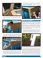
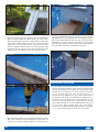
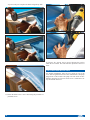
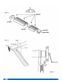
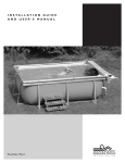
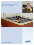
I N S TA L L AT I O N G U I D E
AND USER’S MANUAL
Fa s t l a n e Po o l
Installation Instruction Booklet Information
Endless Pools, Inc. provides for every aspect of a Fastlane Pool project. This manual assists in the installation process,
as well as the general maintenance of your Fastlane Pool.
Additional available resources including the Planning Guide and selected Supplemental Guides are available to you. These
documents are available online at www.myendlesspool.com/downloads.html. In addition, we encourage installers to call
our Customer Service Department at (800) 910-2714 before beginning installation to register their projects and sign up for
weekend technical support.
Please be advised that gloves and safety goggles should be worn during the installation of a Fastlane Pool.
Please take into consideration the following before proceeding:
If you have purchased the Optional Heater/Controller package, that will require a 3-wire (w/ neutral) 220v, 30 amp,
GFCI power supply.
If you have purchased the standard package, than no neutral is required and the wire can be left unused.
Installation Instructions Table of Contents
Receiving the Fastlane Pool. . . . . . . . . . . . . . . . . . . . . . . . . 2
Pool Positioning . . . . . . . . . . . . . . . . . . . . . . . . . . . . . . . . . . 2
Ground Preparation . . . . . . . . . . . . . . . . . . . . . . . . . . . . . . . 3
Pool Assembly . . . . . . . . . . . . . . . . . . . . . . . . . . . . . . . . . . . 3
Fastlane Swim Unit Assembly . . . . . . . . . . . . . . . . . . . . . . . 5
Water Quality System . . . . . . . . . . . . . . . . . . . . . . . . . . . . . 7
Skimmer Assembly . . . . . . . . . . . . . . . . . . . . . . . . . . . . . . . 8
Connecting Skimmer/Suction Wall Fitting . . . . . . . . . . . . . 8
Connecting Return Wall Fitting . . . . . . . . . . . . . . . . . . . . . . 8
Drainage . . . . . . . . . . . . . . . . . . . . . . . . . . . . . . . . . . . . . . . . 9
Fastlane Hydraulic Power Unit Assembly . . . . . . . . . . . . . . 9
Bonding and Grounding. . . . . . . . . . . . . . . . . . . . . . . . . . . . 9
Hydraulic Fluid . . . . . . . . . . . . . . . . . . . . . . . . . . . . . . . . . . 9
Assembling the Water Quality System . . . . . . . . . . . . . . . 10
Fastlane Equipment Hutch Assembly . . . . . . . . . . . . . . . . 11
1
Electrical Requirements 60Hz . . . . . . . . . . . . . . . . . . . . . . 12
Electrical Requirements 50Hz . . . . . . . . . . . . . . . . . . . . . . 12
Heater Controller . . . . . . . . . . . . . . . . . . . . . . . . . . . . . . . . 13
Using the Fastlane Swim Unit . . . . . . . . . . . . . . . . . . . . . . 16
Installing the an Antenna Extension . . . . . . . . . . . . . . . . . 16
Caring for the Fastlane Pool . . . . . . . . . . . . . . . . . . . . . . . 16
Placarding the Fastlane Pool . . . . . . . . . . . . . . . . . . . . . . . 17
Retractable Security Cover Installation . . . . . . . . . . . . . . . 18
Installing the Ladder . . . . . . . . . . . . . . . . . . . . . . . . . . . . . 22
Installing the Cover . . . . . . . . . . . . . . . . . . . . . . . . . . . . . . 23
Outdoor Installations . . . . . . . . . . . . . . . . . . . . . . . . . . . . . 27
Wiring Schematic 60Hz . . . . . . . . . . . . . . . . . . . . . . . . . . . 30
Wiring Schematic 50Hz . . . . . . . . . . . . . . . . . . . . . . . . . . . 31
Fastlane Pool Warrantee. . . . . . . . . . . . . . . . . . . . . . . . . . . 32
RECEIVING THE FASTLANE POOL
The Fastlane Pool is shipped via UPS and contains at least
16 packages:
Box 1: Fastlane Pool Power Unit
Box 2: Biodegradable Vegetable Fluid
Box 3: Fastlane Pool Swim Unit Housing
Box 4: Fastlane Pool Swim Unit Accessories
Qty 2 - Hydraulic Hose Protective Channels
Qty 1 - Acrylic Top for Swim Unit
Qty 1 - Acrylic Hanging Bracket
Qty 1 - Top Bumper
Qty 1 - Lower Standoff
Qty 1 - Owner’s Manual Kit (Padded Envelope)
Qty 1 - Owner’s Manual
Qty 2 - Hydraulic Adapters (8 Female JIC x 6 Male JIC)
Qty 1 - Fastlane Pool Bonding Kit
Qty 36 - 3/4” 10-32 Machine Screws
Qty 10 - 1” 10-32 Machine Screws
Qty 4 - Rubber Grommets
Box 5: Fastlane Pool Swim Unit Base
Box 6: Fastlane Pool Liner Box (Only for a 9x13 Pool)
Qty 1 - Pool Liner
Qty 2 - Vertical Struts
Qty 4 - Top Corner Tubes
Qty 4 - Bottom Corner Tubes
Box 6a (Only for a 9x17 Pool)
Qty 1 - Pool Liner
Qty 4 - Vertical Struts
Qty 4 - Top Corner Tubes
Qty 4 - Lower Corner Tubes
Qty 2 - 120cm Top Straight Tubes
Qty 2 - 120cm Bottom Tubes
Box 7: Fastlane Pool Strut Box
Qty 8 - Vertical Struts
Box 8: Fastlane Pool Tube Box
Qty 2 - 120cm Top Straight Tubes
Qty 2 - 60cm Top Straight Tubes
Qty 3 - 120cm Straight Bottom Tubes
Box 9: Fastlane Pool Tube Box
Qty 2 - 120cm Top Straight Tubes
Qty 2 - 60cm Top Straight Tubes
Qty 3 - 120cm Straight Bottom Tubes
Box 10: Fastlane Pool Water Quality System
Qty 1 - 50sq ft Skim Filter
Qty 1 - Circulating Pump
Qty1 - Plumbing Parts bag
Qty 2 - Thru-wall Fittings
Qty 2 - MPT x Slip 90º Street Elbows
Qty 2 - Slip x Slip Unions
Qty 2 - Slip x Slip Ball Valves
Qty 2 - Pump Unions with O-Rings
Qty 1 - Male Slip x Female Slip 90º Street Elbow
Qty 1 - MPT x Insert Adapter
Qty 1 - MPT x Insert 90º Elbow
Qty 2 - Plastic Hose Clamps
Qty 2 - Threaded Plug with O-Ring
Qty 1 - Eyeball Fitting
Qty 1 - 4oz PVC Cleaner
Qty 1 - 4oz PVC Cement
Qty 1 - Teflon Tape
Qty 1 - Liquid Tite Electrical Fitting
Qty1 - Fastlane Pool Start Up Bag
Qty 1 - Container of Test Strips
Qty 1 - Water Clarifier
Qty 1 - pH Increaser
Qty 1 - pH Decreaser
Qty 1 - Vinyl Cleaner
Qty 1 - Bag of Shock
Qty 1 - Nature 2 Purifying Cartridge
Box 11: Fastlane Pool Skim Filter Housing Assembl
Qty 1 - Skim Filter Housing
Qty 2 - Large Bent Tabs
Qty 2 - Small Bent Tabs
Qty 10 - 1/2” 10-32 Stainless Steel Machine Screws
Qty 5 - 1” Self Tapping Stainless Steel Screws
Qty 1 - 11/64” Drill Bit
Qty 1 - 3’ Length of Suction Hose
Box 12: Fastlane Pool Equipment Hutch
Qty 1 - Equipment Hutch
Qty 1 - Equipment Mounting Board
Qty 1 - Pump Mounting Clamp
Box 13: 50’ Roll of Flexible PVC
Box 14: Fastlane Pool Ladder
Box 15: Solar cover
Box 16: Optional Heater Controller
Qty1 - Heater Controller
Qty1 - Keypad for Heater Controller
Qty2 - Heater Tail Piece
Qty2 - Heater Tail Piece T Gaskets
Qty1 - Slip x Slip 90º Elbow
Qty1 - Male Slip x Female Slip 90º Street Elbow
Qty1 - 6-1/2” PVC Nipple
Qty1 - 4-1/4” PVC Nipple
Qty1 - Heater Controller Mounting Clamp
Qty4 - 3/4” 10-32 Machine Screw
Qty4 - 10-32 KEP Nut
POOL POSITIONING
To ensure ideal operation of the Fastlane Pool, consider the following steps when selecting a location for the pool.
• Look for an area that receives maximum sunlight for increased
heat and extended use.
• Find a location with minimal wind exposure to minimize
heat loss.
• Be aware of the amount of trees and shrubbery around the pool
to limit the amount of debris that may accumulate in
the pool.
• Select a location with accessibility to water and
electric sources.
• Consider privacy when selecting a location.
2
DIAGRAM #1: SUPPORTING LEGS / STRUTS
GROUND PREPARATION
The surface the Fastlane Pool is to be assembled on must be firm
and level. The Fastlane Pool must be installed as level as possible, within 2"- 3" of level (from the highest point to the lowest
point of the pool). If the pool will be assembled on a sloping surface, be sure to install the skimmer on the lower side to ensure that
it will not suck air into the pump. If the ground is not level and it
is desired to make a more level surface, take the earth from the
high area of the uneven surface; do not add earth to the low area
of the surface. Once the surface is level, clear any debris or sharp
objects that may be uncomfortable to walk on or could become a
puncture hazard for the liner. Foam flooring may be added under
the liner for additional comfort.
The pool is comprised of various parts. Therefore, before proceeding with installation, ensure that all necessary parts for the
pool are present and group like parts together.
Part Description
(A) Liner
(B) Top 130cm straight tubes (wider)
(C) Top 60cm straight tubes (wider)
(D) Top corner tubes (wider)
(E) Bottom corner tubes (thinner)
(F) Straight bottom tubes (thinner)
(G) Struts
Quantity
1
6 (8 for Longer Pool)
4
4
4
6 (8 for Longer Pools)
10 (12 for Longer Pools)
POOL ASSEMBLY
1. Unfold and spread out liner (Part A) on the prepared area.
NOTE: Keep in mind the desired “swim direction” when
positioning the liner, because when the Fastlane Pool is
fully assembled, the swim direction will be headed towards
the end of the pool that has the pre-cut holes. These holes are
for the water quality thru-wall fittings and hydraulic hoses.
2. Align the struts (Part G) with the prepared cut outs at top
of liner.
A
G
B
D
F
E
C
The supporting legs, or struts (Part G), support much of the weight
of the Fastlane Pool and may need additional support in “soft
ground” installations, or in areas that may experience excess
ground water. A 2"x 8" x 22" piece of lumber installed under each
strut’s base and leveled with the ground is very effective. Make
sure the entire base of each strut is on the 2" x 8" lumber as any
over-hang may result in bending of the strut. A concrete slab of
the similar dimensions may be used as well. Please note that any
support(s) added under the pool structure must be recessed so that
the top of the support is level with the ground surface. Lifting the
struts or frame in any manner may cause excessive stress on the
liner and frame, and may void the Fastlane Pool warranty. (Refer
to Diagram #1: Supporting Legs / Struts.)
3
3. Connect bottom tubes (Part F) to struts (Part G) one at a time to
make the four sides of the pool. Connect corner tubes (Part E) to
the open ends of both struts to finish each of the four corners.
Longer (9' x 17') Fastlane Pool
4. Connect the top tubes (Parts B and C) together. NOTE: The
shorter tube (Part C) is always the last tube on the right
when facing the pool wall. (Refer to Diagram #2: Wider
Straight Tube Layout.)
5. Feed the connected top tubes (Parts B and C) into the
corresponding sleeves of the liner. Be sure to align the top tube
slots with the matching cutouts in the liner, and then insert the
corresponding struts (Part G) into the top tube slots.
DIAGRAM #2:WIDER STRAIGHT TUBE LAYOUT
Standard (9' x 13') Fastlane Pool
4
FASTLANE SWIM UNIT ASSEMBLY
1. Verify that all items have arrived. NOTE: If using a power
drill, do NOT over tighten the screws, as this will strip the
thread in the PVC of the Fastlane Swim Unit.
2. Carefully unpack the Swim Unit Housing, Swim Unit Base and
its components from box numbers 10, 11 and 13 (Refer to section titled, RECEIVING THE FASTLANE POOL). Remove
and verify all hardware kits from inside. Close the boxes and
flip them upside down on the ground to use as a workbench or
collapse the boxes and use as a smooth surface to protect the
components from scratching.
3. Turn the Swim Unit Housing upside down on the box or another smooth surface. Remove the block of wood by
removing the screws that attach the wood to the Swim Unit
Housing. The wood is for packaging purposes only and may be
discarded.
6. Insert and connect the top corner tubes (Part D). It may be
helpful to insert both ends of corner tube into the corresponding
liner sleeves, and then pull back on the corner tube to connect
one end at a time to the top rails (Parts B and C).
4. Remove the screws on the two sides and the front of the Swim
Unit Housing that secure the throat. Set the throat and the
screws aside to be used in Step 13.
5. Set the Swim Unit Base on the cardboard box with the cylinder
facing up. Lay the hydraulic hoses that come pre-attached to
the Swim Unit Base to each side so that they are out of the way.
Flip the Swim Unit Housing over and set on top of the Swim
Unit Base. Secure the Swim Unit Base to the Swim Unit
Housing by using six of the 1" stainless steel screws provided
(three screws on each side). NOTE: Do not over-tighten.
7. Ensure that all tubes around the perimeter are completely nested in one another and properly connected, and that no parts of
the frame are racked or crooked.
8. Slowly begin to fill the pool with water until the bottom of the
liner is almost taught. Remove any wrinkles in the pool liner at
this time, as it will be difficult to do so once there are more than
just a few inches of water in the pool.
9. To prevent leaking issues, it is very important to plumb and
plug both through walls before the water level reaches the two
pre-cut holes in the liner. For more information, refer to the
section in this Owners’ Manual titled, WATER QUALITY
SYSTEM, SKIMMER & THRU-WALL FITTINGS.
10. Once these holes have been plugged, assemble the Fastlane
Swim Unit.
5
6. Carefully feed the bond wire that is attached to the Swim Unit
Base up behind the horizontal honeycomb grill located in the
bottom of the Swim Unit Housing and up through the turning
vanes. Install the grab rail using six 3/4" stainless steel screws
and the six 10-32 stainless steel lock nuts provided. Secure the
bond wire that has been fed up through the turning vanes under
one of the six screws. Secure the other bond wire that has been
pre-installed in the Swim Unit Housing under a second screw in
the grab rail. NOTE: Do not over-tighten.
7. Run the hydraulic hose up the back of the Swim Unit Housing
so that the PVC hydraulic hose protective channel will cover the
hose. Firmly secure but do NOT over tighten the eight stainless screws per channel. Repeat for the second hose.
10. Attach the top bumper piece (length of PVC pipe) to the Swim
Unit Housing through the unused screw holes (top holes from
Step 9) in the acrylic hanging bracket using two of the ten 1”
stainless steel screws. NOTE: Do not over-tighten.
8. Once both protective channels are attached, pull the two
hydraulic hoses tight and secure them to the top of the Swim
Unit Housing using the green hose clamps provided. To accomplish this, unscrew the green hose clamps, insert
the hoses, and re-screw the clamps snugly into the top of
the Swim Unit Housing. Feed the bond wire (from Step 6)
to the back of the Swim Unit Housing along one of the
hydraulic hoses.
11. Attach the lower extension bumper to the rear of the Swim
Unit Base using two 3/4" stainless steel screws. NOTE: Do
not over-tighten.
9. Attach the acrylic hanging bracket to the back of the Swim Unit
Housing with four of the 3/4" stainless steel screws. NOTE: Do
not over-tighten. Leave the two top screw holes unused.
12. Attach the wheels to the Swim Unit base. Slide the axle through
the two holes that are marked in yellow on the intake grill in the
Swim Unit base. These holes have been widened to allow the
axle to pass through freely. There are a total of four large and
two small washers used in the wheel assembly. Be sure that two
large washers are located between each wheel and the intake
grill. Secure the wheels to the axle with one smaller washer
between the screw and the wheel on both sides.
6
13. Re-install the throat that was removed previously in Step 4.
14. Place the Swim Unit on the ground and roll it close to the
Fastlane Pool location for installation. Be careful not to tip
over the Swim Unit, as it is front-heavy.
15. Once the pool is nearly full and the liner is taught and wrinkle-free, carefully lift the assembled Fastlane Swim Unit into
the pool at the skimmer end. Lower and position the Swim
Unit so that the acrylic hanger “clips” on to the top straight
tube (Part B) as shown in Step 18. The Swim Unit should be
centered along the end of the pool.
16. The hydraulic hoses can be simply left hanging over the top of
the pool wall to run back to the Power Unit, or they can be fed
through the pool wall as described in Steps 17 & 18. Attach
the bond wire to the nearest supporting strut (Part G) using the
provided self-drilling / self-tapping screw to bond the Swim
Unit to the pool’s structural frame.
19. Install the top cover of the Swim Unit Housing using six 3/4”
stainless steel screws (three screws on each side).
20. Run the hydraulic hoses back to the Hydraulic Power Unit.
Using the provided bonding lug and self-drilling / self-tapping
screw, fasten the bonding lug to the bottom of the same strut
used in Step 16 (when the Fastlane Swim Unit was bonded to
the pool’s structural frame). To bond the Fastlane Swim Unit
and Fastlane Pool structure to the rest of the pool equipment,
run a #8 AWG bare copper wire from the bonding lug (that
was just attached) to the rest of the Water Quality System
equipment and Hydraulic Power Unit. Always be sure to verify any additional bonding requirements that may be dictated
by local codes and ordinances.
WATER QUALITY SYSTEM, SKIMMER
& THRU-WALL FITTINGS
(NOTE: Steps 17 & 18 are optional, skip to Step 19 if choosing
not to feed hoses through the pool wall)
Plumbing and Start-up Kit (See section titled, RECEIVING THE
FASTLANE POOL, Box #10)
17. If a more finished look is desired, four rubber grommets have
been provided to fit into holes that can be cut into the top
white section of the liner. Once the Fastlane Swim Unit has
been properly placed in the pool and is centered along the
width of the pool, locate the holes through which the hydraulic
lines will run. Using a permanent marker (while outside the
pool and along the exposed side of the acrylic hanger), dot the
liner with two marks, each being 1-1/2” away from the vertical edges of the hanger (away from center) and 3” down from
the top of the pool. Place a rubber grommet over the marks so
that they are centered in the grommet openings. Trace the
INSIDE of the grommets onto the liner. Using a utility knife
with a sharp blade, SLOWLY and CAREFULLY cut out the
traced circles. Refer to photo in Step 18 to verify hole location before cutting. NOTE: Cutting small curves or a circle
with a utility knife can be difficult. It may be best to work in
many small straight cuts for accuracy.
Qty 1
4oz Container of PVC Cleaner
Qty 1
4oz Container of PVC Cement
Qty 2
Pump Union with 1-1/2" Adapter with O-Ring
Qty 1
Male Slip x Female Slip 1-1/2" 90º Street Elbow
Qty 2
Female Slip x Female Slip Ball Valve
Qty 2
Female Slip x Female Slip Union
Qty 2
Male Pipe Thread x Female Slip 90º Street Elbow
Qty 1
1-1/2" Eyeball Fitting
Qty 2
1-1/2" Threaded Plugs with O-Ring
Qty 1
1-1/2" Male Pipe Thread x Insert 90º Elbow
Qty 1
1-1/2" Male Pipe Thread x Insert Adapter
18. Push the grommets into the holes so that the fabric edges tuck
inside the grooves of the grommets. Repeat this process again
for two more holes inside the pool. NOTE: When complete,
the hydraulic hoses and bonding wire will be passing through
two layers of fabric. It is important to feed the hydraulic hoses
and bonding wire through both grommets, starting from inside
the pool and then feeding them through the outer layer of fabric as shown in the photo below.
Qty 1
3' Length of Flexible Hose
Qty 2
1-1/2" PVC Thru-Wall Fitting Female Thread (inside) x
Female Thread (outside)
7
Additional Tools Required
• Tape measure
• Hack saw
SKIMMER ASSEMBLY
1. Align the skimmer opening with the opening in the housing.
Use the hardware provided with the skimmer to attach the
skimmer to the housing. Make sure to use the skimmer faceplate when attaching the skimmer.
5. Once the skimmer assembly is complete, place it inside the pool
in the same corner as the lower thru-wall fitting. (front right)
6. Use the provided drill bit and self-tapping screws to attach the
skimmer assembly to the top tube of the pool. Position the holes
in the larger tab with the center of the tube. Drill through the
liner and tube with the drill bit. and then secure the assembly to
the top tubes with the four self tapping screws.
CONNECTING SKIMMER /
SUCTION WALL FITTING
(Refer to Diagram #3: Skimmer / Suction Thru-Wall Diagram)
• Push fitting (#4) through the wall of the pool from the inside.
MAKE SURE TO USE A GASKET (#5) on both sides of the
wall of the pool. Place the cork ring next to the gasket outside
the pool and secure the wall-fitting nut (#7) to (#4) now sticking
through the pool wall. Tighten with a large pair of channel locks.
Make sure the nut is very snug but do not over-tighten, as this
may crack the fitting.
2. Attach the skimmer body to the skimmer housing. Align the 2
smaller tabs to the underside of the holes in the top of the housing. The long face of the small tab should be aligned with the
circular opening in the housing. Use the provided machine
screw to attach the small tab to the housing.
• Thread the union and insert adaptor (#1) into the bottom of the
skimmer. NOTE: No glue or tape is necessary to complete this
step.
3. Once the skimmer is attached to the housing through the opening, use the provided drill bit to drill a hole into the skimmer
through the hole in the small tab. Thread in a short machine
screw into each hole, securing the skimmer to the small tabs.
• Wrap a small amount of Teflon tape around the end of the adaptor.
• Inside the pool, thread the insert elbow (#3) into the thru-wall (#4).
• Press the flexible hose (#2) onto each of these fittings. Use the
provided plastic hose clamps to attach.
• Outside the pool, thread in the male portion of the street ell (#8)
into the tailpiece of the thru-wall fitting (#4).
• When the water quality system equipment needs maintenance,
the insert elbow fitting (#3) should be removed and the provided plug should be threaded into the thru-wall fitting (#4) to prevent the pool from draining.
DIAGRAM #3: SKIMMER / SUCTION THRU-WALL DIAGRAM
Pool Wall
Skimmer
Do Not
Glue
6
4. Place the larger tab’s smaller face onto the underside of the outside of the housing so that the pre-drilled holes are aligned. Use
the provided sheet metal screws to attach the larger tabs to the
housing.
1
3
8
Glue Pipe
From PUMP
7
5
5
4
Thru-Wall
2
CONNECTING RETURN WALL FITTING
(Refer to Diagram #4: Return Wall Fitting Diagram)
• Push fitting (#8) through the wall of the pool from the inside.
MAKE SURE TO USE A GASKET (#9) on both sides of the
wall of the pool. Place the cork ring next to the gasket outside
the pool and secure the wall-fitting nut (#10) to (#8) now sticking through the pool wall. Tighten with a large pair of channel
locks. Make sure the nut is very snug but do not over-tighten, as
this may crack the fitting.
8
• Outside the pool, thread in the male portion of the street elbow
(#6) into the tailpiece of the thru-wall fitting (#8).
• From inside the pool, thread the eyeball fitting into the thru-wall
fitting (#8). Point the eyeball towards the bottom of the pool for
optimal water circulation in the Fastlane Pool.
• When the water quality system equipment needs maintenance,
the eyeball fitting should be removed and the provided plug
should be threaded into the thru-wall fitting (#8) to prevent the
pool from draining.
DIAGRAM #4: RETURN WALL FITTING DIAGRAM
Pool Wall
2
6
Glue Pipe
From PUMP
10
9
9
8
The power unit controller comes equipped with an automatic timer
shutting off the system 30 minutes after receiving its last command.
Because the controller "remembers" the last speed at which is
turned off, it will return to that same pace when it is turned back on.
BONDING AND GROUNDING
All of the electrical equipment that we supply is UL or CSA approved
and must be installed in accordance with local electric codes by a
licensed local electrician. Bonding and Grounding is an important
part of that process. All electrical components have bonding lugs and
should be bonded together and to the steel pool panels. A bonding
conductor shall be solid copper not smaller than 8 AWG and may be
insulated, covered or bare. If new construction is involved where reinforcing rods are installed in the concrete under or adjacent to the pool
this should be included in the bonding circuit. Each of the pieces of
equipment should be separately grounded.
A #8AWG bare copper wire is required for all bonding connections.
Connect this wire to your power unit and run it, with your hydraulic
hose and whip, to the front of the pool. Inside the bonding kit there
will be a machine screw and nut, a bonding lug, and a drill bit. Feed
the bonding wire through the bonding lug vertical strut at the front
of the pool. Connect the Fastlane stainless steel bond wire and the
bare copper wire to this bonding lug.
Thru-Wall
DRAINAGE
Drainage needs to be provided around the pool and near the water
quality equipment. It is important to be prepared in the unlikely
event of a leak. If operating the Fastlane Pool indoors, it is ideal to
install floor drains in the area around the pool’s perimeter, but not
directly under the pool. It is worth the time and effort now to install
a drainage system rather than be unprepared in the event of a mishap.
HYDRAULIC FLUID
Fill the reservoir on the Power Unit no more than 2" from the top of
the reservoir. Endless Pools, Inc. supplies a special non-petroleum
fluid created for this application and this equipment. Do not use a
substitute hydraulic fluid. Extra hydraulic fluid is provided for longer
hose runs. Any excess fluid should be retained for future use.
Low
Pressure
Fitting
FASTLANE HYDRAULIC POWER
UNIT ASSEMBLY
The power unit should placed on flat and level surface. Whether
placed indoors or outdoors, this is an air-cooled unit and must have
ample ventilation. Therefore, a minimum of 12" of air spaced must
be provided on all sides of the power unit. In addition, the power
unit needs to be check periodically for maintenance and should be
accessible.
The power unit is heavy, care should be taken when placing the power unit.
Once the power unit is in place, connect the run hoses. The low
pressure hose, which will have red tape, gets connected to the connection on the black fill cap. The high pressure hose gets connected
to the fitting on the high pressure manifold.
Make sure that the power is turned off to the power unit. Remove
the fill black fill cap and remove the oil filter by lifting it out of fill
opening. Use the provided paper funnels and fill the reservoir to
with in 2" of the top. Once filled, replace the oil filter and ensure
that it is seated properly before putting the fill cap back on. If you
have selected a longer run hose, we have provided extra fluid. In
this case, turn the unit on and let it run for one minute to fill the run
hoses. Turn the power off, remove the fill cap and oil filter, and add
fluid as needed. Again, you want to fill the reservoir to within 2" of
the top.
9
Fill Cap
High
Pressure
Fitting
Make sure that all hydraulic connections are tight, then press the ON
button on the remote to turn on the Power Unit. Run for a minute or
two then check for hydraulic leaks at the Power Unit and the pool and
tighten if necessary. By pressing the OFF button on the remote you
can turn off the Power Unit. Make sure you can do this.
ASSEMBLING THE WATER QUALITY SYSTEM
WITHOUT HEATER CONTROLLER
Loosely attach the circulating pump to the power unit. The pump
will be attached to the handle of the power unit on the same side
as the hydraulic connections. Place the circulating pump on to the
power unit so that the suction of the circulating pump is facing
out. Place the pump foot clamp on the underside of the power unit
handle, aligning the holes in the pump foot clamp to the holes in
the pump foot. Use the provided screws to clamp the pump on the
power unit handle.
Attach the pump union nuts to both fittings of the pump. Make
sure that the o-rings are in place before attaching the union fittings. Glue a male slip x female slip street elbow into the pressure
fitting of the pump so that it is facing away from the power unit.
Cut two 2-1/2” lengths of flexible PVC off of the 50’ roll of flexible PVC that was provided. Glue one of these lengths into the
union fitting connected to the suction side of the pump. Glue the
other length of 2-1/2” PVC into the elbow that is connected to the
pressure union. Next glue a slip x slip ball valve onto each of the
2-1/2” lengths of flexible PVC. Finally, cut the 50’ length down
to the appropriate lengths to connect the suction side of the pump
to the skimmer thru-wall assembly and connect the pressure side
of the pump to the return thru-wall assembly.
Suction
Pressure
Then place the heater controller-mounting clamp onto the mounting board so that they are aligned with the holes closest to the
power unit. The tabs of the mounting clamp should be facing away
from the power unit. There should also be a gap between the tab
and the spacer. Use the provided hardware to attach the mounting
clamp to the mounting board. DO NOT install screws into the
front holes at this time.
Now slide the heater controller into position, so that the plug-in
ports are facing away from the power unit and the feet of the
heater controller are seated firmly under the mounting clamp.
Once the heater controller is in place, use the provided nut and
machine screws to attach the Heater/Controller to the mounting
board.
ASSEMBLING THE WATER QUALITY SYSTEM
WITH HEATER CONTROLLER
Note: Additional PVC fittings can be found in the Heater
Controller box. Loosely attach the circulating pump to the power
unit. The pump will be attached to the handle of the power unit
on the same side as the hydraulic connections. Place the circulating pump onto the power unit so that the suction of the circulating
pump is facing out. Place the pump foot clamp onto the underside
of the power unit handle, aligning the holes in the pump foot
clamp to holes in the pump foot. Use the provided screws to
clamp the pump to the power unit handle.
Pre-cut lengths of PVC have been provided. Apply PVC cleaner
to both faces of the joint prior to gluing for every glue joint. Take
the 6-1/2” long piece of pipe and glue the female end of a male
slip x female slip elbow (street elbow) onto one end and glue a
pump union onto the other. Make sure that the union nut is in place
prior to gluing. Finally, glue a heater controller union half onto
the male end of the street elbow. Once this assembly has been
glued together, connect the pump to the heater controller. Make
sure that there is an o-ring between the pump union and the pump
discharge and there is a T-Gasket between the heater controller
union nut and the union half.
Next remove the two reservoir mounting bolts on the side opposite the power unit controller. Align the holes in the heater controller mounting board with holes in the power unit that were just
removed. Replace the bolts and tighten securely.
10
FASTLANE POOL EQUIPMENT
HUTCH ASSEMBLY
1. Begin by attaching the PVC support (B) to the underside of the
lid (A). Two supports have been provided and are labeled. One
support will be for a 60hz power supply and one support will be
for a 50hz power supply. Choose the support that is appropriate
for your application. If you are unsure which power supply you
have, refer to the specification plate on the motor.
Next, take the 4-1/4” long piece and glue a slip x slip 90º elbow
onto one end. At the other end of this pipe another street elbow
will be glued on, but the 2 faces of the elbows must be aligned.
This can be accomplished by placing both faces of the elbows
onto level ground immediately after the second elbow has been
glued on. This will force the elbows to be facing the same way.
Now take this assembly and glue a heater controller union half
onto the male end of the street elbow. Connect the union half to
the heater controller so that the slip x slip elbow is down and facing the under the mounting board.
2. Next, assemble the four vertical panels. The textured side of the
panels will be facing out and each panel will be labeled on the
inside face. Panels 1 and 2 have no tabs on the vertical edges
while panels 3 and 4 do. Position the panels so that 1 is opposite 2 and 3 is opposite 4. Align the holes in panels 1 and 2 with
the tabs of 3 and 4. Use the shorter screws to attach the 4 panels together.
3. The underside of the lid will have 1-4 engraved on each side.
Line up the numbers on the underside of the lid with the corresponding vertical panel. Use the longer screws to attach the lid
to the vertical face. Make sure that there is a cylindrical space
between the lid and the vertical face at each screw.
4. Remove the mounting bracket and adhesive protective film of
the heater controller keypad. Feed the keypad cord into the oval
hole in panel 4. Press the keypad firmly against the panel. Feed
the mounting bracket back over the keypad cord and tighten it
against panel 4.
5. Once the Water Quality System is fully assembled, place the
weather guard over the entire power unit so that the opening in
panel 2 is seated around the power unit controller.
6. Align the 3 holes in the bottom of panel 1 with the holes in the
water quality base. Use the short screws to attach the weather
guard to the base.
4
2
A
1
Cut a length of flex PVC from the roll so that when glued into the
slip x slip elbow the opposite end of the pipe is just beyond the
base. Then glue a valve onto the end of that pipe. Finally, use the
flexible pipe to connect the valve to the return fitting union on the
pool.
Cut a 2-1/2” length of flexible PVC and glue that into the suction
fitting on the pump. Glue a valve onto that short piece of pipe.
Then glue a length of PVC between that valve and the suction fitting on the pool.
3
B
Panel 2
Panel 4
Panel 1
Panel 3
11
ELECTRICAL REQUIREMENTS
AND CONNECTIONS (60Hz)
2. Connect the whip, provided with the heater controller, between
the unused knockout in the power unit controller and the
knockout in the top left of the heater controller.
Consider the electrical requirements for the specific installation
before locating the Water Quality System and gluing the plumbing parts. Different option packages require different plumbing
and electrical configurations.
3. Inside the heater controller, connect the black wire to terminal
L1, connect the red wire to terminal L2, connect the white wire
to terminal N, and connect the green to terminal B. All four
terminals will be color-coded.
Standard Fastlane Pool package with no heater
A licensed electrician should make all electrical connections. The
standard package will require a two-wire (plus ground) 220 volt
30 amp GFCI Power Supply. The power unit controller may
have to be attached to the power unit. If not done so already, connect the power unit as directed. There are two electrical whips
attached to the controller. The shorter one needs to be connected
to the power unit motor. The longer whip is going to be prewired into the LINE side of the contractor in the controller, which
will then need to be connected to the incoming power supply. The
white wire in the long whip will be unused in this application.
4. Inside the power unit controller, connect the four wires coming
from the heater controller to the contactor as follows: connect
the black wire to terminal R2 (top left), connect the red wire to
terminal R3 (bottom right), connect the green wire to the
ground bus bar at the bottom of the control box, and connect
the white wire to other white wire that is coming from the
incoming power supply.
Please refer to the following step-by-step instruction for supplying power to the circulating pump.
1. Cut the plug of the cord and strip back and expose the 3 wires.
2. Remove one of the unused 1/2” knockouts in the bottom of the
Controller Box that is attached to the Hydraulic Power Unit.
Slide the liquid tight fitting over the cord of the WQS pump
with the compression nut end first. With the liquid tight fitting
still loose on the cord, push the threaded end of the fitting into
that hole in the Controller Box and determine the length of
cord that will need to feed into the box.
3. When the correct length is determined, tighten the compression
nut on the cord. Then feed the locknut over the cord and thread
the locknut onto the fitting to securely affix it to the Controller
Box.
4. On the contactor located inside the Controller Box, attach the
WQS pump’s cord to the LOAD side of the contactor. The
black wire goes to terminal R1, the white wire goes to terminal
R3, and the green wire goes to the ground bus bar on the bottom of the Controller Box.
Fastlane Pool package w/ Optional Heater Controller
A licensed electrician should make all electrical connections.
This option will require a three-wire (plus ground) 220 volt 30
amp GFCI Power Supply. The power unit controller may have to
be attached to the power unit. If not done so already, connect the
power unit as directed. There are two electrical whips attached to
the controller. The shorter one needs to be connected to the
power unit motor. The longer whip is going to be pre-wired into
the LINE side of the contractor in the controller, which will then
need to be connected to the incoming power supply. The white
wire will need to be connected to the load neutral of the 30amp
GFCI breaker (the neutral pigtail needs to be connected to the
neutral bus bar inside your breaker panel). A third electrical whip
will be provided with the heater controller. That will be wired
into the contactor as well. The WQS pump and heater controller
will only run when the swim current is not in use, but the keypad
will always have power.
Please refer to the following step-by-step instruction for supplying power to the heater controller:
1. Power is supplied to the system by connecting the existing
whip on the power unit control box to the shut off installed by
your electrician.
5. Plug the circulating pump into the CP port on the
heater controller.
Wiring diagrams are available at the back of this book.
Fastlane Pool Package with optional 55,000 BTU Gas or
Propane Heaters
A licensed electrician should make all electrical connections. The
standard package will require a two-wire (plus ground) 220 volt
30 amp GFCI Power Supply. The power unit controller may
have to be attached to the power unit. If not done so already, connect the power unit as directed. There are two electrical whips
attached to the controller. The shorter one needs to be connected
to the power unit motor. The longer whip is going to be pre-wired
into the LINE side of the contractor in the controller, which will
then need to be connected to the incoming power supply. The
white wire in the long whip will be unused in this application.
Power will be supplied for both the circulating pump and the
heater from the LOAD side of the contactor in the power unit
controller. Endless Pools does not provide an electrical connection between the power unit and the heater; these need to be provided locally. In this application, the heater and circulating pump
will be shut off when the swim current is on.
Please refer to the following step-by-step instruction for supplying power to the heater and circulating pump:
1. A two-wire 10AWG (plus ground) connection will need to be
made between the power unit controller and the heater.
2. Inside the power unit controller, connect the one wire to terminal R1, connect the other wire to terminal R3, and connect the
ground wire to the bus bar at the bottom of the controller.
3. The other end of this connection must terminate inside a junction box that is attached to the electrical knockout of the heater.
4. Make sure that the heater’s transformer is wired for 220 volts.
See the heater’s owner’s manual for more information.
5. Cut off the plug off of the circulating pump cord, expose the
three wires inside and strip back each individual wire. Have
this cord terminate inside the junction box that was connected
to the heater in step 3.
6. Under one wire nut, connect all 3 ground wires (green) from
the heater, the pump, and the connection from the power unit
controller.
7. Under one wire nut, connect one leg of the incoming power
to one of the wires from the heater and one of the wires from
the pump. Under another wire nut connect the three remaining wires.
12
ELECTRICAL REQUIREMENTS (50Hz)
Fastlane Pool without Heater Wiring Instructions
A licensed electrician should make all electrical connections. The
standard package will require a two-wire (plus ground) 220 volt 30
amp RCD Power Supply. The power unit controller may have to be
attached to the power unit. If not done so already, connect the power
unit as directed. There are two electrical whips attached to the controller. The shorter one needs to be connected to the power unit
motor. The longer whip is going to be pre-wired into the LINE side
of the contractor in the controller, which will then need to be connected to the incoming power supply. The white wire in the long
whip will be unused in this application.
HEATER CONTROLLER
Connections simply snap into appropriate color coded receptacles.
Please refer to the following step-by-step instruction for supplying
power to the circulating pump.
1. Cut the plug of the cord and strip back and expose the 3 wires.
2. Remove one of the unused 1/2” knockouts in the bottom of the
Controller Box that is attached to the Hydraulic Power Unit.
Slide the liquid tight fitting over the cord of the WQS pump with
the compression nut end first. With the liquid tight fitting still
loose on the cord, push the threaded end of the fitting into that
hole in the Controller Box and determine the length of cord that
will need to feed into the box.
3. When the correct length is determined, tighten the compression
nut on the cord. Then feed the locknut over the cord and thread
the locknut onto the fitting to securely affix it to the Controller
Box.
4. On the contactor located inside the Controller Box, attach the
WQS pump’s cord to the LOAD side of the contactor. The black
wire goes to terminal R1, the white wire goes to terminal R3, and
the green wire goes to the ground bus bar on the bottom of the
Controller Box.
Fastlane Pool with Heater Wiring Instructions
Two 220v 30amp RCD rated circuits are required when the optional electric heater has been selected. A minimum of 10AWG wire
should be used for all field wiring. All connections should be made
by a licensed electrician.
Input wiring shown above
98
We recommend that you have your electrician install two shutoffs
within 5’ of where you intend to place your power unit and water
quality system. These shutoffs can be installed prior to your pool
being delivered. Please consult all appropriate national and local
codes.
The power unit controller may have to be attached to the power unit.
If not done so already, connect the power unit as directed. There are
two electrical whips attached to the controller. The shorter one
needs to be connected to the power unit motor. The longer whip is
going to be pre-wired into the LINE side of the contractor in the
controller, which will then need to be connected to the incoming
power supply. Power to the heater controller is supplied by the second shut off and the heater-controller through the appropriate
knockouts in these respective units. Inside the heater-controller,
connect your live wire to terminal L1 (leaving the jumper wire
between L1 and L2 in place), connect your neutral to terminal N,
and connect your earth to terminal G. The circulating pump gets
plugged into the green terminal labeled CP on the heater controller.
Wiring diagrams are available at the back of this book.
13
C
Keypad connection
• All low voltage accessories combined:
150 mA max, on + 12 Vdc.
GENERAL SPECIFICATIONS:
Environmental:
Operating temperature: -20°C (-4°F) to 60°C (140°F)
Storage temperature: -25°C (-13°F) to 85°C (185°F)
Humidity: up to 85% RH, non condensing
IPx5 level of waterproofing is conditional on 3 items:
TYPICAL SETTINGS
Set Point : 59°F to 104°F / Factory set at 84°F
Filter Cycle Duration: 0 to 24 hrs / Factory set at 24 hrs
Max Set Point: 59°F to 104°F / Factory set at 104°F
Purge Cycle Frequency: 1 to 4 times a day / Factory set at 4
KEYPAD DOESN’T SEEM TO WORK
If a keypad doesn’t seem to work:
• Verify keypad connections.
• Replace keypad if problem is corrected.
• Replace in.xe if problem is not corrected.
in.xe UL/CSA electrical specifications:
• Both front covers (heater and input wiring) are closed and
screwed shut.
• A waterproof strain-relief/bushing is used for the cable entry
into the pack.
• Any unused in.link connections (HC, LC, or low voltage) is
plugged with the appropriate blank plug.
Mechanical:
Weight: 4.76 kg (10.5 lbs)
Dimensions (W x H x D):
Chassis: 441.5mm x 298.5mm x 129mm
(17.38" x 11.75" x 5.1")
UL/CSA Standards:
UL 1563 Fifth Ed.
File: E182156
CSA No. 22.2 - 218.1-M89.
TUV Standards:
Input rating: 120/240 VAC
(2-phase required, with neutral) 48 A maximum, 60Hz.
Software limited to 24A. Install on a 30A GFCI circuit.
Output ratings:
Output
Voltage
Current
Typical Device
Out 1
Out 3
120/240V
120/240V
17FLA
0.8 A
Out 4
Out 5
L1
CO
C1
Pump 1
Circulation
Pump/Blower
Ozone Generator
Audio/Video device
120/240V
1A
120/240V
5A
Light, 12VAC, 0.1 A
Communications port *
Top side controller *
*CO: Comm.connector (in.stik).
heat.wav ratings:
Voltage: 120/240VAC
Current: 17A resistive (4 kW heater at 240V)
Frequency: 50 / 60 Hz
heat.wav heater flow rate:
EN/IEC 60335 - 2 - 60
EN55014-1
EN55014-2
EN61000-3-2
EN61000-3-3
The in.xe is lab tested to IPx5 enclosure protection levels.
in.k200 full-function keypad
The Quick Reference Card provides a quick overview of your
spa’s main functions and the operations accessible with your digital control pad.
Spa Functions
Up/Down Keys
98
Use Up or Down key to set
desired water temperature.
The temperature setting
will be displayed for 5 seconds
to confirm your new selection.
Minimum of 18 GPM is required
Important:
• All low voltage accessories use + 5Vdc and/or + 12 Vdc.
The “Set Point” icon indicates that the display
shows the desired temperature, NOT the current
water temperature!
14
Off Mode
WATER TEMPERATURE
This mode allows you to stop all
outputs for 30 minutes to perform a quick spa maintenance.
Press and hold Key 1 key for 5
secs to activate the Off mode.
Quick press Key 1 key to reactivate the system before the expiration of the 30-minute delay.
While the Off mode is engaged, the display will toggle between
OFF and the water temperature.
In a heating cycle, the system first generates water flow through
the heater housing and the plumbing, in order to ensure accurate
water temperature readings as well as avoiding heater activation in
dry conditions.
After verifying pump activation and taking a water temperature
reading if required, the system automatically turns the heater on to
reach and maintain water temperature at Set Point.
The “Heater” indicator lights up when the heater is on. It
flashes when there is a request for more heat but the
heater has not yet started.
TROUBLESHOOTING
Hr
An internal hardware error has been detected in
in.xe. Contact Customer Service.
HL
AOH
FLO
HL
The system has shut the heater down because
the temperature at the heater has reached 119°F
(48°C). Do not enter the water! Remove the
spa cover and allow the water to cool down,
then shut power off and power your spa up
again to reset the system.
AOH
Temperature inside the spa skirt is too high,
causing the internal temperature in the in.xe to
increase above normal limits. Open skirt and
wait until error clears.
FLO
The system does not detect any water flow
while the primary pump is running. Check
and open water valves. Check for water level.
Clean filter. If the problem persists, call
Customer Service
Prr
A problem is detected with the temperature
probe.Call Customer Service.
OH
UPL
15
OH
The water temperature in the spa has reached
108°F (42°C). Do not enter the water! Remove
the spa cover and allow the water to cool down
to a lower temperature. Call Customer Service if
problem persists.
UPL
No low level configuration software has been
installed into the system. Call Customer Service.
REMOTE CONTROL TRANSMITTER
The remote control transmitter has three buttons. Press and hold the
On/Off button to turn the swim current on. Press and hold the Up or
Down button to adjust the current to the desired speed. Press and
hold the On/Off button while the current is on to turn off.
This device complies with Part 15 of the FCC Rules. Operation is
subject to the following two conditions:
(1) This device may not cause harmful interference, and
(2) This device must accept any interference received, including
interference that may cause undesired operation. WARNING:
Changes or modifications not expressly approved by the party
responsible for compliance could void the user's authority to
operate the equipment.
MODEL: EP-1g - 230 VAC, 24 AMPS, 60 Hz.
IP25 RATED RAINPROOF (TYPE 3R) ENCLOSURE SUITABLE FOR INDOOR OR OUTDOOR USE
THIS UNIT REQUIRES 60 AMP 230 VOLT AC, SINGLE
PHASE WITH NEUTRAL, 60 Hz. (THREE COPPER WIRES
PLUS GROUND)
Hydraulic Power Unit
5 HP 21 FLA Amps 230 VAC 60 Hz
6 HP 23 FLA Amps 230 VAC 60 Hz
HEATER CONTROLLER (optional)
24 Amps 230 VAC 60 Hz
Controller
IMPORTANT SAFETY INSTRUCTIONS: Read and follow all
instructions. To reduce the risk of injury, do not permit children to
use this product unless supervised at all times. This control panel
must be installed according to local electric code requirements. A
GFCI (Ground Fault Circuit Interrupter) or RCD (Residual
Current Device) circuit breaker must be used in the service panel
and tested before each use in accordance with the manufacturer's
instructions. The line in wire whip should be connected to a safety disconnect in sight of all equipment, but at least 5 feet away
from the pool. This controller must be installed at least 5 feet away
from the pool and all conductors must not share boxes, conduits or
enclosures with non GFCI or RCD protected wiring. All wires
must be copper. Box must be mounted with conduit down.
USING THE FASTLANE SWIM UNIT
CARING FOR THE FASTLANE POOL
It is now acceptable to begin using the Fastlane Swim Unit.
Remove and unwrap the two (one for use, one extra) wireless controllers from the Controller Box on the Hydraulic Power Unit
(HPU). Press and hold the ON/OFF button to turn on the swim
current.
Once installed, the Fastlane Pool will provide years of swimming,
exercise, training, therapy and family fun with minimal maintenance required.
The Fastlane features 52 incremental steps in speed. Press and
release the FASTER button to increase the speed of the current
one step at a time. Alternatively, press and continue to hold the
FASTER button to ramp up the speed until the button is released
or the maximum speed is achieved. Reduce the speed in the same
manner using the SLOWER button.
• Clean the intake grill of the Fastlane Swim Unit of leaves as
needed.
Turn off the Fastlane by again pressing the ON/OFF button.
Because the Fastlane “remembers” its speed setting when it is
turned off, so the unit will return to that same setting the next time
it is used. NOTE: The circuit card on the HPU is programmed to
“ramp down” the speed of the current before completely shutting
off. It will also “ramp up” the speed of the current when the unit
is turned on.
The circuitry of the HPU is equipped with an automatic
safety timer that will shut down the system thirty minutes after
receiving its last command. If this happens in the middle of
a swim, simply turn the unit on again and it will return to its
previous setting.
INSTALLING AN ANTENNA EXTENSION
The Fastlane wireless controller transmits radio waves, similar to
a garage door opener. Should the Hydraulic Power Unit (HPU) be
placed too far away from the Fastlane Pool, the wireless controller
may not be able to perform its functions. To operate the Fastlane
more effectively, it may be helpful to install the antenna closer to
the pool than the HPU, so there is less of a chance of interference
occurring. A longer length of coaxial cable can be used if needed
to move the antenna even closer to the pool.
Parts List
• 10’ length of coaxial antenna cable
• Coaxial grounding block (antenna mount)
Instructions
• If the antenna is already installed, detach it from the upper left
hand side of the Controller Box mounted on the HPU.
• Attach and finger-tighten the antenna cable.
• Attach the coaxial grounding block (antenna mount) to the surface where the electrical disconnect box is mounted.
• The antenna should be just above the height of the box so
that the metal box does not interfere with the wireless controller’s radio waves. NOTE: The antenna can be placed even
closer to the pool by purchasing antenna cable from a local
supplier.
• Attach and finger-tighten the antenna to the upper end of the
coaxial grounding block (antenna mount).
The Fastlane
• Wipe down the stainless steel grab bar with a Scotch Brite pad
and brisk rubbing.
• Clean the acrylic housing with any typical non-ammonia, nonabrasive kitchen cleanser and a soft sponge or cloth. Do NOT
use a Scotch Brite pad.
• Periodically check all electrical and ground wire connections
and test the GFI circuit breaker for proper function.
• The hydraulic motor, which is located in the Swim Unit and submerged underwater, should be checked for wear at the end of
each season. It is recommended that the motor gets replaced
after three to five years of usage, depending on water quality
conditions.
• Change the hydraulic fluid and filter in the HPU after every 500
hours of use.
Pool Water Chemistry
• It is important for the long-term operation of the Fastlane that the
pool water be properly balanced and in accordance with typical
pool industry standards.
• As with any swimming pool, the Fastlane Pool requires water
chemistry monitoring. The Water Quality System, which
includes automated re-circulating, filtration, and optional heating will do most of the work on its own. However, balancing and
maintaining the pool water is essential to the life and health of
the equipment.
• Maintain a minimal level (residual) of 0.5 ppm free chlorine
in the pool at all times. Adding 1/2 cup of Clorox a day will add
about 0.5 ppm of free chlorine to a Fastlane Pool. How quickly
that chlorine is consumed will depend upon the water temperature, swimmer load and the amount of direct sunlight the pool
receives.
• Water test strips have been provided with the Fastlane Pool. The
strips will help with monitoring the chlorine and pH requirements of the Fastlane Pool.
• If the Fastlane Pool is located outside, stabilized chlorine in
granular form (should have an active ingredient of sodium
dichlor) is recommended instead of Clorox.
• Pre-dissolve all dry chemicals before putting them into the pool.
Failure to do so may result in bleaching or damaging the liner.
• Always have the pool’s Water Quality System (the Swim
Propulsion system is even better) running when adding chemicals, liquid or dry.
• Do not leave pool filled with water without proper chemical
treatment and pool maintenance.
• Do not leave pool set up without being full of water.
16
Daily:
• Test for free chlorine after swimming, or at least a few
times a week.
• Add chlorine to maintain free chlorine levels between 0.5 and
1.5 ppm.
• As one becomes familiar with the chlorine demand for the
Fastlane Pool, the amount of chlorine needed to maintain the
residual at a minimum level of 0.5 ppm will likely become second nature, and frequency of needing to test chlorine levels will
likely decrease.
Weekly
• Check and adjust the water level. The water should completely
cover the honeycomb grill where the current is produced. Water
levels greater than 1/2” lower than this can create a choppy current and may cause the skimmer to draw air into the plumbing
lines. Having the water level 1” or more higher than that honeycomb grill can cause more water to splash out of the pool.
• Test the pH level at least twice a week. Broadcast (i.e. pour
chemical into the current) pH increaser or pH decreaser to maintain levels between 7.4 and 7.8.
Winterizing the Fastlane Pool
• Take the Fastlane Pool down and/or re-install it indoors if
desired when living in an area where harsh winter weather
occurs.
• “Winterizing” is specific to the climate in which the pool is
located. “Winterizing” generally refers to the treatment of the
water in the pool, draining the pool water below the Fastlane
Swim Unit and draining the equipment, but the pool structure
alone requires no special attention.
• If it is desired to winterize the Fastlane Pool, the water level
must be drained below all wall fittings and below the Fastlane
Swim Unit. Additionally, the plumbing fittings need to be disconnected from the pool wall at the respective unions and stored
in a dry and safe place. Be careful not to lose the o-rings of the
unions if doing this.
• If storing the pool, thoroughly clean and dry the liner before
carefully rolling it up.
• Store the pool and Fastlane Swim Unit in a dry safe place. Store
the structural parts separate from the liner (preferably in boxes)
to protect the liner from damage.
• It is okay for the Hydraulic Power Unit to remain outside with
the hydraulic run hoses in the wintertime, as the fluid inside will
not freeze. The hydraulic run hoses will need to be capped, however, to prevent any fluid from draining out.
• Please contact Endless Pools Customer Service Department at 1800-910-2714 with any questions or concerns.
Disassembling the Fastlane Pool
• Unhook the hydraulic hose connections at the Hydraulic Power
Unit and cap all ends to prevent hydraulic fluid from draining.
• Pull the hydraulic hoses through the grommet holes (if applicable) and lift the Fastlane Swim Unit with hanger from the pool
wall. Pull the Fastlane Swim Unit out of the pool carefully so as
not to damage the pool liner fabric.
• Once the pool is drained, reach in each corner pocket and pull
the liner away from the top rail tubes.
17
• Once the liner is loose from the top rail, walk around the outside
perimeter of the pool moving the wall back and forth to loosen
the top rail and corner pieces.
• Begin disassembling Fastlane Pool by removing the corners
from the structure. Be very careful to slowly pull the corners
from the top rails. Jolting or forcing the corner out of the top
rail can create a tear in the corner of the liner.
• Once the corners are off, lift the top rails off of the struts and
disassemble the remainder of the pool. Be sure the liner is clean
and fully dry before storing.
Water Quality System
Filter
• After 24 hours of filtering following the addition of chlorine,
bleed off any air at the filter and note the pressure (read the pressure gauge) on a test log sheet.
• If the pool has been contaminated with any debris during installation, it may be desirable to clean or exchange the cartridge filter at this time.
• Typically, the cartridge should be removed or replaced when the
filter pressure rises 5 psi above the starting pressure.
• For indoor installations with little to moderate use, this may only
be necessary once every few months.
• The filter pressure should be checked every two weeks.
Nature 2 Replacement Instructions
The Nature 2 purifier should be replaced every 3–4 months. One
cartridge will sit in the skimmer basket. Use the small stickers
included in the box on a pool maintenance calendar to note the
necessary change date. Replacement cartridges (after the first set)
can be purchased by calling the Endless Pools Customer Service
Department at 1-800-910-2714, visiting www.myendlesspool.com
or from a local pool store.
PLACARDING THE FASTLANE POOL
Place the included eight no diving into pool/keep children supervised at all times stickers on all four sides of the pool, on the
inside and outside top rail area of the liner, before using the
Fastlane Pool.
NO DIVING into the Fastlane Pool.
Please keep children supervised at ALL times!
Endless Pools is an industry leader in customer service.
Please call the Endless Pools Customer Service Department at 1800-910-2714 with any questions or inquiries regarding the
Fastlane Pool.
Additional water quality and swimming products are always available at www.myendlesspools.com
RETRACTABLE SECURITY
COVER INSTALLATION
Retractable Cover Parts Kit
Container A
Qty 1 - 3" dia. PVC roller system, 102” long, inside of which
will be…
Qty 4 - 7'-4" lengths of cover track, longer pools will have an
additional…
Qty 1 - 7'-4" track piece, and…
Qty 2 - Cover track splice pieces
Qty 1 - Box of 25 self-drilling fasteners (Phillips head, reamer
tip, 12-24 galvanized, 2” long)
Qty 1 - One pound box epoxy coated deck screws (Quad driver
head, 2” long)
Qty 4 - 3/8” lag bolts (9/16” head, galvanized, 2” long)
Qty 4 - 3/8” ID washers, galvanized
Qty 24 - Stainless steel screws (Phillips head, 1 _” long) to
attach cover track to deck
Container B
Qty 1 - Cover fabric, 8'-6" wide
Qty 1 - Optional cover pump (for outdoor installations)
Qty 1 - Retractable Cover Hardware Kit, containing…
Qty 2 - White aluminum roller brackets
Qty 1 - White aluminum crank handle
Qty 2 - 1/4" bolt
Qty 2 - washers
Qty 2 - black plastic rings
Qty 2 - Black wheels w/ hub assemblies
Qty 2 - Cover track splice pieces
Qty 2 - Track end guides, nylon
Qty 2 - Track end caps, nylon
Qty 2 - 1/2" Stainless steel pinning screws
Qty 2 - Rope end guides (left and right)
Qty 2 - Lengths white rope (one with end clips, one with
handle)
Qty 1 - Package of plastic anchors for track screws – discard
Qty 1 - Package of 1 1/2" stainless steel wood screws –
discard
Qty 1 - Package of 6 tek screws
(#10 Phillips head, 410 ss, 1" long)
Tools Required
Power Drill
200 Grit Sandpaper
Socket Wrench w/ 9/16” Socket
Hand Saw
3/16” Drill Bit
Circular or Miter Saw
Jig Saw
COVER INSTALLATION INSTRUCTIONS
Decking around the Fastlane Pool should only be done once the
pool is assembled, filled with water, and the Fastlane and Water
Quality Systems are running.
To install the retractable cover on a Fastlane Pool, a deck must first
be constructed around the perimeter of the pool. Decks can be
made any width and they often are built to integrate into the pool’s
surroundings. A very simple decking structure that is the minimum
to accommodate the cover system for the Fastlane Pool is
described below. This system uses 5/4” cedar decking that is readily available at local lumber yards and home supply centers, but if
desired, other materials can be substituted for the 5/4” cedar. The
joining methods are intentionally very simple for this project, and
if desired, longer lengths can be achieved by adjoining two smaller boards together. The task envisioned is a quick weekend project for a handy person. However, before beginning this project, the
pool must be assembled, filled with water, and the Fastlane and
Water Quality Systems must be running properly. It is most helpful if the pool frame is installed as close to level as possible.
Building the Deck
1) Using eight of the provided self-drilling fasteners, attach two
8'-11" cedar planks to the front (propulsion unit end) of the
Container C
Qty 1 - Aluminum leading edge, 102" long
Decking to be purchased locally
Qty 6 - 10' long 5/4" cedar decking (5 3/8" wide)
or lumber of choice
All cut down to 8'-11" planks
Qty 4 - 14' long 5/4" cedar decking or lumber of choice
(use 18' long planks for 8 x 17 Fastlane Pool)
• Two cut down to 12'-1" planks
(or 16'-1" for 8 x 17 Fastlane Pool)
• Two cut down to 12'-9 1/2" planks
(or 16'-9" for 8x17 Fastlane Pool)
pool. The upper board should be mounted just below the acrylic
Fastlane hanging bracket that grabs the top rail of the pool. Both
boards should be level and centered along the front of the pool,
and four fasteners should be used per board, two at each vertical support strut.
18
2) Using the provided 2" deck screws, attach the third 8'-11"
cedar plank to the top of the two planks that are already
attached to the pool frame so that the top edge of this third
plank is flush with the top of the pool.
tener per strut. The fastener should be drilled through the plank
and into the strut one inch from the bottom of the plank so that
the top edge of the plank should is flush with the top of the
pool.
3) Along the length of the pool on both sides, attach the 12'-9 1/2"
cedar planks to the vertical struts using one self-drilling fas-
19
4) At the front of the pool, lay another 8'-11" plank flat against the
top edge of the vertical plank and the top of the pool’s frame,
making sure the ends of the top plank line up with the ends of
the vertical plank. The top plank should overhang into the pool
enough so that its back edge completely covers the vertical
should line up with the ends of that 8'-11" plank as well. Use the
2" deck screws to secure these horizontal top planks to the vertical planks on which they rest. Once installed, there will be an
approximate 3" overhang created by the top planks along the sides
of the pool over the vertical planks along the sides of the pool.
plank’s top edge. Use the 2" deck screws to secure this horizontal top plank to the vertical plank on which it rests.
6) The final two 8'-11" planks of 5/4" cedar decking are used at
the rear of the pool. Place one piece flat against the struts so
that the top edge of the cedar is level with the top rail of the
rear of the pool. The ends of this plank should align with the
edges of the top planks (that were just attached) along the sides
of the pool. Using two self-drilling fasteners (one fastener per
strut), attach this plank to the pool’s vertical struts.
5) Along each side of the pool, attach a 12'-1" plank flat against
the top edge of the vertical planks and the top of the pool’s
frame. The ends of these planks should butt against the top 8'11" plank at the front of the pool, and the edges of these planks
20
7) In order to best accommodate the ladder, create a notch measuring 22 1/2" long and 2 1/2" deep in the center (or in a preferred ladder location) of the final 8'-11" cedar plank. Do not
discard this piece that has been cut out, as it will be later used
to help attach the ladder to the pool deck.
9) Using the scrap cedar plank material from when the original
planks were cut, place one end of the drop-off against the edges
of cedar planks at the front (right and left) corners of the pool.
8) Using the 2" deck screws, this plank should then be attached to
the vertical plank at the rear of the pool, so that its back edge
Trace the horizontal top surface along the scrap piece, and cut
the piece so that the angle makes an attractive cover piece for
completely covers the vertical plank’s top edge, and it fits neatly between the edges of the two top planks along the sides of
the pool.
21
brackets and lag bolts (to be installed in a future step) will have
a rigid surface to mount against and bite into, allowing the
cover roller to function properly.
the front corners of the pool. Repeat for the other side, and use
the 2" deck screws to attach these pieces to the front corners of
the pool.
INSTALLING THE LADDER
When using a retractable cover with the Fastlane Pool, the ladder
(assembled as per the instructions included in its box) must be
placed at the rear of the pool so that it does not interfere with the
operation of the cover. To allow the retractable cover’s fabric to
optimally cover the water’s surface area in the rear of the pool, it
is best to notch the ladder as described below. This work should
be done before the ladder is positioned in the pool, and will require
a hand saw, sandpaper, and the same drill with Phillips head bit
that was used to assemble the deck.
1) Working only on the part of the ladder that will be inside the
pool, a handsaw should be used to cut the lower parts of the ladder’s hand rails free from the body of the ladder. The first cut
should be made at the hand rail’s lower support so that the
10) Again, following the same concept that was discussed in the
previous step, use scrap material to create a vertical decking
surface at the front (right and left) corners of the pool. This
short plank will be installed planar with the horizontal top cedar
plank (installed in Step 2 of Building the Deck), and will be
trimmed so that its bottom does not extend below the other
cedar planks already installed at the front of the pool. These
corner areas must be planar with one another so that the cover
cut surface is flush against the main body of the ladder. A second
cut should be made immediately underneath the hand rail’s upper
support that extends from the platform level of the ladder, and the
cut surface should be flush against the underside of the upper support piece, thus freeing the lower portion of the hand rail from the
ladder body. Be sure to perform these two cuts on both of the ladder’s hand rails that will be inside the pool. Once the lower portions of the hand rails have been removed, the rough surfaces
where all four of the cuts have been made can be sanded smooth.
22
2) Place the notch cutout piece (saved from Step 7 of Building the
Deck) on the horizontal deck plank at the rear of the pool so
that the outside edge of the piece is flush with the outside edge
of the plank, and the middle of the piece is centered within the
edges of the previously made cutout. Use two of the 2" deck
screws to attach the notch cutout piece to the rear plank, being
careful that the tip of the screw does not touch the pool fabric
and that it does not damage the top rail of the pool frame.
its legs fit into the notch that was cut earlier, and it is pushed
tight against the top rail / plank at the rear of the pool. The two
holes in the ladder platform that are closest to the pool water
should now cover the notch cutout piece that was just attached
to the decking. Using two of the 2" deck screws, secure the ladder to the notch cutout piece through these two holes
INSTALLING THE COVER
1) Lay the tracks on each side of the pool so that the opening in
the track is facing towards the water. The track should be flush
with the inside edge of the decking. For the standard length
Fastlane Pool, one length of 7'-4" track needs to be cut down
to 5'-6" for each side of the pool. (For the longer 8 x 17
Fastlane Pool, an additional 7'-4" piece has been included in
the shipment, and needs to be trimmed to two lengths of 2'-2".
In this case, two 7'-4" lengths and a 2'-2" length of cover track
are used on each side of the pool.) When installed, the total
track length should be 12'-10" for a standard Fastlane Pool, and
16'-10" for the longer Fastlane Pool. The inside distance
between the two tracks should be approximately 8'. The fabric
is 8'-6" wide and is designed to rest on the water surface.
3) Lift the ladder assembly over the decking and into the pool so
that it now straddles the decking along the top rail at the rear
of the pool. Position the ladder in the pool so that the back of
23
2) Install the track splice between the adjoining tracks. Slide the
plate into the extrusion end of both tracks before placing the
second track on the deck. Two extra splice plates have been
included for the longer Fastlane Pool to help secure the extra
2'-2" long cover track extrusions.
4) Slide the hub into the end of the 3" PVC pipe and attach the
hub to the pipe using the self tapping screw that was provided
with the rocky roller kit. Slide the black plastic bushing over
the hub end.
3) Insert black end guides into the end of the track near the roller
at the front of the pool. Refer to Figure 1 and use the provided 1 1/4" stainless steel wood screws to secure the track to the
wood. Note: Do not use the mounting hardware found in the
Retractable Cover Parts Kit.
5) Insert the hub end into the white roller bracket and place the
black plastic washer over the hub end.
24
7) Repeat the process for the other end of the pipe, but install the
white knob instead of the handle.
8) Place the roller assembly onto the front of the pool so that the foot
of the roller bracket is aligned with the top edge of the vertical
cedar plank. Using the oval slots in the foot of the roller bracket,
mark the plank for pre-drilling the lag bolt holes into the wood.
6) Slide the handle over the hub and secure it to the hub using the
5/16" bolt and washer.
9) Pre-drill the holes for the lag bolts using a 3/16" bit. On one side,
start two of the provided lag bolts (with washers) into the predrilled holes. Slide the roller bracket onto these lag bolts, and
then tighten them to loosely anchor the roller bracket to the cedar
plank.
25
11) Unfold the cover fabric so that the Cover Pools label is facing
up. There is a beaded edge on three sides of the fabric; two
long sides and an end. Slide the leading edge onto the end
bead so that the eye hooks on the leading edge are angled up.
Center the leading edge on the fabric and secure by threading
a 1/2" pan head screw into the bead through one of the predrilled holes in the leading edge at each end.
10) Now repeat the process at the other end of the pool for the
other anchor bracket. Drill the hole, and using the washer and
lag bolt, loosely anchor that roller bracket to the plank. Once
comfortable that the roller mechanism is level and that it
functions properly, tighten all lag bolts to secure the brackets
and roller mechanism in place.
12) Remove the top half of the black end guide. Bring the leading
edge and fabric up to the track guide. Slide the long side
beaded edge into the track opening and pull the fabric all the
26
way across the pool. Replace the black end guide top half.
If necessary, dry silicone can be used to lubricate the track in
which the cover slides. This will make the operation of the cover
easier.
OUTDOOR INSTALLATIONS
For outdoor installations, place the cover pump on top of the
cover. Attach a garden hose to the water outlet and leave the pump
plugged into a GFCI outlet. The pump will turn itself on automatically when the level of water on the cover is sufficient to satisfy the internal float level.
13) Fasten the fabric to the 3" PVC drum using the provided 1/2"
pan head screws.
27
28
29
Wiring Schematic for 60hz Power Unit
230v, 24 amp, single phase
Wiring Schematic for 60hz Heater/Controller
Ground
G/y
Line 2
R
Neutral
W
Line 1
B
G/y
Ground
R
Line 2
W
Neutral
B
Line 1
30
Wiring Schematic for 50hz Power Unit
220v, 30 amp, single phase
Wiring Schematic for 50hz Heater/Controller
31
FASTLANE POOL™ LIMITED WARRANTY
ENDLESS POOLS, INC. WARRANTS TO THE ORIGINAL PURCHASER OF THE FASTLANE POOL MANUFACTURED BY US TO BE FREE FROM DEFECTS IN MATERIALS AND WORKMANSHIP UNDER NORMAL USE
FOR TWO YEARS FROM PURCHASE.
Our obligation under the warranty shall be limited to the repair or exchange (at our option) of any part or parts which may
thus prove defective under normal use within two years from date of purchase by the original purchaser, and which our
examination shall disclose to our satisfaction to be thus defective. All labor costs for removal and re-installation of the
defective part and all freight charges shall be paid by the purchaser and will not be reimbursed by Endless Pools, Inc. This
warranty is expressly in lieu of all other warranties expressed or implied including the warranties of merchantability and
fitness for use and of all other obligations or liabilities for all damages direct or consequential to person, property or business whether or not occasioned by our negligence, and we neither assume for us any other liability in connection with the
sale of this Fastlane Pool.
IN ADDITION, ENDLESS POOLS, INC. OFFERS A TEN-YEAR STRUCTURAL WARRANTY ON THE POOL
LINER AND METAL STRUCTURE FRAME. If a component should deteriorate beyond structural use in this ten-year
period, we will repair or replace the component at our option after receipt and inspection of the defective part. The structural warranty is voided when suitable drainage is not provided, and/or parts are not properly bonded, as stipulated in the
installation instructions.
THIS WARRANTY SHALL NOT APPLY TO THIS FASTLANE POOL OR ANY PART THEREOF, WHICH HAS BEEN
SUBJECT TO ACCIDENT, NEGLIGENCE, FREEZING, IMPROPER INSTALLATION OR OPERATION, ALTERATION, ABUSE OR MISUSE. THIS INCLUDES, BUT IS NOT LIMITED TO, FLOW RESTRICTIONS OR
OBSTRUCTIONS ON ALL WATER AND HYDRAULIC SYSTEMS AND NOT PROPERLY BONDING OR MAINTAINING PROPER WATER CHEMISTRY (pH level must be maintained between 7.4 and 7.8 and total alkalinity between
80 and 120 ppm. The total dissolved solids (TDS) must be no greater than 3,000 ppm). POOLS USING SALT CHLORINE
GENERATORS MUST MAINTAIN A SALT CONTENT BELOW 4,000 ppm AND TDS WITH SALT BELOW 7,000
ppm. Your warranty does not cover problems arising in whole or part from:
• Set-up of pool more than 3”out of level or having the pool up without being full of water.
• Acts of God, abnormal weather conditions, circumstances beyond the control of Endless Pools, Inc. or
damage from plants or animals.
• Bad odors emanating from the pool liner, puncture, abrasion, or cutting.
• Aesthetic tears or rips caused by any type of undue stress during assembly/disassembly.
• Aesthetic blemishes or tears not compromising structure or pools ability to hold water.
• Accident and injury or damages from diving, sliding or jumping into the pool.
• A product used for commercial or institutional purposes.
The term “original purchaser”, as used in this warranty, shall be deemed to mean the person for whom the Fastlane Pool
was originally installed. This warranty shall apply only within the boundaries of the continental United States.
We DO NOT warrant this machine to meet requirements of any safety code of any state, municipality, or other jurisdiction. Purchaser assumes all risk and liability whatsoever resulting from the use thereof.
In order to claim this warrant, original purchaser must promptly notify our Customer Service Department in writing of the
existence of the claim and then follow our written instructions regarding the procedures for remedying the defect. Endless
Pools, Inc. shall not be responsible for cartage, transportation, removal and/or reinstallation labor or any other such costs
relating to performance of the warranty. In the event any portion of this warranty shall be deemed unenforceable by a court
of law, the remainder of this warranty shall remain in full force and effect as if the voided portion were never included.
Prepaid returns of all Endless Pool products are accepted less a 10% restocking fee, up to 30 days from the date of
purchase if undamaged and in its original shipping containers. Accessories, options and equipment that have been
used are non-refundable. Before returning any product, you must call our Customer Service Department to receive
proper return authorization.
Endless Pools, Inc., 1601 Dutton Mill Rd., Aston, PA 19014
800-910-2714
.
32
Endless Pools, Inc. • 1601 Dutton Mill Rd • Aston, PA 19014-2931
800-910-2714 • 610-497-8693 fax • www.myendlesspool.com
OM28 10-09