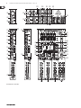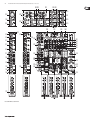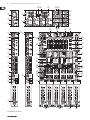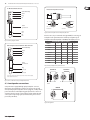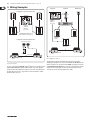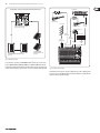
1
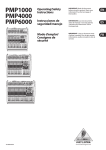
User Manual EUROPOWER PMP1000/PMP4000/PMP6000 500/1600-Watt 12, 16 and 20-Channel Powered Mixer with Multi/Dual Multi-FX Processor and FBQ Feedback Detection System 2 EUROPOWER PMP1000/PMP4000/PMP6000 User Manual Table of Contents Important Safety Instructions....................................... 3 Legal Disclaimer.............................................................. 3 Limited Warranty............................................................ 3 1. Introduction................................................................ 5 1.1 Before you get started....................................................... 5 1.1.1 Shipment........................................................................... 5 1.1.2 Initial operation.............................................................. 5 1.1.3 Online registration........................................................ 5 1.2 The manual............................................................................ 5 2. Control Elements........................................................ 9 2.1 Mono and stereo channels............................................... 9 2.1.1 Input section.................................................................... 9 2.2 Equalizer and FBQ............................................................. 10 2.3 Effects section ................................................................... 11 2.4 Main and monitor section.............................................. 11 2.4.1 Connectors..................................................................... 12 2.5 Rear panel............................................................................ 12 3. Digital Effects Processor.......................................... 12 4. Installation................................................................ 14 4.1 Mains connection.............................................................. 14 4.2 Audio connections............................................................ 14 4.3 Loudspeaker connections.............................................. 15 5. Wiring Examples....................................................... 16 6. Specifications............................................................ 19 3 EUROPOWER PMP1000/PMP4000/PMP6000 User Manual Important Safety Instructions Terminals marked with this symbol carry electrical current of sufficient magnitude to constitute risk of electric shock. Use only high-quality commercially-available speaker cables with 1/4" TS plugs pre-installed. All other installation or modification should be performed only by qualified personnel. This symbol, wherever it appears, alerts you to the presence of uninsulated dangerous voltage inside the enclosure - voltage that may be sufficient to constitute a risk of shock. This symbol, wherever it appears, alerts you to important operating and maintenance instructions in the accompanying literature. Please read the manual. Caution To reduce the risk of electric shock, do not remove the top cover (or the rear section). No user serviceable parts inside. Refer servicing to qualified personnel. Caution To reduce the risk of fire or electric shock, do not expose this appliance to rain and moisture. The apparatus shall not be exposed to dripping or splashing liquids and no objects filled with liquids, such as vases, shall be placed on the apparatus. 9. Do not defeat the safety purpose of the polarized or grounding-type plug. A polarized plug has two blades with one wider than the other. A grounding-type plug has two blades and a third grounding prong. The wide blade or the third prong are provided for your safety. If the provided plug does not fit into your outlet, consult an electrician for replacement of the obsolete outlet. 10. Protect the power cord from being walked on or pinched particularly at plugs, convenience receptacles, and the point where they exit from the apparatus. 11. Use only attachments/accessories specified by the manufacturer. 12. Use only with the cart, stand, tripod, bracket, or table specified by the manufacturer, or sold with the apparatus. When a cart is used, use caution when moving the cart/apparatus combination to avoid injury from tip-over. 13. Unplug this apparatus during lightning storms or when unused for long periods of time. 14. Refer all servicing to qualified service personnel. Servicing is required when the apparatus has been damaged in any way, such as power supply cord or plug is damaged, liquid has been spilled or objects have fallen into the apparatus, the apparatus has been exposed to rain or moisture, does not operate normally, or has been dropped. 15. The apparatus shall be connected to a MAINS socket outlet with a protective earthing connection. 16. Where the MAINS plug or an appliance coupler is used as the disconnect device, the disconnect device shall remain readily operable. Caution These service instructions are for use by qualified service personnel only. To reduce the risk of electric shock do not perform any servicing other than that contained in the operation instructions. Repairs have to be performed by qualified service personnel. 1. Read these instructions. 2. Keep these instructions. 3. Heed all warnings. 4. Follow all instructions. 5. Do not use this apparatus near water. 6. Clean only with dry cloth. 7. Do not block any ventilation openings. Install in accordance with the manufacturer’s instructions. 8. Do not install near any heat sources such as radiators, heat registers, stoves, or other apparatus (including amplifiers) that produce heat. Limited Warranty Limit § 1 Warranty (1) This limited warranty is valid only if you purchased the product from a BEHRINGER authorized dealer in the country of purchase. A list of authorized dealers can be found on BEHRINGER’s website behringer.com under “Where to Buy“, or you can contact the BEHRINGER office closest to you. (2) MUSIC Group* warrants the mechanical and electronic components of this product to be free of defects in material and workmanship if used under normal operating conditions for a period of one (1) year from the original date of purchase (see the Limited Warranty terms in § 4 below), unless a longer minimum warranty period is mandated by applicable local laws. If the product shows any defects within the specified warranty period and that defect is not excluded under § 4, MUSIC Group shall, at its discretion, either replace or repair the product using suitable new or reconditioned product or parts. In case MUSIC Group decides to replace the entire product, this limited warranty shall apply to the replacement product for the remaining initial warranty period, i.e., one (1) year (or otherwise applicable minimum warranty period) from the date of purchase of the original product. (3) Upon validation of the warranty claim, the repaired or replacement product will be returned to the user freight prepaid by MUSIC Group. (4) Warranty claims other than those indicated above are expressly excluded. PLEASE RETAIN YOUR SALES RECEIPT. IT IS YOUR PROOF OF PURCHASE COVERING YOUR LIMITED WARRANTY. THIS LIMITED WARRANTY IS VOID WITHOUT SUCH PROOF OF PURCHASE. § 2 Online registration Please do remember to register your new BEHRINGER equipment right after your purchase at behringer.com under “Support” and kindly read the terms and conditions of our limited warranty carefully. Registering your purchase and equipment with us helps us process your repair claims quicker and more efficiently. Thank you for your cooperation! § 3 Return materials authorization Legal Disclaimer Technical specifications and appearance are subject to change without notice. The information contained herein is correct at the time of printing. All trademarks are the property of their respective owners. MUSIC Group accepts no liability for any loss which may be suffered by any person who relies either wholly or in part upon any description, photograph or statement contained herein. Colors and specifications may vary slightly from product. BEHRINGER products are sold through authorized dealers only. Distributors and dealers are not agents of MUSIC Group and have absolutely no authority to bind MUSIC Group by any express or implied undertaking or representation. This manual is copyrighted. No part of this manual may be reproduced or transmitted in any form or by any means, electronic or mechanical, including photocopying and recording of any kind, for any purpose, without the express written permission of Red Chip Company Ltd. ALL RIGHTS RESERVED. © 2010 Red Chip Company Ltd. Trident Chambers, Wickhams Cay, P.O. Box 146, Road Town, Tortola, British Virgin Islands (1) To obtain warranty service, please contact the retailer from whom the equipment was purchased. Should your BEHRINGER dealer not be located in your vicinity, you may contact the BEHRINGER distributor for your country listed under “Support” at behringer.com. If your country is not listed, please check if your problem can be dealt with by our “Online Support” which may also be found under “Support” at behringer.com. Alternatively, please submit an online warranty claim at behringer.com BEFORE returning the product. All inquiries must be accompanied by a description of the problem and the serial number of the product. After verifying the product’s warranty eligibility with the original sales receipt, MUSIC Group will then issue a Return Materials Authorization (“RMA”) number. Lega 4 EUROPOWER PMP1000/PMP4000/PMP6000 User Manual (2) Subsequently, the product must be returned in its original shipping carton, together with the return authorization number to the address indicated by MUSIC Group. (3) Shipments without freight prepaid will not be accepted. § 4 Warranty Exclusions (1) This limited warranty does not cover consumable parts including, but not limited to, fuses and batteries. Where applicable, MUSIC Group warrants the valves or meters contained in the product to be free from defects in material and workmanship for a period of ninety (90) days from date of purchase. (2) This limited warranty does not cover the product if it has been electronically or mechanically modified in any way. If the product needs to be modified or adapted in order to comply with applicable technical or safety standards on a national or local level, in any country which is not the country for which the product was originally developed and manufactured, this modification/adaptation shall not be considered a defect in materials or workmanship. This limited warranty does not cover any such modification/adaptation, regardless of whether it was carried out properly or not. Under the terms of this limited warranty, MUSIC Group shall not be held responsible for any cost resulting from such a modification/adaptation. (3) This limited warranty covers only the product hardware. It does not cover technical assistance for hardware or software usage and it does not cover any software products whether or not contained in the product. Any such software is provided “AS IS” unless expressly provided for in any enclosed software limited warranty. (4) This limited warranty is invalid if the factoryapplied serial number has been altered or removed from the product. (5) Free inspections and maintenance/repair work are expressly excluded from this limited warranty, in particular, if caused by improper handling of the product by the user. This also applies to defects caused by normal wear and tear, in particular, of faders, crossfaders, potentiometers, keys/buttons, guitar strings, illuminants and similar parts. (6) Damage/defects caused by the following conditions are not covered by this limited warranty: • improper handling, neglect or failure to operate the unit in compliance with the instructions given in BEHRINGER user or service manuals; • connection or operation of the unit in any way that does not comply with the technical or safety regulations applicable in the country where the product is used; • damage/defects caused by acts of God/Nature (accident, fire, flood, etc) or any other condition that is beyond the control of MUSIC Group. (7) Any repair or opening of the unit carried out by unauthorized personnel (user included) will void the limited warranty. (8) If an inspection of the product by MUSIC Group shows that the defect in question is not covered by the limited warranty, the inspection costs are payable by the customer. (9) Products which do not meet the terms of this limited warranty will be repaired exclusively at the buyer’s expense. MUSIC Group or its authorized service center will inform the buyer of any such circumstance. If the buyer fails to submit a written repair order within 6 weeks after notification, MUSIC Group will return the unit C.O.D. with a separate invoice for freight and packing. Such costs will also be invoiced separately when the buyer has sent in a written repair order. (10) Authorized BEHRINGER dealers do not sell new products directly in online auctions. Purchases made through an online auction are on a “buyer beware” basis. Online auction confirmations or sales receipts are not accepted for warranty verification and MUSIC Group will not repair or replace any product purchased through an online auction. § 5 Warranty transferability This limited warranty is extended exclusively to the original buyer (customer of authorized retail dealer) and is not transferable to anyone who may subsequently purchase this product. No other person (retail dealer, etc.) shall be entitled to give any warranty promise on behalf of MUSIC Group. § 6 Claim for damage Subject only to the operation of mandatory applicable local laws, MUSIC Group shall have no liability to the buyer under this warranty for any consequential or indirect loss or damage of any kind. In no event shall the liability of MUSIC Group under this limited warranty exceed the invoiced value of the product. § 7 Limitation of liability This limited warranty is the complete and exclusive warranty between you and MUSIC Group. It supersedes all other written or oral communications related to this product. MUSIC Group provides no other warranties for this product. § 8 Other warranty rights and national law (1) This limited warranty does not exclude or limit the buyer’s statutory rights as a consumer in any way. (2) The limited warranty regulations mentioned herein are applicable unless they constitute an infringement of applicable mandatory local laws. (3) This warranty does not detract from the seller’s obligations in regard to any lack of conformity of the product and any hidden defect. § 9 Amendment Warranty service conditions are subject to change without notice. For the latest warranty terms and conditions and additional information regarding MUSIC Group’s limited warranty, please see complete details online at behringer.com. * MUSIC Group Macao Commercial Offshore Limited of Rue de Pequim No. 202-A, Macau Finance Centre 9/J, Macau, including all MUSIC Group companies 5 EUROPOWER PMP1000/PMP4000/PMP6000 User Manual 1. Introduction Congratulations! With the PMP1000/PMP4000/PMP6000 you have acquired a state-of-the-art power mixer that sets new standards. Right from the very start it has been our goal to design a revolutionary unit that can be used for a wide variety of applications. Indeed, this overwhelming power mixer gives you plenty of functionality and a broad range of connection and expansion options. Further advantages are the integrated Voice Canceller that removes vocal passages from playbacks, the FBQ function, which detects feedback frequencies, and the Speaker Processing function for loudspeaker alignment—all with a resolution of 24 bits and 40 kHz. Plus, our tried and tested XENYX Mic Preamps give you crystal-clear audio free of noise and distortion when using microphones. BEHRINGER is a company with its roots in professional recording studio technology. For many years we have been successful in developing products for studio and live use. These include microphones and 19" units of all types (compressors, enhancers, noise gates, tube processors, headphone amplifiers, digital effects, DI boxes, etc.), monitor and P.A. speakers and professional live and recording mixers. Our entire technical know-how has gone into your PMP power mixer. 1.1 Before you get started 1.1.1 Shipment Your PMP was carefully packed at the factory and the packaging is designed to protect the unit from rough handling. Nevertheless, we recommend that you carefully examine the packaging and its contents for any signs of physical damage which may have occurred during transit. ◊ If the unit is damaged, please do NOT return it to BEHRINGER, but notify your dealer and the shipping company immediately. Otherwise, claims for damage or replacement may not be granted. ◊ We recommend that you use a flight case, so as to give your power mixer optimum protection during use or transport. ◊ Always use the original packing carton to prevent damage during storage or transport. ◊ Make sure that children cannot play unsupervised with the device or its packaging. ◊ Please ensure proper disposal of all packing materials. 1.1.2 Initial operation Be sure that there is enough air space around the unit for cooling and, to avoid overheating, please do not place the EUROPOWER near radiators, etc. ◊ Blown fuses must be replaced by fuses of the same type and rating! Please refer to the “Specifications” for details. The mains connection is made using the enclosed power cord and a standard IEC receptacle. It meets all of the international safety certification requirements. ◊ Please make sure that all units have a proper ground connection. For your own safety, never remove or disable the ground conductor from the unit or on the AC power cord. To avoid damage on the device, do not • earth the loudspeaker outputs • connect the loudspeaker outputs to each other • connect the loudspeaker outputs to those of other amplifiers IMPORTANT NOTES CONCERNING INSTALLATION The sound quality may diminish within the range of powerful broadcasting stations and high-frequency sources. Increase the distance between the transmitter and the device and use shielded cables for all connections. 1.1.3 Online registration Please register your new BEHRINGER equipment right after your purchase by visiting http://behringer.com and read the terms and conditions of our warranty carefully. Should your BEHRINGER product malfunction, it is our intention to have it repaired as quickly as possible. To arrange for warranty service, please contact the BEHRINGER retailer from whom the equipment was purchased. Should your BEHRINGER dealer not be located in your vicinity, you may directly contact one of our subsidiaries. Corresponding contact information is included in the original equipment packaging (Global Contact Information/European Contact Information). Should your country not be listed, please contact the distributor nearest you. A list of distributors can be found in the support area of our website (http://behringer.com). Registering your purchase and equipment with us helps us process your repair claims more quickly and efficiently. Thank you for your cooperation! 1.2 The manual This manual is designed to give you both an overview of all control elements and to provide details about how to use them. To provide you with a clear structure, we have grouped the control elements according to their function. They can easily be found on the enclosed numbered illustrations. If you need more detailed information on specific topics, please visit our web site at behringer.com. 6 EUROPOWER PMP1000/PMP4000/PMP6000 User Manual (57) (58) (61) (62) (65) (55) (18) (35) (19) (22) (20) (60) (64) (1) (2) (21) (27) (26) (30) (3) (4) (6) (8) (31) (9) (36) (43) (11) (13) (14) (32) (33) (34) (39) (37) (56) (44) (42) (40) (52) (29) (16) (17) (47) EUROPOWER PMP1000 FRONT PANEL (46) (54) (48) 7 EUROPOWER PMP1000/PMP4000/PMP6000 User Manual (56) (55) (57) (58) (59) (62) (18) (23) (63) (64) (19) (22) (65) (20) (26) (1) (2) (60) (61) (27) (43) (44) (21) (3) (4) (24) (31) (34) (32) (30) (33) (5) (6) (25) (8) (9) (35) (54) (10) (36) (38) (53) (37) (40) (42) (52) (11) (13) (15) (16) (14) (45) (41) (17) (46) EUROPOWER PMP4000 FRONT PANEL (47) (48) (49) 8 EUROPOWER PMP1000/PMP4000/PMP6000 User Manual (56) (55) (57) (58) (59) (62) (18) (23) (63) (19) (64) (22) (20) (65) (26) (1) (2) (60) (61) (27) (28) (29) (21) (3) (4) (34) (31) (24) (5) (6) (32) (25) (33) (7) (8) (35) (9) (36) (11) (12) (15) (16) (53) (37) (10) (13) (54) (14) (38) (39) (52) (42) (43) (40) (44) (50) (41) (51) (45) (17) (46) EUROPOWER PMP6000 FRONT PANEL (47) (48) (49) 9 EUROPOWER PMP1000/PMP4000/PMP6000 User Manual (66) (67) (69) (70) (68) (72) (71) EUROPOWER PMP6000 REAR PANEL 2. Control Elements A detailed description of all functions of your power mixer can be found in the following chapters. Please also refer to the enclosed sheet with the numbered illustrations to get a good overview of the control layout. 2.1 Mono and stereo channels (1) Use the GAIN control to adjust the input gain. Be sure to set this control fully counter-clockwise before you connect or disconnect a signal source to an input. GAIN controls both the microphone and the LINE input. The black scale shows the microphone gain (+10 to +60 dB on channels with XENYX MIC PREAMPS and 0 to +40 dB on conventional microphone inputs; PMP1000 only, channels 5/6 and 7/8). The “LINE” scale indicates the sensitivity of the LINE input, ranging from +10 to -40 dBu. PMP1000: The mono/stereo combination channels 5/6 and 7/8 have a sensitivity of +20 to -20 dBu. (2) The LEVEL SET LED illuminates when an optimum operating level has been adjusted. (3) The mono channels are equipped with a high-slope LOW CUT filter eliminating unwanted low-frequency signals like rumble noise. (4) PMP4000/PMP6000 (stereo channels): Press the A/B button to switch from 1/4" jacks to RCA connectors, and vice versa. Position “A” = 1/4" jacks; position “B” = RCA connectors. (5) The HIGH control in the EQ section governs the high frequency range of the respective channel. (6) Use the MID control to boost or cut the midrange frequencies. (7) PMP6000: The PMP6000 has an additional semi-parametric filter for the midrange frequencies in the mono channels (tunable from 100 Hz to 8 kHz). Adjust the boost/cut with the MID control, and the frequency with the FREQ control. The stereo channels contain a stereo EQ section. The cut-off frequencies of the high and low bands are 12 kHz and 80 Hz respectively, while the center frequencies of the high-mid and low-mid bands are 3 kHz and 400 Hz respectively. (8) The LOW control allows you to boost/cut the low frequency range. (9) With the MON(ITOR) control you can adjust the volume of each channel in the monitor mix. (10) The PMP4000 and PMP6000 feature a second MON control (MON 2) for the volume of the second monitor bus. (11) The FX control determines the signal level sent from each channel to the built-in effects processor; this signal is also present at the FX SEND jack (see (64) ). (12) The PMP6000 has two FX controls (FX 1 and FX 2), so that you can use two effects simultaneously. Accordingly, the PMP6000 also has two effect aux buses, which have one output jack in common (see (46) and (64) ). ◊ Please note that the effects processor signal will be inaudible, as long as the FX TO MON/MAIN controls (40) , (41) , (42) are set fully counter-clockwise. (13) The PAN(ORAMA) control determines the position of the channel signal in the stereo main mix. (14) The BAL(ANCE) control for the stereo channels corresponds to the PAN control for the mono channels. It determines the relative volume of the left and right input signals before they are routed to the stereo main output. (15) PMP4000/PMP6000: When you press the PFL button (Pre Fader Listening) the left LED (34) shows the pre-fader input gain of the channel. Adjust the optimum input gain (0 dB) with the GAIN control (1) . When PFL is on, the corresponding LED illuminates. If the LEVEL SET LED (2) is illuminated constantly, the signal is within the optimum operating level range. However, if the CLIP LED indicates that the input gain is too high, you should reduce the level slightly with the GAIN control. The CLIP LED should never be illuminated all the time, only with signal peaks. (16) The MUTE switch mutes the channel in the main mix. The pre-fader signals (monitor buses) remain operative. When MUTE is pressed, the corresponding control LED illuminates. (17) The channel fader controls the channel signal level in the main mix. 2.1.1 Input section (18) Each mono input channel is equipped with a balanced microphone input (XLR connector) which provides +48 V phantom power for condenser microphones at the touch of a button (see rear panel). PMP1000: The two stereo channels 5/6 and 7/8 have an additional balanced XLR microphone input with +48 V phantom power. ◊ Be sure to switch off your audio system before you activate the phantom power supply to protect your monitor speakers from switch-on thumps. (19) Each mono input features one LINE IN connector (1/4" jack), which can be used with either balanced or unbalanced signals. ◊ Please remember to use either the microphone or the line input on a specific channel. Never use both at the same time! ◊ When you connect a mono line signal to a stereo channel, always use the left input. The mono signal will then be reproduced by both sides equally. 10 EUROPOWER PMP1000/PMP4000/PMP6000 User Manual ◊ PMP1000: This does not apply to the mono/stereo combination channels 5/6 and 7/8. (27) The AMP MODE switch determines the mode of operation of the PMP amplifier stage: (20) INSERT I/O. Insert points or simply inserts are used to process a signal with dynamic processors or equalizers. They are pre-fader, pre-EQ and pre-MON/ FX SEND. Unlike reverb and other effects, which are usually added to the dry signal, dynamic processors usually process the entire signal. So, aux send buses are not the best solution. Dynamic processors need to be inserted directly into the signal path. Once processed, the signal then returns to the mixing console at the same point where it left. Signal interruption takes place only if a plug is inserted into the corresponding jack (1/4" stereo plug: tip = signal output, ring = input). All mono input channels are equipped with inserts. PMP1000: (21) The stereo channels have a GAIN control for gain adjustment, with the input sensitivity ranging from +20 to -20 dB. MAIN L/MAIN R. In position MAIN MIX, the mixer works as a stereo amplifier. PMP1000: The stereo channels 5/6 and 7/8 feature an additional XLR connector for microphones whose gain can be set from 0 to +40 dB. (22) Each stereo channel has two line-level inputs (1/4" jacks) for the left and right channels. If only the jack marked “L” is used, the channel is mono. The signal will then be reproduced on both sides. ◊ PMP1000: This does not apply to the mono/stereo combination channels 5/6 and 7/8. ◊ PMP1000: Channels 13/14 and 15/16 are routed to the main mix without additional tone or volume adjustment. For example, using the channels 13/14 and 15/16 you can connect a submixer and utilize the PMP1000’s power amplifier. (23) PMP4000: The stereo channels 9/10 and 11/12 are equipped with additional RCA connectors. PMP6000: The stereo channels 13/14 and 15/16 are equipped with additional RCA connectors. ◊ PMP4000/PMP6000: Please note that you need to set the A/B selector (4) to A (1/4") or B (RCA) when you connect a signal to the input. MAIN: In the “MAIN” position the mixer works as a stereo amplifier. MON: In this mode the monitor signal is present at OUTPUT A (71) and the main signal at OUTPUT B (70) (both are mono). BRIDGE (bridged mono mode): In BRIDGE AMP MODE the output power of OUTPUT A is added to that of OUTPUT B, i.e. OUTPUT B delivers twice its normal output power. PMP4000/PMP6000: MON 1/MONO. In this mode the monitor 1 signal is present at OUTPUT A (71) and the main signal at OUTPUT B (70) (both are mono). BRIDGE (bridged mono mode): In BRIDGE AMP MODE the output power of OUTPUT A is added to that of OUTPUT B, i.e. OUTPUT B delivers twice its normal output power. ◊ In BRIDGE mode, always connect only one loudspeaker with an impedance of at least 8 Ω to the OUTPUT B jack! Please note that OUTPUT A must NEVER be used in BRIDGE mode! ◊ In all other operating modes, the minimum impedance of the speaker must not fall below 4 Ω. ◊ Please note that the power delivered to the speaker connected to OUTPUT B in BRIDGE AMP MODE is considerably higher than the power provided to the speakers wired to the parallel speaker outputs. Please read the information given on the rear panel of the power mixer. ◊ Information on how to properly connect your speaker with regard to polarity can be found on the rear of the unit (PIN assignment) (see also (71) and (42) ). (25) Instead of a fader this channel has a rotary LEVEL control. (28) PMP6000: Use the BEHRINGER SPEAKER PROCESSING switch to activate a filter that allows you to adapt the mixer to the characteristics of your loudspeakers. If the speakers have a limited frequency response in the bass range, this function allows you to filter this range at the output signal of the mixer and thus adapt it optimally to the frequency response of the speakers. (26) The phantom power supply provides the voltage necessary for the operation of condenser microphones. Use the PHANTOM switch to activate the supply for the XLR connectors of the input channels. The +48 V LED will illuminate when phantom power is on. In most cases, dynamic microphones can still be used, as long as they are connected in a balanced configuration. If in doubt, please contact the manufacturer of your microphone! (29) PMP1000/PMP6000: If STANDBY is pressed, all input channels are muted. During pauses you can prevent the microphones from picking up noise or interference, which would then be reproduced by the P.A. system or possibly damage the speaker diaphragms. The benefit is that all faders can be left untouched while you play back music from CD via the CD/TAPE inputs (see (55) ). There is also no need to move the faders and lose your mix. ◊ With phantom power switched on, you must never connect 2.2 Equalizer and FBQ (24) PMP4000/PMP6000: Each of the two stereo channels has two monitor controls (MON 1/2) and a LEVEL control (25) . Like the other channels, they also feature a PFL switch. microphones to the console (or to a stage/wall box). Also, be sure to mute the monitor/P.A. speakers, before you turn on the phantom power supply. After switching on, please allow the system to stabilize for about one minute, before you adjust the input gain. ◊ Caution! Never use unbalanced XLR connectors (pins 1 and 3 interconnected) on the MIC input jacks, if you are going to use the phantom power supply. (30) Your power mixer features a graphic 7-band equalizer, which allows you to fine-tune the sound depending on the room acoustics. In the center position the frequency response is not effected. To boost or cut a certain frequency range, simply move the corresponding fader upward or downward respectively. ◊ Please note that the equalizer behaviour depends on the position of the AMP MODE switch (see (27) ). 11 (31) EUROPOWER PMP1000/PMP4000/PMP6000 User Manual Press the FBQ IN switch to activate the Feedback Detection system (the FBQ will be active only if you have switched on the equalizer (33) before). Frequencies causing feedback are shown by brightly lit fader LEDs. All other LEDs will be darker. Now, cut the frequency range in question until feedback disappears (the LED gets darker or goes out). This function is available for both the main and monitor mix. PMP1000: The switch FBQ FEEDBACK DETECTION performs the same function as on the PMP4000 and PMP6000. (32) Use the MAIN/MON 1 switch to select whether the equalizer processes the main or the monitor mix. When not pressed, the stereo equalizer processes only the main mix. When the switch is pressed, the EQ processes only the monitor mix. PMP1000: The MAIN MIX/MONITOR switch performs the same function as on the PMP4000 and PMP6000. (33) Press the EQ IN switch to activate the equalizer. The fader LEDs illuminate when the EQ is on. (34) Use this LED display to control the output level of the main signal. The upper LIM LED illuminates when the internal amp protection circuit responds to levels that are too high. PMP1000: The POWER LED is illuminated when you switch the unit on. ◊ The LIM LEDs and the LED display do NOT light up when an external signal is fed in via the PWR AMP INSERT jacks (61) . (42) The FX 1/2 TO MAIN control allows you to determine the effect intensity of the multi-effects processor in the main mix. No effect is sent to the main mix with this control turned fully counter-clockwise. PMP1000: The FX TO MAIN control performs the same function as on the PMP4000 and PMP6000. 2.4 Main and monitor section The surround control determines the effect intensity. This is a built-in effect, which widens the stereo panorama, thus making the sound more lively and transparent. (43) (44) Press the XPQ TO MAIN switch to activate this effect. (45) Pressing the AFL switch (after-fader listening) activates the solo function. If AFL is on for the corresponding channel in the main section, you will only hear the signal from this channel. Its volume can be adjusted with the fader. Switching AFL on has no effect on the main or monitor mix, as long as you don’t move the fader. In this way, you can monitor one or several selected signals via the PHONES/CTRL jack (65) . When AFL is on, the corresponding control LED illuminates. ◊ The PMP1000 does not have an AFL function. (46) PMP1000: FX SEND fader. PMP4000: FX fader. PMP6000: FX 1/2 fader. This is the master send fader for the signal routed to the effects processor and to the FX SEND output (63) (see also (11) and (12) ). 2.3 Effects section (35) List of all multi-effects processor presets. (36) The LED level meter on the effects module should always show a sufficiently high level. Make sure that the Clip LED illuminates with signal peaks only. If it is constantly illu-minated, the effects processor is overloading, which can lead to unpleasant distortion. The FX SEND fader (PMP1000) or FX/FX 1/2 fader (PMP4000/PMP6000) controls the level sent to the effects module and to the FX SEND output jacks. (47) PMP1000: MON SEND fader. PMP4000/PMP6000: MON 1/2 fader. These faders are used to set the monitor output volume (see also (9) and (10) ). (48) PMP1000: The main mix allows you to control the volume from the Main 1 output with both faders. (37) The effects display always reads the currently selected preset. PMP4000/PMP6000: The MAIN 1 fader controls the volume of the EUROPOWER. The main signal is also provided at the MAIN 1 output (see also (58) ). (38) PMP4000/PMP6000: Press the FX1/2 IN switch to activate the effects processor. (49) PMP4000/PMP6000: The MONO fader controls the mono mix signal (see also (63) ). (39) PMP1000/PMP4000: Turn the PROGRAM control to select an effects algorithm (preset number starts flashing). Press this control to activate the effect selected (PMP6000: FX 1/2 (PUSH)). (50) PMP6000: The SUB FILTER filters out frequencies above the selected setting, so that only low frequencies are sent to an (active) subwoofer via the MONO OUT (63) ). Set this switch to “On” to activate the filter. ◊ PMP1000: The effects processor is operative all the time. Adjust the (51) PMP6000: The SUB FREQ control determines the cut-off frequency for the subwoofer output. This value can be adjusted from 30 to 200 Hz. effect intensity for the MAIN or MON signals with controls (40) or (42) respectively. PMP6000: The PMP6000 has two separate effects processors, which can be used independently of one another. Enable one or both processors with the FX1/2 IN (38) buttons. (40) PMP4000/PMP6000: The FX 1/2 TO MON 1 control allows you to set the intensity of the multi-effects processors in the monitor mix. No effect is sent to the monitor mix when this control is set fully counter-clockwise. PMP1000: The FX TO MON control performs the same function as on the PMP4000 and PMP6000. (41) The FX 1/2 TO MON 2 control allows you to determine the effect intensity of the multi-effects processor in the monitor 2 mix. No effect is sent to the monitor 2 mix with this control turned fully counter-clockwise. (52) The PHONS/CTRL R control adjusts the headphone or control room volume (see also (65) ). (53) PMP4000/PMP6000: The MAIN 2 control determines the volume at the MAIN 2 output (see also (59) ), which is the same signal as at MAIN 1, but with extra output jacks and separate volume control. (54) PMP4000/PMP6000: With the CD/TAPE IN control you can adjust the volume of the line signal present at the CD/TAPE INPUT (55) . Use the PFL switch to monitor the signal. PMP1000: With the CD/TAPE RET fader you can adjust the line signal applied to the CD/TAPE INPUT (55) . Use the CD/TAPE MUTE switch to mute the channel. 12 EUROPOWER PMP1000/PMP4000/PMP6000 User Manual 2.4.1 Connectors (55) Use the CD/TAPE INPUT jacks (RCA) to connect an external stereo signal, such as a CD player, tape deck or other line-level sources. (56) The VOICE CANCELLER filters vocal-specific frequencies from the CD/TAPE INPUT signal. This function can be used for karaoke, i.e. you can remove the vocals from a song and then sing along with the music yourself. (57) The CD/TAPE OUTPUT provides the line level stereo signal (e.g. for a DAT recorder). ◊ If the CD/TAPE OUT signal is connected to a recording machine whose output signal is returned to the CD/TAPE IN, feedback can occur when you activate the record function on the recording machine. So, disconnect the CD/TAPE IN from the recording machine before you start recording or set the CD/TAPE input signal to zero! (58) PMP1000: The MAIN OUT jacks allow you to send the main line level signal to an external amplifier, when, for example, you want to use the mixer and effects section. The PMP4000 and PMP6000 have two separately controllable line level MAIN outputs (59) (MAIN 1/2). ◊ Please note: The SEND signal is in parallel with the FX SEND jacks and with the effects processor, so that both can be controlled together by one control. ◊ For the FX signals, use a 1/4" stereo plug connected as follows: FX1 = tip; FX2 = ring (65) The PHONS/CTRL connector allows you to connect a pair of stereo headphones or an (active) monitor speaker. 2.5 Rear panel (66) The mains connection is via a standard IEC receptacle. An appropriate power cord is supplied with the unit. (67) FUSE HOLDER. Before connecting the unit to the mains, ensure that the voltage setting matches your local voltage. Blown fuses should only be replaced by fuses of the same type and rating. Please also read the information given in the “Specifications”. (68) Use the POWER switch to put your PMP into operation. The POWER switch should always be in the “Off” position before connecting your unit to the mains. (60) Connect your monitor power amps or active monitor speakers to the MON 1/2 SEND to monitor the signal mix created with the MON controls or to route it to the musicians on stage. ◊ Please note: The POWER switch does not fully disconnect the unit from (61) The PMP Series comes with a POWER AMP INSERT connection that is provided for various applications. This connection enables you to use the power amplifier of the device to amplify the output signal of another preamp. For example, it is possible to connect a larger mixer or preamp output (line signal) of an instrument amplifier. In this case, you only need an unbalanced, mono jack cable. (69) SERIAL NUMBER. Furthermore, it is possible to use the POWER AMP INSERT as a conventional insert to add a compressor or graphic equalizer to the signal path, for instance. Here, a balanced, stereo jack cable is required and the assignment of tip and ring needs to be observed according to Figure 4.5 (see Chapter 4.2 “Audio Connections”). In this case, the ring is the so-called Send, which is connected to the input of the additional device, and the tip is referred to as Return, which is connected to the output of the additional device. Lastly, it is possible to tap the output signal of the device’s mixer section from the POWER AMP INSERT in order to use a second, external power amp. A balanced, stereo jack cable is required with the ring (not the tip) connected to the input of the external power amp. If you want to use the internal and external power amps at the same time, just wire the connector’s ring and tip together. (62) The FOOTSWITCH jack is for a standard footswitch. You can activate an “effect bypass”, thereby muting the effects processor. Use a dual foot switch for the PMP6000, so that you can enable/disable FX1 and FX2 independently of each other. In this case, the tip of the 1/4" plug controls FX1, and the ring FX2. (63) PMP4000/PMP6000: The MONO OUT is for connecting a subwoofer. The PMP6000 has the additional possibility of setting the low-frequency range for the subwoofer. Use the SUB FILTER control (50) to adjust the frequency. (64) The FX SEND connector can be used to route the FX SEND signal from the input channel, for example, to the input of an external effects device. Since the PMP6000 has two FX controls per input signal (see (12) ), both FX SEND 1+2 are present at one jack. the mains. Unplug the power cord completely when the unit is not used for prolonged periods of time. (70) This is where you find the cooling fan of the unit. The PMP6000 has two cooling fans. (71) OUTPUT A (LEFT) provides either the left stereo main signal or the monitor signal in mono, depending on the operating mode selected (see (27) ). NEVER use this output in bridged mono mode. (72) OUTPUT B (RIGHT/BRIDGE) provides either the right stereo main signal, the main mix signal (mono) or the bridged mono signal, depending on the operating mode selected. ◊ In BRIDGE mode always connect only one loudspeaker with an impedance of at least 8 Ω to the OUTPUT B jack! NEVER use OUTPUT A in BRIDGE mode! ◊ In all other operating modes the impedance of the connected loudspeaker must not fall below 4 Ω. 3. Digital Effects Processor 24-BIT MULTI-EFFECTS PROCESSOR This built-in effects module produces high-grade standard effects such as reverb, chorus, flanger, delay and various combination effects. The integrated effects module has the advantage of requiring no wiring. This way, the danger of creating ground loops or uneven signal levels is eliminated at the outset, completely simplifying the handling. These effect presets are designed to be added to dry signals. ◊ Turn down the FX controls in those channel strips whose signals you don’t wish to process. 13 EUROPOWER PMP1000/PMP4000/PMP6000 User Manual Effect Presets of EUROPOWER PMP6000 No. 00 01 02 03 04 05 06 07 08 09 10 11 12 13 14 15 16 17 18 19 20 21 22 23 24 25 26 27 28 29 30 31 32 33 34 35 36 37 38 39 40 41 42 43 44 45 46 47 48 49 EFFECT Description HALL 00-09 SMALL HALL 1 approx. 1.0s reverb decay SMALL HALL 2 approx. 1.2s reverb decay SMALL HALL 3 approx. 1.5s reverb decay MID HALL 1 approx. 1.8s reverb decay MID HALL 2 approx. 2.0s reverb decay MID HALL 3 approx. 2.5s reverb decay BIG HALL 1 approx. 2.8s reverb decay BIG HALL 2 approx. 3.2s reverb decay BIG HALL 3 approx. 4s reverb decay CHURCH approx. 7s reverb decay ROOM 10-19 SMALL ROOM 1 approx. 0.5s reverb decay SMALL ROOM 2 approx. 0.8s reverb decay SMALL ROOM 3 approx. 1.0s reverb decay MID ROOM 1 approx. 1.2s reverb decay MID ROOM 2 approx. 1.5s reverb decay MID ROOM 3 approx. 1.8s reverb decay BIG ROOM 1 approx. 2.0s reverb decay BIG ROOM 2 approx. 2.2s reverb decay BIG ROOM 3 approx. 2.5s reverb decay CHAPEL approx. 3s reverb decay PLATE 20-29 SHORT PLATE approx. 1.0s reverb decay MID PLATE approx. 1.5s reverb decay LONG PLATE approx. 2.2s reverb decay VOCAL PLATE approx. 1.2s reverb decay DRUMS PLATE approx. 1.0s reverb decay GOLD PLATE 1 approx. 1.2s reverb decay GOLD PLATE 2 approx. 2.0s reverb decay SHORT SPRING approx. 1.0s reverb decay MID SPRING approx. 2.0s reverb decay LONG SPRING approx. 2.5s reverb decay GATED/REVERSE 30-39 GATED REV SHORT approx. 0.8s gate time GATED REV MID approx. 1.2s gate time GATED REV LONG approx. 2.0s gate time GATED REV XXL approx. 3.0s gate time GATED REV DRUMS 1 approx. 0.8s gate time GATED REV DRUMS 2 approx. 1.2s gate time REVERSE SHORT approx. 0.8s reverb raise REVERSE MID approx. 1.2s reverb raise REVERSE LONG approx. 2.0s reverb raise REVERSE XXL approx. 3.0s reverb raise EARLY REFLECTIONS 40-49 EARLY REFLECTION 1 Short EARLY REFLECTION 2 Medium-short EARLY REFLECTION 3 Medium-long EARLY REFLECTION 4 Long SHORT AMBIENCE Short MID AMBIENCE Medium-short LIVE AMBIENCE Medium-short BIG AMBIENCE Medium-long STADIUM Long GHOST AMBIENCE Extra-long special FX No. EFFECT 50 51 52 53 54 55 56 57 58 59 SHORT DELAY 1 SHORT DELAY 2 SHORT DELAY 3 MID DELAY 1 MID DELAY 2 MID DELAY 3 LONG DELAY 1 LONG DELAY 2 LONG DELAY 3 LONG ECHO 60 61 62 63 64 65 66 67 68 69 SOFT CHORUS 1 SOFT CHORUS 2 WARM CHORUS 1 WARM CHORUS 2 PHAT CHORUS 1 PHAT CHORUS 2 CLASSIC FLANGER WARM FLANGER DEEP FLANGER HEAVY FLANGER 70 71 72 73 74 75 76 77 78 79 CLASSIC PHASER WARM PHASER DEEP PHASER HEAVY PHASER PITCH SHIFT DETUNE PITCH SHIFT +3 PITCH SHIFT +4 PITCH SHIFT +7 PITCH SHIFT -5 PITCH SHIFT -12 80 81 82 83 84 85 86 87 88 89 CHORUS + REVERB 1 CHORUS + REVERB 2 FLANGER + REVERB 1 FLANGER + REVERB 2 PHASER + REVERB 1 PHASER + REVERB 2 PITCH + REVERB 1 PITCH + REVERB 2 DELAY + REVERB 1 DELAY + REVERB 2 90 91 92 93 94 95 96 97 98 99 DELAY + GATED REV DELAY + REVERSE DELAY + CHORUS 1 DELAY + CHORUS 2 DELAY + FLANGER 1 DELAY + FLANGER 2 DELAY + PHASER 1 DELAY + PHASER 2 DELAY + PITCH 1 DELAY + PITCH 2 Description DELAY 50-59 Like a short shattering 1-2 short impulse(s) 1-2 short impulse(s) Classical Delay for up-tempo music (115-125 BPM) Classical Delay for mid-tempo music (105-115 BPM) Classical Delay for slow-tempo music (95-105 BPM) Classical Delay for reggae-tempo music (85-95 BPM) Classical Delay for dub-tempo music (75-85 BPM) Extra long (nearly infinite) delay effect Extra long canyon echo effect CHORUS 60-69 Unobtrusive effect Unobtrusive effect with different color Analog sounding Analog sounding with different color Pronounced chorus effect Pronounced chorus effect with different color Standard flanger effect More analog touch Deep modulation impression Extremely pronounced effect PHASE/PITCH 70-79 Standard phaser effect More analog touch Deep modulation impression Extreme strong effect 2-3-times detune for a wider solo voice sound Minor third added voice Major third added voice Quint above added voice Fourth down added voice 1 octave down added voice MULTI 1 80-89 Soft chorus + medium-short reverb Deep chorus + medium-long reverb Soft flanger + medium-short reverb Deep flanger + medium-long reverb Soft phaser + medium-short reverb Deep phaser + medium-long reverb Soft voice detuning + medium-short reverb Fourth above interval + medium-long reverb Short delay + medium-short reverb Medium-long delay + medium-long reverb MULTI 2 90-99 Short delay + medium-long gated reverb Medium-short delay + medium-long reverse reverb Short delay + soft chorus Medium-long delay + deep chorus Short delay + soft flanger Medium-long delay + deep flanger Short delay + soft phaser Medium-long delay + deep phaser Short delay + fourth down interval Medium-long delay + minor third above interval 14 EUROPOWER PMP1000/PMP4000/PMP6000 User Manual 4. Installation 4.1 Mains connection Balanced ¼" TRS connector strain relief clamp The mains connection is made using the enclosed power cord and a standard IEC receptacle. It meets all of the international safety certification requirements. sleeve ring Blown fuses must be replaced by fuses of the same type and rating. tip ◊ Please make sure that all units have a proper ground connection. For your own safety, never remove or disable the ground conductor from the unit or of the AC power cord. 4.2 Audio connections sleeve ground/shield The inputs and outputs of your BEHRINGER EUROPOWER are unbalanced 1/4" mono jacks—except for the mono channel line inputs, which are balanced 1/4" stereo jacks. Of course, all inputs and outputs work with both balanced and unbalanced connectors. The tape in and outputs are on RCA connectors. ring cold (-ve) tip hot (+ve) ◊ Please ensure that only qualified personnel install and operate the PMP. During installation and operation, the user must have sufficient electrical contact to earth. Electrostatic charges might affect the operation of the unit. For connection of balanced and unbalanced plugs, ring and sleeve have to be bridged at the stereo plug. Fig. 4.2: ¼" TRS connector Unbalanced ¼" TS connector Strain relief clamp Balanced use with XLR connectors Sleeve 2 1 3 Tip input Sleeve (ground/shield) 1 = ground/shield 2 = hot (+ve) 3 = cold (-ve) 1 2 3 Tip (signal) output Fig. 4.1: ¼" TS connector For unbalanced use, pin 1 and pin 3 have to be bridged Fig. 4.3: XLR connectors 15 EUROPOWER PMP1000/PMP4000/PMP6000 User Manual ¼" TRS footswitch connector Professional speaker connector strain relief clamp sleeve ring tip 1+ 1+ 1- 2sleeve ground/shield 1- 2+ 2+ front view ring FX2 tip FX1 2- rear view Fig. 4.6: Professional speaker connector with polarity allocation Please be sure to only use commercial cables (type NL4FC) for connecting your loudspeakers to the power mixer. Please check the pin assignment of your loudspeakers and cables dependent on the PMP speaker output you choose. Fig. 4.4: ¼" mono plug for footswitch EUROPOWER PMP1000/PMP4000/PMP6000 OUTPUT A 1+ 1- MAIN L x x strain relief clamp MONITOR x x sleeve MONO x x 1+ 1- MAIN R x x MONO x x MONO x x BRIDGE x Power amp insert send return ¼" TRS connector ring tip sleeve ground/shield OUTPUT B OUTPUT B 2+ 2- x x 2+ 2- x Tab. 4.1: Polarity configuration of speaker connectors ring send (out) OUTPUT B OUTPUT B tip return (in) 1+ 1+ Connect the insert send with the input and the insert with the output of the output effects device. Fig. 4.5: Stereo ¼" TRS connector for power amp ISR connection 4.3 Loudspeaker connections Your power mixer is equipped with high-quality loudspeaker connectors , which ensure safe and trouble-free operation. The connector was especially developed for high-power loudspeakers. Once it is plugged in, it safely locks into position and cannot be accidentally disengaged. It prevents the occurrence of electrical shock and ensures the correct polarity. Each of the loudspeaker jacks carries only the assigned single signal (see the information given on the rear panel of the power mixer). 1- 8Ω 4Ω 1- 8Ω 4Ω BRIDGE 1+ 16 Ω 8Ω 2+ Fig. 4.7: Pin assignment 16 EUROPOWER PMP1000/PMP4000/PMP6000 User Manual 5. Wiring Examples Subwoofer F.O.H. mix Monitor mix Loudspeaker connection (monitor mix) PMP1000 PMP4000 PMP6000 Rear panel EUROPOWER EP2000 PMP1000 PMP4000 PMP6000 (part view) 2 x BEHRINGER EUROLIVE Stack (B1800X & B1220, both passive) Loudspeaker connection (monitor mix) EUROLIVE VP1520 front panel (part view) EUROLIVE B1800X Subwoofer Footswitch Link Output 2 x BEHRINGER F1220D (active) Fig. 5.1: Stereo operation For stereo operation the POWER AMP switch (27) must be set to its upper position (MAIN or MAIN L/MAIN R). Outputs A and B provide the stereo main signal for passive speakers. The preamp monitor output is connected to two parallel active speakers, which are used as on-stage monitors. Use the footswitch to enable/ disable the effects processor. 2 x BEHRINGER F1220D (active) Fig. 5.2: Bridged mono operation This illustration shows the power mixer with a sub-woofer connected to OUTPUT B. For a bridged mono operation to OUTPUT B, the AMP MODE selector switch (27) must be set to its lower position “BRIDGE”. A separate stereo power amp (BEHRINGER EUROPOWER EP2000) connected to the preamp main outputs delivers the stereo main signal. Two active monitor speakers for on-stage operation are connected to the preamp monitor output. 17 EUROPOWER PMP1000/PMP4000/PMP6000 User Manual Keyboard Loudspeaker connection for F.O.H and monitor mix (mono) ULTRA-G GI100 V-AMP2 Electric bass Vocal mics PMP1000/PMP4000/PMP6000 Rear panel (excerpt) Electric guitar Stereo channel 13/14 CD player Mono channel 5 Mono channels 1-4 2 x BEHRINGER EUROLIVE VP1520 (passive) DAT recorder Mono channel 6 CD/tape in CD/tape out 2 x BEHRINGER EUROLIVE VP1220F (passive) Fig. 5.3: Dual mono operation For a dual mono operation, the AMP MODE switch (27) must be set to its center position (MON1/MONO for PMP4000/PMP6000 or MON for PMP1000)! The two loudspeaker outputs provide the main and the monitor signals, separately from each another. Each of these signals is then sent to two speakers wired in parallel. Fig. 5.4: Standard set-up (example) The illustration shows just one channel configuration possible, comprising mono and stereo sources and additionally the tape input/output for recording the mix signal or feeding in a playback signal. 18 EUROPOWER PMP1000/PMP4000/PMP6000 User Manual BEHRINGER EUROLIVE VP1220 BEHRINGER EUROLIVE VP1220 BEHRINGER EUROLIVE B1800X BEHRINGER EUROLIVE B1800X PMP1000/PMP4000/ PMP6000 Rear panel Output B Output A Vocals/voice BEHRINGER XM1800S B1800-Pro Active Subwoofer BEHRINGER EUROPOWER EP2000 Drums/percussion MAIN 1 OUT BEHRINGER B-2 PRO MONO OUT Stereo inputs Keyboard BEHRINGER V-AMP 3 PHONS/CTRL OUT MON 1/2 OUT Headphone amplifier BEHRINGER POWERPLAY PRO-XL HA4700 Drum Computer CD/TAPE IN Electric guitar BEHRINGER EUROPOWER EP2000 CD/TAPE OUT BEHRINGER HPS3000 CD-Player BEHRINGER BASS V-AMP DAT-Recorder Electric bass Fig. 5.5: Expanded set-up This application is an expanded set-up based on the standard set-up as shown in fig. 5.4, and provides additional connection options. Again, this is just an example, which can be expanded in various ways. Passive monitors BEHRINGER EUROLIVE VP1220F IEM (In-Ear-Monitoring) 19 EUROPOWER PMP1000/PMP4000/PMP6000 User Manual 6. Specifications PMP1000 Microphone Inputs Type Stereo Outputs XLR, electronically balanced input circuit Mic E.I.N. (20 Hz - 20 kHz) @ 0 Ohm source resistance -134 dB / 136 dB A-weighted @ 50 Ohm source resistance -131.5 dB / 134 dB A-weighted @ 150 Ohm source resistance -129 dB / 155 dB A-weighted Frequency response < 10 Hz - 200 kHz (-1 dB) < 10 Hz - > 200 kHz (-3 dB) Gain +10 dB, +60 dB Max. input level +12 dBu @ +10 dB gain Impedance approx. 2.6 kOhm balanced approx. 1.3 kOhm unbalanced Signal-to-noise ratio 109 dB / 112 dB A-weighted (0 dBu In @ +10 dB gain) Noise (THD + N) 0.002% / 0.0018% A-weighted Type RCA Impedance approx. 1 kOhm Max. input level +21 dBu Loudspeaker Outputs Type Mono Line Inputs Type¼" TS connectors, balanced Impedance approx. 20 kOhm Max. input level +21 dBu Equalizer Professional locking connector Load impedance: MAIN L/R 4 - 8 Ohm MONITOR/MAIN MONO 4 - 8 Ohm MAIN MONO/MAIN MONO 4 - 8 Ohm BRIDGE 8 - 16 Ohm Converter 24-bit Delta-Sigma, 64/128-times oversampling Dynamics D/A 90 dB Sampling rate 46.875 kHz Delay Time max. 5 secs Signal run time (Line In > Line Out) approx. 1.5 ms DSP Display Type 2-digit, 7 segment LED Output Power Low 80 Hz / +/-15 dB Mid 2.5 kHz / +/-15 dB High 12 kHz / +/-15 dB RMS @ 1% THD, both channels driven: 8 Ohm per channel 90 W 4 Ohm per channel 130 W RMS @ 1% THD, bridged mode: 2 Track Input Type RCA Impedance approx. 3.6 kOhm Preamp Outputs MAIN Type¼" TRS connectors, unbalanced Impedance approx. 150 Ohm, unbalanced Max. output level +21 dBu Monitor Type¼" TRS connectors, unbalanced Impedance approx. 150 Ohm, unbalanced Max. output level +21 dBu 8 Ohm 200 W Peak Power, both channels driven: 8 Ohm per channel 135 W 4 Ohm per channel 250 W Peak Power, bridged mode: 8 Ohm 500 W 20 EUROPOWER PMP1000/PMP4000/PMP6000 User Manual PMP4000 Power Supply Microphone Inputs Mains voltage Type USA/Canada 120 V~, 60 Hz China/Korea 220 V~, 50/60 Hz Europe/Australia 230 V~, 50 Hz Japan 100 V~, 50 - 60 Hz Fuse 100 - 120 V~ T 5 A H 250 V Fuse 220 - 240 V~ T 5 A H 250 V Power Consumption Power consumption 500 W Mains connector IEC standard receptacle Dimensions/Weight Dimensions (H x W x D) Weight 4 7/8 x 15 3/8 x 16 3/4" 122 x 390 x 425 mm XLR, electronically balanced input circuit Mic E.I.N. (20 Hz - 20 kHz) @ 0 Ohm source resistance -134 dB / 136 dB A-weighted @ 50 Ohm source resistance -131.5 dB / 134 dB A-weighted @ 150 Ohm source resistance -129 dB / 155 dB A-weighted Frequency response < 10 Hz - 200 kHz (-1 dB) < 10 Hz - > 200 kHz (-3 dB) Gain +10 dB, +60 dB Max. input level +12 dBu @ +10 dB gain Impedance approx. 2.6 kOhm balanced approx. 1.3 kOhm unbalanced Signal-to-noise ratio 109 dB / 112 dB A-weighted (0 dBu In @ +10 dB gain) Noise (THD + N) 0.002% / 0.0018% A-weighted 17.6 lbs / 8 kg Mono Line Inputs Type¼" TS connectors, balanced Impedance approx. 20 kOhm Max. input level +21 dBu Stereo Line Inputs Type¼" TRS connectors, unbalanced Impedance > 3.6 kOhm Max. input level +22 dBu Equalizer Low 80 Hz / +/-15 dB Mid 2.5 kHz / +/-15 dB High 12 kHz / +/-15 dB 2 Track Input Type RCA Impedance approx. 3.6 kOhm Preamp Outputs MAIN Type¼" TRS connectors, unbalanced Impedance approx. 150 Ohm, unbalanced Max. output level +21 dBu 21 EUROPOWER PMP1000/PMP4000/PMP6000 User Manual Monitor Power Supply Type¼" TRS connectors, unbalanced Mains voltage Impedance approx. 150 Ohm, unbalanced USA/Canada 120 V~, 60 Hz Max. output level +21 dBu China/Korea 220 V~, 50/60 Hz Europe/Australia 230 V~, 50 Hz Japan 100 V~, 50 - 60 Hz Fuse 100 - 120 V~ T 10 A H 250 V Fuse 220 - 240 V~ T 6.3 A H 250 V Stereo Outputs Type¼" TRS connectors, unbalanced Impedance approx. 150 Ohm, unbalanced Max. input level +21 dBu Type RCA Impedance approx. 1 kOhm Power consumption 1,050 W Max. input level +21 dBu Mains connector IEC standard receptacle Loudspeaker Outputs Type Power Consumption Dimensions/Weight Professional locking connector Dimensions (H x W x D) 4 7/8 x 18 3/4 x 18 1/8" 122 x 476 x 460 mm Weight 22.9 lbs / 10.4 kg Load impedance: MAIN L/R 4 - 8 Ohm MONITOR/MAIN MONO 4 - 8 Ohm MAIN MONO/MAIN MONO 4 - 8 Ohm BRIDGE 8 - 16 Ohm Converter 24-bit Delta-Sigma, 64/128-times oversampling Dynamics D/A 90 dB Sampling rate 46.875 kHz Delay Time max. 5 secs Signal run time (Line In > Line Out) approx. 1.5 ms DSP Display Type 2-digit, 7 segment LED Output Power RMS @ 1% THD, both channels driven: 8 Ohm per channel 300 W 4 Ohm per channel 600 W RMS @ 1% THD, bridged mode: 8 Ohm 1200 W Peak Power, both channels driven: 8 Ohm per channel 400 W 4 Ohm per channel 800 W Peak Power, bridged mode: 8 Ohm 1,600 W 22 EUROPOWER PMP1000/PMP4000/PMP6000 User Manual PMP6000 Microphone Inputs Type Monitor XLR, electronically balanced input circuit Type¼" TRS connectors, unbalanced Mic E.I.N. (20 Hz - 20 kHz) @ 0 Ohm source resistance -134 dB / 136 dB A-weighted @ 50 Ohm source resistance -131.5 dB / 134 dB A-weighted @ 150 Ohm source resistance -129 dB / 155 dB A-weighted Frequency response < 10 Hz - 200 kHz (-1 dB) < 10 Hz - > 200 kHz (-3 dB) Gain +10 dB, +60 dB Max. input level +12 dBu @ +10 dB gain Impedance approx. 2.6 kOhm balanced approx. 1.3 kOhm unbalanced Signal-to-noise ratio 109 dB / 112 dB A-weighted (0 dBu In @ +10 dB gain) Noise (THD + N) 0.002% / 0.0018% A-weighted Impedance approx. 150 Ohm, unbalanced Max. output level +21 dBu Stereo Outputs Type¼" TRS connectors, unbalanced Impedance approx. 150 Ohm, unbalanced Max. input level +21 dBu Type RCA Impedance approx. 1 kOhm Max. input level +21 dBu Loudspeaker Outputs Type Professional locking connector Load impedance: Mono Line Inputs MAIN L/R 4 - 8 Ohm MONITOR/MAIN MONO 4 - 8 Ohm MAIN MONO/MAIN MONO 4 - 8 Ohm Type¼" TS connectors, balanced Impedance approx. 20 kOhm Max. input level +21 dBu Stereo Line Inputs Type¼" TRS connectors, unbalanced Impedance > 3.6 kOhm Max. input level +22 dBu Equalizer Low 80 Hz / +/-15 dB Mid 100 Hz - 8 kHz / +/-15 dB High 12 kHz / +/-15 dB BRIDGE 8 - 16 Ohm Converter 24-bit Delta-Sigma, 64/128-times oversampling Dynamics D/A 90 dB Sampling rate 46.875 kHz Delay Time max. 5 secs Signal run time (Line In > Line Out) approx. 1.5 ms DSP Display Type 2 x 2-digit, 7-segment LED Output Power RMS @ 1% THD, both channels driven: 2 Track Input Type RCA 8 Ohm per channel 300 W Impedance approx. 3.6 kOhm 4 Ohm per channel 600 W RMS @ 1% THD, bridged mode: Preamp Outputs 8 Ohm MAIN Type¼" TRS connectors, unbalanced Impedance approx. 150 Ohm, unbalanced Max. output level +21 dBu 1200 W Peak Power, both channels driven: 8 Ohm per channel 400 W 4 Ohm per channel 800 W Peak Power, bridged mode: 8 Ohm 1,600 W 23 EUROPOWER PMP1000/PMP4000/PMP6000 User Manual Power Supply Mains voltage USA/Canada 120 V~, 60 Hz China/Korea 220 V~, 50/60 Hz Europe/Australia 230 V~, 50 Hz Japan 100 V~, 50 - 60 Hz Fuse 100 - 120 V~ T 10 A H 250 V Fuse 220 - 240 V~ T 6.3 A H 250 V Power Consumption Power consumption 1,050 W Mains connector IEC standard receptacle Dimensions/Weight Dimensions (H x W x D) 4 7/8 x 23 1/2 x 19 1/2" 122 x 596 x 496 mm Weight 28.9 lbs / 13.1 kg 24 EUROPOWER PMP1000/PMP4000/PMP6000 User Manual FEDERAL COMMUNICATIONS COMMISSION COMPLIANCE INFORMATION EUROPOWER PMP1000/PMP4000/PMP6000 Responsible party name: MUSIC Group Services USA, Inc. Address: 18912 North Creek Parkway, Suite 200 Bothell, WA 98011, USA Phone/Fax No.: Phone: +1 425 672 0816 Fax: +1 425 673 7647 EUROPOWER PMP1000/PMP4000/PMP6000 complies with the FCC rules as mentioned in the following paragraph: This equipment has been tested and found to comply with the limits for a Class B digital device, pursuant to part 15 of the FCC Rules. These limits are designed to provide reasonable protection against harmful interference in a residential installation. This equipment generates, uses and can radiate radio frequency energy and, if not installed and used in accordance with the instructions, may cause harmful interference to radio communications. However, there is no guarantee that interference will not occur in a particular installation. If this equipment does cause harmful interference to radio or television reception, which can be determined by turning the equipment off and on, the user is encouraged to try to correct the interference by one or more of the following measures: • Reorient or relocate the receiving antenna. • Increase the separation between the equipment and receiver. • Connect the equipment into an outlet on a circuit different from that to which the receiver is connected. • Consult the dealer or an experienced radio/TV technician for help. This device complies with Part 15 of the FCC rules. Operation is subject to the following two conditions: (1) this device may not cause harmful interference, and (2) this device must accept any interference received, including interference that may cause undesired operation. Important information: Changes or modifications to the equipment not expressly approved by MUSIC Group can void the user’s authority to use the equipment.