1
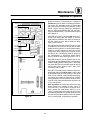
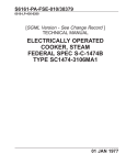
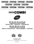
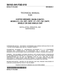
S6163-CY-FSE-010
REVISION 1
TECHNICAL MANUAL
FOR
OVEN, BLODGETT
MODEL HV100-EM
INSTALLATION, OPERATION, AND MAINTENANCE
PROCEDURES
SUPERSEDURE NOTICE: THIS MANUAL SUPERSEDES S6163-CY-FSE-010,
DATED 15 OCTOBER 2009, AND ALL CHANGES THERETO.
DISTRIBUTION STATEMENT A: APPROVED FOR PUBLIC RELEASE; DISTRIBUTION IS UNLIMITED.
PUBLISHED BY DIRECTION OF COMMANDER, NAVAL SEA SYSTEMS COMMAND
*0910LP1117373*
19 JUL 2012
TITLE-1 / (TITLE-2 Blank)@@FIpgtype@@TITLE@@!FIpgtype@@
@@FIpgtype@@TITLE@@!FIpgtype@@
TECHNICAL MANUAL CERTIFICATION SHEET
CERTIFICATION APPLIES TO:
NEW MANUALS
REVISION
CHANGE
APPLICABLE TMINS/PUB. NO.
PUBLICATION DATE (day, month, year)
READING GRADE LEVEL (RGL)
S6163-CY-FSE-010 REV 1
19 JULY 2012
9
TITLE
TECHNICAL MANUAL FOR OVEN, BLODGETT, MODEL HV100-EM; INSTALLATION,
OPERATION, AND MAINTENANCE PROCEDURES; REVISION 1
TMCR/TMSR/SPECIFICATION NUMBER
TMCR NO. NDMS-050065-000
CHANGES AND REVISIONS:
PURPOSE
REVISION 1 TECHNICAL MANUAL UPDATED WITH THE MOST RECENT VENDOR
PUBLICATION, MODEL HV100-EM.
EQUIPMENT ALTERATION NUMBERS INCORPORATED
N/A
TMDER/ACN NUMBERS INCORPORATED
N/A
Continued on additional pages as needed.
CERTIFICATION STATEMENT
This is to certify that responsible Navy activities have reviewed the above identified document for
acquisition compliance, technical coverage and printing quality. This form is for internal
Government management use only and does not imply contractual approval or acceptance of the
technical manual by the Government nor does it relieve the contractor of any responsibilities for
delivering the technical manual in accordance with the contract requirements.
ACQUISITION
NAME
SIGNATURE
John G Coceano
TECHNICAL
NAME
SIGNATURE
JAMES BRECHKA
PRINTING
NAME
RELEASE
Barry Bengel
NAVSEA 4160/8 (Rev 7-2003)
SIGNATURE
ORGANIZATION
CODE
DATE
NSWCCD-SSES
944
17JUL12
ORGANIZATION
CODE
DATE
NSWCCD-SSES
974
26JUL12
ORGANIZATION
CODE
DATE
NSWCCD-SSES
944
8 AUG 12
S6163-CY-FSE-010
19 July 2012
IDENTIFYING TECHNICAL PUBLICATION SHEET FOR
COMMERCIAL MANUAL
This manual supersedes S6163-CY-FSE-010, dated 15 October 2009, and all changes thereto.
1. PURPOSE: This technical publication sheet is issued for the purpose of identifying and authorizing
the following commercial manual for Navy use.
Manufacturer:
G.S. Blodgett Corporation
DBA Blodgett Oven Co.
44 Lakeside Ave.
Burlington, VT 05401-5242
Cage 07695
Purchase Order or Contract No.: N/A
Requisition No.: N/A
Equipment: HV-100EM Convection Oven with Moisture
National Stock Number: 0910-LP-111-7373
Title: Technical Manual for Oven, Blodgett, Model HV100-EM; Installation, Operation, and
Maintenance Procedures
Additional Identification: N/A
Date: 19 July 2012
2. ADDITIONAL COPIES: Additional copies are available from the Naval Logistics Library (NLL).
3. FILE LOCATION: The above-described commercial manual is filed in ________________________.
4. AUTHORITY NOTICE AND DISTRIBUTION STATEMENT:
Published by direction of Commander, Naval Sea Systems Command.
Distribution Statement A: Distribution Approved for public release, distribution is unlimited.
FOR UNCLASSIFIED MANUALS
NOTICE: Reproduction for non-military use of the information or illustration in this publication is not
permitted. The policy for military use reproduction is established in OPNAVINST 5510.1B.
This material may be reproduced by or for the U.S. Government pursuant to the rights acquired under
Article 39 of Newport News Shipbuilding Purchase Order DoD Contracts Appendix A dated June 2010.
D-4
@@FIpgtype@@BLANK@@!FIpgtype@@
S6163-CY-FSE-010
RECORD OF REVISIONS
REV NO.
DATE
0
1
15 OCT 2009
19 JUL 2012
TITLE AND/OR BRIEF DESCRIPTION/PREPARING ACTIVITY
ORIGINAL PUBLICATION OF MANUAL.
UPDATED TO MOST RECENT BLOGETT OVEN TECHNICAL
MANUAL.
FOR OPTIMAL VIEWING OF THIS TECHNICAL MANUAL THE PAGE LAYOUT IN ADOBE ACROBAT
READER SHOULD BE SINGLE PAGE. CONTINUOUS PAGE DISPLAY CAN CAUSE PROBLEMS WITH
LINK REFERENCES AND THE BOOKMARKS.
RECORD OF REVISIONS-1 / (RECORD OF REVISIONS-2 Blank)
RECORD OF REVISIONS-2
@@FIpgtype@@BLANK@@!FIpgtype@@
S6163-CY-FSE-010
FOREWORD
This technical manual provides installation, operation, and maintenance procedures for the Blodgett Oven,
Model HV-110E. This technical manual is intended for guidance of and use by personnel operating and maintaining the equipment described herein.
This manual consists of four chapters as follows:
• Introduction
• Installation
• Operation
• Maintenance
Ships, training activities, supply points, depots, Naval Shipyards and Supervisors of Shipbuilding are
requested to arrange for the maximum practical use and evaluation of NAVSEA technical manuals. All errors,
omissions, discrepancies and suggestions for improvement to NAVSEA technical manuals shall be forwarded to:
COMMANDER
CODE 310 TMDERs
NAVSURFWARCENDIV NSDSA
4363 MISSILE WAY BLDG 1389
PORT HUENEME, CA 93043-4307
on NAVSEA/SPAWAR Technical Manual Deficiency/Evaluation Report (TMDER), NAVSEA form 4160/1. All
feedback comments shall be thoroughly investigated and originators will be advised of action resulting therefrom. One copy of NAVSEA form 4160/1 is at the end of each separately bound technical manual 8-1/2 x 11
inches or larger. Copies of NAVSEA form 4160/1 may be requisitioned from the Naval Systems Data Support
Activity Code 310 at the above address. Users are encouraged to transmit deficiency submittals via the Naval
Systems Data Support Activity Web site located at:
https://mercury.tdmis.navy.mil/def_external/pubsearch.cfm
FOREWORD-1
S6163-CY-FSE-010
SAFETY SUMMARY
GENERAL SAFETY NOTICES
The following general safety notices supplement the specific warnings and cautions appearing elsewhere
in this manual. They are recommended precautions that must be understood and applied during operation and
maintenance of the equipment covered herein. Should situations arise that are not covered in the general or specific safety precautions, the commanding officer or other authority will issue orders as deemed necessary to cover
the situation. No work shall be undertaken on energized equipment or circuits until approval of the commanding
officer is obtained, and then only in accordance with Naval Ships’ Technical Manual (NSTM) S9086-KC-STM010/Chapter 300.
DO NOT REPAIR OR ADJUST ALONE
Under no circumstances shall repair or adjustment of energized equipment be attempted alone. The immediate presence of someone capable of rendering first aid is required. Before making adjustments, be sure to protect against grounding. If possible, adjustments should be made with one hand, with the other hand free and clear
of equipment. Even when power has been removed from equipment circuits, dangerous potentials may still exist
due to retention of charges by capacitors. Circuits must be grounded and all capacitors discharged prior to
attempting repairs. Equipment should be deenergized and properly tagged out according to the ship’s Standard
Operating Procedures.
TEST EQUIPMENT
Make certain test equipment is in good condition. If a metal-cased test meter must be held, ground the case
of the meter before starting measurement. Do not touch live equipment or personnel working on live equipment
while holding a test meter. Do not ground any measuring devices; these devices should not be held when taking
measurements.
INTERLOCKS
Interlocks are provided for safety of personnel and equipment and should be used only for the purpose
intended. They should not be battle shorted or otherwise modified except by authorized maintenance personnel.
Do not depend solely upon interlocks for protection. Whenever possible, disconnect power at the power distribution source.
MOVING EQUIPMENT
Personnel shall remain clear of moving equipment. If equipment requires adjustment while in motion, a
safety watch shall be posted. The safety watch shall be qualified to administer CPR, have a full view of the
operations being performed, and have immediate access to controls capable of stopping equipment motion.
FIRST AID
An injury, no matter how slight, shall never go unattended. Always obtain first aid or medical attention
immediately, and file an injury report in accordance with OPNAVINST 5102.1 series, subj: Mishap Investigation
and Reporting.
ii
S6163-CY-FSE-010
SAFETY SUMMARY - Continued
RESUSCITATION
Personnel working with or near high voltage shall be familiar with approved methods of resuscitation.
Should someone be injured and stop breathing, begin resuscitation immediately. A delay could cost the victim’s
life. Resuscitation procedures shall be posted in all electrically hazardous areas.
FINGER RINGS/JEWELRY
Finger rings have caused many serious injuries. Remove rings, watches and other metallic objects that may
cause shock or burn hazards. Unless specifically allowed by shop safety procedures, remove finger rings and
jewelry during all maintenance activity.
COMPRESSED AIR
Do not use compressed air for general cleaning. Compressed air may be used only for cleaning of electric
motors. Use of compressed air can create an environment of propelled particles. Do not direct air streams toward
self or other personnel. Air pressure shall be reduced to less than 30 psig and used with effective chip guarding
and personal protective equipment.
DANGEROUS PRESSURES
Care must be taken to ensure that all pressurized connections are proper and tight. All system components
must be compatible with pressure applied. During testing protect personnel with safety shields or keep them at
a distance sufficient to prevent injury.
SPRING LOADED MECHANISM
A spring loaded mechanism can cause injury if released in an uncontrolled manner. Always take extra care
when disassembling this type of mechanism.
DO NOT SERVICE OR ADJUST ALONE
Do not attempt internal service or adjustment of equipment unless another person capable of rendering aid
and resuscitation is present.
LIFTING AND HANDLING
Use adequate personnel or appropriately rated lifting and handling devices to move these components.
LOCKOUT/TAGOUT
Personnel shall be aware of the hazards associated with unguarded machinery parts, capacitors, gaseous
and wet pipe systems, spring loaded devices, etc. Lockout/tagout the energy source prior to performing maintenance, adjustments or other procedures that would bypass safety guards, barriers or otherwise expose personnel
to hazardous energy sources. Any equipment, machine or process that could unexpectedly energize, startup or
release energy will be equipped with a means to lockout/tagout the energy source. Electrical, pneumatic and
iii
S6163-CY-FSE-010
SAFETY SUMMARY - Continued
hydraulic controls shall be tagged DANGER – DO NOT OPERATE prior to maintenance procedures. Lockout/
tagout procedures shall be in accordance with current shipboard instructions.
APPROVED LUBRICANTS
Use only approved lubricants as specified in this manual. Other lubricants are inadequate and can cause
failure of system components, resulting in personnel injury and equipment damage.
OPERATOR TRAINING
Operators must be familiar with all controls, indicators and component parts of the equipment and all
Warnings and Cautions before performing any operation or maintenance.
HAZARDOUS MATERIALS
Warnings for hazardous material are designed to warn personnel of hazards associated with such items
when they come in contact with them during actual use. For each hazardous material used, a Material Safety Data
Sheet (MSDS) is required to be provided and available for review by users. Consult your local safety and health
staff concerning any questions on hazardous chemicals, MSDSs, personal protective equipment requirements and
handling and emergency procedures.
GENERAL PRECAUTIONS
The following general precautions are to be observed at all times.
1.
Install and ground all electrical components associated with this system/equipment in accordance
with applicable Navy regulations and approved shipboard practices.
2.
Ensure that all maintenance operations comply with Navy Occupational Safety and Health
(NAVOSH) Program Manual for Forces Afloat, OPNAVINST 5100.19 series.
3.
Observe precautions set forth in NSTM S9086-KC-STM-010/Chapter 300 with respect to electrical
equipment and circuits.
4.
Ensure that protective guards and shutdown devices are properly installed and maintained around
rotating parts of machinery and high voltage sources.
5.
Do not wear loose clothing while working around rotating parts of machinery.
6.
Ensure that special precautionary measures are employed to prevent applying power to the system/
equipment any time maintenance work is in progress.
7.
Do not make any unauthorized alterations to equipment or components.
8.
Before working on electrical system/equipment, use the correct tag out procedure and check with
voltmeter to ensure that system is not energized.
9.
Consider all circuits not known to be ″dead,″ ″live″ and dangerous at all times.
10. When working near electricity, do not use metal rules, flashlights, metallic pencils, or any other
objects having exposed conducting material.
11. Deenergize all equipment before connecting or disconnecting meters or test leads.
iv
S6163-CY-FSE-010
SAFETY SUMMARY - Continued
12. When connecting a meter to terminals for measurement, use range higher than expected voltage.
13. Before operating equipment or performing any tests or measurements, ensure area is dry of water or
other liquid conductive material and that frames of all motors and starter panels are securely
grounded.
14. Ensure that area is well-ventilated when using cleaning compound or solvent. Avoid prolonged
breathing of fumes and compound or solvent contact with skin or eyes.
v / (vi Blank)
vi
@@FIpgtype@@BLANK@@!FIpgtype@@
HVĆ100EM
CONVECTION OVEN WITH MOISTURE
INSTALLATION - OPERATION - MAINTENANCE
BLODGETT OVEN COMPANY
www.blodgett.com
44 Lakeside Avenue, Burlington, Vermont 05401 USA Telephone (802) 658Ć6600 Fax: (802)864Ć0183
PN 51702 Rev F (11/10)
2010 - G.S. Blodgett Corporation
THE REPUTATION YOU CAN COUNT ON
For over a century and a half, The Blodgett Oven Company has been building
ovens and nothing but ovens. We've set the industry's quality standard for all
kinds of ovens for every foodservice operation regardless of size, application
or budget. In fact, no one offers more models, sizes, and oven applications
than Blodgett; gas and electric, fullĆsize, halfĆsize, countertop and deck, conĆ
vection, Cook'n Hold, CombiĆOvens and the industry's highest quality Pizza
Oven line. For more information on the full line of Blodgett ovens contact your
Blodgett representative.
IMPORTANT
WARNING: IMPROPER INSTALLATION, ADJUSTMENT, ALTERATION, SERVICE OR
MAINTENANCE CAN CAUSE PROPERTY DAMAGE, INJURY OR DEATH. READ THE
INSTALLATION, OPERATING AND MAINTENANCE INSTRUCTIONS THOROUGHLY
BEFORE INSTALLING OR SERVICING THIS EQUIPMENT
FOR YOUR SAFETY
Do not store or use gasoline or other flammable vapors or liquids in the vicinity
of this or any other appliance.
The information contained in this manual is important for the proper installation,
use, and maintenance of this oven. Adherence to these procedures and instrucĆ
tions will result in satisfactory baking results and long, trouble free service.
Please read this manual carefully and retain it for future reference.
Errors: Descriptive, typographic or pictorial errors are subject to correction. SpecificaĆ
tions are subject to change without notice.
Model:
Your Service Agency's Address:
Serial Number
Your appliance was installed by
Your oven's installation was checked by
Table of Contents
Introduction
Oven Description and Specifications . . . . . . . . . . . . . . . . . . . . . . . . . . . . . . . . . . . . . . . . . . . . . . . . . . . 2
Installation
Agency Approvals . . . . . . . . . . . . . . . . . . . . . . . . . . . . . . . . . . . . . . . . . . . . . . . . . . . . . . . . . . . . . . . . . . . 3
Oven Location and Shipping . . . . . . . . . . . . . . . . . . . . . . . . . . . . . . . . . . . . . . . . . . . . . . . . . . . . . . . . . . 4
Ventilation . . . . . . . . . . . . . . . . . . . . . . . . . . . . . . . . . . . . . . . . . . . . . . . . . . . . . . . . . . . . . . . . . . . . . . . . . . 5
Oven Assembly . . . . . . . . . . . . . . . . . . . . . . . . . . . . . . . . . . . . . . . . . . . . . . . . . . . . . . . . . . . . . . . . . . . . . 6
Supply Water and Plumbing . . . . . . . . . . . . . . . . . . . . . . . . . . . . . . . . . . . . . . . . . . . . . . . . . . . . . . . . . 10
Electrical Supply . . . . . . . . . . . . . . . . . . . . . . . . . . . . . . . . . . . . . . . . . . . . . . . . . . . . . . . . . . . . . . . . . . . . 11
Operation
MenuSelect Control . . . . . . . . . . . . . . . . . . . . . . . . . . . . . . . . . . . . . . . . . . . . . . . . . . . . . . . . . . . . . . . 12
Maintenance
Spray Bottle Operating Procedure . . . . . . . . . . . . . . . . . . . . . . . . . . . . . . . . . . . . . . . . . . . . . . . . . . . . 18
Cleaning and Preventive Maintenance . . . . . . . . . . . . . . . . . . . . . . . . . . . . . . . . . . . . . . . . . . . . . . . . . 19
Replacement Parts . . . . . . . . . . . . . . . . . . . . . . . . . . . . . . . . . . . . . . . . . . . . . . . . . . . . . . . . . . . . . . . . . . 21
Second Level Programming . . . . . . . . . . . . . . . . . . . . . . . . . . . . . . . . . . . . . . . . . . . . . . . . . . . . . . . . . . 29
Troubleshooting . . . . . . . . . . . . . . . . . . . . . . . . . . . . . . . . . . . . . . . . . . . . . . . . . . . . . . . . . . . . . . . . . . . . 31
Sequence of Operation . . . . . . . . . . . . . . . . . . . . . . . . . . . . . . . . . . . . . . . . . . . . . . . . . . . . . . . . . . . . . . 33
Component Resistance Readings . . . . . . . . . . . . . . . . . . . . . . . . . . . . . . . . . . . . . . . . . . . . . . . . . . . . 35
Probe Ohms Chart . . . . . . . . . . . . . . . . . . . . . . . . . . . . . . . . . . . . . . . . . . . . . . . . . . . . . . . . . . . . . . . . . . 36
Introduction
Oven Description and Specifications
Blodgett ovens are quality produced using highĆ
grade stainless steel with first class workmanship.
Ease of operation is guaranteed through the simĆ
ple arrangement of the controls. Graphic symbols
make the appliance easy for even inexperienced
kitchen staff to operate. The Cool Down mode, alĆ
lows the oven cavity to cool down rapidly with the
door opened.
The multiple speed fan, which is guarded against
accidental finger contact, is driven by a quiet and
powerful motor. The condenser draws out excess
moisture from the appliance. Condensation and
waste water, which result during hydro cooking
and cleaning, are continuously drained.
Cleaning is kept to a minimum. The interior is
sprayed with a selfĆacting cleaning solution which
interacts with humidity to easily remove crusts and
stains. The oven is designed for easy care and is
welded water tight so that the internal cooking
cavity may be rinsed with a hose after the cleaning
process.
The use of high quality insulation impedes excesĆ
sive heat radiation and saves energy.
The HVĆ100EM has legs which adapt easily to
slightly uneven surfaces.
The practical oven doors, with viewing windows,
have a wide swing radius and handle which can be
operated easily, even with wet or greasy hands.
ELECTRIC SPECIFICATIONS
Voltage
440
Hz
60
kW
15
Phase
3
Max Load (amps)
L1
L2
L3
20
18
18
Motor
1/2 HP 208Ć240VAC, 50/60 Hz
PLUMBING SPECIFICATIONS
WATER
Supply Water Pressure
30 PSI (207 kPa) minimum
50 PSI (345 kPa) maximum
Water Connection
3/4" garden hose - Cold water only
Internal Water Pressure
Regulator Setting
Preset to 20 PSI (138 kPa)
Minimum Requirements
TDS - less than 100 parts per million
Flow rate of 4 GPH
Total Hardness - 80Ć120 parts per million
Chlorides - less than 30 parts per million
Chlorine - 0 parts per million
pH Factor - 7.0Ć8.0
DRAINAGE
Drain Type
Atmospheric Vented Drain
Drain Connection
1" NPT Male
2
Installation
Agency Approvals
THE INSTALLATION INSTRUCTIONS CONĆ
TAINED HEREIN ARE FOR THE USE OF QUALIĆ
FIED INSTALLATION AND SERVICE PERSONNEL
ONLY. INSTALLATION OR SERVICE BY OTHER
THAN QUALIFIED PERSONNEL MAY RESULT IN
DAMAGE TO THE OVEN AND/OR INJURY TO
THE OPERATOR.
U.S. and Canadian Installations
Reference: National Electrical Code, ANSI/NFPA
70-Latest Edition and/or Canadian Electrical
Code CSA C22.1 as applicable.
This equipment is to be installed in compliance
with the Basic Plumbing Code of the Building OffiĆ
cials and Code Administrators International Inc.
(BOCA) and the Food Service Sanitation Manual of
the Food and Drug Administration (FDA).
Qualified installation personnel are individuals, a
firm, a corporation, or a company which either in
person or through a representative are engaged
in, and are responsible for:
Appliance is to be installed with backflow prevenĆ
tion in accordance with applicable federal, provĆ
ince and local codes.
The installation or replacement of gas piping.
The connection, installation, repair or servicing
of equipment.
The installation of electrical wiring from the elecĆ
tric meter, main control box or service outlet to
the electric appliance.
General Export Installations
Installation must conform with Local and National
installation standards. Local installation codes and/
or requirements may vary. If you have any questions
regarding the proper installation and/or operation of
your appliance, please contact your local distributor.
If you do not have a local distributor, please call
Blodgett Combi at 0011Ć802Ć860Ć3700.
Qualified installation personnel must be experiĆ
enced in such work, be familiar with all precauĆ
tions required and have complied with all requireĆ
ments of state or local authorities having
jurisdiction.
3
Installation
Oven Location and Shipping
OWNER'S RESPONSIBILITIES
NOTE: The following parts are shipped with the
oven.
Installation responsibilities prior to service
startup inspection
Part #
Description
R10955
Cleaning spray bottle
1
33136
Power cord
2
52723
Drain elbow connection
2
52724
5' drain hose
1
R2207
Hose clamp
4
R10889
10' water hose
1
52728
3' water hose
1
OVEN LOCATION
52596
Water manifold
1
The well planned and proper placement of your
oven will result in long term operator convenience
and satisfactory performance.
52713
Utility box
1
52734
Utility line retainer bracket
1
Certain minimum clearances must be maintained
between the oven and any combustible or nonĆ
combustible construction.
52715
Vent extension bracket
1
52349
Cavity vent extension
1
52648
4" vent extension hose
1
33196
Seismic legs, set
1
1/2Ć13 x 3/4" stacking
bolts
4
Kit, set of ship deck legs
1
You are entitled to a free startĆup inspection serĆ
vice by our factory ASAP. Before a factory repreĆ
sentative arrives to perform a startup procedure,
the owner must already have satisfied the followĆ
ing requirements.
1. Oven(s) are uncrated, stacked (if applies) and
put in place.
NOTE: Please refer to Leg Attachment and
Stacking.
Maximum shelf loading - 60 lbs (27.3 Kg)
Oven body sides - 0" (0cm)
Oven body back - 6" (152.4cm)
In addition, the following clearances are recomĆ
mended for servicing.
315
Oven body sides - 12" (30cm)
Oven body back - 12" (30cm)
34907
SHIPPING
4
Qty.
Installation
Ventilation
VENTILATION
will not be covered by the Manufacturer's
warranty.
The necessity for a properly designed and inĆ
stalled ventilation system cannot be over emphaĆ
sized. The ventilation system will allow the unit to
function properly while removing unwanted vaĆ
pors and products of combustion from the operatĆ
ing area.
When installed in the Commonwealth of MassaĆ
chusetts, this appliance must be interlocked with
the hood exhaust system so that the appliance
may be operated only when the hood exhaust sysĆ
tem is running.
U.S. and Canadian Installations
The appliance must be vented with a properly deĆ
signed mechanically driven exhaust hood. The
hood should be sized to completely cover the
equipment plus an overhang of at least 6" (15 cm)
on all sides not adjacent to a wall. The capacity of
the hood should be sized appropriately and proviĆ
sions made for adequate makeup air.
Refer to your local ventilation codes. In the abĆ
sence of local codes, refer to the National ventilaĆ
tion code titled, Standard for the Installation of
Equipment for the Removal of Smoke and Grease
Laden Vapors from Commercial Cooking EquipĆ
ment", NFPAĆ96Ć Latest Edition.
General Export Installations
WARNING!!
Installation must conform with Local and National
installation standards. Local installation codes
and/or requirements may vary. If you have any
questions regarding the proper installation and/or
operation of your unit, please contact your local
distributor. If you do not have a local distributor,
please call Blodgett at 0011Ć802Ć860Ć3700.
Failure to properly vent the oven can be
hazardous to the health of the operator;
and will result in operational problems,
unsatisfactory baking, and possible damĆ
age to the equipment. Damage sustained
as a direct result of improper ventilation
5
Installation
Oven Assembly
POSSIBLE LEG BOLTING PATTERNS
There are two leg mounting options. See Figure 1.
36.19 (2 PLACES)
27.94 (2 PLACES)
.875 (8 PLACES)
35.00 (2 PLACES)
35.00 (2 PLACES)
26.75 (2 PLACES)
36.19 (2 PLACES)
.313
(8 PLACES) 2.50
(4 PLACES)
See page 4 for
part numbers
Figure 1
6
3.50 (4 PLACES)
.56 HOLE
(4 PLACES)
Installation
Oven Assembly
LEG ATTACHMENT
1. Align the threaded stud on the right front leg
to the bolt h
ā oleā locatedāā ināā tā heāā bottom c
ā orner of
the oven. Turn the leg clockwise and tighten to
the nearest full turn.
2. Align the leg plate holes with the bolt holes.
Figure 4
6. Tip the oven up on the newly installed front
legs. ā
7. Repeat āthe above steps for the right rear leg.
Install the retainer bracket before securing
the right rear leg. Align the holes in the retainĆ
er bracket to the holes in the right leg plate.
See Figure 5.
8. Secure the leg and retainer bracket with the
two 3/4" bolts provided.
Figure 2
3. Install the utility box before securing the
right front leg. Align the holes in the utility box
bracket to the holes in the leg plate. See
Figure 3.
4. Secure the leg and utility box with the two 3/4"
bolts provided.
Retainer
Bracket
Utility Box
Figure 3
Figure 5
5. Repeat steps 1, 2 and 4 with the left front leg.
9. Install the left rear leg.
10. Tip the oven onto the feet and place in posiĆ
tion. Level the oven by screwing the adjustĆ
able feet in or out as necessary.
7
Installation
Oven Assembly
Electrical
1. Remove the two screws from above and beĆ
low the control panel. Slide the panel out to acĆ
cess the terminal blocks. Refer to page 7.
OVEN STACKING
1. Place the upper oven on top of the lower oven.
2. Bolt the two ovens together from behind using
the stacking brackets.
UTILITY CONNECTIONS
Transformer End Stop
Shorting
Jumper
NOTE: Refer to Figure 6 for location of utility conĆ
nection on the back of the ovens.
Ground Lug
Terminal
Cavity
Vents
Terminal
Block
1/4 Swivel
Elbow
1/4 Straight
Fitting
Figure 7
2. Connect the power cord to the top unit. Run
the cord down the back of the oven, using the
provided strain relief.
3. Then route the cord under the oven, supportĆ
ing it on the retainer bracket on the rear right
leg. Connect to the top right receptacle on the
utility box at the front of the oven. See
Figure 8.
4. Connect the power cord to the bottom unit.
Run the cord down the back of the oven, using
the provided strain relief.
5. Then route the cord under the oven, supportĆ
ing it on the retainer bracket on the rear right
leg. Connect to the bottom right receptacle on
the utility box at the front of the oven. See
Figure 8.
Drains
Water
Manifold
Figure 6
8
Installation
Oven Assembly
3. Attach the supplied elbow assembly to the
oven drain outlet on both units.
4. Attach the supplied drain hose to the top unit.
Cut for proper length into the funnel drain. Use
the remaining piece of hose for the bottom
oven if necessary. See Figure 6 for location of
drain connection on back of ovens.
Top Oven
Electric
Cord
Bottom Oven
Electric Cord
Utility
Box
Cavity Vent Extension
1. Attach the cavity vent extension using the siliĆ
con tubing and two clamps provided.
2. Remove the existing screw and use it to seĆ
cure the top section in the bracket. The tabs
on the bracket will deflect for a secure fit.
Retainer
Bracket
Figure 8
Utility Supply Connection
6. Reattach the right side panels once the electriĆ
cal connections are complete.
1. Connect incoming power from the ship to the
electrical connection on the utility box underĆ
neath the oven. See Figure 10.
2. Connect the cold water supply from the ship
to the incoming water connection on the utility
box underneath the oven. A 10' water hose is
supplied for your convenience. See Figure 10.
Water and Drain
1. Attach the water manifold to the back of the
ovens.
2. Attach the short water hose from the water
manifold to the utility box underneath the
oven.
Incoming
Electrical
Supply
Utility
Box
Incoming
Water
Supply
Short
Hose
Water
Manifold
Figure 10
Figure 9
9
Installation
Supply Water and Plumbing
WATER CONNECTION
Specific water/drain connection for City of Los
Angeles
NOTE: Must use COLD WATER ONLY.
A shut off valve is to be provided adjacent to the
oven.
WARNING!!
Operating the appliance without a water
regulator installed will invalidate your warĆ
ranty.
This product must be installed by a licensed
Plumber or Gas Fitter when installed within the
Commonwealth of Massachusetts.
DRAIN CONNECTION
The drain should be run to an open floor drain
avoiding flexible hose that could sag and allow
trapped water to accumulate.
10
1. Each drain line from the appliance shall be
routed without dips or sags to terminate above
the flood level rim of an approved indirect waste
receptor.
2. The appliance shall be installed in accordance
with the manufacturer's printed instructions
and the LAPC and LAMC, 1999 editions.
3. A backflow protection device may be required
by local codes. If so, install on the potable water
system directly ahead of the appliance. The
backflow protection device shall be any of the
following: an approved pressure type vacuum
breaker installed at least 12" above the highest
point of use, a double check valve backflow preĆ
venter or a reduced pressure principal backflow
preventer.
Installation
Electrical Supply
NOTE: Electrical connections must be performed
by a qualified installer only.
Before making any electrical connections to these
appliances, check that the power supply is adeĆ
quate for the voltage, amperage, and phase reĆ
quirements stated on the rating name plate
mounted on the appliance.
The circuit breaker that is used to provide power
to this appliance must have a minimum of .076"
(3mm) contact spacing. The circuit breaker must
meet all Local and National installation standards.
NOTE: Disconnect the power supply to the apĆ
pliance before servicing.
WARNING!!
Improper installation may invalidate your
warranty.
A strain relief for the power supply cord is provided.
All appliances must be installed in accordance
with Local or National Electrical codes.
A wiring schematic is located in the slide out panel.
Figure 11
11
WARNING!!
If the supply cord is damaged, it must be
replaced by a special cord or assembly
available from the manufacturer or its serĆ
vice agent.
Operation
MenuSelectt Control
CONTROL DESCRIPTION
1. START/STOP KEY Ć press to start, cancel or
pause the bake
2. COOL DOWN KEY Ć initiates oven cool down
cycle
3. BAKE MORE KEY Ć press at the end of a bake
cycle to add additional bake time in one minĆ
ute increments.
4. DISPLAY Ć displays time or temperature and
other information related to oven function and/
or programming.
5. NAVIGATION PAD Ć used to enter set points,
time, and programmable settings. Also used
to select the programmed product.
6. TEMP KEY Ć used to set or change the bake
temperature
7. TIME KEY Ć used to set or change the bake
time.
8. COMBI KEY Ć press to enter combi mode
9. STEAM KEY Ć press to enter steam mode
10. HOT AIR KEY Ć press to enter hot air mode
11. RETHERM KEY Ć press to enter retherm
mode, this mode uses steam to reheat frozen
or precooked product. Retherm has a temperĆ
ature limit of 250Ć300F.
12. STEAM ON DEMAND KEY Ć used to initiate
steam injection cycle
13. PROBE KEY Ć press to use core probe cooking
14. FAN KEY Ć press to select the fan speed
15. LIGHT KEY Ć press to turn the lights on and off.
16. VENT KEY Ć press to manually open and close
the oven vent
17. PROGRAM KEY Ć press to enter product proĆ
gramming and save programmed settings.
18. ESCAPE KEY Ć press to back up one step durĆ
ing programming
19. MAINTENANCE KEY Ć press to enter manager
programming and save programmed settings
20. ALPHA/NUMERIC KEYPAD Ć used to program
recipes.
21. POWER KEY Ć used to place control in and out
of standby mode.
22. CORE PROBE CONNECTION Ć plug core temĆ
perature probe in here when using probe
cooking
2
1
3
4
5
6
7
8
9
11
10
12
13
14
16
15
19
17
20
18
21
22
23
24
Figure 12
12
Operation
MenuSelectt Control
23. CIRCUIT BREAKER - Used to turn power to
the unit on or off.
24. USB PORT - Used to download programĆ
ming information from a USB drive
OVEN STARTUP
1. Be sure the circuit breaker is pushed in. The
display flashes OFF PRESS POWER KEY TO
START.
NOTE: If the real time clock and auto wake up
functions are enabled the display
reads PRESS POWER KEY TO START
AUTO START.
2. Press the POWER KEY (21). The display reads
PREHEAT and the oven heats to the last manuĆ
al set temperature in the hot air mode. The disĆ
play flashes READY / IDLE and the alarm beeps
5 times when the oven is at temperature and
ready to bake.
MANUAL COOKING
1. Press the arrows on the NAVIGATION PAD (5)
until the display reads MANUAL.
2. Press the TIME KEY (7). Use the either the arĆ
rows or the alpha/numeric keypad to enter the
desired bake time. Press OK on the NAVIGAĆ
TION PAD (5) to set the bake time.
NOTE: Time is set in one minute increments
using the arrows. To set time in less
than one minute increments use the alĆ
pha/numeric keypad.
3. Press the TEMP KEY (6). Use the arrows or the
alpha/numeric keypad to enter the desired
bake temperature. Press OK to set the bake
temperature. The oven preheats to the new
temperature.
NOTE: Temperature is set in 5 degree increĆ
ments using the dial. To set time in less
than 5 degree increments use the alĆ
pha/numeric keypad.
4. Press the desired mode key, combi, steam,
hot air or retherm.
If Combi or Retherm are selected, use the arĆ
rows or the alpha/numeric keypad to enter the
desired percentage of steam.
NOTE: Retherm has a temperature limit of
250Ć300_F.
13
5. When the display flashes READY / IDLE, open
the doors. Load the product.
6. Press the START/STOP KEY (1) to begin the
bake cycle. The timer counts down and the
display alternates between the cooking mode
and the name of the product.
PROGRAMMED COOKING
1. Press the down arrow key until the name of
the product is highlighted, or use the alpha/
numeric keypad to enter a recipe number.
Press OK to select. The oven preheats to the
programmed temperature in the correct cookĆ
ing mode. The display flashes READY / IDLE
and the alarm beeps 5 times when the oven is
at temperature and ready to bake.
2. Open the doors. Load the product.
3. Press the START/STOP KEY (1) to begin the
bake cycle. The timer counts down and the
display alternates between the cooking mode
and the name of the product.
PROBE COOKING
1. Press the PROBE key (13) to select the probe
mode. The display reads CORE PROBE
COOK & HOLD. Use the arrowsl to select eiĆ
ther YES or NO. Press OK to select.
If YES is selected, Cook & Hold has been enĆ
abled. In the Cook & Hold mode, the oven cavĆ
ity lowers to the product pull temperature as
the product cooks.
If NO is selected, Cook & Hold has not been
enabled the cavity maintains the cook temperĆ
ature.
2. Use the arrows to enter the desired product
pull temperature in the display. Press OK to
save the pull temperature.
3. Press the TEMP KEY (6). Use the arrows or the
alpha/numeric keypad to enter the desired
bake temperature. Press OK to set the bake
temperature. The oven preheats to the new
temperature.
NOTE: Temperature is set in 5 degree increĆ
ments using the dial. To set time in less
than 5 degree increments use the alĆ
pha/numeric keypad.
Operation
MenuSelectt Control
4. Press the desired mode key, combi, steam,
hot air or retherm.
If Combi or Retherm are selected, use the arĆ
rows or the alpha/numeric keypad to enter the
desired percentage of steam.
NOTE: Retherm has a temperature limit of
250Ć300_F.
5. Insert the core probe into the product. Load
product into the oven and close the door. Be
sure that the terminal end of the core probe is
outside of the oven and clear of the door.
6. Connect the core probe to the PROBE CONĆ
NECTION (22) at the bottom of the control.
NOTE: Do not connect the probe before the
cook mode has been selected.
7. The display gives the actual core probe temĆ
perature as well as the oven set temperature.
8. When the product reaches the pull temperaĆ
ture the buzzer sounds.
9. Press the START/STOP KEY (1) to silence the
buzzer.
If using Cook & Hold - The cavity temperaĆ
ture continues to drop to the product pull temĆ
perature and the display counts up, telling the
operator how long the product has been held.
Disconnect the core probe and remove the
product when ready.
If not using Cook & Hold - The cavity reĆ
mains at the cook temperature. The display
does not count up. Disconnect the core probe
and remove the product when the buzzer
sounds.
DURING ANY COOK CYCLE
Steam On Demand
While in the Hot Air, Combi or retherm modes, the
unit can be set to steam for a timed period of up
to 20 minutes. At the end of the timed cycle the unit
reverts back to the original setting. Steam On DeĆ
mand can be used at any time during the cook
cycle.
1. Press the STEAM ON DEMAND KEY (12).
2. Use the arrows or the alpha/numeric keypad
to enter the desired steam on demand time.
Press OK to initiate Steam on Demand cycle.
14
NOTE: Steam on Demand time is set in one
minute increments using the arrows.
To set time in less than one minute inĆ
crements use the alpha/numeric keyĆ
pad.
3. The Steam on Demand LED flashes until the
steam time has expired.
Venting Moisture from the Oven Cavity
1. Press the VENT KEY (16). This manually
opens the vent until the key is pressed again
to close it.
Pause a Bake Cycle
1. To pause a cook cycle, press the START/
STOP KEY (1). The LED on the start/stop key
flashes. The bake cycle will pause until the key
is pressed again.
Cancel a Cook Cycle
1. To cancel the cook cycle, press and hold the
START/STOP KEY (1).
AT THE END OF ANY COOK CYCLE
1. An alarm sounds, the display reads DONE.
2. If more bake time is desired, press the BAKE
MORE KEY (3). This will add an additional one
minute of time for each press of the key.
3. When you are satisfied with the bake, press
the START/STOP KEY (1) to silence the alarm.
Open the door to remove the product.
OVEN SHUTDOWN
1. Press the COOL DOWN KEY (2). The display
reads AUTO COOL DOWN ACTUAL TEMP. To
speed up the cool down process, open the
doors and press the VENT KEY (16) to open
the vent.
2. When the oven has cooled down, the display
reads OFF PRESS POWER KEY TO START.
NOTE: The lights shut off and the vent closes
automatically at the end of the cool
down cycle.
Operation
MenuSelectt Control
PRODUCT PROGRAMMING
Programming a Product Recipe
Entering the Program Mode
NOTE: The control can hold 99 recipes. Each recĆ
ipe may have up to 6 cooking stages.
1. Press the PROGRAM KEY (17). If the control
is password protected, the display reads ENĆ
TER CODE. Use the alpha/numeric keypad to
enter the manager passcode. Press the OK to
enter the program mode.
Naming a Product Recipe
NOTE: Use the following procedure to name a
new product or edit the name of an existing
product.
1. For a new recipe, press the down arrow key
to the first open product. Press OK to select.
To edit an existing name, press the down arĆ
row key to display the name to be changed.
Press OK to select.
2. Use the arrows to scroll down to Edit Name.
Press OK to enter the edit name menu.
3. Use the arrows or the alpha/numeric keypad
to select the first character. Press OK to adĆ
vance to the next character. Repeat for all reĆ
maining characters.
NOTE: Product names may be up to 10 charĆ
acters long and can contain spaces.
Use the #1 key to insert spaces in a
recipe name.
NOTE: To select letters using the keypad,
press the appropriate key once if you
need the first letter on the key, twice for
the second and three times for the
third. For example to enter the letter L
press the #5 key three times.
4. Press the PROG KEY (17). With SAVE highĆ
lighted, press OK to save the product name.
15
1. Use the arrows to highlight the name of the
product to be programmed. Press OK to seĆ
lect the product.
2. The display reads PRODUCT NAME: STAGE 1.
Press OK to select the stage.
3. Use the arrows or the alpha/numeric keypad
to enter the desired bake time. Press OK to set
the bake time.
NOTE: Time is set in one minute increments
using the arrows. To set time in less
than one minute increments use the alĆ
pha/numeric keypad.
4. Use the arrows to select the desired cooking
mode. Choose from combi, steam, hot air or
retherm. Press OK to set the cook mode.
If Combi or Retherm are selected, use the arĆ
rows or the alpha/numeric keypad to enter the
desired percentage of steam.
5. Use the arrows or the alpha/numeric keypad
to enter the desired cook temperature. Press
OK to set the bake temperature.
NOTE: Temperature is set in 5 degree increĆ
ments using the arrows. To set time in
less than 5 degree increments use the
alpha/numeric keypad.
NOTE: Retherm has a temperature limit of
250Ć300_F.
6. Use the arrows to select the desired fan
speed. Choose from gentle, low, high or turbo.
Press OK to set the fan speed.
Operation
MenuSelectt Control
7. Use the arrows to select the fan rotation cycle.
Choose between manual or auto.
NOTE: This is the length of time the fan will roĆ
tate in one direction before reversing.
If manual is selected, use the arrows or the alĆ
pha/numeric keypad to enter the desired fan
cycle. Press OK to set the fan cycle.
If auto is selected, the program will use the deĆ
fault fan cycle setting. The default is set
through the Manager Programming. See
page 17.
8. Use the arrows to set the vent position.
Choose between OPEN or CLOSE. Press OK
to set the vent position.
9. Use the arrows to scroll down to PRODUCT
NAME: STAGE 2. Press OK to select stage 2.
10. Repeat steps 2Ć9 for all remaining stages.
11. When all stages have been programmed,
press the PROGRAM KEY (17). To save the
programming, use the arrows to scroll to YES.
Press OK. The control exits the program
mode.
16
USING THE USB PORT
1. With the power on, remove the cover of the
USB port (24) and insert the USB drive.
2. Press the MAINTENANCE KEY (19).
3. Turn the dial to highlight MANAGER PROĆ
GRAM. Press the center of the dial to select.
4. Turn the dial to highlight either COPY RECIPE
FROM USB or COPY RECIPE TO USB, then
press the center of the dial to select.
5. When the transfer is complete, press any key
to return to the menu.
6. Turn the dial to highlight EXIT. Press the center
of the dial to select. The display returns to the
previous menu.
7. Turn the dial to highlight EXIT. Press the center
of the dial to select.
Operation
MenuSelectt Control
MANAGER PROGRAMMING
Entering the Manager Program Mode
1. Press the MAINTENANCE KEY (19). If the conĆ
trol is password protected, the display reads
ENTER CODE. Use the alpha/numeric keypad
to enter the manager passcode. Press OK to
enter the program mode.
1. Use the arrows to highlight OVEN SETUP.
Press OK to select the product.
Programming Auto Start
NOTE: The Auto Start function enables the oven to
turn on at a programmed time of day and
preheat to a programmed temperature.
1. Use the arrows to highlight AUTO START.
Press OK to select.
2. Use the arrows to select either ON or OFF.
Press OK to select.
If ON is selected, the display reads AUTO
START 24 HOUR TIME 00:00. Use the arrows
to enter the time you would like the oven to beĆ
gin preheating. Press OK to select.
The display reads AUTO START TEMP XXX.
Use the arrows to enter the desired preheat
temperature. Press OK to select.
Programming Oven Setup
These menus allow the manager to set up basic
oven functions
1. Use the arrows to highlight OVEN SETUP.
Press OK to select.
2. Use the arrows to highlight MANAGER PROĆ
GRAM. Press OK to select.
3. Use the arrows to highlight the oven function
you with to change. Press OK to select.
Choose from the following functions:
17
Recipe Password - Select YES or NO to enĆ
able password protection on recipe programĆ
ming. If YES is selected the passcode 3124
must be entered to change recipe programĆ
ming.
Temp Unit - Select either degrees F or C.
Cool Down Temp - Select the set temperaĆ
ture for the oven to achieve in Cool Down
mode
Temp Disp Rate - Set the rate, in seconds,
at which the display switches between actual
and setpoint temperature
Input Rsp Time - Set the length of time alĆ
lowed to input each variable when programĆ
ming recipes before control automatically exĆ
its out
Setback Time - When not used for a period
of time, the oven temperature will automaticalĆ
ly reduce to conserve energy. This variable
sets the length of time the oven remains at the
idle temperature before being lowered.
Ready Beep - Select either ON or OFF. This
is the audible alarm that sounds when the
oven has reached the set temperature.
Cook Cool Fan - Select either YES or NO.
This function allows the control to display
OPEN OVEN DOOR when you are attempting
to lower the set temperature of the oven.
Restore Manual - Select either YES or NO.
This variable enables the oven to remember
the last settings used for manual cooking.
4. After editing a function, press OK to save.
5. When all desired functions have been edited,
use the arrows to highlight EXIT. Press OK to
exit the manager programming mode.
Maintenance
Spray Bottle Operating Procedure
NOTE: Only use a commercial oven cleaner/deĆ
greaser with the spray bottle. DO NOT use
chemicals that are not intended as oven
cleaners. See chemical manufacturer's inĆ
formation for intended use.
NOTE: Further information can be found in the inĆ
struction leaflet supplied with your spray
bottle.
1. Unscrewāā tā heā sā prayerāā h
ā ead a
ā ndāā fā illā tā he containĆ
er to the MAX mark. Screw the head assembly
o
ā n fā irmlyā toā e
ā nsureā a
ā na
ā irtight seal. The liquid
must be clean and free from foreign matter. Do
not overfill Ć space must be left for compressĆ
ing air.
2. To build up pressure, pump approximately 20
full strokes when the container is filled with liqĆ
uid. The higher the pressure, the finer the
spray. If the container is only partially filled,ā
then āmoreā pumping āis ārequired āto compress
the additional air space.
3. To spray, depress the trigger with your thumb.
4. Adjust spray nozzle for a wide spray pattern.
5. After a period of spraying, the pressure will
drop. Restore the pressure by operating the
air pump.
6. Release pressure after use by inverting the
spray head and depressing the trigger or byā
slowly u
ā nscrewing ā theā spray h
ā ead assembly
āwhichā willā allow a
ā irā toā escape fā rom around tā he
filling aperture.
7. Afterā use,ā rinse tā he sā prayā bottleā withā clean waĆ
ter and check that the hole in the nozzle is p
ā erĆ
fectly āclean āand clear. Warm water (notā hot)ā
usedā withā aā household ādetergent is a useful
cleaning agent for this purpose.
Protective clothing and eyewear should
be worn while using cleaning agents.
18
WARNING!!
Spray
Head
Pressure Pump
Pump
Spray Trigger
MAX
Pressure
Vessel
Clean the pump 2 or 3 times per week with warm water
Figure 13
Complete Spray Bottle - P/N R0006
Spray Head Repair Kit - P/N R6332
Maintenance
Cleaning and Preventive Maintenance
CLEANING THE INTERIOR
Daily Cleaning
Daily cleaning of the appliance is essential for sanĆ
itation, and to ensure against operational difficulĆ
ties. The stainless steel cavity may corrode with
improper cleaning of the oven. Use an oven cleanĆ
ing detergent in conjunction with the supplied
spray bottle.
For difficult cleaning, allow the sprayĆon oven
cleaner to work longer before rinsing.
1. Cool tā he a
ā ppliance down to 140F (60C) or,
if the āovenāā has ābeenā āidle, āturnā to the Steam
modeā foār 3 āto ā4ā minutesā inā order āto warm the
cavity surfaces.
2. Fill tā heāā sā prayāā b
ā ottleā a
ā ndāā pump a
ā irā iā ntoāā tā he conĆ
tainer with the pressure pump.
3. Spray āthe āinteriorā of ātheāā ovenā with a cleaning
solution. Be certain to spray cleaner through
the fan guard to cover all surfaces.
NOTE: Never spray water into the appliance
when the temperature is above 212F
(100C).
4. Let tā he cā leanerā w
ā orkāā the time recommended by
the cleaning solution manufacturer. F
ā orā d
ā ifficult,
baked on grease, etc. allow to work over night.
5. Set the timer for 15 to 20 minutes.
6. Run ātheā āoven at 225F (107C) in the Steam
mode. This will soften all burned on residue.
19
7. Rinseāā tā heāā a
ā pplianceāā interiorā w
ā ithāā waterāā (a hose
is supplied,āā b
ā ut tā akeāā careā thatā only tā heā interior
cavity is sprayed with water). Wipe the interior
dry after rinsing.
8. The doors should be kept slightly open after
cleaning. This will allow the oven to vent and
increase the life of the door gasket.
On stainless interiors, deposits of baked on splatĆ
ter, oil, grease or light discoloration āmay ābe āreĆ
moved āwith āa good non toxic industrial stainless
steel cleaner. Apply cleaners when the oven is
cold and always rub with the grain of the metal.
The racks, rack supports and the blower wheel
may be cleaned in the oven or by removing them
from the āoven āand āsoaking āthem.
NOTE: DO NOT use corrosive cleaners not inĆ
tended for oven cleaning on your oven.
Recommended cleaners:
a.) ECOLAB
Greasecutter Plus
b.) CELLO
EZ Clean
c.) DiverseyĆLever Advance Oven Cleaner
WARNING!!
Be sure to read and follow the MSDS or
safety instructions on the bottle for your
oven cleaner.
Maintenance
Cleaning and Preventive Maintenance
Oven Weekly Cleaning
In addition to the daily cleaning, it is necessasry to
clean behind the fan guard of this oven on a weekĆ
ly basis. This is necessary for proper functioning
of the oven. Scale will build up on the fan and heat
source leading to a less efficient oven.
1. Turn off the oven. Make sure that the oven is
cooled down to under 140F (60C).
2. Remove the rack guides.
3. Rotate the two screws on the left side of the fan
guard.
5. Thoroughly spray cleaner onto the fan and
heat source. Close the doors to allow the
cleaner to work.
6. After ten minutes, rinse the cleaner off. Return
the fan guard to the closed position. Rotate
the two screws to secure the fan guard.
Remove and clean the blower wheel every 6
months.
CLEANING THE EXTERIOR
The exterior of the appliance may be cleaned and
kept in good condition with a light oil. Saturate a
cloth and wipe the appliance when it is cold; wipe
dry with a clean cloth.
WARNING!!
DO NOT spray the outside of the appliance
with water or clean with a water jet. CleanĆ
ing with a water jet can impregnate chloĆ
rides into the stainless steel, causing the
onset of corrosion.
PREVENTIVE MAINTENANCE
The best preventive maintenance measures are
āthe p
ā roper iā nitial iā nstallation o
ā f tā he equipment and
a program for cleaning the appliance routinely.
The oven requires no lubrication. Contact the facĆ
tory, the factory representative or a local Blodgett
service company to perform maintenance and reĆ
pairs should they be required.
Figure 14
4. Remove the fan guard.
Figure 15
20
Maintenance
Replacement Parts
MENUSELECT CONTROL
ITEM
1
2
3
4
5
6
7
8
9
10
11
12
13
PART #
52537
39122
53487
39781
M3367
5805
52574
51594
52185
52647
52600
52161
38840
DESCRIPTION
CONTROL PANEL, FRONT
BOARD, 3 BUTTON PCB
CONTROL, NAVIGATIONAL PAD (NAVY)
MEAT PROBE JACK
NUT, 6Ć32 KEPS (QTY 4)
SCREW, M, 6Ć32 X 3/8 PNHD PH (QTY 2)
DECAL, MARINE, NAVIGATIONAL PAD
HARNESS, HV100E FRONT CONTROL
CIRCUIT BREAKER, PANEL MOUNT
USB CABLE
SPACER, USB
COVER, USB
SCREW, MACH, 4Ć40 X 3/8, SS PAN HD
21
Maintenance
Replacement Parts
DOORS
7
12
13
4
11
9
8
9
2
1
10
6
9
8
15
LH DOOR
5
7
9
3
RH DOOR
14
ITEM
1
2
3
4
5
6
7
8
9
10
11
12
13
14
15
PART #
51552
51534
50227
50228
50213
51542
51539
51668
16384
M6315
50836
51559
51556
51603
52514
DESCRIPTION
ASSEMBLY, LH OUTER DOOR
ASSEMBLY, INNER DOOR GLASS
ASSY, LATCH RH
ASSY, LATCH LH
END CAP, HANDLE (QTY 2)
ASSEMBLY, DOOR HANDLE
PLATE, LATCH COVER (QTY 2)
GASKET, DOOR LATCH (QTY 2)
10Ć24 X .500 TRUSS HEAD MACH SCREW (QTY 4)
10Ć24 X 1/2 HEX WASHER HEAD SCREW, S/S (QTY 4)
SCREW, #10-24 X 2.00 FLATHEAD (QTY 4)
ASSEMBLY, RH OUTER DOOR
ASSEMBLY, RH INNER DOOR GLASS
DOOR TURNBUCKLE ASSEMBLY
DOOR SWITICH ASSEMBLY
22
Maintenance
Replacement Parts
LH OUTERDOOR SUBASSEMBLY (P/N 51552) BREAKDOWN
6
9
5
3
7
11
SECTION B-B
12
A
10
2
8
1
B
B
4
SECTION A-A
ITEM
1
2
3
4
5
6
7
8
9
10
11
12
PART #
51523
51161
51424
51664
51528
51529
51519
16470
51450
51631
R1278
16384
DESCRIPTION
DOORFRONT, LH
GLASS, OUTER DOOR
BUSHING, DOOR PIN
TRIM, TOP DOOR
TRIM, BOTTOM DOOR
TRIM, VERTICAL DOOR (QTY 2)
CLIP, DOOR GLASS
NAMEPLATE, BLODGETT, 10 INCH
DOOR CHANNEL, RH DOOR
BUMPER, HIGH TEMPERATURE (QTY 6)
RIVET, 1/8" POP S/S
10Ć24 X .500 TRUSS HEAD MACH SCREW (QTY 14)
23
A
Maintenance
Replacement Parts
RH OUTERDOOR SUBASSEMBLY (P/N 51559) BREAKDOWN
2
12
11
SECTION B-B
A
7
13
3
9
5
8
10
1
6
B
B
4
A
ITEM
1
2
3
4
5
6
7
8
9
10
11
12
13
PART #
51558
51529
51664
51528
51424
51161
51519
51631
R1278
16384
51541
52475
51610
DESCRIPTION
DOORFRONT, RH
TRIM, VERTICAL DOOR (QTY 2)
TRIM, TOP DOOR
TRIM, BOTTOM DOOR
BUSHING, DOOR PIN
GLASS, OUTER DOOR
CLIP, DOOR GLASS
BUMPER, HIGH TEMPERATURE (QTY 6)
RIVET, 1/8" POP S/S
10Ć24 X .500 TRUSS HEAD MACH SCREW (QTY 14)
CENTER GASKET CHANNEL, INNER
GASKET RETAINER, OUTER
GASKET, CENTER DOOR
24
SECTION A-A
Maintenance
Replacement Parts
MOTOR
2
10
5
6
3
7
1
4
9
8
ITEM
1
2
3
4
5
6
7
8
9
10
PART #
39448
R8423
R8205
R4244
R8955
39332
R1971
R0726
R1539
8628
DESCRIPTION
MOTOR MOUNT ASSEMBLY
GORETEX GASKET, .25 X .18 (QTY 2)
PLATE, FAN BRACKET COVER
SHAFT SEAL
SEAL RETAINER
MOTOR, 220V, 1/2 HP
SPACER, RACK GUIDE (QTY 4)
WASHER, LOCK # 10 (QTY 4)
10Ć32 X .50 HXWHD MACHINE SCREW (QTY 4)
NUT, 5/16`Ć18 SERRATED FLANGE (QTY 4)
25
Maintenance
Replacement Parts
ELECTRICAL PANEL
9
24
38 43
42
28
2 38
17
3
41 40 34 15
39
14
30
13
19
23
1
7
11
31
4
8
20
5
18
32
2
16
ITEM
1
2
3
4
5
6
7
8
9
10
11
12
13
14
PART #
51110
51588Ć2
24356
M9616
M9608
51436
51437
38605
51122
52535
51435
15847
51489
51948
33
27
10 26 25
DESCRIPTION
BRACKET, ELECTRICAL MOUNTING
DRAWER SLIDE, MOVING (QTY 2)
TRANSFORMER, 120V TO 24V 80VA
AXIAL FAN, 4" (24V)
24VDC POWER SUPPLY
DUCT, LOWER AIR
BRACKET, INVERTER DRIVE
TERMINAL BLOCK 3 POLE
BRACKET, COOLING DIVIDER
ASSY, WATER MANIFOLD (NAVY)
BRACKET, POWER SUPPLY SLIDE
GROMMET, RUBBER 11/16
BRACKET, I/O BOARD
INTERFACE BOARD
26
6
Maintenance
Replacement Parts
ELECTRICAL PANEL (Continued)
ITEM
15
16
17
18
19
20
21
22
23
24
25
26
27
28
30
31
32
33
34
37
38
39
40
41
42
43
44
45
46
47
48
49
50
51
PART #
50952
51614
4812
34706
16821
51516
51595
51593
51622
52292
52351
52352
52353
52446
R5770
37951
4068
R5056
52680
39914
R11090
52706
15772
R1278
52717
51454
51455
51453
52204
52201
R11100
R11090
51617
51616
DESCRIPTION
TERMINAL BLOCK, 5 POSITION PUSH IN
SCREW, #8Ć32 X .25 PAN PH (QTY 17)
#10 X 3/8 PH SCREW (QTY 8)
SCREW,MACH M3X.5X10MM SS PNHD (QTY 4)
SCREW, #5Ć40 X 3/16 PH PHILLIPS MACHINE (QTY 3)
PROBE, 3/16" DIA. 1K OHM RTD
HARNESS, HV100E 208Ć240V
HARNESS, HV100E REAR OVEN
WIRE TIE BASE, BACK MOUNT (QTY 11)
2" WIDE CABLE CARRIER
BLUE POLYURETHANE TUBING (QTY 2)
GREEN POLYURETHANE TUBING
RED POLYURETHANE TUBING
CIRCUIT BREAKER W/ TRIP COIL, 25A, 3 POLE
SCREW, 1/4Ć20 X .50 PANHEAD (QTY 2)
SCREW, MACHINE, PAN HEAD #4Ć40 X 1.00 (QTY 2)
GROMMET, BLACK RUBBER
CUSHION CLAMP
INVERTER DRIVE, J1000, PROGRAMMED
SCREW, #8Ć32X1/2 TRUSS HEAD (QTY 2)
ENDSTOP, DIN RAIL (QTY 2)
RESISTOR, MOTOR BRAKING
SERIAL TAG
RIVET, 1/8" POP S/S (QTY 2)
CONTACTOR, 3PHASE 24VDC COIL
FUSE HOLDER
FUSE, 7A 600V (QTY 2)
TRANSFORMER
49
45
GROUND LUG TERMINAL
48
TERMINAL BLOCK
SHORTING JUMPER
END STOP (BOTH ENDS)
46
1/4" SWIVEL ELBOW
1/4" STRAIGHT FITTING
47
50
27
51
Maintenance
Replacement Parts
INTERIOR COMPONENTS
ITEM
1
2
3
4
5
6
7
8
9
10
11
12
13
14
15
PART #
51623
D0128
39785
51488
50192
53016
52304
51623
52307
50020
51488
52716
36441
D0127
39324
DESCRIPTION
RACK SUPPORT
LIGHT BULB
BLOWER WHEEL
DOOR CATCH
LIGHT GLASS
220V ELEMENT (440V OVEN)
ELEMENT GASKET
RACK SUPPORT
CAVITY PROBE
SPRAY TUBE
DOOR CATCH
PERIMETER DOOR GASKET
HIĆLIMIT PROBE
LIGHT GASKET
CAVITY VENT SOLENOID
28
Maintenance
Second Level Programming
NOTE: The oven must be in the ON position in orĆ
der to run the 2nd level programming
Press Maint Key
Scroll with or keys to "Factory Program"
Press Ok
Enter Code "3228"
Press Ok
Scroll to "Appliance Type"
Press Ok
Use Press Ok
or to set to "Electric"
Scroll to "Boiler Enable"
Press Ok
Use Press Ok
or to set to "No"
Scroll to "Quench Enable"
Press Ok
Use or to set to "No"
Press Ok
Scroll to "Exit"
Press Ok
Scroll to "Service"
Press Ok
Enter Service Code "7378"
Press Ok
Scroll to "Diagnostic Output"
Press Ok
Press and hold each button
below to test the function listed
on the right:
(Component Tested)
See "Trouble Shooting Test Points" for output testing if necessary
Temp
Heat On (Fan High Fwd, Hot Air, Hot Air Enable, Hot Air Contactor)
Combi
Fan Speed Gentle Forward (20 Hz)
Fan
Fan Speed Low Forward (30 Hz)
Prog
Fan Speed High Forward (40 Hz)
1
Fan Speed Turbo Forward (50 Hz)
4
Fan Speed High Reverse (Ć40 Hz)
7
Light
Light
Spritzer
Esc
Cooling Fan
2
Vent
5
Hot Air
8
Hot Air Enable
0
Quench
Time
Cook Done
29
Maintenance
Second Level Programming
Press Ok to Exit
Scroll to "Diagnostic Input"
Press Ok
Press and hold each button beĆ
low to test the input listed on
the right:
(Input Tested)
Temp
Fan Error (Open or Closed Drive At Speed Relay)
Combi
Door (Open or Closed Door Switch)
Fan
Cavity Probe Temp
Prog
Cooling Fan Probe Temp
4
Core Probe Temp (Open if not inserted)
Press Ok to Exit
Press Esc to Exit
Press Esc to Exit
30
Maintenance
Troubleshooting
TEST POINTS USING CONTROL DIAGNOSTIC OUTPUTS
Key
Output Components
Temp
Test Points to Relay Board
Voltage
AC + DC
Black Lead
Red Lead
Heat On (Fan High Fwd, Hot Air, Hot
Air Enable, Hot Air Contactor) Hot Air
Terminal Block 4
Pin #4k 4ĆPin #4
Connector J6ĆPin
#4ĆRD Wire
24VDC
Temp
Heat On (Fan High Fwd, Hot Air, Hot
Air Enable, Hot Air Contactor)
Hot Air Enable
Terminal Block 4
Pin #4
Connector J6ĆPin
#8ĆBL Wire
24VDC
Temp
Heat On (Fan High Fwd, Hot Air, Hot
Air Enable, Hot Air Contactor)
Hot Air Contactor
Terminal Block 4
Pin #4
Connector
J20ĆPin #2ĆOR
Wire
24VDC
7
Light
Terminal Block 4
Pin #4
Connector J3ĆPin
#4ĆRD Wire
24VDC
Light
Spritzer
Terminal Block 4
Pin #4
Connector
J18ĆPin #3ĆVI
Wire
24VDC
Esc
Cooling Fan
Terminal Block 4
Pin #4
Connector J3ĆPin
#11ĆGY Wire
24VDC
2
Vent
Terminal Block 4
Pin #4
Connector J2ĆPin
#4ĆGY Wire
24VDC
5
Hot Air
Terminal Block 4
Pin #4
Connector J6ĆPin
#4ĆRD Wire
24VDC
8
Hot Air Enable
Terminal Block 4
Pin #4
Connector J6ĆPin
#8ĆBL Wire
24VDC
Time
Cook Done
Terminal Block 4
Pin #4
Connector J2ĆPin
#2ĆNo Wire
24VDC
31
Maintenance
Troubleshooting
TEST POINTS USING CONTROL DIAGNOSTIC OUTPUTS
Key
Fan Control Components
Combi
Test Points to Relay Board
Voltage
AC + DC
Black Lead
Red Lead
Fan Speed Gentle Forward (20 Hz)
J2 9Ć12 See Chart
Below
Terminal Block 4
Pin #4
24VDC
Fan
Fan Speed Low Forward (30 Hz)
J2 9Ć12 See Chart
Below
Terminal Block 4
Pin #4
24VDC
Prog
Fan Speed High Forward (40 Hz)
J2 9Ć12 See Chart
Below
Terminal Block 4
Pin #4
24VDC
1
Fan Speed Turbo Forward (50 Hz)
J2 9Ć12 See Chart
Below
Terminal Block 4
Pin #4
24VDC
4
Fan Speed High Reverse (Ć40 Hz)
J2 9Ć12 See Chart
Below
Terminal Block 4
Pin #4
24VDC
Output Components
J2.9
(Bit 0)
J2.10
(Bit 1)
J2.11
(FWD)
J2.12
(REV)
Gentle Forward Outputs (20 Hz)
0v
0v
23Vdc Rtn
0v
Low Forward Outputs (30 Hz)
23Vdc Rtn
0v
23Vdc Rtn
0v
High Forward Outputs (40 Hz)
0v
23Vdc Rtn
23Vdc Rtn
0v
Turbo Forward Outputs (50 Hz)
23Vdc Rtn
23Vdc Rtn
23Vdc Rtn
0v
Gentle Reverse Outputs (Ć20Hz)
0v
0v
0v
23Vdc Rtn
Low Reverse Outputs (Ć30Hz)
23Vdc Rtn
0v
0v
23Vdc Rtn
High Reverse Outputs (Ć40Hz)
0v
23Vdc Rtn
0v
23Vdc Rtn
Turbo Reverse Outputs (Ć50Hz)
23Vdc Rtn
23Vdc Rtn
0v
23Vdc Rtn
32
Maintenance
Sequence of Operation
When the Control is first turned on, it begins to
Preheat the oven to 350?F by enabling the followĆ
ing relays. The activated relays are associated
with red LEDs which will turn on when the control
sends a call to the relay. Relays are designated
with a K, LEDs are designated with a D, and JuncĆ
tions are labeled with a J. In preheat the following
LEDs will be lit:
Light
Cook
Done
D25 LED will come on as the Light relay, K6, is
closed. The cavity lights will remain on until the
Light button is pressed to turn them off. Check for
24 VDC output at J3.4, which feeds the cavity
lights on the red wire.
Vent
Cooling
Fan
Hot Air
Hot Air
Enable
D31 LED will be lit as the Hot Air (Power On) relay
is enabled on this unit. The Hot Air relay is active
whenever the red light is on at the Power Button.
Check for 24 VDC output from K3 at J6.4 on the
orange wire, which jumps to the common for the
K2 relay at J6.7. The K2 relay waits for input from
the Fan@Speed or Drive@Set Speed Relay,
which is 24 VDC return at the grey wire in J11.4.
Hot Air
Contactor
Spritzer
D35 LED shows the Hot Air Enable relay is actiĆ
vated when the Fan@Speed Relay is closed at the
Inverter sending 24 VDC return in at J11.4; this sigĆ
nal closes K2. Check for 24 VDC output at J6.8 on
the blue wire, which jumps to J20.1. J20.1 is the
common to the K1 relay.
D37 LED is lit as the Hot Air Contactor relay is enĆ
abled when there is a Call for heat. A call for heat
is generated when the cavity probe(or core probe
when not in preheat) reads resistance/temperaĆ
ture below the current set point, which is 350?F
during preheat. Check for 24 VDC at J20.2, which
is the K1 relay output that feeds the contactor coil
on the orange wire.
Also in preheat, the control will call for Fan High
Speed Forward by sending 23 VDC return on
J2.10 and J2.11, and 0 VDC on J2.9 and J2.12.
Note: outside the ready band, which is-10 to
+25?F, in relationship to the set point, the control
automatically switches to high fan speed and can
be used only in high fan speed or turbo fan speed.
Once in ready band, all speeds are available.
Figure 16
33
Maintenance
Sequence of Operation
After preheat the control can be operated in ManuĆ
al Mode or in one of the 100 programs. Each proĆ
gram can have up to 6 steps and a hold. In each
step the user can program Core Probe (Yes/No),
Cook Time, Mode (Steam/Combi/Reth/Hot A), Set
Temp, Fan Speed (Gentle/Low/High/Turbo), Fan
Reverse (Manual/Auto), Fan Reverse Time, and
Vent Setting (Close/Open).
If Core Probe is "Yes", the unit will look for the reĆ
sistance at the probe port on the front on the conĆ
trol. If Fan reverse is set to Auto, the control will auĆ
tomatically reverse the fan every 2 minutes while
a time counting down. If it is set to manual, the reĆ
verse time can be set. Also the Cook Time, Cook
Mode, Set Temp, Fan Speed, as well as Vent posiĆ
tion, can be programmed for each step. When the
Vent is opened, D24 LED lights and 24 VDC is sent
by K5 on the grey wire at J2.4; no voltage is presĆ
ent when the vent is closed.
If operating in Manual Mode, you can manually
modify the Fan Speed, the Vent Position, Core or
Cavity Probe, Time and Temp, Steam on Demand
(not functional in steam mode) and the Cook
Modes: Hot Air, Combi, Steam, and Retherm.
Hot Air uses the "call for heat" sequence menĆ
tioned above.
Combi uses the same call for heat and the Water
Spritzer is cycled at 33% for the default setting, or
20 seconds on 40 Seconds off. The cycle rate can
be adjusted from 0 to 100%. When the Water
Spritzer is called for, D33 is lit, and K8 sends out
24 VDC on the Violet wire at J18.3.
34
Steam uses the same call for heat and the Spritzer
is cycled at 100%. In steam the lowest temperature
setting is 85?F and the maximum temperature in
the steam mode is 225?F. Steam on demand is not
available in Steam mode because the control is
cycling the Spritzer at 100% already.
Retherm uses the Water Spritzer at a 25% duty
cycle, or 15 seconds on 45 Seconds off, and the
call for heat is set at 250?F as the default temperaĆ
ture. The Water Spritzer cycle rate can be adjusted
from 10 to 90% and the Temperature can be set to
250 - 300?F.
When the Control calls for the fan to go Forward,
J2.11 will have 23 VDC return and J2.12 will have
0 VDC. That condition will invert when the fan call
is for Reverse; J2.12 will have 23 VDC return and
J2.11 will have 0 VDC. The speeds are set by J2.9
and J2.10. 0 VDC on both is Gentle Speed, J2.9
with 23 VDC return and J2.10 with 0 VDC is Low
Speed, J2.9 with 0 VDC and J2.10 with 23 VDC reĆ
turn is High Speed, and 23 VDC return on J2.9 and
J2.10 is Turbo Speed.
The Cooling Fan is controlled by the probe loĆ
cated under the Inverter heat sink; it is cycled on
at 100?F. When the Cooling Fan is called for, K4
Relay sends 24 VDC out at J3.11 on a grey wire,
and the call is indicated by LED D26. The Cooling
Fan is also activated at any time the timer is countĆ
ing down.
Cook Done is not used. Therefore no wire is loĆ
cated at J2.2, where K14 sends 24 VDC when D21
is lit. However, Cook Done is activated when the
Timer goes off on the control.
Maintenance
Component Resistance Readings
Part Name
Ohms
Part Name
Ohms
24VDC Power Supply, Across +V
& -V (Unwired DC Voltage)
326
Convection Motor Windings
Blue to Black
6.2
24VDC Power Supply, Across L &
N (Unwired Line Voltage)
0.6
Connection Motor Windings
Brown to Black
6.2
Control Transformer
(Primary)
25
Connection Motor Windings
Brown to Blue
6.2
Control Transformer
(Secondary)
0.6
Circuit Breaker Trip Coil
3.7
Element, (Single element)
24
Vent Solenoid
30
Element, (At contactor)
32.5
Step Down Transformer
(Primary)
2
Heating Contactor Coil
6
1
Water Solenoid Valve
178
Step Down Transformer
(Secondary)
Cooling Fan
3.7
NOTE: Readings may vary some based on meter
capability and accuracy.
35
Maintenance
Probe Ohms Chart
Temp
Probe Ohms (P/N 51516)
Temp
Probe Ohms (P/N 51516)
0
1000
100
1386
20
1078
120
1460
24
1090
150
1575
30
1115
180
1685
50
1195
200
1758
60
1232
230
1868
80
1310
260
1978
93
1360
36
D-4
@@FIpgtype@@BLANK@@!FIpgtype@@
Ref: NAVSEAINST 4160.3 NAVSEA S0005-AA-GYD-030/TMMP
NAVSEA/SPAWAR TECHNICAL MANUAL DEFICIENCY/EVALUATION REPORT (TMDER)
INSTRUCTIONS: Continue on 8 ½” x 11” on page if additional space is needed.
1. Use this report to indicate deficiencies, problems and recommendations relating to publications.
2. For CLASSIFIED TMDERs see OPNAVINST 5510H for mailing requirements.
3. For TMDERs that affect more than one publication, submit a separate TMDER for each.
4. Submit TMDERs at web site https://nsdsa.nmci.navy.mil or mail to: COMMANDER, CODE 310 TMDERs, NAVSURFWARCENDIV
NSDSA, 4363 MISSILE WAY BLDG 1389, PORT HUENEME CA 93043-4307
1. PUBLICATION NUMBER
2. VOL/PART
3. REV/DATE OR CHG/DATE
5. TITLE OF PUBLICATION
4. SYSTEM/EQUIPMENT ID
6. REPORT CONTROL NUMBER
(6 digit UIC-YY-any four: xxxxxx-10-xxxx)
7. RECOMMEND CHANGES TO PUBLICATION
7a. Page #
7b. Para #
7c. RECOMMENDED CHANGES AND REASONS
8. ORIGINATOR’S NAME AND WORK CENTER
9. DATE
10. ORIGINATOR’S E-MAIL ADDRESS
11. TMMA of Manual
(NSDSA will complete)
12. SHIP OR ACTIVITY Name and Address (Include UIC/CAGE/HULL)
13. Phone Numbers:
Commercial
(
)
FAX
NAVSEA 4160/1 (Rev. 9-2010)
S/N 0116-LF-985-4100
-
DSN
(
)
-
FOLD HERE AND TAPE SECURELY
PLEASE DO NOT STAPLE
INCLUDE COMPLETE ADDRESS
USE
PROPER
POSTAGE
FOR OFFICIAL USE ONLY
COMMANDER
CODE 310 TMDERs
NAVSURFWARCENDIV NSDSA
4363 MISSILE WAY BLDG 1389
PORT HUENEME CA 93043-4307
FOLD HERE AND TAPE SECURELY
PLEASE DO NOT STAPLE
blank back cover.
S6163-CY-FSE-010