1
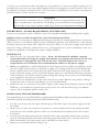
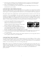
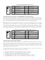
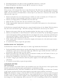
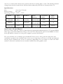
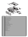
OVERTURE II
User’s Manual
At Antec, we continually refine and improve our products to ensure the highest quality. So it's
possible that your new case may differ slightly from the descriptions in this manual. This isn't
a problem; it's simply an improvement. As of the date of publication, all features, descriptions,
and illustrations in this manual are correct.
Disclaimer
This manual is intended only as a guide for Antec's Computer Enclosures. For
more comprehensive instructions on installing your motherboard and peripherals,
please refer to the user's manuals which come with your components and drives.
OVERTURE II – PIANO-BLACK MEDIA CENTER CASE
Your new case features a quiet ATX12V version 2.0 compliant SmartPower2 (SP2) power supply.
[Applies only to models designed for sale in the European Union:
SmartPower 2.0 series power supply models designed for the EU include Power Factor Correction
(PFC) circuitry in accordance with European standard regulation code EN61000-3-2. By altering
the input current wave shape, PFC improves the power factor of the power supply and results in
increased energy efficiency, reduced heat loss, prolonged life for power distribution and consumption equipment, and improved output voltage stability.]
SETTING UP
1. Place the case on a flat and stable surface. Note: the Overture II includes a special
version SmartPower 2.0 power supply that intakes cool air from the bottom of the case
and exhausts it through the side vent of the case. DO NOT place the case on a
carpeted floor or soft surface that could block the airflow to the power supply.
2. Note (not applicable to models designed for the European Union): Before installation, check
the red voltage switch setting on the power supply. The voltage switch is located behind the
power supply exhaust vent at the left side panel (with the front bezel facing you). It should
match your local voltage (115V for North America, Japan, etc. and 230V for Europe and many
other countries). If it doesn't match, please change the setting. If you don't you could damage
your equipment and void your warranty.
3. Remove the two thumbscrews at the rear from the top panel. Remove the panel by sliding it
towards the rear of the case and lifting it up. Set the panel aside.
4. Inside the case you should see the power supply, some wiring with marked connectors (USB,
PWR etc.), an installed I/O panel and a power cord. You will also find a bag of hardware
(screws, brass standoffs, plastic stands, etc.).
INSTALLING THE MOTHERBOARD
This manual does not cover CPU, RAM, or expansion card installation. Please consult your motherboard
manual for specific mounting instructions and troubleshooting.
1. Lay the case down, with the open side facing up. The drive cages and power supply should
be visible.
2. Make sure you have the correct I/O panel for your motherboard. If the panel provided
with the case isn't suitable, please contact your motherboard manufacturer for the correct
I/O panel.
3. Line up your motherboard with the standoff holes, and remember which holes are lined
up. Not all motherboards will match with all the provided holes; this is normal, and won't
affect functionally. (In other words, there will likely be extra holes.)
4. Remove your motherboard by lifting it up.
2
5. Screw the brass standoffs into the threaded holes that line up with your motherboard. Do
not overtighten the standoffs. Some standoffs may be pre-installed for your convenience.
6. Place your motherboard on the brass standoffs.
7. Screw in your motherboard to the standoffs with the provided Philips-head screws. Your
motherboard is now installed.
CONNECTING THE POWER AND LED
The power supply conforms to the latest ATX12V Version 2.0 standard. It is also backwards-compatible
with previous ATX form factor power supplies. Before you connect the power supply to any of your
devices, please consult the appropriate user manuals for your motherboard and other peripherals.
The power supply is also equipped with a 3-pin fan signal connector. Connect it to one of the fan
connectors on your motherboard. You may monitor the speed of the rear power supply fan
through your motherboard BIOS or through the monitoring software that's supplied with your
motherboard. Note: At low temperatures, the fan may run as slow as 950RPM. At these speeds,
some motherboards may not properly detect the fan speed and may generate false warnings of fan
failure. To ensure proper monitoring of the fan, please check your motherboard manual.
1. Connect the 24-pin Main Power Connector and the
Picture 2
Picture 1
4-pin +12V connector to your motherboard as
needed. If your motherboard uses a 20-pin
connector; detach the 4-pin attachment on the 24-pin
power connector (see pictures 1 and 2).
2. Connect the Reset switch (labeled RESET SW) to
your motherboard at the RST connector. The colored
For 24-pin
For 20-pin
motherboards
motherboards
wire should be attached to Pin 1 and the black wire to
ground. This applies for all the following connectors as well.
3. Connect the Power Switch (labeled POWER SW) to the PWR connector on your motherboard.
4. Connect the hard drive activity indicator (HDD LED) to the HDD LED header on
your motherboard.
5. To connect the audio speaker, find the mini speaker included in your tool bag and connect it
to the "speaker" header on your motherboard.
CONNECTING THE USB PORTS
You will find a single 10-pin connector on a cable attached to the front USB ports. This is an Intel
standard connector, which is keyed so that it can't be accidentally, reversed as long as it is connected
to a proper Intel standard motherboard header. Connect the 10-pin connector to your motherboard
headers so that the blocked pin fits over the missing header pin.
Note: Please check your motherboard manual for your USB header pin layout and make sure it
matches the attached table. If it does not match this Intel standard, please call Antec customer
support at (800) 22ANTEC (North America) or at +31 (0) 10 462-2060 (Europe) to buy a USB
adapter. This adapter will allow you to connect the front USB to your motherboard on a
pin-by-pin basis.
3
1
9
2
Intel Standard USB Header Pin Layout
Signal Names
Pin
Pin
Signal Names
1
USB Power 1
2
USB Power 2
3
Negative Signal 1
4
Negative Signal 2
5
Positive Signal 1
6
Positive Signal 2
7
Ground 1
8
Ground 2
9
Key (No Pin)
10
Empty Pin
10
CONNECTING THE IEEE 1394 (FIREWIRE®, I.LINK®) PORT
You will find a single 10-pin connector on a cable attached to the front IEEE 1394 connection.
This is an Intel standard connector, which is keyed so that it can't be accidentally reversed as long
as it is connected to a proper Intel standard motherboard header. Connect the 10-pin connector
to your motherboard header so that the blocked pin fits over the missing header pin.
Note: Please check your motherboard manual for your IEEE 1394 header pin layout and make
sure it matches the attached table. If you intend to connect the front FireWire port to an IEEE
1394 add-on card that comes with an external-type IEEE1394 connector, please call Antec customer
service at (800) 22ANTEC (North America) or +31 (0) 10 462-2060 (Europe) to purchase adapter.
This adapter will allow you to connect the front IEEE 1394 port to the external-type connector.
1
9
2
Standard Pin Assignment for IEEE 1394 Connector
Pin
Signal Names
Pin
Signal Names
1
TPA+
2
TPA–
3
Ground
4
Ground
5
TPB+
6
TPB–
7
+12V (Fused)
8
+12V (Fused)
9
Key (No Pin)
10
Ground
10
CONNECTING THE AUDIO PORTS
There is an Intel standard 10-pin connector (with 7 individual wires with connectors) coming out
from the front panel speaker and microphone connection. If your motherboard supports Intel's
standard onboard audio connector, you can plug in the 10-pin connector directly onto the board.
For non-Intel standard audio connection, you need to plug the 7 individual connectors to the
motherboard. See instruction below:
Locate the internal audio connectors from your motherboard or sound card. Consult your
motherboard or sound card manual for the pin-out positions.
1.
2.
3.
4.
5.
Microphone Signal Pin: Connect the MIC connector to this pin.
Microphone Power: Connect the MIC-BIAS connector to this pin.
Ground Pin: Connect the AUD GND connector to this pin.
Front Right Speaker Out Pin: Connect the FPOUT-R connector to this pin.
Front Right Speaker Out Pin: Connect the FPOUT-L connector to this pin.
4
6. Rear Right Speaker Out Pin: Connect the RET-R connector to this pin.
7. Rear Left Speaker Out Pin: Connect RET-L connector to this pin.
INSTALLING 3.5" DEVICES
There are two 3.5" external drive bays on the front bezel. The drive bays are right above the power
supply, and are fastened by two screws. These drive bays also come with hard drive mounting
holes. You can mount your hard drives to these bays if you choose to. Remove the screws and
slide the drive cage out.
1. Remove the drive bay cover from the bay in which you want to install your 3.5" device. To
remove the drive cover assembly, you'll have to remove two screws.
2. Mount your floppy drive or hard drive into the drive bay.
3. Slide the drive tray back into the case and lock it into position.
4. Find an appropriate 4-pin power connector on the power and connect it to the male 4-pin
on the device.
You'll find two internal hard drive bays in a cage located in front of the 92mm TriCool exhaust
fan, above the two-blower cage. The drive bay cage is fastened to the case by two screws.
1. Remove the screws, slide the cage forward and place the drive cage on a flat surface.
2. Mount your hard drive or other internal 3.5" device into the drive tray by threading the special
screws through the rubber grommets. Don't over-tighten the screws, since that could decrease
the grommets' ability to reduce vibration and noise. We suggest mounting the drives so that
the connectors face the front of the case.
3. Find a 4-pin molex connector on the power supply and connect it to the male 4-pin connec
tor on the device.
4. To install more drives, repeat the procedure.
INSTALLING 5.25" DEVICES
You'll find two external 5.25" drive bays in a drive cage behind the front bezel.
1. Push and hold the release button on the quick release lever and slide the lever to the right side
(clockwise) of the case to release the drive cage. Slide the cage towards the back of the case
and remove. Place the cage on a flat surface.
2. Remove the drive bay cover from the bay you intend to install your 5.25" device. To do so you
must unscrew the drive cover from the cage.
3. Install your CD-ROM or other device to the drive bay with the screws provided.
4. Connect a large 4-pin connector from the power supply to the male 4-pin connector on
the device.
5. To install a second drive, repeat the procedure.
COOLING SYSTEM
The TriCool fan
The case includes one 120mm TriCool fan installed in the rear. This fan has a three-speed switch
that lets you choose between quiet, performance, or maximum cooling.
(See specifications below.) The fan is installed so that the air is blowing out of the case. Connect
a large 4-pin connector from the power supply to the male 4-pin connector on the fan.
Note: The minimum voltage to start the fan is 5V. We recommend our users to set the fan speed
to High if you choose to connect the fan to a fan control device or to the Fan-Only connector
found on some of Antec's power supplies. A fan controlled device regulates the fan speed by varying
the voltage to it. The voltage may start as low as 4.5 V to 5V. Connecting a TriCool set on Medium
5
or Low to a fan-control device may result in the fan not being able to start. The already lowered
voltage from the fan control device will be further reduced by the TriCool circuitry below 5V.
Specifications:
Size:
92 x 92 x 25.4 mm
Rated Voltage:
DC 12V
Operating Voltage: 10.2V ~ 13.8V
Speed
Input
Current
Air Flow
Static
Pressure
Acoustical
Noise
Input
Power
High
2200 RPM
0.24A
(Max.)
1.08 m³/min.
(38 CFM)
1.04 mm-H2O
(0.08 inch-H2O)
27 dBA
1.4 W
Medium
1600 RPM
0.1A
1.09m³/min.
(28 CFM)
0.49 mm-H2O
(0.02 inch-H2O)
21 dBA
1.2 W
Low
1200 RPM
0.08A
0.60 m³/min.
(21 CFM)
0.27 mm-H2O
(0.01 inch-H2O)
14.6 dBA
0.96 W
The 75 mm x 30 mm Blowers
This case comes with two 75mm x 30mm blowers preinstalled underneath the 3.5" internal HDD
drive cage to provide additional cooling to the case. The blowers fan speed is 1600 RPM. Connect
the 4-pin Molex connector to the power supply to power the blowers.
The case includes two ventilated, pre-installed PCI slot covers. Along with the dual fans and
ventilated top panel, the ventilated slot covers act to help keep your case cool. We recommend
moving these ventilated slot covers if necessary (depending on your choice of PCI and AGP
cards) so that both ventilated covers remain installed near the graphics card.
6
1
2a
2b
19
18
3
5
4
17
6
16
15
7
9
14
13
8
12
11
10
Overture II - Explorer Description
No
Descriptions
1
Top Panel with Ventilation
2a
Normal Expansion Slot Cover
2b
Ventilated PCI Slot Covers
3
Internal 3.5" Drive Cage
4
Power Connector
5
92mm TriCool Fan
6
Universal I/O Panel
7
7530mm Blower Fan Mount Cage
8
7530mm Blower Fan Set
9
External 5.25" Drive Cage
10
Front Bezel
11
5.25" Drive Bay Cover
12
Power Button
13
Reset Button
14
3.5" Drive Bay Cover
15
Front Ports PCB Assembly
16
Power Supply
17
Power Supply Removable Vent
18
External 3.5" Drive Cage
19
Overture II Chassis
7
Antec, Inc.
47900 Fremont Blvd.
Fremont, CA 94538
Tel: 510-770-1200
Fax: 510-770-1288
Antec Europe B.V.
Sydneystraat 33
3047 BP Rotterdam
The Netherlands
Tel: +31 (0) 10 462-2060
Fax: +31 (0) 10 437-1752
Technical Support
US & Canada
1-800-22ANTEC
[email protected]
Europe
+31 (0) 10 462-2060
[email protected]
www.antec.com
© Copyright 2005 Antec, Inc. All rights reserved. All trademarks are the property of their respective owners.
Reproduction in whole or in part without written permission is prohibited. Printed in China.
Version 1.0.1 3/04/2005