1
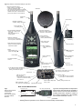
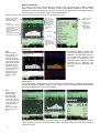
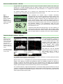
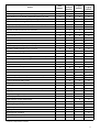
PRODUCT DATA Hand-held Analyzer Types 2250 and 2270 with Sound Level Meter Software BZ-7222, Frequency Analysis Software BZ-7223, Logging Software BZ-7224, Enhanced Logging Software BZ-7225, Signal Recording Option BZ-7226 and Tone Assessment Option BZ-7231 Type 2250 and Type 2270 are the innovative, 4th generation hand-held analyzers from Brüel & Kjær. The analyzers’ easy, safe and clever design philosophy is based on extensive research. Type 2250 has been awarded several prizes for its combination of excellent ergonomics and attractive design. Both analyzers can host a number of applications, including frequency analysis, logging (profiling) and signal recording, but in addition, Type 2270 adds dual-channel capabilities such as sound intensity/sound power measurements and dual-channel building acoustics applications. Applilcations are available separately at any time – or you can order a fully pre-configured instrument from the factory. The combination of application modules and innovative hardware makes these instruments into dedicated solutions for performing high-precision measurement tasks in environmental, occupational and industrial application areas. As a result, Brüel & Kjær delivers the functionality you need now, plus the capability to add more functionality later – this is a very secure investment. 120279 Uses and Features Uses Features • • • • • • • • • • • • • • • • • • • • • * Environmental noise assessment Occupational noise evaluation Reverberation Time measurements* Selection of hearing protection Noise reduction Product quality control Class 1 sound measurements to the latest international standards Real-time analysis of sound in 1/1- and 1/3-octave bands Tone assessment using 1/3-octave methods Loudness and noise rating measurements Analysis of time histories for broadband parameters and spectra (Logging) Documentation of measurements using text, voice and metadata annotations Documentation of measurements through recording of measured signals Logging up to 10 broadband parametersand 3 spectral parameters For more information, please refer to the relevant product data sheet. • • • • • • • • † Dual-channel measurement capabillity† Large, high-resolution, touch-sensitive color screen Data storage on high-capacity plug-in memory cards Communication via USB, LAN, or GPRS/3G modems Dynamic range in excess of 120 dB 3 Hz – 20 kHz broadband linear frequency range Recording measured signal during all or parts of a measurement (optional) Personalized measurement, display and job setup Integral digital camera for documentation and reference† “Smiley” quality indicators with hints and warnings Timers for automatic start of measurement PC software included for archiving, previewing and exporting data; software maintenance and remote online display Automatic detection of and correction for windscreen Weather data and GPS input Robust and environmentally protected (IP44) Type 2270 only. Applications and Hardware Introduction Types 2250 and 2270 have generous hardware and software specifications. They deliver an extremely flexible instrument that can cover your current and future measurement and analysis needs – from the traditional uses in assessing environmental and workplace noise to industrial quality control and development. These analyzers offer a technological platform for performing measurement applications in a compact and robust hand-held instrument. This data sheet describes different combinations of software modules (applications) available for Type 2250 and Type 2270. All instruments come with the Sound Level Meter Software BZ-7222 enabled. This makes them modern Class 1 Sound Level Meters (SLMs) and fulfill the requirements of the latest standard, IEC 61672–1, as well as earlier standards (see the specifications section for detailed compliance information). Even in their most basic configuration, these analyzers are delivered with a number of predefined measurement and display setups tailored to suit specific requirements. Optional Applications Additional applications that can be used in any combination can be purchased when needed and are delivered as easily installed licenses. Your hand-held analyzer investment is securely protected because when your need for measurements and analyses expands, these analyzers can accommodate your needs. Brüel & Kjær is committed to maintaining an ever-growing range of applications on these platforms. The optional applications described in this data sheet are: • Frequency Analysis Software BZ-7223 – analyse in real-time the 1/1- and 1/3-octave filter bands over a wide frequency range with a dynamic range from the noise floor in each individual band to 140 dB • Logging Software BZ-7224 – freely select parameters to log at periods from 1 s to 24 h. Running together with SLM Software, all broadband parameters can be logged. If Frequency Analysis Software is also enabled, spectra can be logged at the same rates. Logging (or noise profiling) is used to develop time histories for use in environmental noise as well as workplace noise assessment • Enhanced Logging Software BZ-7225 – continuously monitor and log periodic reports in addition to the features of Logging Software. Parameters such as Ldn and Lden are calculated • Signal Recording Option BZ-7226 – attach actual samples of the measured signal to your measurements. This option works with all other applications. The recording uses the measurement transducer, while voice annotations (standard) use a separate commentary microphone • Tone Assessment Option BZ-7231 – identify any 1/3-octave bands with audible tones above a set limit Information regarding the following applications can be found in their respective Product Data sheets: • Reverberation Time Software BZ-7227 – start a basic measurement by clapping your hands. The ‘traffic light’ shows measurement status at a glance, and the resulting reververation time (RT) spectrum is shown as well as the average RT for the room. For assessing the acoustic quality of auditoria, halls, public spaces and workplaces. (Product Data BP 2152) • Building Acoustics Software BZ-7228 and Dual-channel Building Acoustics Software BZ-7229 – assess sound insulation in buildings and of building elements. Airborne as well as impact sound insulation can be measured, and final results shown on the spot to international (ISO) and 12 national standards. The required sound sources and PC reporting software are available, as well as complete building acoustics systems. (Product Data BP 2190) • FFT Analysis Software BZ-7230 – analyse frequency using the Fast Fourier Transform (FFT) algorithm, the tool of choice for measurement and diagnostics of machinery noise and vibration. The frequency ‘profile’ of a machine is its fingerprint, revealing sources of noise and vibration and their paths to the measurement position. Useful in product development, troubleshooting, quality control and environmental noise measurements. With Tone Assessment Option BZ-7231, FFT Analysis offers objective indication of tonal noise audibility and annoyance (Product Data BP 2183) • Sound Intensity Software BZ-7233 (Type 2270 only) – make sound intensity measurements from beginning to end. A single user can make complete intensity measurements for total sound power and noise source location. You can use the built-in camera to take a photo to aid in probe placement during measurment and for use as a background for a map of the results (Product Data BP 2341) Long-term and Continuous Noise Monitoring For long-term and continuous noise monitoring, Brüel & Kjær offers a wide range of Noise Monitoring Terminal (NMT) and Noise Sentinel solutions that will meet and evolve with your needs. For more information, please consult Product Data BP 2379 for NMT solutions and Product Data BP 2389 for Noise Sentinel solutions. 2 Post-processing Software Measurement Partner Suite BZ-5503 is the next step in evolution from Utility Software BZ-5503, and its standard configuration is included with your hand-held analyzer. This configuration provides data archive, preview and export capabilities as well as software maintenance and remote online display. In addition to the free, standard configuration mentioned above, valuable data analysis and post-processing functionalities are now available in a growing suite of optional applications. Measurement Partner Suite offers these applications on a subscription basis: Only pay for what you need, when you need it. For more information on Measurement Partner Suite BZ-5503, please consult Product Data BP 2430. Additional post-processing applications (available separately) include: • Noise Explorer™ Type 7815 for data viewing and archiving • Evaluator™ Type 7820 for advanced environmental noise assessment • Protector™ Type 7825 for workplace noise assessment • Qualifier™ Type 7830 for building acoustic measurement analysis Connectivity Fig. 1 Secure access to measurement data from anywhere DDNS Service Provider Office Network Firewall Internet GPRS/3G Network GPRS/3G Modem/Router Smart Phone 120262 Remote Internet Communication Broadband Internet communication with Type 2250 and Type 2270 allows operation through routers, mobile broadband and firewalls with all the usual security protocols. These analyzers, with their support of IP EDGE or GPRS technologies for remote logging and instrument control, offers speed, price and coverage benefits over the now aging GSM technology. Alerting the Operator Email or SMS/text messages can be sent to a PC or mobile device to inform operators instantly of noise events that require a response, battery power levels that require attention, memory storage status, calibration status and many other user-programmed trigger conditions. This is a very low-cost solution for receiving important alerts. Secure Digital High Capacity (SDHC) SDHC memory cards complying with the new SD 2.0 standard, offer up to 32 GB of removable data storage. This enables very long signal recordings and measurement profiles to be made. 3 Using the Platform Great care has been taken to ensure that the hardware is ergonomically optimal in field use. Similarly, the software design has focused not only on making valid measurements but also on making field use efficient, convenient and intuitive. All user choices for setups (what to measure) and preferences (how to display it) are controlled using easy to understand lists, that can be expanded and collapsed. No more cluttered displays, choose only the parameters you want to see. Fig. 2 Key features of Hand-held Analyzer Type 2250 Microphone/Preamplifier Stage: • Falcon™ Range ½ microphone and microphone preamplifier stage • The microphone preamplifier stage is able to drive an extension cable of up to 100 m, a valuable feature when a measurement requires remote location of the microphone Windscreen Windscreen Sensor Navigation Pushbuttons: • Up/down, left/right arrow keys Event Pushbutton: • For marking events Stylus (stored) Back Erase/Exclude Pushbutton: • Allows you to erase the last 5 s of data • Mark logged data with an exclude marker Microphone for commentary Commentary Pushbutton: • Allows you to attach recorded messages to measurements Mounting thread Accept Pushbutton: • Accepts any changes made to parameters/setups Start/Pause Pushbutton: • Press to start a measurement • Press to pause a measurement Red, yellow, green Status Indicators Reset Measurement Pushbutton: • Allows you to reset Type 2250’s measurement buffers Non-slip surfaces for safe grip Store Pushbutton: • Store measurement results Display: • Touch sensitive color screen with backlight Battery Compartment for rechargeable battery pack Power Switch Cover for protecting connectors Thread for tripod/wrist strap G4 indicates hardware version 4 Output: • Output socket for softwaredetermined signals Trigger/Tacho Input 3.5 mm Stereo Socket for Headphones: • For reviewing recorded comments or listening to measurement signals Input: • For AC/DC or CCLD signals. Can be used when analysing electrical signals, for example, sound recordings Reset button USB 2.0 (On-the-Go) Micro-AB socket: • Allows data transfer and remote control of the instrument directly with a host PC Battery Charge: • 8 – 24 V DC input from a universal mains adapter or external batteries Battery Charge Indicator LED USB 2.0 Standard A socket • For connection to USB peripherals 4 High-speed LAN Interface Slots for Secure Digital (SD) memory cards 120011 Fig. 3 Key features of Hand-held Analyzer Type 2270 Microphone/Preamplifier Stage: • Falcon™ Range ½ microphone and microphone preamplifier stage • The microphone preamplifier stage is able to drive an extension cable of up to 100 m, a valuable feature when a measurement requires remote location of the microphone Windscreen Windscreen Sensor Stylus (stored) Navigation Pushbuttons: • Up/down, left/right arrow keys Camera Event Pushbutton: • For marking events Back Erase/Exclude Pushbutton: • Allows you to erase the last 5 s of data • Mark logged data with an exclude marker Commentary Pushbutton: • Allows you to attach recorded messages to measurements Accept Pushbutton: • Accepts any changes made to parameters/setups Start/Pause Pushbutton: • Press to start a measurement • Press to pause a measurement Microphone for commentary Red, yellow, green Status Indicators Reset Measurement Pushbutton: • Allows you to reset Type 2270’s measurement buffers Mounting thread Store Pushbutton: • Store measurement results Display: • Touch sensitive color screen with backlight Non-slip surfaces for safe grip Power Switch Cover for protecting connectors Battery Compartment for rechargeable battery pack G4 indicates hardware version 4 Output: • Output socket for softwaredetermined signals Thread for tripod/wrist strap Trigger/Tacho Input 3.5 mm Stereo Socket for Headphones: • For reviewing recorded comments or listening to measurement signals Input Channels 1 and 2: • For AC/DC or CCLD signals. Can be used when analysing electrical signals Reset button USB 2.0 (On-the-Go) Micro-AB socket: • Allows data transfer and remote control of the instrument directly with a host PC USB 2.0 Standard A socket • For connection to USB peripherals Battery Charge: • 8 – 24 V DC input from a universal mains adapter or external batteries 120261 Slots for Secure Digital (SD) memory cards Battery Charge Indicator LED High-speed LAN Interface Dual-channel Measurement Fig. 4 Setup for dual-channel measurements as used with Dual-channel Building Acoustics Software BZ-7229 Preamp ZC-0032 Type 2270 (with BZ-7229) Cable AO-0679 Dual 10-pole Adaptor Preamp ZC-0032 JP-1041 Microphone 4189 Microphone 4189 Cable AO-0679 Type 2270 is designed with two independent measurement channels with the potential to measure all the usual acoustic parameters, including third-octave frequency content at two locations simultaneously. This capability has a number of benefits, such as: 070135/1 • Reducing measurement time in multi-point tasks in building acoustics • Allowing real-time operations on two channels in sound intensity measurements 5 Display Capabilities As a user, you have several ways of tailoring the display to suit your specific needs. However, standard display elements are used to ensure uniformity, not only across different applications, but also across different users, setups and preferences. Once you have set up your measurement and display parameters the way you wish, you can save the setup in user-defined templates. Fig. 5 Typical display when (Left) measuring and (Right) modifying/updating the measurement setup. Status field: • Path and name of current project • Immediate textual feedback when pressing buttons • Information on measurement status Selected project template (including display and measurement setup) View area: • Contains all the parameters and results in numerical or graphical format • More than one view can be used for displaying the information • Select view using the View Tabs at bottom of view area Close and return to measurement Parameter values: • Changed via drop-downs • Active element is highlighted View area View tabs Shortcut bar: • Main menu button, brightness adjust, help, battery level, clock Appearance The analyzer applies a default color scheme for the display, as seen in most examples in this data sheet. However, you can adjust color schemes to suit your needs – for example, for very bright light (where maximum contrast is needed) or for night-time use (where no interference with night-vision is wanted). Fig. 6 Alternative display colour schemes – the left-hand display shows the maximumcontrast bright sunlight display. The right-hand display shows the night time display, which is optimised to take into account the physiology of human vision, allowing you to read the display without ruining your night vision. Data Display The analyzers make a distinction between the measurement made and how it is displayed. The anazlyzers measure all quantities in parallel; however, you can choose to view any measured quantity during or after measurement without affecting your measured data. Fig. 7 Logging Software BZ-7224 displays (from left to right): Profile with online sound marker, spoken commentary and note; current spectrum; and current broadband values. Select freely between these displays at any time For example, if logging broadband values and spectra, you can observe the profile, time history, overall or current spectrum, or overall or current broadband values. The display choice has no influence on what is measured or stored. 6 Sound Level Meter Software – BZ-7222 All Type 2250s and Type 2270s come with the Sound Level Meter Software enabled. This makes your analyzer into a versatile broadband SLM; the software complies with the latest international standard (IEC 61672–1) as well as previous international and national standards. For a complete list of measured parameters, see Specifications. The standard package allows you to document your measurements with written notes and voice annotations. Notes are added using a virtual keyboard on the touch screen. Fig. 8 Example of a typical SLM display, including the icons for added annotations, visible in the upper right corner Voice annotations are recorded using a separate commentary microphone when the commentary pushbutton is pushed and held. Voice annotations and notes can be attached before, during and after the measurement. Spoken comments during the measurement should, of course, be made during a pause or with the microphone placed at a distance using an extension cable. These unique features allows you to document your measurement (where, when, how, etc.) and always have this information attached to the measurement. Notes and voice annotations can be reviewed on the instrument itself or after the data has been transferred to a PC. If Signal Recording Option BZ-7226 (see page 10) is also enabled, you can record all or part of the measured signal. This recording is safely stored with the measurement. Thus it is easy to document that measured levels are indeed related to a particular noise source under investigation. Frequency Analysis Software – BZ-7223 Fig. 9 Frequency Analysis Software BZ-7223 displays (left to right): 1/3-octave showing dual spectra and generator icon, Cursor readouts, Loudness and Noise Rating (NR) results Frequency Analysis Software BZ-7223 is an optional application. It allows you to make real-time measurements in 1/1- and 1/3-octave bands over a wide frequency range. This makes it a simple matter to obtain spectra in order to, for example, select hearing protection, qualify heat and ventilation systems, and assess tonality. The decisive band and the corresponding NR curve is shown Each band has a full and unrivalled dynamic range from the noise floor in that particular band to 140 dB: a dynamic range generally in excess of 135 dB. The available frequency ranges are centre frequencies 8 Hz to 16 kHz (for 1/1-octave spectra) and centre frequencies 6.3 Hz to 20 kHz (1/3-octave spectra). Spectra can be A-, B-, C- or Z-weighted. Five spectra and full spectral statistics are measured and stored. In addition, seven different LN spectra and instantaneous values are available for display. Two spectra (for example, a minimum and maximum spectrum) can be superimposed on the display. All the broadband quantities measured by Sound Level Meter Software BZ-7222 are computed in parallel with the frequency analysis. Spectral analyses can be documented using notes and voice annotations. For a measured spectrum, single-number parameters, such as Noise Rating, Speech Interference Level and Loudness, can be calculated and displayed for noise impact analysis and limit comparison. A programmable generator is available for measurements requiring a sound source. You can select white or pink noise and set the upper and lower frequency limits. 7 Tone Assessment – BZ-7231 Fig. 10 Tone Assessment BZ-7231 showing 1/3-octave bands with audible tones over a set limit (identified by the blue dots) Tone Assessment (optional application) identifies any 1/3-octave bands with audible tones above a set limit. The assessment is based on the band’s prominence versus adjacent bands. The adjustment is the penalty to add to LAeq. Annoying tones in the spectrum may be assessed according to the ISO 1996 standard. The level of each 1/3-octave band is compared to the level of its neighbours, and all tones as well as the overall penalty (adjustment) are indicated. The search parameters are user adjustable to suit national requirements. NOTE: With the Tone Assessment option, the FFT Analysis application offers objective indication of tonal noise audibility and annoyance. For details, please refer to Product Data BP 2183. Logging Software – BZ-7224 With the optional Logging Software enabled, your analyzer becomes a versatile instrument for obtaining time histories. Logging Software allows you to select freely among the broadband parameters and log them at intervals from 1 s to 24 h. At the same time LAeq and/or LAF can be logged at 100 ms intervals. Fig. 11 Display showing part of profile with 100 ms resolution If Frequency Analysis Software BZ-7223 is enabled, the Logging Software additionally lets you log spectra at the same 1 s to 24 h intervals. Logging Software BZ-7224 incorporates a number of features designed to make difficult field work as manageable as possible. Some of these features are: • Five user-definable markers can be set on-the-fly in the profile. Use these, for example, to clearly indicate specific noise sources • Markers can be set directly on the profile display using the stylus and the touch screen. Simply ‘tap and drag’ on the part of the profile you want to mark and select a marker from the drop-down list • Markers can even be set after the fact. The display covers the latest 100 samples (100 s of profile when logging at 1 s intervals, otherwise more), so in most cases, you can wait for the event (or disturbance) to end before placing your marker. Alternatively, scroll back in the profile and set your marker • Browse easily between markers (like signal recordings) • The profile display can be ‘frozen’ at any time (this happens automatically when you tap the screen), allowing you to work at ease • Voice annotations, using the commentary microphone, are attached to the exact point on the profile where the annotation is made. With the microphone on an extension cable, comments can be associated with particular parts of the profile without interfering with the measurement All markers and annotations are saved with the measurement. No further bookkeeping is required. When importing data into Measurement Partner Suite BZ-5503 for further analyses, markers, as well as annotations, are directly accessible on the profile. Data are stored directly on SD cards. BZ-7224 includes a suitable SD card. Data can be directly read from the SD card by Measurement Partner. This means that even large amounts of data can be quickly transferred to a PC. Examples of the required memory follow (values should be compared to the standard size of the SD cards used, which start at 2 GB): • Five broadband parameters, no statistics: 1 Mbyte* • All broadband parameters, one 100 ms parameter: 7 Mbyte • All broadband parameters, one 100 ms parameter, all 1/3-octave spectra: 35 Mbyte • All broadband parameters, one 100 ms parameter, all 1/3-octave spectra, full statistics: 88 Mbyte * 8 These examples use values for 1 s logging periods for 24 h. Other values easily compute from these. Space needed for annotations and recordings must be added to this (10 s of voice annotation requires approximately 312 kB). Logging in the Field Fig. 12 Placing an All-weather Case on location Unattended measurements require protection against weather and unauthorised access, and the All-weather Case Type 3535-A fills the bill. Lightweight and robust, it will house a Type 2250-H Hand-held Analyzer and supply it with battery power for up to 90 hours of operation. A wide range of optional accessories are available to tailor the system capability to the logging task. Outdoor Microphone Type 4952 is shown in Fig. 12. When the system is left unattended, measurements and status can be monitored remotely with a wide range of options (see the Connectivity section). 120005 For details, please refer to Product Data BP 2251. Fig. 13 Automatic Charge Injection Calibration at beginning and end of a measurement Charge Injection Calibration (CIC) The Exclude marker shows that calibration is not part of the measurement With the Logging software, CIC can be set to run at the beginning and end of measurement. Fig. 14 Possible metadata entry types Metadata the Easy Way Shown are six userdefined metadata items and a selection menu for the Location item – this takes just four taps on the screen Measurement integrity is vital in any measurement application, particularly if the system is operating unattended. CIC provides a means of regularly auto-checking the measurement system for 10 s to ensure the continued and accurate operation of the system. With the Enhanced Logging Software BZ-7225, CIC can be programmed to run at up to four user-specified times in each 24 hour period. It may also be activated manually. Metadata are supplementary information about your measurement to help in archiving, retrieval and post-processing. Examples of metadata are the file name, date and time, setup and annotations made by the operator. The names and types of up to 10 text strings can be further defined. The type may be text you enter, text from a pick list you define, a number you enter or an index number that is automatically incremented or decremented when the measurement is saved. Metadata are available in all applications and may be used for sorting measurements in Measurement Partner Suite BZ-5503. Enhanced Logging Software – BZ-7225 Fig. 15 Display showing part of a report profile with 10 min resolution With the optional Enhanced Logging Software enabled, your analyzer is optimised for extended logging periods. It has the functionality of both Logging and Frequency Analysis software, but in addition it will: • • • • • Measure continuously, saving data to SD memory cards or USB devices Reboot automatically and resume operation in case of power failure Save data in manageable portions (every 24 hours), selectable for download Make periodic reports, i.e., log all measurement data at a preset report period Measure Ldn, Lden, Lday, Levening and Lnight 9 A periodic report is similar to the Measurement Total of the Logging software, except it is made periodically. It is useful for analysing sound levels over extended periods. If you combine periodic reports with leveltriggered event markers and Signal Recording Option BZ-7226, you have an overview as well as a focus on essential details. A typical setup for 24 hr of extended logging might be: • Continuous measurement • Hourly periodic reports • Level triggered marker for events above LAF = 60 dB(A) • Signal Recording of events (please refer to the Signal Recording Option BZ-7226) • Logging of other parameters as required (please refer to the Logging Software BZ-7224) After the measurement, you can check Ldn or Lden, the Total and the periodic reports, and then browse the events and sound recordings to verify the quality of your measurements. Signal Recording Option – BZ-7226 Signal Recording Option BZ-7226 works with all other applications. In all cases it allows you to make recordings of the actual measured signal, that is, the microphone signal used for acoustic measurements or the accelerometer used for vibration measurements (this must not be confused with recorded voice annotations, which use the commentary microphone). Recordings are automatically attached to the measurement and kept with it, even after transfer of the data to a PC. One purpose of the Signal Recording Option is to let you record the measurement signal in order to identify and document sound sources. Automatic gain control is available to allow for any signal level. For example: • The measured LAeq at 57 dB, did it actually stem from the rather distant compressor, or from other sources such as nearby birds or traffic? Not necessarily easy to evaluate on site, very difficult to document convincingly later. If the signal is recorded: No discussion • Is it really true that this noise is impulsive and should be penalised accordingly? If the signal is recorded: There may still be an argument, but it is then based on facts • Exceedances were identified while no operator was present. Did they originate from the plant under investigation or from another source. If the signal is recorded: No discussion Another important use of signal recording is to record the signal for later processing, such as analysing an engine run-up or a machinery process cycle. With Sound Level Meter Software BZ-7222 and Frequency Analysis Software BZ-7223, Signal Recording Option BZ-7226 lets you do the following: • Record all or parts of the measured signal giving rise to specific results, levels and spectra • Set up your instrument so that recording can be set to start automatically when the measurement is started, or you can initiate recordings manually With Logging Software BZ-7224 and Enhanced Logging Software BZ-7225, additional options are available: • Signal recording can be associated with the Event Marker. Use the Event key or set an event marker on the profile display: The sound during the event is recorded and attached to the appropriate part of the profile • Automatic detection of events based on level exceedance is also possible, meaning that recordings can also be initiated when no operator is present In all of the above cases the maximum duration of recordings can be set (the analyzer is only limited by available storage on the memory card currently in use). Recording signals may require large amounts of storage, therefore Signal Recording Option BZ-7226 allows you to decide on the trade-off between storage needed and recording quality (sampling rate). Overview of Software Features The table below presents a summary of the features of each of the application modules available with Type 2250 and Type 2270. See Specifications for details. 10 Feature Back-erase – last 5 seconds of measurement data 120+ dB Dynamic Range – no need for range switching Sound levels up to 140 dB with supplied Microphone Type 4189 Sound levels up to 152 dB using Microphone Type 4191 IEC/ANSI SLM standards Type/Class 1 Frequency weightings A, B, C, Z (linear) and time weightings F, S, I Free-field/diffuse-field correction Automatic windscreen detection and correction Preset time start/stop Multi-language user interface Context-sensitive help Voice, metadata and text annotation of measurements Display color-schemes optimised for day, night, indoor and outdoor use Personal login – protects your personal setups from other users Broadband statistics based on LAeq, LAF or LAS Broadband frequency range: 3 Hz – 20 kHz Remote control using GPRS/EDGE/3G modem Transfer of data files while measuring (USB, LAN or modem) Recording of measured signal during measurement Timers for automatic start of measurement Occupational health parameters Weather data and GPS input Tone assessment 1/1-octave spectra (centre frequencies 8 Hz to 16 kHz) 1/3-octave spectra (centre frequencies 6.3 Hz to 20 kHz) Spectral statistics based on LAF or LAS Loudness and Noise Rating results Charge Injection Calibration (CIC) Level triggers and recordings Logging of all or selected broadband parameters and spectra Logging period 1 s to 24 h LAeq, LAS, LAF logged every 100 ms Profile display Profile overview of entire measurement Markers on profile display Recording of signal during noise events Periodic reports of all measured data Report period 1 min to 24 h Timer trigger for recordings Ldn, Lden, Lday, Levening, Lnight Continuous measurement * † SLM Software * Frequency Analysis Software * Logging Software * † † † † * Enhanced Logging Software * † † † † * If Signal Recording Option is enabled If Frequency Analysis Software is enabled 11 Compliance with Standards CE-mark indicates compliance with the EMC Directive and Low Voltage Directive. C-Tick mark indicates compliance with the EMC requirements of Australia and New Zealand. Safety EN/IEC 61010–1, ANSI/UL 61010–1 and CSA C22.2 No.1010.1: Safety requirements for electrical equipment for measurement, control and laboratory use. EMC Emission EN/IEC 61000–6–3: Generic emission standard for residential, commercial and light industrial environments. CISPR 22: Radio disturbance characteristics of information technology equipment. Class B Limits. FCC Rules, Part 15: Complies with the limits for a Class B digital device. IEC 61672–1, IEC 61260, IEC 60651 and IEC 60804: Instrumentation standards. Complies with Canadian standard ICES–001 EMC Immunity EN/IEC 61000–6–2: Generic standard – Immunity for industrial environments. EN/IEC 61326: Electrical equipment for measurement, control and laboratory use – EMC requirements. IEC 61672–1, IEC 61260, IEC 60651 and IEC 60804: Instrumentation standards Hand-held Analyzer Type 2250/2270 Platform Specifications apply to Type 2250/2270 fitted with Microphone Type 4189 and Microphone Preamplifier ZC-0032 Microphone SUPPLIED MICROPHONE Type 4189: Prepolarized Free-field ½ Microphone or Type 4190: Free-field ½ Microphone Nominal Open-circuit Sensitivity: 50 mV/Pa (corresponding to 26 dB re 1 V/Pa) ± 1.5 dB Capacitance: 14 pF (at 250 Hz) MICROPHONE PREAMPLIFIER ZC-0032 Nominal Preamplifier Attenuation: 0.25 dB Connector: 10-pin LEMO Extension Cables: Up to 100 m in length between the microphone preamplifier and Type 2250/2270, without degradation of the specifications Accessory Detection: Windscreen UA-1650 can be automatically detected when fitted over ZC-0032 MICROPHONE POLARIZATION VOLTAGE Selectable between 0 V and 200 V SELF-GENERATED NOISE LEVEL Typical values at 23°C for nominal microphone open-circuit sensitivity: Weighting Microphone Electrical Total “A” 14.6 dB 12.4 dB 16.6 dB “B” 13.4 dB 11.5 dB 15.6 dB “C” 13.5 dB 12.9 dB 16.2 dB “Z” 5 Hz–20 kHz 15.3 dB 18.3 dB 20.1 dB “Z” 3 Hz–20 kHz 15.3 dB 25.5 dB 25.9 dB Interface KEYBOARD Pushbuttons: 11 keys with backlight, optimised for measurement control and screen navigation ON-OFF BUTTON Function: Press 1 s to turn on; press 1 s to enter standby; press for more than 5 s to switch off STATUS INDICATORS LEDs: Red, amber and green DISPLAY Type: Transflective back-lit colour touch screen 240 320 dot matrix 12 Colour Schemes: Five different – optimised for different usage scenarios (day, night, etc.) Backlight: Adjustable level and on-time USER INTERFACE Measurement Control: Using pushbuttons on keyboard Setup and Display of Results: Using stylus on touch screen or pushbuttons on keyboard Lock: Keyboard and touch screen can be locked and unlocked USB INTERFACE USB 2.0 OTG Micro AB and USB 2.0 Standard A sockets MODEM INTERFACE Connection to Internet through GPRS/EDGE/HSPA modem connected through: • the USB Standard A Socket Supports DynDNS for automatic update of IP address of host name PRINTER INTERFACE PCL printers, Mobile Pro Spectrum thermal printer or Seiko DPU S245/S445 thermal printers can be connected to USB socket MICROPHONE FOR COMMENTARY Microphone, which utilises Automatic Gain Control (AGC), is incorporated in underside of analyzer. Used to create voice annotations for attaching to measurements CAMERA (TYPE 2270 ONLY) Camera with fixed focus and automatic exposure is incorporated in underside of analyzer. Used to create image annotations for attaching to measurements Image Size: • 2048 1536 pixels Viewfinder Size: 212 160 pixels Format: jpg with exif information Inputs/Outputs SECURE DIGITAL SOCKET • 2 SD sockets Connect SD and SDHC memory cards LAN INTERFACE SOCKET • Connector: RJ45 Auto-MDIX • Speed: 100 Mbps • Protocol: TCP/IP INPUT SOCKET (2 – TYPE 2270 ONLY) Connector: Triaxial LEMO Input Impedance: 1 M Direct Input: Max. input voltage: ± 14.14 Vpeak CCLD Input: Max. input voltage: ± 7.07 Vpeak CCLD Current/voltage: 4 mA/25 V Storage TRIGGER SOCKET Connector: Triaxial LEMO Max. Input Voltage: ± 20 Vpeak Input Impedance: > 47 k Precision: ± 0.1 V USB MEMORY STICK For store/recall of measurement data OUTPUT SOCKET Connector: Triaxial LEMO Max. Peak Output Level: ± 4.46 V Output Impedance: 50 HEADPHONE SOCKET Connector: 3.5 mm Minijack stereo socket Max. Peak Output Level: ± 1.4 V Output Impedance: 32 in each channel Power EXTERNAL DC POWER SUPPLY REQUIREMENTS Used to charge the battery pack in the analyzer Voltage: 8 – 24 V DC, ripple voltage < 20 mV Current Requirement: min. 1.5 A Power Consumption: < 2.5 W, without battery charging, < 10 W when charging Cable Connector: LEMO Type FFA.00, positive at centre pin EXTERNAL AC MAIN SUPPLY ADAPTOR Part No.: ZG-0426 Supply Voltage: 100 – 120/200 – 240 VAC; 47 – 63 Hz Connector: 2-pin IEC 320 BATTERY PACK Part No.: QB-0061 Rechargeable Li-Ion battery Voltage: 3.7 V Capacity: 5200 mAh nominal Typical Operating Time: • Single-channel: >11 h (screen backlight dimmed); >8.5 h (full screen backlight) • Dual-channel: >7.5 h (full screen backlight) Use of external interfaces (LAN, USB, WLAN) will decrease battery operating time Battery Cycle Life: > 500 complete charge/discharge cycles Battery Aging: Approximately 20% loss in capacity per year Battery Indicator: Remaining battery capacity and expected working time may be read out in % and in time Battery Fuel Gauge: The battery is equipped with a built-in fuel gauge, which continuously measures and stores the actual battery capacity in the battery unit Charge Time: In analyzer, typically 10 hours from empty at ambient temperatures below 30C. To protect the battery, charging will be terminated completely at ambient temperatures above 40C. At 30 to 40C charging time will be prolonged. With External Charger ZG-0444 (optional accessory), typically 5 hours Note: It is not recommended to charge the battery at temperatures below 0C (32F) or over 50C (122F). Doing this will reduce battery lifetime CLOCK Back-up battery powered clock. Drift < 0.45 s per 24 hour period INTERNAL FLASH-RAM (NON-VOLATILE) For user setups and measurement data: 512 MB EXTERNAL SECURE DIGITAL MEMORY CARD SD and SDHC Card: For store/recall of measurement data Environmental WARM-UP TIME From Power Off: < 2 minutes From Standby: < 10 seconds for prepolarized microphones TEMPERATURE IEC 60068–2–1 & IEC 60068–2–2: Environmental Testing. Cold and Dry Heat. Operating Temperature: –10 to + 50C (14 to 122F), < 0.1 dB Storage Temperature: –25 to +70C (–13 to +158F) HUMIDITY IEC 60068–2–78: Damp Heat: 90% RH (non-condensing at 40C (104F)). Effect of Humidity: < 0.1 dB for 0% < RH < 90% (at 40°C (104°F) and 1 kHz) MECHANICAL Environmental Protection: IP44 Non-operating: IEC 60068–2–6: Vibration: 0.3 mm, 20 m/s2, 10 – 500 Hz IEC 60068–2–27: Shock: 1000 m/s2 IEC 60068–2–29: Bump: 4000 bumps at 400 m/s2 WEIGHT AND DIMENSIONS 650 g (23 oz.) including rechargeable battery 300 93 50 mm (11.8 3.7 1.9) including preamplifier and microphone User Interface USERS Multi-user concept with login. Users can have their own settings with jobs and projects totally independent of other users PREFERENCES Date, Time and Number formats can be specified per user LANGUAGE User Interface in Catalan, Chinese (People’s Republic of China), Chinese (Taiwan), Croatian, Czech, Danish, English, Flemish, French, German, Hungarian, Japanese, Italian, Korean, Polish, Portuguese, Romanian, Russian, Serbian, Slovenian, Spanish, Swedish and Turkish HELP Concise context-sensitive help in English, French, German, Italian, Japanese, Korean, Polish, Portuguese, Romanian, Serbian, Slovenian and Spanish UPDATE OF SOFTWARE Update to any version using BZ-5503 through USB or update via Internet: • any version from 4.0 and up WEB PAGE Connect to the analyzer using an Internet browser supporting JavaScript. The connection is password protected Two levels of protection: • Guest level: for viewing only • Administrator level: for viewing and full control of the analyzer 13 Software Specifications – Sound Level Meter Software BZ-7222 For Display and Storage Start Time Stop Time Overload % Elapsed Time LXeq LYeq LXE LYE LCeq-LAeqk LXSmax LXFmax LXImax LYSmax LYFmax LYImax LXSmin LXFmin LXImin LYSmin LYFmin LYImin LXIeq LYIeq LAIeq-LAeq LAFTeq LAFTeq-LAeq Time Remaining Lep,d Lep,dv E Input Dose Proj. Dose Lvpeak CHANNELS (Type 2270 only) All measurements are made from either Ch.1 or Ch.2 #VPeaks (>NNNdB) #VPeaks (>137dB) #VPeaks (>135dB) TVpeak LavUQ TWA TWAv DoseUQ Proj. DoseUQ Conforms with the following National and International Standards: • IEC 61672–1 (2002–05) Class 1 • IEC 60651 (1979) plus Amendment 1 (1993–02) and Amendment 2 (2000–10), Type 1 • IEC 60804 (2000–10 ), Type 1 • DIN 45657 (1997– 07) • ANSI S1.4 –1983 plus ANSI S1.4A–1985 Amendment, Type 1 • ANSI S1.43–1997, Type 1 Note: The International IEC Standards are adopted as European standards by CENELEC. When this happens, the letters IEC are replaced with EN and the number is retained. Type 2250/2270 also conforms to these EN Standards TRANSDUCERS Transducers are described in a transducer database with information on Serial Number, Nominal Sensitivity, Polarization Voltage, Free-field Type, CCLD required, Capacitance and additional information. The analogue hardware is set up automatically in accordance with the selected transducer CORRECTION FILTERS For Microphone Types 4189, 4190, 4191, 4193, 4950, 4952 and 4184-A, BZ-7222 is able to correct the frequency response to compensate for sound field and accessories: Sound Field: Free-field or diffuse-field (for Types 4952 and 4184-A only: 0 (Top) reference direction and 90° (Side) reference direction) Accessories: • Types 4189 and 4190 only: None, Windscreen UA-1650 or Outdoor Microphone Kit UA-1404 • Types 4191 and 4193 only: None or Windscreen UA-1650 • Type 4950 only: None or Windscreen UA-0237 For Accelerometer Types 4397-A, 4513, 4513-001, 4513-002, 4514, 4514-001, 4514-002, 8341, 8324 and 6233C-10 the lower frequency limit will be optimized to match the specifications for the accelerometer Analysis DETECTORS Parallel detectors on every measurement: A- or B-weighted (switchable): Broadband detector channel with three exponential time weightings (Fast, Slow, Impulse), one linearly averaging detector and one peak detector C- or Z-weighted (switchable): As for A- or B-weighted Overload Detector: Monitors the overload outputs of all the frequencyweighted channels MEASUREMENTS X = frequency weightings A or B Y = frequency weightings C or Z V = frequency weightings A, B, C or Z N = number between 0.1 and 99.9 Q = exchange rate 4, 5 or 6 dB U = time weightings F or S For Storage Full statistics 14 Weather Data (requires connection to a weather station): Wind Dir. avg. Wind Speed avg. Amb. Temperature Wind Dir. min. Wind Speed min. Amb. Humidity Wind Dir. max. Wind Speed max. Amb. Pressure Amb. Rain Gauge Only for Display as Numbers or Quasi-analog Bars: LXS LXF LXI LYS LYF LYI LXS(SPL) LXF(SPL) LXI(SPL) LYS(SPL) LYF(SPL) LYI(SPL) LXN1 or LXUN1 LXN2 or LXUN2 LXN3 or LXUN3 LXN4 or LXUN4 LXN5 or LXUN5 LXN6 or LXUN6 LXN7 or LXUN7 LVpeak,1s Trig. Input Voltage Std.Dev. Instantaneous Weather Data: Wind Dir. Wind Speed Instantaneous GPS Data: Latitude Longitude MEASURING RANGES When using Microphone Type 4189: Dynamic Range: From typical noise floor to max. level for a 1 kHz pure tone signal, A-weighted: 16.6 to 140 dB Primary Indicator Range: In accordance with IEC 60651, A-weighted: 23.5 dB to 122.3 dB Linearity Range: In accordance with IEC 60804, A-weighted: 21.4 dB to 140.8 dB Linear Operating Range: In accordance with IEC 61672, A-weighted: 1 kHz: 24.8 dB to 139.7 dB Peak C Range: In accordance with IEC 61672, 1 kHz: 42.3 dB to 142.7 dB SAMPLING FOR STATISTICS The Statistics can be based on either LXF, LXS or LXeq: • Statistics LXFN1-7 or LXSN1-7 are based on sampling LXF or LXS, resp., every 10 ms into 0.2 dB wide classes over 130 dB • Statistics LXN1-7 are based on sampling LXeq every second into 0.2 dB wide classes over 130 dB Full distribution saved with measurement The Std.Dev. (Standard Deviation) parameter is calculated from the statistics Measurement Display and Control Annotations MEASUREMENT DISPLAYS SLM: Measurement data displayed as numbers of various sizes and one quasi-analog bar Measured data are displayed as dB values, housekeeping data as numbers in relevant format. Instantaneous measurement LXF is displayed as a quasi-analog bar VOICE ANNOTATIONS Voice annotations can be attached to measurements so that verbal comments can be stored together with the measurement Playback: Playback of voice annotations can be listened to using an earphone/headphones connected to the headphone socket Gain Adjustment: –60 dB to 0 dB MEASUREMENT CONTROL Manual: Manually controlled single measurement Automatic: Pre-set measurement time from 1 s to 24 hr in 1 s steps Manual Controls: Reset, Start, Pause, Back-erase, Continue and Store the measurement manually Auto-start: A total of 10 timers allow set up of measurement start times up to a month in advance. Each timer can be repeated. Measurements are automatically stored when completed TEXT ANNOTATIONS Text annotations can be attached to measurements so that written comments can be stored with the measurement BACK-ERASE The last 5 s of data can be erased without resetting the measurement Measurement Status ON SCREEN Information such as overload and running/paused are displayed on screen as icons TRAFFIC LIGHTS Red, yellow and green LEDs show measurement status and instantaneous overload as follows: • Yellow LED flash every 5 s = stopped, ready to measure • Green LED flashing slowly = awaiting calibration signal • Green LED on constantly = measuring • Yellow LED flashing slowly = paused, measurement not stored • Red LED flashing quickly = intermittent overload, calibration failed NOTIFICATIONS Sends an SMS or e-mail if an alarm condition is fulfilled Alarm Conditions: • Disk Space below set value • Trig. Input Voltage below set value • Internal Battery enters set state • Change in Measurement State • Reboot of analyzer GPS ANNOTATIONS A text annotation with GPS information can be attached (Latitude, Longitude, Altitude and position error). Requires connection to a GPS receiver IMAGE ANNOTATIONS (TYPE 2270 ONLY) Image annotations can be attached to measurements. Images can be viewed on the screen. Calibration Initial calibration is stored for comparison with later calibrations ACOUSTIC Using Sound Calibrator Type 4231 or custom calibrator. The calibration process automatically detects the calibration level when Sound Calibrator Type 4231 is used ELECTRICAL Uses internally generated electrical signal combined with a typed-in value of microphone sensitivity CALIBRATION HISTORY Up to 20 of the last calibrations made are listed and can be viewed on the analyzer Data Management METADATA Up to 10 metadata annotations can be set per project (text from keyboard or text from pick list, number from keyboard or auto generated number) Signal Monitoring PROJECT TEMPLATE Defines the display and measurement setups. Setups can be locked and password protected The input signal can be monitored using an earphone/headphones connected to the headphone socket, or it can be fed to the output socket PROJECT Measurement data stored with the project template OUTPUT SIGNAL Input Conditioned: A-, B-, C- or Z-weighted Gain Adjustment: –60 dB to 60 dB LXF output (every ms) as a DC voltage between 0 V and 4 V DC output for calibration purposes: 0 dB ~ 0 V and 200 dB ~ 4 V JOB Projects are organised in jobs Explorer facilities for easy management of data (copy, cut, paste, delete, rename, view data, open project, create job, set default project name) HEADPHONE SIGNAL Input signal can be monitored using this socket with headphones/earphones Gain Adjustment: –60 dB to 60 dB 15 Software Specifications – Frequency Analysis Software BZ-7223 The specifications for BZ-7223 include the specifications for Sound Level Meter Software BZ-7222. BZ-7223 adds: Standards Conforms with the following National and International Standards: • IEC 61260 (1995–07) plus Amendment 1 (2001– 09), 1/1-octave Bands and 1/3-octave Bands, Class 0 • ANSI S1.11–1986, 1/1-octave Bands and 1/3-octave Bands, Order 3, Type 0–C • ANSI S1.11– 2004, 1/1-octave Bands and 1/3-octave Bands, Class 0 Input CHANNELS (TYPE 2270 ONLY) All measurements are made from either Ch.1 or Ch.2 Frequency Analysis CENTRE FREQUENCIES 1/1-oct. Band Centre Frequencies: 8 Hz to 16 kHz 1/3-oct. Band Centre Frequencies: 6.3 Hz to 20 kHz MEASUREMENTS X = frequency weightings A, B, C or Z , Y = time weightings F or S Data for Storage Full Spectral Statistics Spectra for Display and Storage LXeq LXSmax LXFmax LXSmin LXFmin Spectra for Display Only LXS LXF LXYN2 LXYN3 LXYN5 LXYN6 Single Values SIL LXeq(f1-f2)a NR RC NCB NC Loudness a PSIL LXYN1 LXYN4 LXYN7 SIL3 NR Decisive Band RC Classification NCB Classification NC Decisive Band Loudness Level where f1 and f2 are frequency bands in the spectrum. MEASURING RANGES When using Microphone Type 4189: Dynamic Range: From typical noise floor to max. level for a pure tone signal at 1 kHz 1/3-octave: 1.1 to 140 dB Linear Operating Range: In accordance with IEC 61260, 1/3-octave: 20.5 dB to 140 dB 16 SAMPLING FOR OCTAVE OR 1/3-OCTAVE STATISTICS X = frequency weightings A or B The Statistics can be based on either LXF or LXS: • Statistics LXFN1-7 or LXSN1-7 are based on sampling LXF or LXS, respectively, every T ms into 1 dB wide classes over 150 dB; T = 100 for frequency range set to 12.5 – 20 kHz T = 200 for frequency range set to 6.3 – 20 kHz Full distribution can be saved with measurement Displays MEASUREMENT DISPLAYS Spectrum: One or two spectra superimposed + A/B and C/Z broadband bars Table: One or two spectra in tabular form Y-axis: Range: 5, 10, 20, 40, 60, 80, 100, 120, 140 or 160 dB. Auto zoom or auto scale available Cursor: Readout of selected band Generator INTERNAL GENERATOR Built-in pseudo-random noise generator Spectrum: Selectable between Pink and White Crest Factor: Pink Noise: 4.4 (13 dB) White Noise: 3.6 (11 dB) Bandwidth: Selectable: • Lower Limit: 50 Hz (1/3-oct.) or 63 Hz (oct.) • Upper Limit: 10 kHz (1/3-oct.) or 8 kHz (oct.) Output Level: Independent of bandwidth • Max.: 1 Vrms (0 dB) • Gain Adjustment: –60 to 0 dB When bandwidth is changed, the level for all bands is automatically adjusted to comply with the set output level Correction Filters: For sound sources Type 4292, Type 4295 and Type 4296: Flat or Optimum Repetition Period: 175 s Output Connector: Output socket EXTERNAL GENERATOR Selectable as alternative to Internal Generator To control external noise generator, set: • Levels: 0 V (Generator off), 4.5 V (Generator on) • Rise-time and Fall-time: 10 s The noise generator is turned on and off automatically during the measurement Escape Time: 0 to 60 s Build-up Time: 1 to 10 s The generator can be turned on and off manually for checking equipment and sound levels Software Specifications – Logging Software BZ-7224 The specifications for BZ-7224 include the specifications for Sound Level Meter Software BZ-7222. BZ-7224 adds: Logging MEASUREMENTS Logging: Measurement data logged at pre-set periods into files on: • SD Card • USB Memory Stick Logging Period: From 1 s to 24 hr with 1 s resolution Fast Logging: LAF, LAS and LAeq can be logged every 100 ms, irrespective of logging period Broadband Data Stored at each Logging Interval: All, or up to 10 selectable broadband data incl. Trig. Input Voltage, and Weather data Broadband Statistics Stored at each Logging Interval: Full distribution, or none Spectrum Data Stored at each Logging Interval: All, or up to three selectable spectra (license for BZ-7223 required) Spectral Statistics Stored at each Logging Interval: Full distribution, or none (license for BZ-7223 required) Logging Time: From 1 s to 31 days using Preset Logging Time with 1 s resolution Measurement Total: For the logging time, in parallel with logging: All broadband data, statistics and spectra (license for BZ-7223 required) MARKERS One data exclusion marker and four user-definable markers for on-line marking of sound categories heard during the measurement Events can be set manually TRIGGERS Markers can be set and signal recordings can be started (license for BZ7226 required) when a broadband level is above or below a specified level ANNOTATIONS On-line annotations with spoken comments, written notes or images (Type 2270 only) Calibration CIC (CHARGE INJECTION CALIBRATION) Injects an internally generated electrical signal in parallel with the microphone diaphragm. A manual CIC can be performed whenever there is no measurement in progress An automatic CIC can be performed at the start and end of a logging measurement Measurement Displays Profile: Graphical display of selectable measurement data versus time. Fast display of next or previous marker, profile overview of entire measurement Y-axis: Range: 5, 10, 20, 40, 60, 80, 100, 120, 140 or 160 dB. Auto zoom or auto scale available X-axis: Scroll facilities Cursor: Readout of measurement data at selected time Notifications Alarm Conditions (in addition to those specified for BZ-7222): • CIC failed • Trigger Level exceeded Software Specifications – Enhanced Logging Software BZ-7225 The specifications for BZ-7225 include the specifications for Logging Software BZ-7224. BZ-7225 adds: Logging For Display and Storage Ldn, Lden, Lday, Levening and Lnight Selectable Day, Evening and Night periods and penalties Periodic Reports: Measurement data logged at a pre-set report period into files on: • SD Card • USB Memory Stick Report Period: From 1 min to 24 hr with 1 min resolution Broadband Data and Statistics Stored at each Reporting Interval: All including Weather data Spectrum Data Stored at each Reporting Interval: All (license for BZ-7223 required) Spectral Statistics Stored at each Reporting Interval: Full distribution, or none (license for BZ-7223 required) Logging Time: From 1 s to 31 days with using Preset Logging with 1 s resolution or Continuous Data are saved in separate projects for every 24 hrs of logging – at a user-defined time of day Automatic reboot and resume of operation in case of power failure TRIGGERS Timer Trigger For periodically starting a signal recording (license for BZ-7226 required) Level Triggers Markers can be set and signal recordings can be started (license for BZ-7226 required) when a broadband or frequency band level is above or below a specified level. Hold off time between triggers can be set. You can specify up to four independent Level Triggers to be active at four different times during the day Calibration CHARGE INJECTION CALIBRATION (CIC) Injects an internally generated electrical signal in parallel with the microphone diaphragm. A manual CIC can be performed whenever there is no measurement in progress An automatic CIC can be performed at the start and end of a logging measurement. The CIC can be set to occur up to 4 times in each 24 hour period CIC Duration: 10 s 17 Software Specifications – Signal Recording Option BZ-7226 Signal Recording Option BZ-7226 is enabled with a separate license. It works with all the software for Type 2250/2270: Sound Level Meter, Frequency Analysis, Logging Software, Enhanced Logging Software and Reverberation Time Software For data storage, Signal Recording requires: • SD Card • USB Memory Stick RECORDING FORMAT The recording format is 16-bit wave files (extension .wav) attached to the data in the project, easily played-back afterwards on a PC using BZ-5503, Type 7820 or 7825. Calibration information is stored in the wav file, allowing PULSE to analyse the recordings RECORDED SIGNAL A-, B-, C- or Z-weighted signal from the measurement transducer Manual Control of Recording: Recording can be manually started and stopped during a measurement using a pushbutton or an external signal Automatic Control of Recording: Start of recording when measurement is started. Minimum and Maximum recording time can be preset AUTOMATIC GAIN CONTROL The average level of the signal is kept within a 40 dB range, or the gain can be fixed SAMPLING RATE AND PRE-RECORDING The signal is buffered for the pre-recording of the signal. This allows the beginning of events to be recorded even if they are only detected later. Sampling Rate (kHz) Maximum Pre-recording (s) Sound Quality Memory (KB/s) 8 470 Low 16 16 230 Fair 32 24 150 Medium 48 48 70 High 96 Functions with BZ-7222 and BZ-7223 Functions with BZ-7224 and BZ-7225 Manual Control of Recording (using Manual Event or Back-erase pushbutton, or an external signal): Recording during all of the event, or for preset minimum and maximum duration. A Sound marker is set while recording. Selectable pre- and post-recording time Manual Control of Recording (using touch screen): Recording for the selected time period (subject to the limitations of the pre-recording buffer). A Sound marker is set for the selected time period Automatic Control of Recording: An event can be triggered when a broadband level is above or below a specified level. Recording during all of the event or for preset minimum and maximum duration. Selectable pre- and post-recording time Functions with BZ-7227 PLAYBACK Playback of signal recordings can be listened to using the earphone/headphones connected to the headphone socket Automatic Control of Recording: Start of recording when measurement is started Software Specifications – Tone Assessment Option BZ-7231 LICENSE Tone Assessment Option BZ-7231 is enabled with a separate license and can be used with the FFT template (BZ-7230) or with 1/3-octave and logging template (BZ-7223, BZ-7224 and BZ-7225) 1/3-octave Based Tone Assessment (with BZ-7223/24/25 Only) Tone assessment is based on the measured 1/3-octave spectrum in accordance with either the international ‘ISO 1996:2007 Acoustics – Description, assessment and measurement of environmental noise – part 2: Determination of environmental noise levels. Annex D (informative) Objective method for assessing the audibility of tones in noise – Simplified method’ or the Italian law ‘DM 16-03-1998: Ministero dell'ambiente, Decreto 16 marzo 1998’ SPECTRA ASSESSED The displayed 1/3-octave spectrum (Leq, Lmax or Lmin) may be assessed. Assessment is made as post-processing, that is, when measurement is paused or stopped 18 SETUP ACCORDING TO STANDARD Setups in violation of the standard are indicated as such on the display. You can then accept to apply the default setup. Tone assessment will be made if possible, in spite of standard violations. For tone assessment according to ISO 1996-2, Annex D, you can set the division between the Low and Middle frequency range, the division between the Middle and High frequency range, and the limits for the level differences between adjacent bands. For tone assessment according to DM 16-03-1998, the tones are tested against loudness contours. Select between ISO 226: 1987 Free-field, 1987 Diffuse-field and 2003 Free-field RESULTS Tones are indicated above the spectrum when Tone is selected as spectrum parameter. The resulting adjustment can be viewed on the Value panel. It is not saved with the measurement QUALITY INDICATORS On the display, a quality indicator (smiley) will indicate that a hint is available for tone assessment quality. Click on the indicator to see the hint Software Specifications – Measurement Partner Suite BZ-5503 BZ-5503 is included with Type 2250/2270 for easy synchronisation of setups and data between PC and Type 2250/2270. BZ-5503 is supplied on DVD BZ-5298 ONLINE DISPLAY OF TYPE 2250/2270 DATA Measurements on Type 2250/2270 can be controlled from the PC and displayed online with the PC, using the same user interface on the PC as on Type 2250/2270 DATA MANAGEMENT Explorer: Facilities for easy management of analyzers, users, jobs, projects and project templates (copy, cut, paste, delete, rename, create) Data Viewer: View measurement data (content of projects) Synchronisation: Project Templates and Projects for a specific user can be synchronised between the PC and Type 2250/2270 USERS Users of Type 2250/2270 can be created or deleted EXPORT FACILITIES Excel: Projects (or user-specified parts) can be exported to Microsoft® Excel® Brüel & Kjær Software: Projects can be exported to Predictor-LimA Type 7810, Noise Explorer Type 7815, Acoustic Determinator Type 7816, Evaluator Type 7820, Protector Type 7825 or Qualifier (Light) Type 7830 (7831) POST-PROCESSING Measurement Partner Suite is a suite of modules, including postprocessing tools for data acquired with Type 2250/2270. The following post-processing modules are available: • Logging Module BZ-5503-A • Spectrum Module BZ-5503-B These two modules help to assess logging data and measured spectra, such as calculating contribution from markers on a logging profile or correcting spectra for background noise. For more information see the Product Data for Measurement Partner Suite, BP 2430 TYPE 2250/2270 SOFTWARE UPGRADES AND LICENSES The software controls Type 2250/2270 software upgrades and licensing of Type 2250/2270 applications INTERFACE TO TYPE 2250/2270 USB, LAN or Internet connection USB Connection: • USB ver. 2.0 LICENCE MOVER To move a license from one analyzer to another, use BZ-5503 together with License Mover VP-0647 LANGUAGE User Interface in Chinese (People’s Republic of China), Chinese (Taiwan), Croatian, Czech, Danish, English, Flemish, French, German, Hungarian, Japanese, Italian, Korean, Polish, Portuguese, Romanian, Russian, Serbian, Slovenian, Spanish, Swedish and Turkish HELP Concise context-sensitive help in English PC REQUIREMENT Operating System: Windows® 7 or XP (both in 32-bit or 64-bit versions) Recommended PC: • Intel® Core™ 2 Duo • Microsoft®.NET 4.0 • 2 GB of memory • Sound card • DVD drive • At least one available USB port Ordering Information Type 2250-A-DXX* Hand-held Analyzer with Sound Level Meter Software BZ-7222 Type 2250-B-DXX* Hand-held Analyzer with Sound Level Meter BZ-7222 and Frequency Analysis Software BZ-7223 Type 2250-C-DXX* Hand-held Analyzer with Sound Level Meter Software BZ-7222 and Logging Software BZ-7224 Type 2250-D-DXX* Hand-held Analyzer with Sound Level Meter Software BZ-7222, Frequency Analysis Software BZ-7223 and Logging Software BZ-7224 Type 2250-E-DXX* Hand-held Analyzer with Sound Level Meter Software BZ-7222, Frequency Analysis Software BZ-7223, Enhanced Logging Software BZ-7225 and Signal Recording Software BZ-7226 Type 2270-A-DXX* Hand-held Analyzer with Sound Level Meter Software BZ-7222 Type 2270-B-DXX* Hand-held Analyzer with Sound Level Meter BZ-7222 and Frequency Analysis Software BZ-7223 Type 2270-C-DXX* Hand-held Analyzer with Sound Level Meter Software BZ-7222 and Logging Software BZ-7224 Type 2270-D-DXX* Hand-held Analyzer with Sound Level Meter Software BZ-7222, Frequency Analysis Software BZ-7223 and Logging Software BZ-7224 Type 2270-E-DXX* Hand-held Analyzer with Sound Level Meter Software BZ-7222, Frequency Analysis Software BZ-7223, Enhanced Logging Software BZ-7225 and Signal Recording Software BZ-7226 * Included with Hand-held Analyzer Type 2250/2270: • Microphone: – Type 4189: 1/2Prepolarized Free-field Microphone or – Type 4190: 1/2Free-field Microphone • ZC-0032: Microphone Preamplifier • AO-1494: USB Standard A to USB Micro B Interface Cable • AO-1449-D-010: LAN Cable (Type 2270 only) • BZ-5298: Environmental Software, including Measurement Partner Suite BZ-5503 • UA-1650: 90 mm dia. Windscreen with AutoDetect • UA-1651: Tripod Extension for Hand-held Analyzer • UA-1673: Adaptor for Standard Tripod Mount • DD-0594: Protection Plug • DH-0696: Wrist Strap • KE-0440: Travel Bag • KE-0441: Protective Cover • FB-0679: Hinged Cover (Type 2250 only) • FB-0699: Hinged Cover (Type 2270 only) • HT-0015: Earphones • UA-1654: 5 Extra Styli • QB-0061: Battery Pack • ZG-0426: Mains Power Supply XX represents the bundle code. 19 Software and Accessories Available Separately SOFTWARE MODULES BZ-7223 Frequency Analysis Software BZ-7224 Logging Software (including memory card) BZ-7225 Enhanced Logging Software (including memory card) BZ-7225-UPG Upgrade from Logging Software BZ-7224 to Enhanced Logging Software BZ-7225 (does not include memory card) BZ-7226 Signal Recording Option BZ-7227 Reverberation Time Software BZ-7228 Building Acoustics Software BZ-7229 Dual-channel Building Acoustics Software (Type 2270 only) BZ-7230 FFT Software BZ-7231 Tone Assessment Option ANALYZER COMPONENTS ZG-0444 Charger for QB-0061 Battery Pack CALIBRATION Type 4231 Type 4226 Type 4228 MEASURING Type 3535-A AO-0440-D-015 AO-0646 AO-0697-D-030 AO-0697-D-100 AO-0701-D-030 AO-0702-D-030 AO-0722-D-050 AO-0726-D-030 All-weather Case (see Product Data BP 2251) Signal Cable, LEMO to BNC Male, 1.5 m (5 ft) Sound Cable, LEMO to Minijack, 1.5 m (5 ft) Microphone Extension Cable, 10-pin LEMO, 3m (10 ft) Microphone Extension Cable, 10-pin LEMO, 10 m (33 ft) Accelerometer Cable, LEMO to M3, 3 m (10 ft) Accelerometer Cable, LEMO to 10 – 32 UNF, 3 m (10 ft) Accelerometer cable, LEMO to MIL-C-5015, 5 m (16 ft) Signal Cable, LEMO to SMB (for Tacho Probe MM-0360), 3 m (10 ft) Signal Cable, LEMO to BNC Female, 1 m (3.3 ft) Signal cable, LEMO to BNC Female, 1.5 m (5 ft) Dual 10-pole Adaptor Tripod Small Tripod Microphone Holder Outdoor Microphone Kit AutoDetect Insert for UA-1650 SD Memory Card for Hand-held Analyzers SDHC Memory Card for Hand-held Analyzers POST-PROCESSING BZ-5503-A Logging Module (see Product Data BP 2430) BZ-5503-B Spectrum Module (see Product Data BP 2430) Type 7815 Noise Evaluator – data viewing software Type 7820 Evaluator – data viewing and calculation software Type 7825 Protector – software for calculation of Personal Noise Exposure INTERFACING AO-1449-D-010 UL-0250 LAN Cable USB to RS–232 Converter Service Products MAINTENANCE 2250-UPG Upgrade of software applications to latest version 2250-EW1 Extended Warranty, one year extension 2250-MW1 5-year Warranty, including yearly Accredited Calibration (annual payment) 2250-MW5 5-year Warranty, including yearly Accredited Calibration 2270-UPG Upgrade of software applications to latest version 2270-EW1 Extended Warranty, one year extension 2270-MW1 5-year Warranty, including yearly Accredited Calibration (annual payment) 2270-MW5 5-year Warranty, including yearly Accredited Calibration ACCREDITED CALIBRATION 2250 CAI Accredited Initial Calibration of Type 2250 2250 CAF Accredited Calibration of Type 2250 2250 CTF Traceable Calibration of Type 2250 2250 TCF Conformance Test of Type 2250, with certificate 2270 CAI Accredited Initial Calibration of Type 2270 2270 CAF Accredited Calibration of Type 2270 2270 CTF Traceable Calibration of Type 2270 2270 TCF Conformance Test of Type 2270, with certificate TRADEMARKS Microsoft, Excel and Windows are registered trademarks of Microsoft Corporation in the United States and/or other countries · Intel is a registered trademark and Core a trademark of Intel Corporation or its subsidiaries in the United States and/or other countries countries Brüel & Kjær reserves the right to change specifications and accessories without notice. HEADQUARTERS: Brüel & Kjær Sound & Vibration Measurement A/S · DK-2850 Nærum · Denmark Telephone: +45 7741 2000 · Fax: +45 4580 1405 · www.bksv.com · [email protected] Local representatives and service organisations worldwide ËBP-2025---ÂÎ BP 2025 – 18 2012-07 AO-0727-D-010 AO-0727-D-015 JP-1041 UA-0587 UA-0801 Sound Calibrator (fits in KE-0440) Multifunction Acoustic Calibrator Pistonphone UA-1317 UA-1404 UA-1672 UL-1009 UL-1017


![[Italian] Documentazione Tecnica: 2250 Light con](http://vs1.manualzilla.com/store/data/006160524_1-f69e9fdf78c2a064fca03fcd4c87c082-150x150.png)