1
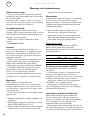
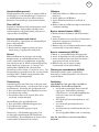
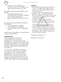
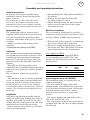
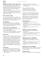
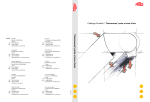
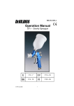
Comfortline AZR SE .... 10 GB .... 15 Comfortline AZR E/W Dimensions [mm] FRONT (AZR1000, AZR1500, AZR2000) SIDE 549 A B 236 C AZR2000 Ø20 (4x) 220 Ø32 (1x) DN20 (3/4”) (2x) DN20 (3/4”) (2x) 602 D FROM ABOVE Only valid for AZR2000W 27 AZR2000 AZR2000 9 Type A B C D AZR1000E/W AZR1500E/W AZR2000E/W [mm] 1000 1500 2000 [mm] 960 1460 1960 [mm] 389 760 1338 [mm] 1052 1552 2052 2 Type Suspension points [pcs] AZR1000E/W AZR1500E/W AZR2000E AZR2000W 4 4 6 7 Comfortline AZR E/W Mounting AZR2000 Only valid for AZR2000W M8 Fig. 1: Mounted with M8 bolts. Fig. 2: How to open the maintenance hatch. 3 Comfortline AZR E/W Water regulators VR20/25 AV20/25 BPV10 TRV20/25 SD20 VR20/25 JVF20/25 TVV20/25 Accessories Type VR20 VR25 Description Set of valves DN20 (3/4”) Set of valves DN25 (1”) TVV20 TVV25 SD20 2-way valve DN20 (3/4”) 2-way valve DN25 (1”) Actuator on/off (”soft closing”) AV20/25 JVF20/25 TRV20/25 BPV10 TVV20/25 SD20 SD20 Air curtain Air curtain Controls Controls D705IR D700e Accessories Type D705IR 4 Description 5 step regulation of airflow (Included in delivery) Accessories Type D700e Description 3 step regulation of airflow and heat output (Included in delivery) Comfortline AZR E/W Wiring diagrams AZR E Internal Comfortline AZR E *1 For connection to slave unit. Up to 4 units can be connected to one control unit. Bridge C1 and 5 in all units. C4-C5 Reomve bridge to connect external contact. It switches both heating and fans. Closed contact=on. J5-J6 Not used. 5 Comfortline AZR E/W Wiring diagrams AZR W Water control Comfortline AZR W 6 Comfortline AZR E/W Output charts water Type AZR1000 AZR1500 AZR2000 Type AZR1000 AZR1500 AZR2000 Type AZR1000 AZR1500 AZR2000 Type AZR1000 AZR1500 AZR2000 Incoming / outgoing water temperature 80/60°C Air temp. in = +15°C Air temp. in = +20°C Incoming water: 80°C*1 Fan Airflow Output Return Water Output Air.temp. Water Output Air.temp. Water position [m3/h] [kW] water flow [kW] out flow [kW] out flow o [l/s] [°C] [l/s] [ C] [l/s] [°C] high med low high med low high med low 2700 2030 1350 3600 2700 1800 5400 4050 2700 13,7 10,4 6,6 18,4 13,8 9,4 27,6 20,5 14,3 46 41 36 32 29 27 32 29 30 0,09 0,06 0,04 0,09 0,07 0,04 0,14 0,10 0,07 23,3 19,6 15,1 34,6 29,2 22,5 54,0 45,4 35,1 41 44 49 44 47 53 45 49 54 0,28 0,24 0,18 0,42 0,36 0,27 0,66 0,55 0,43 21,0 17,7 13,7 31,3 26,4 20,4 48,9 41,2 31,8 43 46 50 46 49 54 47 51 55 0,26 0,22 0,17 0,38 0,32 0,25 0,60 0,50 0,39 Incoming / outgoing water temperature 70/50°C Air temp. in = +15°C Air temp. in = +20°C Incoming water: 70°C*1 Fan Airflow Output Return Water Output Air.temp. Water Output Air.temp. Water position [m3/h] [kW] water flow [kW] out flow [kW] out flow [l/s] [°C] [l/s] [oC] [l/s] [°C] high med low high med low high med low 2700 2030 1350 3600 2700 1800 5400 4050 2700 13,7 10,3 6,8 18,2 13,5 9,2 27,0 20,2 13,9 40 36 33 35 31 28 34 31 30 0,11 0,07 0,04 0,13 0,08 0,05 0,18 0,12 0,08 18,5 15,6 12,1 27,8 23,4 18,1 43,3 36,5 28,2 35 38 42 38 41 45 39 42 46 0,23 0,19 0,15 0,34 0,29 0,22 0,53 0,44 0,34 16,3 13,7 10,6 24,5 20,6 16,0 38,0 32,0 24,8 38 40 44 40 43 47 41 44 48 0,20 0,17 0,13 0,30 0,25 0,19 0,46 0,39 0,30 Incoming / outgoing water temperature 70/40°C Air temp. in = +15°C Air temp. in = +20°C Incoming water: 70°C*1 Fan Airflow Output Return Water Output Air.temp. Water Output Air.temp. Water position [m3/h] [kW] water flow [kW] out flow [kW] out flow o [l/s] [°C] [l/s] [ C] [l/s] [°C] high med low high med low high med low 2700 2030 1350 3600 2700 1800 5400 4050 2700 13,7 10,3 6,8 18,2 13,5 9,2 27,0 20,2 13,9 40 36 33 35 31 28 34 31 30 0,11 0,07 0,04 0,13 0,08 0,05 0,18 0,12 0,08 21,0 17,7 13,7 23,1 19,5 15,0 35,5 29,9 23,1 43 41 45 34 37 40 35 37 41 0,26 0,22 0,17 0,19 0,16 0,12 0,29 0,24 0,19 12,7 10,7 8,3 19,7 16,6 12,8 30,2 25,4 19,6 34 36 38 36 38 41 37 39 42 0,10 0,09 0,07 0,16 0,13 0,10 0,24 0,21 0,16 Incoming / outgoing water temperature 60/40°C Air temp. in = +15°C Air temp. in = +20°C Incoming water: 60°C*1 Fan Airflow Output Return Water Output Air.temp. Water Output Air.temp. Water position [m3/h] [kW] water flow [kW] out flow [kW] out flow [l/s] [°C] [l/s] [oC] [l/s] [°C] high med low high med low high med low 2700 2030 1350 3600 2700 1800 5400 4050 2700 *1) Air temperature in/out: 13,9 10,5 6,9 18,0 13,7 9,2 27,7 20,3 13,9 44 40 35 38 35 31 38 34 31 0,21 0,13 0,07 0,20 0,13 0,08 0,31 0,19 0,12 13,9 11,7 9,0 21,0 17,7 13,7 32,4 27,3 21,1 30 32 35 32 35 38 33 35 39 0,17 0,14 0,11 0,26 0,22 0,17 0,39 0,33 0,25 11,6 9,7 7,5 17,6 14,8 11,5 27,1 22,8 17,7 33 34 37 35 37 39 35 37 40 0,14 0,12 0,09 0,21 0,18 0,14 0,33 0,28 0,21 18 / 33 oC. 7 Comfortline AZR E/W Pressure drop water Water pressure drop over AZR water coil 1,0 10 0,7 10 0,1 0 R2 00 AZ AZ A R1 00 ZR15 0 00 Pressure drop [kPa] 0,1 70 Pressure drop [bar] Water flow [m³/h] 0,01 1 0,01 0,1 1,0 70 Waterflow [m3/h] 10 0.7 10 0.1 1.0 V 0.1 V Pressuredrop [kPa] Water pressure drop over controls and valves 1 0.01 0.1 1.0 0.01 Waterflow [l/s] The pressure drop is calculated for an average temperature of 70°C (PVV 80/60). For other water temperatures, the pressure drop is multiplied by the factor K. Average temp. water °C 40 K 1,10 8 50 1,06 60 1,03 70 1,00 80 0,97 90 0,93 Pressuredrop [bar] Water flow [l/s] Comfortline AZR E/W Technical specifications | Type AZR1000E AZR1500E AZR2000E Output steps [kW] 5/10/15 7,5/15/22,5 10/20/30 Airflow ∆t*¹ [m³/h] 1350/2700 1800/3600 2700/5400 [°C] 33/17 37,5/19 33/17 Technical specifications | Type Output*3 [kW] AZR1000W 15,5 AZR1500W 20,6 AZR2000W 29,8 AZR E Sound level*² [dB(A)] 40/58 41/59 43/61 Voltage Amperage (control) 230 V~ / 3,4 A 230 V~ / 4,5 A 230 V~ / 6,7 A Voltage Amperage (heat) 400 V3~ / 22,0 A 400 V3~ / 32,5 A 400 V3~ / 43,5 A Weight [kg] 50 80 110 Sound level*² [dB(A)] 40/58 41/59 43/61 Voltage Amperage Weight [V] 230 V~ 230 V~ 230 V~ [A] 3,4 A 4,5 A 6,7 A [kg] 50 80 110 AZR W Airflow ∆t*¹,*³ [m³/h] 1350/2700 1800/3600 2700/5400 [°C] 33/17 34/17 33/17 Protection class AZR E/W: IP23. GB *1) ∆t = temperature rise of passing air at maximum heat output and lowest/highest airflow. *2) Conditions: Distance to the unit: 5 metres. Directional factor: 2. Equivalent absorption area: 200 m2. *3) Applicable at water temperature 80/60 °C, air temperature, in +15 °C. 9 SE Comfortline AZR E/W Montage- och bruksanvisning Allmänna anvisningar Läs noga igenom denna bruksanvisning före installation och användning. Spara manualen för framtida bruk. Garantin gäller endast om Frico montageoch bruksanvisning har följts och produkten använts såsom däri är beskrivet. Användningsområde Luftridåaggregatet AZR levereras med elvärme- eller varmvattenbatteri och är avsett som skydd för entrédörrar och mindre portar upp till 3,5 meters höjd. AZR monteras dold i undertak ovanför entrén. Kapslingklass: IP23. Funktion Luften sugs in underifrån och blåses ut neråt så att den skärmar av öppningen och minimerar värmeläckage genom den. För bästa ridåverkan ska aggregaten täcka hela öppningens bredd. Gallret som riktar luften är justerbart och vrids normalt något utåt så att luftstrålen hindrar den inkommande kalla luften. Lufthastigheten justeras till önskat luftflöde. Luftridåns effektivitet beror på hur stor belastningen är på den aktuella porten. Observera att undertryck i lokalen försämrar luftridåns effektivitet väsentligt. Ventilationen bör därför vara balanserad! Montering AZR monteras horisontellt med utblåsriktningen nedåt så nära porten som möjligt, dold i undertak. Det enda som syns är underdelen av apparaten som ligger i nivå med undertaket. Se till att serviceluckan är åtkomlig och kan öppnas helt. 1.Upphängningsbultarna (M8) medföljer vid transport. 2.Häng upp på aggregatet med hjälp av dessa bultar (M8) enligt figur 2 på s.3. 3.Justera höjden med muttern som medföljer vid leverans, så att ramen är i nivå med 10 undertaket. Lås sedan muttern. Elinstallation Installationen, som ska föregås av en allpolig brytare med ett brytavstånd om minst 3mm, ska utföras av behörig installatör och i enlighet med denna bruksanvisning samt gällande föreskrifter. 1.Serviceluckan öppnas genom att lossa skruvarna på aggregatets undersida. 2.Aggregatet ansluts via hål på aggregatets sida. Använda kabelgenomföringar måste säkerställa kravet på kapslingsklass. Gäller endast AZR E Anslutning görs med kabel av typ EKK, EKLK eller motsvarande. Använda kabelgenomföringar måste säkerställa kravet på kapslingsklass. Typ AZR1000E AZR1500E AZR2000E Effekt [kW] 15 22,5 30 Spänning [V] 400V3~ 400V3~ 400V3~ Minimiarea [mm2] 6 10 16 Anslutning av vattenbatteri (AZR W) Installationen skall utföras av behörig installatör. Vattenbatteriet består av kopparrör med flänsar av aluminium och är avsett att användas i ett slutet system. Batteriet får inte anslutas till färskt eller syresatt vatten. Aggregatet ansluts via hål på aggregatets sida(DN20, 3/4", invändig gänga). Anslutningarna till batteriet ska förses med avstängningsventiler för att möjliggöra problemfri demontering. lnjustering av luftridån och luftström Luftstrålens riktning och hastighet ska justeras med hänsyn till belastningen på porten. Tryckkrafter påverkar luftströmmen så att den böjer av inåt i lokalen (vid uppvärmd lokal och kall uteluft). Luftströmmen bör därför riktas utåt för att stå emot belastningen. Generellt kan sägas att ju större belastning desto större vinkel krävs. Comfortline AZR E/W Grundinställning varvtal Fläkthastigheten då porten är öppen ställs in med hjälp av varvtalsregleringen. Observera att utblåsriktning och varvtal kan behöva finjusteras beroende på portens belastning. Filter (AZR W) Batteriets lamellavstånd i kombination med håldiametern i insugsgallret skyddar mot nedsmutsning och igensättning och gör ett separat filter överflödigt. Service, reparation och skötsel Vid all service, reparation och underhåll gör först enligt följande: 1.Bryt strömmen. 2.Serviceluckan öppnas genom att lossa skruvarna på aggregatets undersida. Skötsel Eftersom fläktarnas motorer och övriga komponenter är underhållsfria krävs inget annat underhåll än regelbunden rengöring, hur ofta beror på de lokala omständigheterna dock minst två gånger per år. Insugs- och utblåsgaller, fläkthjul och element kan dammsugas eller torkas av med torr trasa. Vid dammsugning använd borste för att inte skada ömtåliga delar. Undvik starkt basiska eller syrahaltiga rengöringsmedel. Överhettning Luftridåaggregat med elvärme är försett med temperaturbegränsare. Om den har löst ut pga överhettning, återställs den på följande sätt: 1.Bryt strömmen med den allpoliga brytaren. 2.Låt elbatteriet svalna. 3.Fastställ orsaken och åtgärda felet som orsakade överhettningen. Återställning görs på följande sätt: 1.Bryt strömmen till luftridåaggregatet. 2.Låt elbatteriet svalna. 3.Koppla in luftridåaggregatet igen. Motorerna, i alla luftridåaggregaten, har en inbyggd termokontakt till skydd mot överhettning. Återställningen av denna sker automatiskt då motorn har svalnat. SE Fläktbyte 1.Undersök vilken av fläktarna som inte fungerar. 2.Lossa kablarna till fläkten. 3.Lossa fläktens fästskruvar och lyft ut fläkten. 4.Montera den nya fläkten enligt ovanstående i omvänd ordning. Byte av elbatteri/batteri (AZR E) 1.Märk och lossa kablarna till elelementet/ batteriet. 2.Lossa fästskruvarna som låser elelementet/ batteriet i aggregatet och lyft ut elelementet/batteriet. 3.Montera det nya elelementet/batteriet enligt ovanstående i omvänd ordning. Byte av vattenbatteri (AZR W) 1.Stäng av vattentillförseln till aggregatet. 2.Lossa anslutningarna till vattenbatteriet. 3.Lossa fästskruvarna som låser batteriet i aggregatet och lyft ut batteriet. 4.Montera det nya batteriet enligt ovanstående i omvänd ordning. Tömning av vattenbatteriet (AZR W) Tömningsventilen sitter undertill på batteriet på anslutningssidan. Den nås via serviceluckan. Felsökning Om fläktarna inte går eller inte blåser tillräckligt, kontrollera följande: • Att manöverspänning finns fram till aggregatet; kontrollera säkringar, arbetsbrytare, eventuellt kopplingsur/ termostat som startar/stoppar aggregatet. • Att eventuell varvtalsreglering är rätt inställd. • Att eventuell gränslägesbrytare fungerar. • Att motorernas termokontakt inte har löst ut. • Att insugsgallret/filtret inte är smutsigt. Om det inte blåser varmt, kontrollera följande: 11 SE Comfortline AZR E/W • Kontrollera att inställningar av termostat, brytare etc är ställda så att apparaten kan förväntas ge värme. För aggregat med elvärme kontrollera även följande: • Att spänning finns fram till elvärmebatteriet; kontrollera säkringar och eventuell arbetsbrytare. • Att överhettningsskyddet inte har löst ut. För aggregat med vattenbatteri kontrollera även följande: • Att vattenbatteriet är avluftat. • Att vattenflödet är tillräckligt. • Att inkommande vatten är tillräckligt varmt. Om felet inte kan avhjälpas, tag kontakt med behörig servicetekniker. Säkerhet • Säkerställ att området kring apparatens insugs- och utblåsgaller hålls fritt från material som kan hindra luftströmmen genom apparaten! • Apparaten kan vid drift ha heta ytor! • Apparaten får ej övertäckas helt eller delvis med kläder eller dylikt material, då överhettning av apparaten kan medföra brandfara! (AZR E) • Denna produkt är inte avsedd att användas av barn eller personer med nedsatt fysisk eller mental förmåga eller brist på erfarenhet och kunskap, om inte anvisningar angående produktens användning har getts av person med ansvar för deras säkerhet eller att denna person övervakar handhavandet. Barn skall hållas under uppsikt så att de inte kan leka med produkten. Tekniska data finns på s.9. Jordfelsbrytare (gäller aggregat med elvärme) Om installationen är skyddad av jordfelsbrytare och denna löser ut vid inkopplingen av elaggregat kan detta bero på fukt i värmeelementen. När ett aggregat som innehåller värmeelement inte använts under en längre tid eller lagrats i fuktig miljö kan fukt tränga in. Detta är inte att betrakta som ett fel utan åtgärdas enklast genom att tillfälligt låta aggregatet matas utan föregående jordfelsbrytare så att elementen torkar. Torktiden kan variera från någon timma till ett par dygn. l förebyggande syfte är det lämpligt att anläggningen tas i drift kortare stunder under längre användningsuppehåll. 12 Reglering, se nästa sida. Comfortline AZR E/W SE Reglering Reglering D700e Regleringen styr den anslutna luftridåns olika fläktläge och värmesteg. Om agregatet är avstängd väljs fläktläge 1 med ett tryck på knappen ”FAN SELECT”. Med ytterligare tryck på denna knapp väljs nästa högre fläktsteg. När fläktsteg 3 har nåtts, stegar man nedåt i fläktsteg med ytterligare på denna knapp. Om knappen trycks en gång till efter att fläktsteg 1 har nåtts stängs agregatet av. Det inställda fläktläget visas med en lysdiod. När agregatet är avstängt lyser lysdioden ”OFF”. Efter att fläktläget har valts kan man välja värmesteg genom att trycka på knappen ”HEATING SELECT”. Precis som med fläktläge väljer man nästa värmesteg genom ytterligare tryck. Det är inte möjligt att välja ett värmesteg som är högre än fläktläget. Om man, till exempel, när värmesteg 3 och fläktläge 3 har valts, sänker fläktläge från 3 till 2, kommer även värmesteget att sänkas från 3 till 2. Valt värmesteg visas med en lysdiod. Lysdioden ”OFF” lyser när inget värmesteg har valts. Om en signal från eftergångstermostaten detekteras efter att luftridån stängts av startas fläktarna igen och körs tills ridån har svalnat. Att eftergångstiden är aktiv indikeras genom att lysdioden för fläktsteg 3 blinkar. D705IR Manuell styrning Kontrollboxen har 2 knappar för att höja och sänka respektive steginställning för fläkthastigheten, 0-1-2-3-4-5. Det valda steget visas med LED-indikering. Om en magnetventil eller en elektrisk motor ventil är inkopplad till luftridåns interna kretskort, kan den tredje knappen kontrollera sommar/vinter (värme av/på) läget. Om fläktarna är avstängda genom att välja fläktsteg 0/Off, så bryts värmetillförseln av automatiskt. Värmen tillförs igen när en fläkthastighet är vald. Likadana knappar finns på IR-fjärrkontrollen, IR01 (Tillbehör som finns tillgängligt på vissa marknader). Automatisk styrning Kontrollboxen är utrustad med en potentialfri kontakt, vilket möjliggör att lufridån kan styras automatiskt med hjälp av en dörrkontakt, rumstermostat eller ett BMS system. Enheten är i drift när dörren är öppen, när rumstermostaten eller antingen BMS systemet skickar en startsignal, då öppnas den potetntialfria kontakten, erfordelig fläkthastighet kan aktiveras på kontrollen. Inne i kontrollboxen kan man genom en DIPswitch justera den potentialfria kontaktens funktion när den är stängd, genom att den antingen helt stänger av enheten eller är i drift på lågfart. Switchen är i On position: Lufridån skiftar mellan On/Off. Switchen i Off position: Luftridån skiftar mellan lågfart/högfart. För att undvika frekvent byte av fläkthastigheten kan en eftergångstid ställas in (15-75 s). 13 SE Comfortline AZR E/W Vattenreglering VR 20/25, ventilsats Används för reglering av vattenflödet till vattenvärmda aggregat. Ventilsatsen består av följande: • AV20/25, avstängningsventil • JVF20/25, injusteringsventil • TRV20/25, trevägsventil • BPV10, by-passventil • SD20, ställdon on/off 230V~ (mjukstängande) Avstängningsventilen (AV20/25) består av en kulventil som antingen är öppen eller stängd och används för att kunna stänga av flödet, t.ex. vid service. Med injusteringsventilen kan flödet finjusteras manuellt eller stängas av helt. Det injusterade vattenflödet kan avläsas direkt på ventilen. JVF20 har kvvärde 3,5 och JVF25 har kv-värde 5,5. Om trevägsventilen (TRV20/25) är stängd, passerar ett lågt flöde genom by-passventilen (BPV10) för att det alltid ska finnas varmt vatten i värmebatteriet. Detta för att ge en snabb värmetillförsel t.ex. när en port öppnas samt för ett visst frysskydd. Ställdonet (SD20) reglerar värmetillförseln on/off. Ventilsatsen finns med två olika dimensioner på ventilerna. VR20 har DN20 (3/4”) och VR25 har DN25 (1”). By-passventilen har DN10 (3/8”). Illustration s.4. 14 TVV20/25, 2-vägs reglerventil TVV20 har dimension DN20 (3/4”) och TVV25 dimension DN25 (1”). Tryckklass PN16. Maximalt tryck 2 MPa (20 bar). Maximalt tryckfall TVV20: 100 kPa (0,1 bar) Maximalt tryckfall TVV25: 62 kPa (0,062 bar) Kv-värdet är ställbart i tre lägen: TVV20 TVV25 Pos 1 kv 1,6 kv 2,5 Pos 2 kv 2,5 kv 4,0 Pos 3 kv 3,5 kv 5,5 SD20, ställdon on/off 230V~ (mjukstängande) För reglering av värmetillförseln. Arbetar on/off. Cykel-tiden mellan stängt och öppet på fem sekunder förhindrar tryckslag i rörsystemet. Kapslingsklass: IP40. TVV20/25 och SD20 ger en enklare variant av vattenreglering, utan möjligheter att justera eller stänga av vattenflödet vid t.ex. service. Illustration s.4. TE3434 Flexibel slang, längd 0,8 meter, för vattenanslutna aggregat (det behövs två slangar till varje aggregat) med utvändig gänga 3/4" (DN20) i ena änden och kopplingsmutter med invändig gänga 3/4" (DN20) i den andra. Comfortline AZR E/W GB Assembly and operating instructions General Instructions Read these instructions carefully before installation and use. Keep this manual for future reference. The guarantee is only valid if the units are used in the manner intended by the manufacturer and in accordance with the Frico mounting and operating instructions. Application area The Comfortline AZR air curtain unit is supplied with electrical heating or hot water coil and is intended for installation above entrances and smaller doors up to 3.5 metres in height. AZR is recessed in false ceilings above entrances. Protection class above roof: IP23, Operation Air is drawn in from underneath and blown out downwards towards the entrance so that it shields the door opening and minimises heat loss. To get the best curtain effect the unit must extend the full width of the door opening. The grille for directing exhaust air is adjustable and is normally angled outwards to achieve the best protection against incoming cold air. The air speed is adjusted to the desired airflow. The efficiency of the air curtain(s) depends on the air temperature, pressure differences across the doorway and any wind pressure. NOTE! Negative pressure in the building considerably reduces the efficiency of the air curtain. The ventilation should therefore be balanced! Installation AZR unit is installed horizontally with the supply air grille facing downwards as close to the door as possible, concealed in the false ceiling. The only visible part of the unit is the underside that is level with the ceiling. Ensure that the service hatch is accessible and can be fully opened. 1.The mounting bolts (M8) will be included in the delivery. 2.Hang up the unit with the bolts (M8) according to figure 2 on p.3. 3.Adjust the height using the nut so that the frame is on the same level as the ceiling. Lock using the nut. Electrical installation The air curtain(s) should only be wired by a competent electrician and in accordance with the latest edition of IEE wiring regulations. 1.The service hatch is opened by screwing off the screws on lower body of the unit . 2.The unit is supplied through holes on the side of the unit. The cable glands used must meet the protection class requirements. Only applies to AZR E Connections are made using EKK, EKLK or corresponding type cables. The cable glands used must meet the protection class requirements. Type Output [kW] Voltage [V] AZR1000E AZR1500E AZR2000E 15 22,5 30 400V3~ 400V3~ 400V3~ Minimum area [mm2] 6 10 16 Connecting the water coil (AZR W) The installation must be carried out by an authorised installer. The water coil has copper tubes with aluminium fins and is suitable for connection to a closed water heating system. The heating coil must not be connected to a mains pressure water system or an open water system. The unit is supplied through holes on the side of the unit (DN20, 3/4”). The connections to the heating coil must be equipped with shut off valves to allow problem free removal. 15 GB Comfortline AZR E/W Adjustment of the air curtain and air flow The direction and speed of the air flow should be adjusted considering the load on the opening. Pressure forces affect the air stream and make it bend inwards into the premises (when the premises are heated and the outdoor air is cold). The air stream should therefore be directed outwards to withstand the load. Generally speaking, the higher the load, the greater the angle that is needed. Basic setting fan speed The fan speed when the door is open is set using the speed control. Note that the air flow direction and speed may need fine adjustment depending on the loading of the door. Filter (AZR W) The heat coil fin distance, in combination with the hole diameter of the intake grille, protects against dirt and blockage and makes a separate filter unnecessary. Service, repairs and maintenance For all service, repair and maintenance first carry out the following: 1.Disconnect the power supply. 2.The service hatch is opened by screwing off the screws on the underside of the unit. Maintenance Since fan motors and other components are maintenance free, no maintenance other than cleaning is necessary. The level of cleaning can vary depending on local conditions. Undertake cleaning at least twice a year. Inlet and exhaust grilles, impeller and elements can be vacuum cleaned or wiped using a damp cloth. Use a brush when vacuuming to prevent damaging sensitive parts. Avoid the use of strong alkaline or acidic cleaning agents. Overheating The air curtain unit with electric heater is equipped with an overheat protector. If it is deployed due to overheating, reset as follows: 1.Disconnect the electricity with the fully isolated switch. 16 2.Allow the electrical coil to cool. 3.Determine the cause of overheating and rectify the fault. Reset is performed as follows: 1.Disconnect the power supply. 2.Allow the electrical coil to cool. 3.Reconnect the air curtain again. All motors are equipped with an integral thermal safety cut-out. This will operate, stopping the air curtain should the motor temperature rise too high. The cut-out will automatically reset when the motor temperature has returned to within the motor's operating limits. Fan replacement 1.Determine which of the fans is not functioning. 2.Disconnect the cables to the relevant fan. 3.Remove the screws securing the fan and lift the fan out. 4.Install the new fan as above in reverse order. Replacing the electric coil (AZR E) 1.Mark and disconnect the cables to the electric coil. 2.Remove the mounting screws securing the coil in the unit and lift the coil out. 3.Install the new coil in reverse order to the above. Replacing the water coil (AZR W) 1.Shut off the water supply to the unit. 2.Disconnect the connections to the water coil. 3.Remove the mounting screws securing the coil in the unit and lift the coil out. 4.Install the new coil in reverse order to the above. Draining the water coil (AZR W) The drain valve is on the underside of the coil on the connector side. It can be accessed via the service hatch. Trouble shooting If the fans are stationary, check the following: Comfortline AZR E/W 1.Operating power supply to the unit; check fuses, circuit-breaker, time switch/ thermostat (if any) that starts and stops the unit. 2.That the air flow selector is correctly set. 3.That the position limit switch is working. 4. That the overheat protection for the motors has not been deployed. 5.That the intake grille is not dirty. AZR E If there is no heat, check the following: 1.Power supply to electric heater coil; check fuses and circuit-breaker (if any). 2.That the heat demand exists; check thermostat settings and actual temperature. 3.That the intake grille is not dirty. GB occasionally be run for a short time when it is not being used for extended periods of time. Safety • Keep the areas around the air intake and exhaust grilles free from possible obstructions! • During operation the surfaces of the unit are hot! • The unit must not be fully or partially covered with clothing, or similar materials, as overheating can result in a fire risk! (AZR E) Technical data is on p. 9. Regulation, see next page. AZR W If there is no heat, check the following: 1.That there is hot water to the water coil. (Check the circulation pump - if applicable.) 2.That the heat demand exists; check thermostat settings and actual temperature. 3.That the intake grille is not dirty. If the fault cannot be rectified, please contact a qualified service technician. Safety cut-out (applies to units with electric heater) If the installation is protected by means of a safety cut-out, which trips when the appliance is connected, this may be due to moisture in the heating element. When an appliance containing a heater element, has not been used for a long period and is stored in a damp environment, moisture can enter the element. This should not be seen as a fault, but is simply rectified by connecting the appliance to the mains supply via a socket without a safety cut-out, so that the moisture can be driven out of the element. The drying time can vary from a few hours to a few days. As a preventive measure the unit should 17 GB Comfortline AZR E/W Regulation Regulation D700E This regulator controls the various ventilation D700e Standard regulation for electrically heated units • This regulator controls the various ventilation and heating stages of the connected air curtain directly. • If the unit is switched off, fan stage 1 is switched on by pushing button “FAN SELECT”. By pushing this button again the next higher fan stage is switched on. • After reaching fan stage 3 the fan stages are switched back down by pushing this button again. When fan stage 1 is reached and the button is pushed again the unit is switched off. The set fan stage is indicated by an LED. When the unit is switched off the LED "OFF" is lit. • After setting a ventilation stage, it is possible to set a heating stage by pushing button “HEATING SELECT”. Here, to the next higher heating stage is set by pushing this button again. It is not possible to set a heating stage which is higher than the set ventilation stage. • If, for example, when heating stage 3 and ventilation stage 3 are set, the ventilation stage is switched back from 3 to 2, the heating stage is automatically also switched from stage 3 to stage 2. The set heating stage is indicated by an LED. The LED "OFF" is lit when no heating stage is set. • Should there be a signal from the followup thermostat after switching off the unit, the fans are switched on again until the unit is cooled down. This follow-up function is indicated by blinking of LED fan stage 3. D705IR Manual control The controller has 2 buttons for up and down respectively, for setting the steps 0-1-2-3-4-5, controlling the air volume. The set step is shown with LED-lights. If a solenoid valve or thermo-electrical actuator is connected to the internal PCboard of the air curtain the third button can control the summer/winter (off/on) switching of the heating medium supply. If the fans are shut off by selecting step 0 / OFF the heating medium supply is automatically closed. It is opened again when the unit is started again. The same buttons can be found on the IRremote controller IR01 (accessory on some markets). Automatic control The controller is equipped with a terminal for a potential free contact through which the air curtain can be automatically controlled, i.e. with a door contact, a room thermostat or a BMS system. When the unit is to run, when the door is open or when either a room thermostat or BMS is giving a start signal, the potential free contact should be open and the required fan step can be set on the controller. The controller can be adjusted through a DIPswitch inside the controller whether to shut off completely or to run on lowest speed when the potential free contact closes. Switch in position On: Air curtain switches on/off. Switch in position Off: Air curtains switches between low/high speed. To avoid frequent switching of the fan speed an overrun time between 15 and 75 s can be set on the controller. 18 Comfortline AZR E/W GB Water control VR20/25, set of valves Used to control the water supply to water heated units. The valve set consists of the following: • AV20/25, stop valve • JVF20/25, adjustment valve • TRV20/25, 3-way control valve • BPV10, bypass valve • SD20, actuator on/off 230V~ (soft closing) The stop valve (AV20/25) consists of a ball valve which is either open or closed and is used to shut off the flow, when servicing for example. The adjustment valve can be used to finely adjust or shut off the water flow manually. The adjusted water flow can be read directly off the valve. JVF20 has a kv value of 3.5 and JVF25 has a kv value of 5.5. If the three way valve (TRV20/25) is closed, a low flow passes through the by-pass valve (BPV10) so that there is always warm water in the water coil. This is to provide quick heat supply when a door is opened but also to provide a degree of frost protection. Actuator (SD20) controls the heat supply on/off. The valve set has two different sizes in the valves. VR20 is DN20 (3/4") and VR25 is DN25 (1"). The by-pass valve is DN10 (3/8"). See illustrations page 4. TVV20/25, 2-way control valve TVV20 is DN20 (3/4”) in size and TVV25 is DN25 (1”) in size. Pressure class PN16. Maximum Pressure 2 MPa (20 bar). Maximum pressure drop TVV20: 100 kPa (0.1 bar) Maximum pressure drop TVV25: 62 kPa (0.062 bar) The Kv value can be set to three positions: Pos 1 TVV20 kv 1.6 TVV25 kv 2.5 Pos 2 kv 2.5 kv 4.0 Pos 3 kv 3.5 kv 5.5 SD20, actuator on/off 230V~ (soft closing) For control of the water supply. Works on/off. A 5 second cycle of opening and closing of the valve prevents sudden pressure changes in the pipe system. Protection class: IP40. TVV20/25 and SD20 give a simplified variant of water control without the possibillity to adjust or shut down the water flow (for mainteneance or replacemnet of coil). See illustrations page 4. TE3434 Flexible hose, length 0.8 metres, for water connected units (two hoses are required for each unit) with 3/4" (DN20) external thread at one end and a connection nut with 3/4" (DN20) internal thread at the other. 19 Main office Frico AB Tel: +46 31 336 86 00 Box 102 Fax: +46 31 26 28 25 SE-433 22 Partille [email protected] Swedenwww.frico.se Norway Frico AS Tel: +47 23 37 19 00 P.B 82 Alnabru Fax: +47 23 37 19 10 NO-0614 Oslo [email protected] Norwaywww.frico.no France Frico SAS Tel: +33 4 72 42 99 42 53 avenue Carnot Fax: +33 4 72 42 99 49 69250 Neuville sur Saône [email protected] Francewww.frico.fr Spain Frico repr. office in Spain Tel: +34 91 887 60 00 C/. Cabeza de hierro, 39 Fax: +34 91 887 60 00 ES-28880 Meco [email protected] Spainwww.frico.se United Kingdom Frico Limited Tel: +44 (0)121 322 0854 72 Cheston Road Fax: +44 (0)121 322 0858 B7 5EJ [email protected] UK-Birminghamwww.frico.co.uk United Kingdom Russia Frico repr. office in Russia Tel: +7 495 238 63 20 Lavrov per. 6 +7 495 676 44 48 RU-109044 Moscow Fax: +7 495 676 44 48 [email protected] www.frico.se China Frico repr. office in China Rm 702, Modern Comm. Build. 201, New Jin qiao Rd 201206 Shanghai P.R. China Tel: +86 21 62569900 Fax:+86 21 62554747 [email protected] www.frico.com.cn Switzerland Gutekunst AG Tel: 061 706 96 26 (nat) Baselstrasse 22 Fax: 061 706 96 20 (nat) CH-4144 Arlesheim [email protected] Switzerlandwww.gutekunst-ag.ch For latest updated information, see: www.frico.se Art.no AZR, 20080514 HM Austria Frico GmbH AT Tel: +43 1 616 24 40-0 Kolpingstraße 14 1232 Wien [email protected] Austriawww.fricogmbh.at