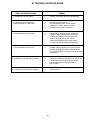
1
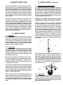
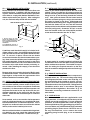
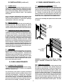
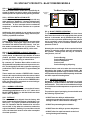
Quality Refrigeration
OWNER’S MANUAL
Instructions for the installation
and maintenance of most Traulsen models as well as
instructions to operate the following special models:
Blast Freezer Models
RBF134HUT-FHS (formerly RIF134HUTBF) & RBF234HUT-FHS (formerly RIF234HUTBF)
Fish File Models
RFS126NUT, RFS226NUT & RFC232WSC
This Traulsen unit is built to our highest quality standards. We build our refrigerators, freezers and heated
cabinets this way as a matter of pride. This philosophy has made Traulsen the leader in commercial refrigeration since 1938. We thank you for your choice and confidence in Traulsen equipment and we know you
will receive many years of utility from this equipment.
All Traulsen units are placed on a permanent record file with the service department. In the event of any
future questions you may have, please refer to the model and serial number found on the name tag affixed
to the unit. Should you need service, however, call us on our toll free number, 800-825-8220 between 7:30
am and 4:30 pm CST, Monday thru Friday. It is our pleasure to help and assist you in every possible way.
INSTALLER
COMPLETE THE FOLLOWING INFORMATION PRIOR TO UNIT INSTALLATION
INITIAL START DATE:
SERIAL NO.
MODEL TYPE:
COMPANY/INDIVIDUAL NAME:
INSTALLER:
FORM NUMBER TR35750 REV. 7/05
P/N 375-60185-00
TABLE OF CONTENTS
I. THE SERIAL TAG
II. RECEIPT INSPECTION
III. INSTALLATION
a-Location
b-Packaging
c-Installing Legs or Casters
d-Shelf Pins
e-Roll-In Model Installation
f-Installing The Condensate Evaporator
g-Remote Installation
h-Cord & Plug
i-Power Supply
j-Wiring Diagram
k-Compressor Hold Down Provisions
l-Clearance
IV. CARE & MAINTENANCE
a-Cleaning The Condenser
b-Hinge Replacement
c-Replacing The Gaskets
d-Cleaning The Exterior
e-Cleaning The Interior
V. MISC. OPERATIONS
a-Adjusting The Shelves
VI. OTHER
a-Service Information
b-Spare Parts
c-Warranty Registration
Page 1
Page 2
VII. FISH FILE MODELS
a-Fish File Application
b-Special Installation Note
c-Drawer Pans
d-Product Loading
e-Cleaning
VIII. BLAST FREEZER MODELS
a-Blast Freezer Application
b-Special Installation Note
c-Interior Arrangements
d-Blast Freezing vs. Blast Chilling
e-Normal Operation
f-Defrost
g-Blast Chill Operation
h-Proper Packaging
IX. STAINLESS STEEL OVERVIEW
a-Introduction
b-Stainless Steel, How It Works
c-Understanding The Causes of Corrosion
X. CARE OF STAINLESS STEEL
a-Using The Proper Tools
b-Using The Right Cleanser
c-Cleaning Do’s and Don’ts
XI. CORROSION REMEDIES
a-Dealing With Rust After The Fact
b-Dealing With Extreme Rust Situations
c-Restoring The Protective Layer
XII. TROUBLE SHOOTING GUIDE
XIII. WARRANTY INFORMATION
Page 2
Page 2
Page 2
Page 2
Page 3
Page 3
Page 3
Page 3
Page 4
Page 4
Page 4
Page 4
Page 4
Page 4-5
Page 5
Page 5
Page 5
Page 5
Page 5
Page 5
Page 5
Page 6
Page 6
Page 6
Page 6
Page 6
Page 7
Page 7
Page 7
Page 7
Page 7
Page 7
Page 7
Page 7
Page 8
Page 8
Page 8
Page 8
Page 8
Page 9
Page 9
Page 9
Page 9
Page 10
Back Cover
I. THE SERIAL TAG
FORT WORTH, TX.
SERIAL
VOLTS
MODEL
Hz
PH
TOTAL CURRENT
AMPS
MINIMUM CIRCUIT
AMPS
MAXIMUM OVERCURRENT PROTECTION
LIGHTS
WATTS
HEATERS
AMPS
The serial tag is a permanently affixed sticker on
which is recorded vital electrical and refrigeration data
about your Traulsen product, as well as the model
and serial number. This tag is located in the upper
right interior compartment on all reach-in/pass-thru
and roll-in/roll-thru refrigerator, freezer and dual-temp
models. For hot food and proofer models, this tag is
located on the top of the unit behind the louvers to
AMPS
protect it from the heat.
READING THE SERIAL TAG
REFRIGERANT
DESIGN PRESSURE
TYPE
HIGH
OZ
LOW
REFRIGERANT
DESIGN PRESSURE
TYPE
HIGH
OZ
LOW
370-60294-00 REV (A)
-1-
• Serial = The permanent ID# of your Traulsen
• Model = The model # of your Traulsen
• Volts = Voltage
• Hz = Cycle
• PH = Phase
• Total Current = Maximum amp draw
• Minimum Circuit = Minimum circuit ampacity
• Lights = Light wattage
• Heaters = Heater amperage (Hot Food units only)
• Refrigerant = Refrigerant type used
• Design Pressure = High & low side operating
pressures and refrigerant charge
• Agency Labels = Designates agency listings
II. RECEIPT INSPECTION
III. INSTALLATION (continued)
All Traulsen products are factory tested for performance and are free from defects when shipped. The
utmost care has been taken in crating this product to
protect against damage in transit. All interior fittings
have been carefully secured and the legs or casters
are boxed and strapped inside to prevent damage.
Door keys will be attached to the handle with a nylon
strip. The handle is protected by an easily removable
nylon netting.
III. c - INSTALLING LEGS OR CASTERS:
6” high stainless steel legs are supplied standard for
all Traulsen reach-in and pass-thru units. Casters in
lieu of legs are available as an optional accessory for
the same models. These are shipped from the factory
packed inside a cardboard box which is strapped to
one of the shelves. Remove the nylon strap and open
the box, it should contain either four (4) legs or four
(4) casters and sixteen (16) bolts.
You should carefully inspect your Traulsen unit for
damage during delivery. If damage is detected, you
should save all the crating materials and make note
on the carrier’s Bill Of Lading describing this. A freight
claim should be filed immediately. If damage is subsequently noted during or immediately after installation, contact the respective carrier and file a freight
claim. Under no condition may a damaged unit be returned to Traulsen without first obtaining written permission (return authorization).
WARNING: THE CABINET MUST BE BLOCKED AND
STABLE BEFORE INSTALLING LEGS OR CASTERS.
To install the legs or casters, first raise and block the
reach-in a minimum of 7” from the floor. For installing legs, thread the legs into the threaded holes on
the bottom of the cabinet (see figure 1). Be certain
that all legs are tightly secured (legs and casters
should be tightened to 300 inch/pounds, max). When
the unit is set in its final position, it is important for
proper operation that the unit be level. The legs are
adjustable for this purpose, turn the bottom of the leg
counter-clockwise to raise it, clockwise to lower it.
Level the unit from front to back as well as side to side
in this manner, using a level placed in the bottom of
the cabinet.
III. INSTALLATION
III. a - LOCATION:
Select a proper location for your Traulsen unit, away
from extreme heat or cold. Allow enough clearance
between the unit and the side wall in order to make
use of the door stay open feature at 120° (self-closing
feature operates up to 90°). The door(s) must be able
to open a minimum of 90° in order to make use of the
maximum clear door width available.
Fig. 1
III. b - PACKAGING:
All Traulsen units are shipped from the factory bolted
to a sturdy wooden pallet and packaged in a durable
cardboard container. The carton is attached to the
wooden skid with the use of large staples. These
should first be removed to avoid scratching the unit
when lifting off the crate.
Please note that Traulsen units are not designed to be
moved while on legs. If the unit requires moving, a
pallet jack or forklift should be used to prevent damage. For installing casters, the casters are “plate”
type, and require the use of four (4) bolts each to secure them firmly to the cabinet bottom at each corner
(see figure 2). The caster bolts are tightened using a
Threaded Holes
1/2” socket wrench.
Most exterior stainless steel surfaces have a protective vinyl covering to prevent scratching during manufacturing, shipping and installation. After the unit is
installed in place of service, remove and discard the
covering from all surfaces.
To remove the wooden pallet, first if at all possible, we
suggest that the cabinet remain bolted to the pallet
during all transportation to the point of final installation. The bolts can then be removed with a 3/4” socket
wrench. Avoid laying the unit on its front, side or
back for removal of the pallet.
Fig. 2
Caster
NOTE: Traulsen does not recommend laying the unit
down on its front, side or back. However, if you must
please be certain to allow the unit to remain in an upright position afterwards for 24 hours before plugging
it in so that the compressor oils and refrigerant may
settle.
III. d - SHELF PINS:
The unit is supplied with shelves and shelf pins installed. Check all shelf pins to assure they are tightened down as they may have come loose during shipping. Rotate the pins clockwise until they are secured
against the side of the cabinet.
-2-
III. INSTALLATION (continued)
III. f - INSTALLING THE CONDENSATE EVAP (cont’d):
holes on the exterior bottom towards the rear of the
cabinet. Then, using the four (4) screws provided, attach the mounting rails to the cabinet bottom (the end
flange is to be up and be facing towards the cabinet
rear). Next, place the heater into the heater bracket
(note the enclosed springs are only to be used when
the heater is placed on the floor). Slide heater and
bracket into the mounting rails. Plug the supplied cord
into both the heater on one end, and the electrical
outlet provided on the cabinet exterior bottom towards
the front (see figure 4). Screw the “U-Trap” on to the
drain line located on the rear of the cabinet and then
screw the drain extension into the “U-Trap.”
III. e - ROLL-IN MODEL INSTALLATION:
Roll-In cabinets set on the floor require the floor area
to be flat and level. In addition, after the cabinet is set
in place, sealant should be used around the perimeter
of the base to comply with National Sanitation Foundation requirements (see figure 3). After sealing the
unit, the enclosed ramp should then be installed.
SEALING BASE OF ROLL-IN MODELS
A SEALANT MUST BE USED
AROUND THE PERIMETER OF THE
BASE OF CABINET AS SHOWN TO
FULLY COMPLY WITH SANITARY REQUIREMENTS.
U-Trap
A RECOMMENDED SEALANT IS
DOW CORNING SILASTIC RTV #732
Drain
Extension
Drain
Line
Fig. 3
Electric
Heater
10-32 x 3/8 Screw (4)
○
○
○
Heater
Bracket
○
○
○
○
BMCE
Receptacle
○
○
○
Mounting Rails
○
A stainless steel threshold ramp(s) is included to facilitate rolling in racks. It is shipped wrapped in brown
paper and secured to the rack guides inside the cabinet. To secure it in place, remove the two thumb
screws in the breaker strip near the bottom door opening. Next, loosen the thumb screws located along the
floor at the threshold. Place the ramp(s) on top of the
loosened thumb screws and secure tabs on each end
to breaker strips with thumb screws previously removed. After installing the ramp(s), it too should be
sealed to the floor.
Fig. 4
A remote model is normally supplied configured for
condensate to be run to a floor drain unless purchased
with a condensate evaporator. The installer is responsible for making the required extension to the floor
drain in accordance with good practice and local regulations.
Bumper strips are secured to the back of Roll-In models with thumb screws. Loosen these and make them
finger-tight to conform with the requirements of the
National Sanitation Foundation (NSF).
III. g - REMOTE INSTALLATION:
Remote models are supplied without compressors,
solenoid valves, etc. The correct voltage, amp listing
and refrigerant are listed on the unit’s serial tag. It is
the responsibility of the installer to specify and supply the correct size compressor(s) based upon this
information and on-site requirements. Refrigerant line
installation must be done in accordance with good
practice and local regulations. See section “III. g” for
information concerning condensate removal for remote models.
III. f - INSTALLING THE CONDENSATE EVAPORATOR:
A condensate evaporator is normally supplied on all
self-contained models (remote models require provision of either a floor drain or an optional condensate
evaporator). On those models with the evaporator coil
compartment located on the top of the unit, the condensate evaporator is also secured to the top of the
cabinet. Check that the condensate pan is under the
drain tube.
III. h - CORD & PLUG:
Most self-contained models are supplied with a cord
& plug attached. It is shipped coiled at the top of the
cabinet, secured by a nylon strip. For your safety and
protection, all units supplied with a cord and plug include a special three-prong grounding plug on the service cord. Select only a dedicated electrical outlet with
grounding plug for power source. NOTE: Do not under any circumstances, cut or remove the round
grounding prong from the plug, or use an extension
cord.
Some models, such as one-section dual-temperature
reach-in refrigerator/freezers, are supplied with a bottom-mounted electric condensate evaporator. This is
shipped in a cardboard carton secured to the cabinet
interior, and must be installed prior to use.
After the cabinet has been uncrated and the legs/casters attached, you must install the bottom-mounted
electric condensate evaporator. Locate the four (4)
-3-
III. INSTALLATION (continued)
V. CARE & MAINTENANCE (cont’d)
III. i - POWER SUPPLY:
The supply voltage should be checked prior to connection to be certain that proper voltage for the cabinet wiring is available (refer to the serial tag to determine correct unit voltage). Make connections in accordance with local electrical codes. Use qualified
electricians.
IV. a - CLEANING THE CONDENSER (cont’d):
two screws located on both sides at the bottom of the
louver assembly (see figure 6). Once the screws are
removed, the panel can be pivoted upwards allowing
full access to the front facing condenser (see figure
7). Vacuum or brush any dirt, lint or dust from the
finned condenser coil, the compressor and other cooling system parts. If significant dirt is clogging the condenser fins, use compressed air to blow this clear.
Use of a separate, dedicated circuit is required. Size
wiring to handle indicated load and provide necessary overcurrent protector in circuit (see amperage
requirements on the unit’s serial tag).
Lower louver assembly and replace the screws to hold
it in place.
III. j - WIRING DIAGRAM:
Refer to the wiring diagram for any service work performed on the unit. Should you require one, please
contact Traulsen Service at (800) 825-8220, and provide the model and serial number of the unit involved.
Fig. 6
Remove
Screws
III. k - COMPRESSOR HOLD DOWN PROVISIONS:
To protect the compressor during transit, some selfcontained Traulsen models have compressors tightened down at the factory. The hold down bolts used
to tighten these must be loosened before operation
to allow the vibration eliminators to funtion properly.
Failure to loosen the hold down bolts could result in
refrigerant line leakage, vibration and noise. Check
the top to be sure all factory installed blocking (if used)
is also removed. Likewise, check the compressor enclosure of bottom mounted units (RFD models) to be
sure all packing is removed and that compressors secured to the base of condensing unit are free to operate on their vibration eliminators.
Fig. 7
Lift-Up Louver
Assembly
III. l - CLEARANCE:
In order to assure optimum performance, the condensing unit of your Traulsen unit MUST have an adequate
supply of air for cooling purposes. Therefore, the
operating location must either have a minimum of 12”
clearance overhead of the condensing unit or allow
for unrestricted air flow at the back of the unit. Clearance of at least 12” above is required in order to perform certain maintenance tasks.
WARNING: DISCONNECT ELECTRICAL POWER
SUPPLY BEFORE CLEANING ANY PARTS OF THE
UNIT.
IV. CARE & MAINTENANCE
IV. b - HINGE REPLACEMENT:
Both the door and hinge can be easily removed from
the cabinet. To remove the door, remove the plug at
the bottom of the top hinge. Inside the hinge there is
a small screw which secures the door in place. Remove this with a flat head screwdriver and the door
can then be lifted off the hinge. To remove the door
portion of the hinge from the door, lift off the hinge
cover and then remove the three Phillips head screws
which secure the hinge in place on the door. To remove the cabinet portion of the hinge, remove the three
Phillips head screws which hold it in place. On solid
IV. a - CLEANING THE CONDENSER:
The most important thing you can do to insure a long,
reliable service life for your Traulsen is to regularly
clean the condenser coil.
The condensing unit requires regularly scheduled
cleaning to keep the finned condenser clean of lint
and dust accummulation. Keeping the condenser
clean allows the cabinet to operate more efficiently
and use less energy. To clean the condenser, first
disconnect electrical power to the cabinet and lift up
the front louver as sembly. To lift this, remove the
-4-
IV. CARE & MAINTENANCE (cont’d)
V. MISC. OPERATIONS
IV. b - HINGE REPLACEMENT:
door units, the top hinge(s) contains a microswitch
for controlling the interior lighting.
V. a - ADJUSTING THE SHELVES:
For shelves mounted on pins, first select the desired
location and remove the white plastic covers in the
interior back and sides by rotating them counter-clockwise. Remove the shelf pins by rotating them counterclockwise. Install the pins in the desired location by
rotating clockwise. Make sure the pin is securely tightened down. Do not over tighten. Slide the shelf into
its new position, and replace the white plastic covers
into the holes vacated by the shelf pins.
To reassemble the hinge reverse the previous procedure.
IV. c - REPLACING THE GASKETS:
To remove the gasket to be replaced, grasp it firmly
by one corner and pull it out. Before attempting to
install a new gasket, both the unit and the gasket itself must be at room temperature. Insert the four corners first by using a rubber mallet (or hammer with a
block of wood). After the corners are properly inserted,
work your way towards the center from both ends by
gently hitting with a mallet until the gasket is completely seated in place (see figure 8 for proper gasket
placement).
VI. OTHER
VI. a - SERVICE INFORMATION:
Before calling for service, please check the following:
Is the electrical cord plugged in?
Inside Door Panel
○
Is the fuse OK or circuit breaker on?
○
○
Is the power switch “ON”?
Gasket Assembly
○
○
○
If after checking the above items and the unit is still
not operating properly, please contact an authorized
Traulsen service agent. A complete list of authorized
service agents was provided along with your Traulsen
unit. If you cannot locate this, you may also obtain the
name of a service agent from the Tech Service page of
our website: www.traulsen.com.
Fig. 8
○
○
Vertical Gasket
Retainer
○
NOTE: The gasket may appear too large, but if it is
installed as indicated above it will slip into place.
If service is not satisfactory, please contact our inhouse service department at:
IV. d - CLEANING THE EXTERIOR:
Exterior stainless steel should be cleaned with warm
water, mild soap and a soft cloth. Apply with a dampened cloth and wipe in the direction of the metal grain.
Traulsen
4401 Blue Mound Road
Fort Worth, TX 76106
(800) 825-8220
Avoid the use of strong detergents and gritty, abrasive cleaners as they may tend to mar and scratch the
surface. Do NOT use cleansers containing chlorine,
this may promote corrosion of the stainless steel.
Traulsen reserves the right to change specifications
or discontinue models without notice.
Care should also be taken to avoid splashing the unit
with water, containing chlorinated cleansers, when
mopping the floor around the unit.
VI. b - SPARE PARTS:
Spare or replacement parts may be obtained through
a parts supplier or one of our authorized service agents.
A complete list of authorized service agents accompanies this manual and is also posted on our company’s
official website @ www.traulsen.com.
For stubborn odor spills, use baking soda and water
(mixed to a 1 TBSP baking soda to 1 pint water ratio).
IV. e - CLEANING THE INTERIOR:
For cleaning both stainless steel and anodized aluminum interiors, the use of baking soda as described in
section “IV. d” is recommended. Use on breaker strips
as well as door gaskets. All interior fittings are removable without tools to facilitate cleaning.
VI. c - WARRANTY REGISTRATION:
For your convenience, the warranties on your new
Traulsen unit may be registered with us by one of two
methods. Completing the enclosed warranty card
(shipped with the unit), or by filling out the on-line
warranty registration form located on the Technical Service page of our website (www.traulsen.com).
-5-
VII. SPECIALTY PRODUCTS - FISH FILE MODELS
VII. e - CLEANING:
This unit should be cleaned on a daily basis. The entire interior should be sprayed with water. Both drawer
pans and inserts should be thoroughly cleaned and
sanitized each day.
VII. a - FISH FILE APPLICATION:
Traulsen fish file models are specifically designed for
the storage of fresh fish or poultry in a moist refrigerated environment, packed in crushed ice, thereby preventing dehydration and bacteria growth. For best results, product should be layered between ice starting
and ending with a layer of ice. The normal operating
temperature should be approximately 36° F, just right
to prevent the ice from melting away too quickly. For
temperature monitoring a digital thermometer is included (dial thermometer on model RFC232WSC).
The weep hole in the bottom of the drawer liner should
be checked to make sure it remains clear, to drain excess moisture. Product should not be set in water.
Both drawer pans and inserts should be thoroughly
cleaned and sanitized each day.
VII. b - SPECIAL INSTALLATION NOTE:
Installation should be performed as typical with any
other model, see “Section III.” However, a fish file
requires provision of a floor drain for removing water
resulting from the melted ice. The drain line should
be located at the bottom of the cabinet. Connect this
drain line to the floor drain using a 3/4” FPT connector (furnished) or equivalent depending on location.
Close proximity of a hose reel or hose connection is
helpful to wash out the unit.
CAUTION: An electric condensate evaporator cannot
be used to dispose of water from melted ice.
VII. c - DRAWER PANS:
Each fish file drawer is supplied with one (1) 16” wide
by 18-7/8” long by 6-1/2” deep plastic pan, each pan
contains a plastic perforated insert. When the ice
melts, the resulting water drains through the perforated insert at the bottom of the pan into the drain port
of the pan.
VII. d - PRODUCT LOADING:
Product should be layered in ice, starting and ending
with a layer of ice. The ice cools the product, keeping
its surface moist and cleansing it as it slowly melts.
Fish and poultry should be held in separate units to
avoid transferring odors.
Product should be removed for off hours storage.
-6-
VIII. SPECIALTY PRODUCTS - BLAST FREEZER MODELS
VIII. a - BLAST FREEZER APPLICATION:
The roll-in blast freezer models were specifically designed for batch processing, where quick freezing of
cooked product is required to help prolong shelf life.
The Blast Freezer Control
Temperature
Display
VIII. b - SPECIAL INSTALLATION NOTE:
Installation should be performed as typical with any
other model, see “Section III.” However, a blast freezer
also requires provision of a floor drain for removing
condensate. A floor mounted electric condensate
evaporator is available from Traulsen as an optional
accessory.
Traulsen
DIGITRAUL
DEFOGGER
ON
ON OFF
OFF
Defogger
Switch
Timer
VIII. g - BLAST FREEZE OPERATION:
To operate in BLAST FREEZE MODE, the blast freeze
timer must be turned to the appropriate time period
desired. In this mode, two (2) additional fans will operate in order to promote rapid freezing of the product
and a secondary control assumes command of the
condensing units so as to maintain cabinet air temperatures of -20° F.
Additionally, these models do not include a cord and
plug. Actual wiring to the power supply should be provided by a qualified electrician.
VIII. c - INTERIOR ARRANGEMENTS:
Traulsen blast freezers are designed to accommodate
27” wide by 29” deep by 66” high roll-in racks (measurements with wheels inboard of frame). One section model accommodates one (1) roll-in rack. Two
section model accommodates two (2) roll-in racks.
Selecting the correct length of time required for blast
freezing a particular product must be calculated by
the operator. Freezing times will vary as a result of
many factors, such as:
VIII. d - BLAST FREEZING vs. BLAST CHILLING:
The Traulsen blast freezer models were designed to
quickly freeze, and then hold, up to 200 lbs. of cooked
product per batch. Length of a blast freeze cycle is
preset by the operator using an manual timer.
Product Density
Product Water/Fat Content
Product Temperature
Product Load
Product Packaging & Spacing
By contrast, all Traulsen Blast chiller models are
equipped with food probes and a microprocessor control, and designed to chill their respective capacity of
product from 135° F down to 40° F in approximately 90
minutes.
All these factors need to be taken into account when
determining the length of a blast freeze batch. We
suggest that the operator begin a chart to record their
own operational experience with frequently used loads
and their respective freezing times.
These models do include a FREEZE CHILL feature,
however this requires that product be removed at the
end of this cycle as there are no provisions for holding frozen product (i.e. at the end of a FREEZE CHILL
batch, the blast chiller reverts back to normal refrigerated storage temperatures).
VIII. h - PROPER PACKAGING:
Packaging of food product is necessary to prevent
dehydration, inhibit oxidation and allow accelerated
heat transafer. This is due to the combination of high
air velocities and cold temperatures required for blast
freezing.
VIII. e - NORMAL OPERATION:
The blast freezer operates as a conventional freezer,
maintaining temperatures of 0° to -5° F, when not in
BLAST FREEZE MODE (i.e. with the blast freeze timer
in the “OFF” position).
The particular type of packaging chosen should meet
the following requirements:
• It MUST have the ability to withstand the
temperature range through which it will pass (-20° F
through to 400° F if also used for reheating).
VIII. f - DEFROST:
The cabinet has been shipped from the factory with
three (3) timeclock defrost settings (12 midnight, 8 a.m.
and 4 p.m.). For proper operation of the defrost system it is imperative that the timeclock be set to the
correct time of day when the electrician makes the
original installation. Similarly, if a power failure should
occur, the timeclock must be reset after resumption
of normal operation.
• It MUST be protected against oxidation.
• It MUST have the ability to prevent dehydration.
• It MUST allow for rapid heat trasfer to the food
during freezing and reheating.
-7-
IX. STAINLESS STEEL OVERVIEW
TROUBLE
IX. a - INTRODUCTION:
Most Traulsen models are constructed with a high quality
430 series, 20 gauge stainless steel exterior finish (front,
sides and doors). The interior finish on these same models are constructed using 300 series stainless steel.
IX. c - UNDERSTANDING THE CAUSES OF CORROSION:
contain acids which may damage the protective layer of
stainless steel. All food and beverage spills should be
cleaned up promptly to avoid possible stains and corrosion.
The stainless steel finish on Traulsen products should retain its appearance throughout the products usable lifetime. However, some care is required to maintain this appearance. The following paragraphs will provide a guideline on proper care of the exterior/interior finish, as well as
some suggestions on how to repair a finish which has been
marred due to adverse environmental conditions or improper jobsite care.
X. CARE OF STAINLESS STEEL
X. a - USING THE PROPER TOOLS:
Use of proper cleaning materials will do much to prolong
the appearance of your Traulsen refrigeration product. We
particularly encourage the use of either plastic scouring
pads or soft cloths for cleaning stainless steel.
Soft nylon scouring pads can also be used, however care
has to used to insure that all scrubbing is done in the direction of the metals “GRAIN.” Because metals are
chrystalline in nature, when they are in a solid state the
individual ions line up to form visible grain lines. Use of a
soft nylon scouring pad in a direction opposite of the grain
will mar its luster. Always do so “PARALLEL” to the grain.
IX. b - STAINLESS STEEL, HOW IT WORKS:
The process by which stainless steel retains its appearance is a result of its type of metal alloy. Steel is a composite of metals combined in a specific industrial process.
Stainless steel contains a high percentage of chromium,
the addition of which provides both its appearance, and a
microscopic surface layer protecting the steel underneath
from corrosion. This external layer acts as a barrier, preventing typical oxidation of the steel. Remove this barrier,
and the environment will eventually corrode the metal,
marring its appearance.
There are several types of tools which should NEVER BE
USED when cleaning stainless steel, these include:
•
•
•
•
IX. c - UNDERSTANDING THE CAUSES OF CORROSION:
Corrosion to stainless steel can only be caused in one of
four specific ways:
WIRE BRUSHES
METAL SCOURING PADS
SANDPAPER
SCRAPERS & PUTTY KNIVES
Use of any of these tools will result in scratches or removal
of the stainless steel’s protective layer, which will eventually lead to corrosion and rust.
1) ABRASION
Abrasion can be caused during routine cleaning of the
metal, either by use of an abrasive cleanser, or use of an
abrasive device, such as a metal scouring pad. Abrasion
can also be caused by contact with other hard surfaces,
such as nearby equipment, walls or tools. Special care
should be taken to position your unit properly to prevent
accidental dents and scratches.
X. b - USING THE RIGHT CLEANSER:
Avoid all cleaning products containing chloride ingredients.
Use of a cleanser specifically designed for stainless steel
is highly recommended. You may find yourself in a situation where you are uncertain if a particular cleaning product contains any chlorides. If unsure, its probably best to
just assume that it does and avoid its use in cleaning a
Traulsen refrigeration product.
2) WATER
Water everywhere contains various deposits, or solids,
which as the water drys or evaporates, can leave spots
behind. The spots may eventually cause corrosion if not
removed.
Also to be avoided are cleaning products which contain
“QUATERNARY SALTS.” These salts can literally attack
the stainless steel’s protective layer, leading to corrosion
and pitting of the steels surface.
3) CHEMICALS OR WATER CONTAINING CHLORIDES
Chlorides, such as found in water or many cleaning materials are especially corrosive to stainless steel. Daily janitorial duties, such a floor mopping, can splash water containing chlorinated cleansers against the front and sides
of a Traulsen refrigeration product, resulting in corrosion.
Avoid use of these on or around a Traulsen refrigeration
product if at all possible.
After cleaning, it is important to always rinse the cleaned
area thoroughly with cool, clean water (do not use hot water) and wipe completely dry using a paper towel or soft
absorbent cloth.
Use of cleaning products designed for use on stainless
steel, in conjunction with the proper tools, as outlined above
will help retain the appearance of your Traulsen refrigeration product for years and years.
4) PROLONGED CONTACT WITH FOOD PRODUCT
Many food products, such as milk and carbonated sodas,
-8-
X. CARE OF STAINLESS STEEL (cont’d)
XI. CORROSION REMEDIES
X. c - CLEANING SUMMARY - DO’S & DONT’S:
To summarize the proper cleaning of Traulsen refrigeration
products, always follow the below guidelines.
XI. a - DEALING WITH RUST AFTER THE FACT (cont’d):
STEP TWO - Once the rust is removed, clean the affected
area thoroughly with a stainless steel cleaner (see sections
II. a & b).
DO
use only cleaning products designed for
stainless steel, or cleaning products which do
not contain chlorides.
DO
use only non-abrasive cleaning materials, such
as soft cloths or plastic scouring pads.
DO
clean-up food and beverage spills ASAP.
DO
scrub only in the direction of the grain when
using soft nylon scouring pads.
STEP THREE - Apply a preservative polish, such as “Sheila
Shine,” to the affected area (see section II. e).
XI. b - DEALING WITH EXTREME RUST SITUATIONS:
In the event that rust and corrosion were not dealt with
promptly, more acute situations can be remedied as follows:
NOTE: PROCEDURE REQUIRES USE OF AN ACID BASED
SOLUTION - USE OF PROTECTIVE GLOVES AND
EYEWEAR ARE REQUIRED BEFORE PROCEEDING
DON’T use chlorinated cleansers or cleansers
containing quaternary salts.
STEP ONE - In a clean spray bottle combine water with “Zep
FS Lime Remover” to make a 5 parts to 1 solution.
DON’T use abrasive cleaning materials or tools
which can scratch the stainless steel’s surface.
STEP TWO - Apply this solution to the affected area with
either a clean cloth or sponge.
X. d - DEALING WITH ACCIDENTAL CHLORIDE CONTACT:
In the daily routine of a busy foodservice operation, your
Traulsen refrigeration product may occasionally come in
contact with chlorinated cleaners, such as when being
splashed during mopping. Stain and corrosion problems
resulting from this can be avoided by prompt action to remove this cleanser. Rinse the affected area(s) thoroughly
with cool, clean water (do not use hot water) and wipe completely dry using a paper towel or soft absorbent cloth.
STEP THREE - After application, wipe the same area thoroughly clean with water only to remove any residue.
STEP FOUR - Once cleaned, apply a light coat of “Zep Restore” to the surface area. This will serve to preserve the
metal and help prevent future rust from occuring.
STEP FIVE - Restore the remaining stainless steel surfaces
to their original shine using “Zep Stainless Steel Polish.”
X. e - PROTECTING THE STAINLESS STEEL SURFACE:
Occasional use of a commercial stainless steel polish, such
as “Sheila Shine,” will help protect the surface of stainless
steel. Follow the directions on the spray can for proper
use.
Repeat steps one thru five if necessary for stubborn rust
and corrosion areas.
XI. c - RESTORING THE PROTECTIVE LAYER:
There are several products available on the market today
which can actually help restore the “PASSIVATION” of stainless steel. “PASSIVATION” refers to the protective qualities of the non-reactive surface layer of stainless steel which
prevents oxidation. Contact your cleaning supplier for product recommendations and more information.
XI. CORROSION REMEDIES
XI. a - DEALING WITH RUST AFTER THE FACT:
Although Traulsen strongly recommends proper care and
cleaning of stainless steel finishes in order to avoid rust
and corrosion before it occurs, we recognize that it may
occur occasionally as a result of the causes described in
section one of this booklet.
To remove small quantities of rust from the surface of stainless steel, it is far preferable to deal with this when it first
becomes visible. When rust occurs, do not allow it to remain for any period of time, and remove it using the following method:
STEP ONE - Use a lightly abrasive compound (free of harmful chlorides), such as “Bon Ami,” on a soft cloth, to remove the rust. Care must be taken to rub this on the area
of rust only in the direction of the stainless steel’s grain.
-9-
XI. TROUBLE SHOOTING GUIDE
FIND YOUR PROBLEM HERE
REMEDY
1. Condensing unit fails to start.
a.
Check if cord & plug has been disconnected.
2. Condensing unit operates for
prolonged periods or continuously.
a.
b.
c.
d.
Are doors closing properly?
Dirty condenser or filter. Clean properly.
Evaporator coil iced. Needs to defrost.
Shortage of refrigerant, call service.
3. Food compartment is too warm.
a.
b.
Check door(s) and gasket(s) for proper seal
Perhaps a large quantity of warm food has
recently been added or the door was kept
open for a long period of time, in both
cases, allow adequate time for the cabinet
to recover its normal operating temperature.
4. Food compartment is too cold.
a.
Perhaps a large quantity of very cold or frozen
food has recently been added. Allow adequate
time for the cabinet to recover its normal operating
temperature.
5. Condensation on the exterior surface.
a.
b.
Check door alignment and gaskets for proper seal.
Condensation on the exterior surface of the
unit is perfectly normal during periods of
high humidity.
6. Compressor hums but does not start.
a.
Call for service.
-10-
XII. WARRANTY INFORMATION
STANDARD DOMESTIC WARRANTY
TRAULSEN & CO., INC. warrants new equipment to the original purchaser, when installed within the United States against
defective material and workmanship for one (1) year from the date of original installation. Under this warranty, TRAULSEN
& CO., INC. will repair or replace, at its option, including service and labor, all parts found to be defective and subject to
this warranty. The compressor part is warranted for an additional four (4) years. During this period TRAULSEN & CO.,
INC. will supply replacement compressor(s) if deemed defective, however, all installation, recharging and repair costs
will remain the responsibility of the owner.
This warranty does not apply to damage resulting from fire, water, burglary, accident, abuse, misuse, transit, acts of
God, terrorism, attempted repairs, improper installation by unauthorized persons, and will not apply to food loss.
THERE ARE NO ORAL, STATUTORY OR IMPLIED WARRANTIES APPLICABLE TO TRAULSEN, INCLUDING BUT NOT LIMITED TO, ANY IMPLIED WARRANTY OF MERCHANTABILITY OR FITNESS FOR ANY PARTICULAR PURPOSE WHICH EXTEND BEYOND THE DESCRIPTION ON THE FACE HEREOF. TRAULSEN SHALL HAVE NO OBLIGATION OR LIABILITY FOR
CONSEQUENTIAL OR SPECIAL DAMAGES, GROWING OUT OF OR WITH RESPECT TO THE EQUIPMENT OR ITS SALE,
OPERATION OR USE, AND TRAULSEN NEITHER ASSUMES NOR AUTHORIZES ANYONE ELSE TO ASSUME FOR IT ANY
OBLIGATION OR LIABILITY IN CONNECTION WITH THE EQUIPMENT OR ITS SALE, OPERATION OR USE OTHER THAN
AS STATED HEREIN.
INTERNATIONAL COMMERCIAL WARRANTY
(for Canadian warranties see domestic US warranty)
TRAULSEN & CO., INC. warrants to the original purchaser the Refrigeration Equipment manufactured and sold by it to be free
from defects in material and workmanship under normal use and service for a period of one (1) year from date of shipment. Under
this warranty, TRAULSEN & CO., INC. will reimburse the purchaser for the replacement of any part of said equipment (excluding
dryers & refrigerant gas) which then proves to be defective. This warranty does not apply to damage resulting from fire,
water, burglary, accident, abuse, misuse, transit, acts of God, terrorism, attempted repairs, improper installation by
unauthorized persons, and will not apply to food loss.
TRAULSEN’S standard warranty does not apply to Export Sales. Rather, for a period of one (1) year from date of original
installation not to exceed Fifteen (15) months from date of shipment from factory, TRAULSEN:
will replace, F.O.B. factory, any defective parts normally subject to warranty.
will not cover the cost of packing, freight or labor such costs being the sole responsibility of the dealer.
THIS WARRANTY IS IN LIEU OF ALL OTHER WARRANTIES EITHER EXPRESSED OR IMPLIED AND CONSTITUTES
TRAULSEN’S FULL OBLIGATION AND LIABILITY. WARRANTIES NOT AVAILABLE ON REMOTE MODELS.
HOURS OF OPERATION:
Monday thru Friday 7:30 am - 4:30 pm CST
Traulsen
4401 Blue Mound Road Fort Worth, TX 76106
Phone: (800) 825-8220 Fax-Svce: (817) 740-6757
Website: www.traulsen.com
Quality Refrigeration
© 2004 Traulsen - All Rights Reserved