1
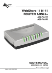
WebShare 142W
Wireless ADSL2+ Router
A02-RA142-W54
USER’S MANUAL
A02-RA142-W54 _ME01
Where solutions begin
Company certified ISO 9001:2000
Where solutions begin
Company certified ISO 9001:2000
WebShare 142W
INDICE
CHAPTER 1: INTRODUCTION
1.1 An Overview of WebShare Wireless ADSL2+ Router
1.2 Package Contents
1.3 WebShare Wireless Router ADSL2+ Features
1.4 WebShare Wireless Router ADSL2+ Application
1
1
2
2
4
CHAPTER 2: USING WEBSHARE WIRELESS ADSL2+ ROUTER
6
2.1 Cautions for using the WebShare Wireless ADSL2+ Router
2.2 The Front LEDs
2.3 The Rear Ports
2.4 Cabling
CHAPTER 3: CONFIGURATION
3.1 Before Configuration
3.1.1 Configuring PC for Windows 95/98/ME
3.1.2 Configuring PC for Windows NT4.0
3.1.3 Configuring PC for Windows 2000
3.1.4 Configuring PC for Windows XP
3.1.5 Configuring for MAC
3.1.6 Verification of Configuration
3.1.7 Browser Configuration
3.2 Factory Default Setting
3.2.1 Password
3.2.2 LAN and WAN Port Addresses
3.3 Reset of WebShare Wireless Router ADSL2+
3.4 Informations from the ISP
3.5 Browser Configuration
3.6 Surfing in Web GUI Configuration
3.7 Configuring Password
3.8 Resetting the ADSL Router
3.8.1 Using The Reset Button
6
6
7
8
9
9
10
12
13
15
17
18
18
19
19
20
20
20
21
21
22
23
23
WebShare 142W
CHAPTER 4: QUICK START
4.1 Wizard Setup Introduction
4.2 Encapsulation
4.2.1 PPP over Ethernet
4.2.2 PPPoA
4.2.3 RFC 1483
4.3 Multiplexing
4.3.1 VC-based Multiplexing
4.3.2 LLC-based Multiplexing
4.4 VPI and VCI
4.5 Quick Start
4.6 Wizard Setup Configuration: Connection Tests
CHAPTER 5: LAN SETUP
5.1 LAN Overview
5.1.1 LANs, WANs and the ADSL Router
5.2 DNS Server Address
5.3 DNS Server Address Assignment
5.4 LAN TCP/IP
5.4.1 Factory LAN Defaults
5.4.2 IP Address and Subnet Mask
5.4.3 RIP Setup
5.4.4 Multicast
5.5 Configuring LAN
5.6 Wireless
CHAPTER 6: WAN SETUP
6.1 WAN Overview
6.2 PPPoE Encapsulation
6.3 PPTP Encapsulation
6.4 Traffic Shaping
6.5 Configuring WAN Setup
CHAPTER 7: NETWORK ADDRESS TRANSLATION (NAT)
7.1 NAT Overview
7.1.1 NAT Definitions
7.1.2 What NAT Does
7.1.3 How NAT Works
7.1.4 NAT Application
24
24
24
24
24
24
25
25
25
25
25
28
29
29
29
29
30
30
30
31
31
31
33
35
40
40
40
40
40
42
47
47
47
47
48
48
WebShare 142W
7.1.5 NAT Mapping Types
7.2 SUA (Single User Account) Versus NAT
7.3 Virtual Server and DMZ
7.3.1 Port Forwarding: Services and Port Numbers
7.3.2 Virtual Server
Click on Advanced Setup then NAT.
7.4 Selecting the NAT Mode
49
50
50
50
52
52
54
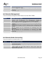
CHAPTER 8: ACCESS MANAGEMENT
57
8.1 ACL
8.2 IP Filter
8.3 SNMP
8.4 UPnP
8.5 DDNS
CHAPTER 9: ADVANCED SETUP
9.1 Routing
9.1.1 Add Route
9.2 NAT
9.2.2 DMZ
9.2.3 Virtual Server
9.2.4 IP Address Mapping
9.3 ADSL
CHAPTER 10: MAINTENANCE
10.1 Administration
10.2 Time Zone
10.3 Firmware
10.4 SysRestart
10.5 Diagnostic
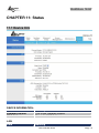
CHAPTER 11: STATUS
11.1 Device Info
11.2 System Log
11.3 Statistics
APPENDIX A: TROUBLESHOOTING
A.1 Using LEDs to Diagnose Problems
57
58
60
60
61
63
63
63
65
65
66
67
68
69
69
69
70
72
72
74
74
75
75
78
78
WebShare 142W
A.1.1 Power LED
A.1.2 LAN LED
A.1.3 DSL LED
A.2 Telnet
A.3 Web Configurator
A.4 Login Username and Password
A.5 LAN Interface
A.6 WAN Interface
A.7 Internet Access
A.8 Remote Management
A.9 Remote Node Connection
A.10 FAQ
78
78
78
79
79
80
80
81
81
82
82
83
APPENDIX B: TECHNICAL FEATURES
86
APPENDIX C:SUPPORT
87
WebShare 142W
A02-RA142-W54_ME01 (V1.0 October 2006)
WebShare 142W
Copyright Statement
No part of this publication may be reproduced, stored in a retrieval system, or
transmitted in any form or by any means, whether electronic, mechanical,
photocopying, recording or otherwise without the prior writing of the publisher.
Windows™ 98SE/2000/ME/XP are trademarks of Microsoft® Corp. Pentium is
trademark of Intel. All copyright reserved.
The Atlantis Land logo is a registered trademark of Atlantis Land SpA. All other
names mentioned mat be trademarks or registered trademarks of their respective
owners. Subject to change without notice. No liability for technical errors and/or
omissions.
Wireless LAN, Health and Authorization for use
Radio frequency electromagnetic energy is emitted from Wireless LAN devices.
The energy levels of these emissions however are far much less than the
electromagnetic energy emissions from wireless devices like for example mobile
phones. Wireless LAN devices are safe for use frequency safety standards and
recommendations. The use of Wireless LAN devices may be restricted in some
situations or environments for example:
·On board of airplanes, or
·In an explosive environment, or
·In case the interference risk to other devices or services is perceived or identified
as harmful
In case the policy regarding the use of Wireless LAN devices in specific
organizations or environments (e.g. airports, hospitals, chemical/oil/gas industrial
plants, private buildings etc.) is not clear, please ask for authorization to use
these devices prior to operating the equipment.
Regulatory Information/disclaimers
Installation and use of this Wireless LAN device must be in strict accordance with
the instructions included in the user documentation provided with the product. Any
changes or modifications made to this device that are not expressly approved by
the manufacturer may void the user’s authority to operate the equipment. The
Manufacturer is not responsible for any radio or television interference caused by
unauthorized modification of this device, of the substitution or attachment.
Manufacturer and its authorized resellers or distributors will assume no liability for
any damage or violation of government regulations arising from failing to comply
with these guidelines.
WebShare 142W
CE Mark Warning
This is a Class B product. In a domestic environment, this product may cause
radio interference, in which case the user may be required to take adequate
measures.
CE in which Countries where the product may be used freely:
Germany, UK, Italy, Spain, Belgium, Netherlands, Portugal, Greece, Ireland,
Denmark, Luxembourg, Austria, Finland, Sweden, Norway and Iceland.
France: except the channel 10 through 13, law prohibits the use of other
channels.
CE/EMC Restriction of Liability
The product described in this handbook was designed, produced and approved
according to the EMC-regulations and is certified to be within EMC limitations.
If the product is used in an uncertified PC, the manufacturer undertakes no
warranty in respect to the EMC limits. The described product in this handbook
was constructed, produced and certified so that the measured values are within
EMC limitations. In practice and under special circumstances, it may be possible,
that the product may be outside of the given limits if it is used in a PC that is not
produced under EMC certification. It is also possible in certain cases and under
special circumstances, which the given EMC peak values will become out of
tolerance. In these cases, the user himself is responsible for compliance with the
EMC limits.
Declaration of Conformity
This equipment has been tested and found to comply with Directive 1999/5/CE of
the European Parliament and of the Council on radio equipment and
telecommunications terminal equipment and the mutual recognition of their
conformity. After assessment, the equipment has been found to comply with the
following standards: EN 300.328 (radio), EN 301 489-1, EN 301 489-17
(electromagnetic compatibility) and EN 60950 (safety). This equipment may be
used in all European Union contries and in all countries applying Directive
1999/5/CE, without restriction, with the exception of the following countries:
France:When this equipment is used outdoors, output power is limited to within
the frequency bans listed on the chart. For more info, consult the website
www.art-telecom.fr.
Location
Frequency
Band Power (EIRP)
(MHz)
Indoor (no restriction) 2400-2483,5
100mW(20dBm)
Outdoor
2400-2454
100mW(20dBm)
2454-2483,5
10mW(10dBm)
Italy: For more info, consult the website www.comunicazioni.it
WebShare 142W
WebShare 142W
CHAPTER 1: Introduction
1.1 An Overview of WebShare Wireless ADSL2+ Router
Welcome to the WebShare Wireless ADSL2+ Router. Your WebShare Wireless
ADSL2+ Router is an “all-in-one” unit, combining an ADSL2+ modem, ADSL
router and Ethernet network switch, providing everything you need to get the
machines on your network connected to the Internet over your ADSL broadband
connection.
The WebShare Wireless ADSL2+ Router complies with ADSL2+ standards for
worldwide deployment and supports downstream rates of up to 24 Mbps and
upstream rates of up to 1 Mbps. It is designed for small office, home office and
residential users, enabling even faster speed Internet connections. User can
enjoy ADSL services and broadband multimedia applications such as interactive
gaming, video streaming and real-time audio much easier and faster than ever
before.
The product supports PPPoA (RFC 2364 – PPP (Point-to-Point Protocol) over
ATM Adaptation Layer 5), RFC 1483 encapsulation over ATM (bridged or routed),
PPP over Ethernet (RFC 2516), and IPoA (RFC1577) to establish a connection
with ISP. The product also supports VC-based and LLC-based multiplexing.
It is the perfect solution to connect a small group of PCs to a high-speed
broadband Internet connection. Multi-users can have high-speed Internet access
simultaneously.
This product also serves as an Internet firewall, protecting your network from
being accessed by outside users. Not only provide the natural firewall function
(Network Address Translation, NAT), it also provides rich firewall features to
secure user’s network. All incoming data packets are monitored and filtered.
Besides, it can also be configured to block internal users from accessing to the
Internet.
The product provides two levels of security support. First, it masks LAN users’ IP
addresses which are invisible to outside users on the Internet, making it much
more difficult for a hacker to target a machine on your network. Secondly, it can
block and redirect certain ports to limit the services that outside users can access.
For example, to ensure that games and other Internet applications will run
properly, user can open some specific ports for outside users to access internal
services in network.
Integrated DHCP (Dynamic Host Control Protocol) services, client and server,
allow multiple users to get their IP addresses automatically on boot up from the
product. Simply set local machines as a DHCP client to accept a dynamically
assigned IP address from DHCP server and reboot. Each time local machine is
powered up; the router will recognize it and assign an IP address to instantly
connect it to the LAN.
A02-RA142-W54
Pag. 1
WebShare 142W
For advanced users, Virtual Service function allows the product to provide limited
visibility to local machines with specific services for outside users. An ISP
(Internet Service Providers) provided IP address can be set to the product and
then specific services can be rerouted to specific computers on the local network.
For instance, a dedicated web server can be connected to the Internet via the
product and then incoming requests for HTML that are received by the product
can be rerouted to the dedicated local web server, even though the server now
has a different IP address. In this example, the product is on the Internet and
vulnerable to attacks, but the server is protected.
Virtual Server can also be used to re-task services to multiple servers. For
instance, the product can be set to allow separated FTP, Web, and Multiplayer
game servers to share the same Internet-visible IP address while still protecting
the servers and LAN users from hackers.
1.2 Package Contents
The package contains:
WebShare Wireless ADSL2+ Router
Vera (Multilanguage Interactive Tutorial)
CD-Rom containing the online manual
RJ-11 ADSL/telephone Cable
Ethernet (CAT-5 LAN) Cable
AC-DC power adapter
1.3 WebShare Wireless Router ADSL2+ Features
Technical charateristics of WebShare Wireless Router ADSL2+:
ADSL Multi-Mode Standard: supports downstream rates of up to 24 Mbps and
upstream rates of up to 1 Mbps. It also supports rate management that allows
ADSL subscribers to select an Internet access speed suiting their needs and
budgets. It is compliant with Multi-Mode standard (ANSI T1.413, Issue 2;
G.dmt(G.992.1); G.lite(G992.2)), G.hs (G994.1), G.dmt.bis (G.992.3),
G.dmt.bisplus (G.992.5)). The Annex A and B are supported in different H/W
platforms.
Multi-Protocol to Establish A Connection: Supports PPPoA (RFC 2364 - PPP
over ATM Adaptation Layer 5), RFC 1483 encapsulation over ATM (bridged or
routed), PPP over Ethernet (RFC 2516) and IPoA (RFC1577) to establish a
connection with the ISP. The product also supports VC-based and LLC-based
multiplexing.
Fast Ethernet Switch: A 10/100Mbps fast Ethernet switch is built in with
automatic switching between MDI and MDI-X for 10Base-T and 100Base-TX
A02-RA142-W54
Pag. 2
WebShare 142W
ports. An Ethernet straight or cross-over cable can be used directly for auto
detection.
Wireless Ethernet 802.11g: With built-in 802.11g access point for extending the
communication media to WLAN while providing the WEP and WPA for securing
your wireless networks.
Network Address Translation (NAT): Allows multi-users to access outside
resources such as the Internet simultaneously with one IP address/one Internet
access account. Many application layer gateway (ALG) are supported such as
web browser, ICQ, FTP, Telnet, E-mail, News, Net2phone, Ping, NetMeeting, IP
phone and others.
Frewall: Supports simple firewall with NAT technology and provides option for
blocking access from Internet, like Telnet, FTP, TFTP, WEB, SNMP and IGMP.
Domain Name System (DNS) relay: Provides an easy way to map the domain
name (a friendly name for users such as www.yahoo.com) and IP address. When
a local machine sets its DNS server with this router’s IP address, every DNS
conversion request packet from the PC to this router will be forwarded to the real
DNS in the outside network.
PPP over Ethernet (PPPoE): Provides embedded PPPoE client function to
establish a connection. Users can get greater access speed without changing the
operation concept, sharing the same ISP account and paying for one access
account. No PPPoE client software is required for local computer. The Automatic
Reconnect and Disconnect Timeout (Idle Timer) functions are provided, too.
Dynamic Host Control Protocol (DHCP) client and server: In the WAN site,
the DHCP client can get an IP address from the Internet Service Provider (ISP)
automatically. In the LAN site, the DHCP server can allocate a range of client IP
addresses and distribute them including IP address, subnet mask as well as DNS
IP address to local computers. It provides an easy way to manage the local IP
network.
RIP1/2 Routing: Supports RIP1/2 routing protocol for routing capability.
Web based GUI: Supports web based GUI for configuration and management. It
is user-friendly and comes with on-line help. It also supports remote management
capability for remote users to configure and manage this product.
Quick Installation Wizard: Supports a WEB GUI page to install this device
quickly. With this wizard, end users can enter the information easily which they
get from their ISP, then surf the Internet immediately.
Packet Filtering: Up to 72 rules.
A02-RA142-W54
Pag. 3
WebShare 142W
Universal Plug and Play (UPnP) e UPnP NAT Traversal: This protocol is used
to enable simple and robust connectivity among stand-alone devices and PCs
from many different vendors. It makes network simple and affordable for users.
UPnP architecture leverages TCP/IP and the Web to enable seamless proximity
networking in addition to control and data transfer among networked devices.
With this feature enabled, users can now connect to Net meeting or MSN
Messenger seamlessly.
Virtual Server: User can specify some services to be visible from outside users.
The router can detect incoming service request and forward it to the specific local
computer to handle it. For example, user can assign a PC in LAN acting as WEB
server inside and expose it to the outside network. Outside user can browse
inside web server directly while it is protected by NAT. A DMZ host setting is also
provided to a local computer exposed to the outside network, Internet.
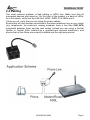
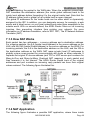
1.4 WebShare Wireless Router ADSL2+ Application
Follow the followings steps to cabling the device:
Connect WAN Port to the telephone line throught RJ-11 cable (contained in
package).
WebShare Wireless ADSL2+ Router can be connect in the following
configuration:
¾ Directly at 4 PC, throught CAT5 cables (one is contained in
package)
¾ To an Hub/Switch throught UPLINK Port thought CAT 5 cable
(contained in package).
Connect AC-DC Adapter on AC and on device (POWER jack) in the reat r of
the product.
A02-RA142-W54
Pag. 4
WebShare 142W
A02-RA142-W54
Pag. 5
WebShare 142W
CHAPTER 2: Using
ADSL2+ Router
WebShare
Wireless
2.1 Cautions for using the WebShare Wireless ADSL2+
Router
Do not place the Wireless Router ADSL2+ under high humidity and high
temperature.
Do not use the same power source for Wireless Router ADSL2+ with other
equipment.
Do not open or repair the case yourself.
If the Wireless Router ADSL2+ is too hot, turn off the power immediately and
have a qualified serviceman repair it.
Place the Wireless Router ADSL2+ on a stable surface.
Only use the power adapter that comes with the package.
Do NOT upgrade firmware on any Atlantis Land product over a wireless
connection.
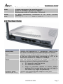
2.2 The Front LEDs
In the front of WebShare Wireless ADSL2+ Router, you can see a LED series
that show status of some functionality of product.
Following table contains meaning of front LEDs:
LED
Meaning
Lit when power is ON.
PWR
Lit when the system is ready.
SYS
Flashes green when the wireless connection is established.
WLAN
A02-RA142-W54
Pag. 6
WebShare 142W
LAN
ADSL
PPP
Flashes when sending/receiving data.
Lit when connected to an Ethernet device.
Green for 100Mbps; Orange for 10Mbps.
Blinking when data is Transmitted / Received.
Lit when successfully connected to an ADSL DSLAM
(“linesync”).
Lit steady when there is a PPPoA / PPPoE connection.
2.3 The Rear Ports
Ports
ADSL(Line)
LAN
Reset
POWER (jack)
POWER (Switch)
Meaning
Connect the supplied RJ-11 (“telephone”) cable to this
port when connecting to the ADSL/telephone network.
Connect a UTP Ethernet cable (Cat-5 or Cat-5e) to one
of the four LAN ports when connecting to a PC or an
office/home network of 10Mbps or 100Mbps.
After the device is powered on, press it to reset the
device or restore to factory default settings.
• 0-3 seconds: reset the device
• 3-5 seconds: no action
• Over 10 seconds: restore to factory default
settings (this is used when you can not login to
the router, e.g. forgot the password).
Connect the supplied power adapter to this jack.
A Power ON/OFF switch.
A02-RA142-W54
Pag. 7
WebShare 142W
2.4 Cabling
The most common problem is bad cabling or ADSL line. Make sure that all
connected devices are turned on. On the front of the product is a bank of LEDs.
As a first check, verify that the LAN Link, ADSL, PWR, SYS LEDs are lit.
If they are not, verify that you are using the proper cables.
Ensure that all other devices connected to the same telephone line as your router
(e.g. telephones, fax machines, analog modems) have a line filter (A01-AF2)
connected between them and the wall socket (unless you are using a Central
Splitter or Central Filter installed by a qualified and licensed electrician), and
ensure that all line filters are correctly installed and the right way around.
A02-RA142-W54
Pag. 8
WebShare 142W
CHAPTER 3: Configuration
WebShare Wireless Router ADSL2+ can be configured with your web browser. A
web browser is included as a standard application in the following operating
systems: Windows 98/NT/2000/XP/Me, MAC, Linux, etc. The product provides a
very easy and user-friendly interface for configuration.
3.1 Before Configuration
PCs must have an Ethernet interface installed properly and be connected to the
router either directly or through an external repeater hub, and have TCP/IP
installed and configured to obtain an IP address through a DHCP server or a fixed
IP address that must be in the same subnet as the router. The default IP address
of the router is 192.168.1.254 and the subnet mask is 255.255.255.0 (i.e. any
attached PC must be in the same subnet, and have an IP address in the range of
192.168.1.1 to 192.168.1.253). The best and easiest way is to configure the PC to
get an IP address automatically from the router using DHCP. If you encounter any
problems accessing the router’s web interface it may also be advisable to
uninstall any kind of software firewall on your PCs, as they can cause problems
accessing the 192.168.1.254 IP address of the router. Users should make their
own decisions on how to best protect their network.
Please follow the steps below for your PC’s network environment installation. First
of all, please check your PC’s network components. The TCP/IP protocol stack
and Ethernet network adapter must be installed. If not, please refer to your
Windows-related or other operating system manuals.
Any TCP/IP capable workstation can be used to communicate
with or through the WebShare Wireless ADSL2+ Router. To
configure other types of workstations, please consult the
manufacturer’s documentation.
A02-RA142-W54
Pag. 9
WebShare 142W
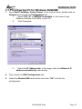
3.1.1 Configuring PC for Windows 95/98/ME
1. Go to Start / Settings / Control Panel. In the Control Panel, double-click on
Network and choose the Configuration tab.
1.
Select TCP / IP -> NE2000 Compatible, or the name of any
Network Interface Card (NIC) in your PC.
2.
Click Properties.
3.
Select the IP Address tab. In this page, click the Obtain an IP
address automatically radio button.
2. Then select the DNS Configuration tab.
3. Select the Disable DNS radio button and click “OK” to finish the
configuration.
A02-RA142-W54
Pag. 10
WebShare 142W
A02-RA142-W54
Pag. 11
WebShare 142W
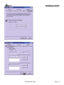
3.1.2 Configuring PC for Windows NT4.0
1. Go to Start / Settings / Control Panel. In the Control Panel, double-click on
Network and choose the Protocols tab.
2. Select TCP/IP Protocol and click
Properties.
3. Select the Obtain an IP address
from a DHCP server radio button
and click “OK”.
A02-RA142-W54
Pag. 12
WebShare 142W
3.1.3 Configuring PC for Windows 2000
1. Go to Start / Settings / Control Panel. In the Control Panel, double-click on
Network and Dial-up Connections.
2. Double-click LAN Area Connection.
3. In the LAN Area Connection Status window, click Properties.
A02-RA142-W54
Pag. 13
WebShare 142W
4. Select Internet Protocol (TCP/IP) and click Properties
5. Select the Obtain an IP address automatically and the Obtain DNS server
address automatically radio buttons.
6. Click “OK” to finish the configuration.
A02-RA142-W54
Pag. 14
WebShare 142W
3.1.4 Configuring PC for Windows XP
1. Go to Start / Control Panel (in Classic View). In the Control Panel, doubleclick on Network Connections.
2. Double-click Local Area Connection
A02-RA142-W54
Pag. 15
WebShare 142W
3. In the LAN Area Connection Status window, click Properties.
4. Select Internet Protocol (TCP/IP) and click Properties.
5. Select the Obtain an IP address automatically and the Obtain DNS server
address automatically radio buttons.
6. Click “OK” to finish the configuration.
A02-RA142-W54
Pag. 16
WebShare 142W
3.1.5 Configuring for MAC
1. Click on Apple Menu and
select
Control
Panel/TCP/IP. It will appear
the follow screen.
2. Select Ethernet on Connect
Via.
3. Select Using DHCP Server
on Configure.
4. Leave empty the field DHCP
Client ID.
A02-RA142-W54
Pag. 17
WebShare 142W
3.1.6 Verification of Configuration
To verify your correct configuration (after PC restart, necessary for Windows 98,
98Se, ME and instead enough obtain IP lease for XP, 2000),use ping command.
From a DOS Window, type:
ping 192.168.1.254.
If It show you this message:
Pinging 192.168.1.254 with 32 bytes of data:
Reply from 192.168.1.254: bytes=32 times<10ms TTL=64
Reply from 192.168.1.254: bytes=32 times<10ms TTL=64
Reply from 192.168.1.254: bytes=32 times<10ms TTL=64
It i s possibile to continue to follow step. If it show you follow message:
Pinging 192.168.1.254 with 32 bytes of data:
Request timed out.
Request timed out.
Request timed out.
Check that LAN LED is lit (change CAT cable if is not). Check PC IP Address
typing winipcfg for (Win95,98,ME) or ipconfig (for Win2000,XP) and eventually
re-install TCP/IP stack.
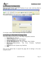
3.1.7 Browser Configuration
Now open IE, go to Instruments menu, select the Connections tab and select
one of the following options:
•
•
Never use remote connection
Use remote connection if another network connection isn’t available
A02-RA142-W54
Pag. 18
WebShare 142W
3.2 Factory Default Setting
Before configuring your, you need to know the following default settings:
Username: admin
Password: atlantis
IP Address (192.168.1.254)
Subnet Mask (255.255.255.0)
ISP Setting in WAN Side = PPPoA, VCMux, Routing, VPI=8, VCI=35
DHCP Server enabled with IP pool from192.168.1.100 to 192.168.1.199
Wireless: SSSID= A02-RA142-W54, Channel=6, WEP=disable
3.2.1 Password
The default username and password are admin and atlantis respectively.
If you ever forget the password to log in, you may press the RESET
button up to 6 seconds to restore the factory default settings.
A02-RA142-W54
Pag. 19
WebShare 142W
3.2.2 LAN and WAN Port Addresses
The parameters of LAN and WAN ports are pre-set in the factory. The default
values are shown below.
Porta LAN
Porta WAN
192.168.1.254
IP address
Mode=Routing
Encapsulation=PPPoA
255.255.255.0
Subnet Mask
Multiplex=VC
Enabled
DHCP server function
VPI=8
100 IP addresses
IP addresses for
VCI=35
continuing from
distribution to PCs
192.168.1.100 through
192.168.1.199
3.3 Reset of WebShare Wireless Router ADSL2+
If you forget the password, you can restore router with Default Factory Setting
using “Reset” button in the rear of the product. To do this operation is necessary
be sure that led SYS is lit, then press “Reset” button for 10 seconds. The LED
SYS will turn off and it will blink; it will be lit when firmware with Factory Default
Setting will be loaded. Now you can enter on WebShare Wireless Router ADSL2+
with password “atlantis”.
3.4 Informations from the ISP
Before configuring this device, you have to check with your ISP (Internet Service
Provider) what kind of service is provided such as PPPoE, PPPoA, RFC1483, or
IPoA.
Gather the information as illustrated in the following table and keep it for
reference.
VPI/VCI, VC-based/LLC-based multiplexing, Username,
Password, Service Name, and Domain Name System (DNS)
PPPoE
IP address (it can be automatically assigned by your ISP when
you connect or be set manually).
VPI/VCI, VC-based/LLC-based multiplexing, Username,
Password, and Domain Name System (DNS) IP address (it
PPPoA
can be automatically assigned by your ISP when you connect
or be set manually).
VPI/VCI, VC-based/LLC-based multiplexing to use Bridged
RFC1483
Mode.
Bridged
VPI/VCI, VC-based/LLC-based multiplexing, IP address,
RFC1483
Subnet mask, Gateway address, and Domain Name System
Routed
(DNS) IP address (it is fixed IP address).
A02-RA142-W54
Pag. 20
WebShare 142W
3.5 Browser Configuration
Open your web browser, enter the IP address of your router, which by default is
192.168.1.254, and click “Go”.
The default username and password are “admin” and “atlantis”.
You will get a status report web page when login successfully.
3.6 Surfing in Web GUI Configuration
This section descrive how to surf on Site Map configuration Interface.
• Quick Start (Run Wizard)
• Interface Setup(Internet, LAN, Wireless)
• Advanced Setup(Routing, NAT, ADSL)
• Access Management(ACL, IP Filter, SNMP, UPnP, DDNS)
• Maintenance(Administration, Time Zone, Firmware, SysRestart,
Diagnostics)
• Status(Device Info, System Log, Statistics)
• Help
Click on the desired item to expand the page with all settings in the main
navigation panel.
A02-RA142-W54
Pag. 21
WebShare 142W
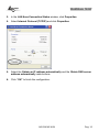
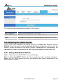
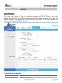
3.7 Configuring Password
It is highly recommended that you change the password for accessing the ADSL
Router. To change the ADSL Router’ password, click Maintenance and then
Administration . The screen appears as shown.
A02-RA142-W54
Pag. 22
WebShare 142W
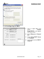
The following table describes the labels in this screen.
Label
New Password
Confirm Password
Save
Cancel
Description
Type the new password in this field.
Type the new password again in this field.
Click Apply to save your changes back to the ADSL Router.
Click Cancel to begin configuring this screen afresh.
3.8 Resetting the ADSL Router
If you forget your password or cannot access the WebShare Wireless Router
ADSL2+, you will need to reload the factory-default configuration file or use the
RESET button the back of the ADSL Router. Uploading this configuration file
replaces the current configuration file with the factory-default configuration file.
3.8.1 Using The Reset Button
Step 1. Make sure the SYS LED is on (not blinking).
Step 2. Press the RESET button for 10 (or more) seconds, and then release it.
When the SYS LED begins to blink, the defaults have been restored and the
ADSL Router restarts.
A02-RA142-W54
Pag. 23
WebShare 142W
CHAPTER 4: Quick Start
This chapter provides information on the Wizard Setup screens in the web
configurator.
4.1 Wizard Setup Introduction
Use the Wizard Setup screens to configure your system for Internet access
settings and fill in the fields with the information in the Internet Account
Information table of the Compact Guide or Read Me First. Your ISP may have
already configured some of the fields in the wizard screens for you.
4.2 Encapsulation
Be sure to use the encapsulation method required by your ISP. The ADSL Router
supports the following methods.
4.2.1 PPP over Ethernet
PPPoE provides access control and billing functionality in a manner similar to
dial-up services using PPP. The ADSL Router bridges a PPP session over
Ethernet (PPP over Ethernet, RFC 2516) from your computer to an ATM PVC
(Permanent Virtual Circuit) which connects to ADSL Access Concentrator where
the PPP session terminates. One PVC can support any number of PPP sessions
from your LAN. For more information on PPPoE, see the appendix.
4.2.2 PPPoA
PPPoA stands for Point to Point Protocol over ATM Adaptation Layer 5 (AAL5). It
provides access control and billing functionality in a manner similar to dial-up
services using PPP. The ADSL Router encapsulates the PPP session based on
RFC1483 and sends it through an ATM PVC (Permanent Virtual Circuit) to the
Internet Service Provider's (ISP) DSLAM (digital access multiplexer). Please refer
to RFC 2364 for more information on PPPoA. Refer to RFC 1661 for more
information on PPP.
4.2.3 RFC 1483
RFC 1483 describes two methods for Multiprotocol Encapsulation over ATM
Adaptation Layer 5 (AAL5). The first method allows multiplexing of multiple
protocols over a single ATM virtual circuit (LLC-based multiplexing) and the
second method assumes that each protocol is carried over a separate ATM virtual
circuit (VC-based multiplexing). Please refer to the RFC for more detailed
information.
A02-RA142-W54
Pag. 24
WebShare 142W
4.3 Multiplexing
There are two conventions to identify what protocols the virtual circuit (VC) is
carrying. Be sure to use the multiplexing method required by your ISP.
4.3.1 VC-based Multiplexing
In this case, by prior mutual agreement, each protocol is assigned to a specific
virtual circuit; for example, VC1 carries IP, etc. VC-based multiplexing may be
dominant in environments where dynamic creation of large numbers of ATM VCs
is fast and economical.
4.3.2 LLC-based Multiplexing
In this case one VC carries multiple protocols with protocol identifying information
being contained in each packet header. Despite the extra bandwidth and
processing overhead, this method may be advantageous if it is not practical to
have a separate VC for each carried protocol, for example, if charging heavily
depends on the number of simultaneous VCs.
4.4 VPI and VCI
Be sure to use the correct Virtual Path Identifier (VPI) and Virtual Channel
Identifier (VCI) numbers assigned to you. The valid range for the VPI is 0 to 255
and for the VCI is 32 to 65535 (0 to 31 is reserved for local management of ATM
traffic). Please see the appendix for more information.
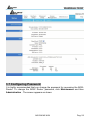
4.5 Quick Start
Following next steps you can make operating WebShare Wireless Router
ADSL2+ in short time using PCs in DHCP mode. Refer to manual on Installation
CD if you need personalized configuration.
Click on Quick Start then Run Wizard to perform an automatic protocol
selection.
The following screen will appear. Please click Next to continue.
A02-RA142-W54
Pag. 25
WebShare 142W
You can change the password as you like and then click Next to continue.
Select your time zone from the drop down list. Please click Next to continue.
Select how the router will set up the Internet connection: PPPoE/PPPoA: to
obtain IP automatically (You need username and password).
Static IP address: this configuration is valid in case of a subscription with a
static IP.
PPPoE/PPPoA
PPPoE (PPP over Ethernet) is an ADSL connection known as dial-up DSL. As
the PPPoA it has been created to integrate large band services paying a
particular attention to an easy configuration. The user can obtain an high access
speed and he can also share the same account with the ISP. No additional
software are required. This configuration is valid in case of a subscription with a
A02-RA142-W54
Pag. 26
WebShare 142W
static IP and active NAT (SUA) (for the managing of the public class turn to the
CD handbook). Let’s see how to configure correctly this kind of ADSL
configuration.
Insert Username and Password and make sure that the parameters are, in case
of PPPoA, the ones in the picture, if not specifically shown by the ISP.
In case of PPPoE choose Connection Type=PPPoE LLC.
Click on Next.
You have to pay particular attention to the WAN-ADSL
connection. If you have any doubt turn to qualified personnel or
contact Atlantis-Land technical assistance. Atlantis Land will not
be considered
responsible in case of
wrong or bad
configuration.
STATIC IP ADDRESS
This configuration is valid in case of a subscription with a static IP and active NAT
SUA (for the managing of the public class turn to the CD Manual). Make sure that
the parameters are, in case of RFC1483, the ones in the picture, if not
specifically shown by the ISP.
Insert then the public static IP address given by the ISP and choose Connection
Type=1483 Routed IP LLC(IPoA). Make sure that the parameters are, the ones
in the picture, if not specifically shown by the ISP.
A02-RA142-W54
Pag. 27
WebShare 142W
Click on Next.
4.6 Wizard Setup Configuration: Connection Tests
Launch your web browser and navigate to www.atlantis-land.com Internet access
is just the beginning. Refer to the rest of this User’s Guide for more detailed
information on the complete range of ADSL Router features. If you cannot access
the Internet, open the web configurator again to confirm that the Internet settings
you configured in the Wizard Setup are correct.
The Webshare Wireless Router ADSL2+ automatically tests the connection to the
computer(s) connected to the LAN ports. To test the connection from the ADSL
Router to the ISP, click Maintenance then Diagnose.
A02-RA142-W54
Pag. 28
WebShare 142W
CHAPTER 5: LAN Setup
This chapter describes how to configure LAN settings.
5.1 LAN Overview
A Local Area Network (LAN) is a shared communication system to which many
computers are attached. A LAN is a computer network limited to the immediate
area, usually the same building or floor of a building.
The LAN screens can help you configure a LAN DHCP server and manage IP
addresses.
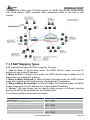
5.1.1 LANs, WANs and the ADSL Router
The actual physical connection determines whether the ADSL Router ports are
LAN or WAN ports. There are two separate IP networks, one inside, the LAN
network; the other outside: the WAN network as shown next:
5.2 DNS Server Address
DNS (Domain Name System) is for mapping a domain name to its corresponding
IP address and vice versa, for example, the IP address of www.atlantis-land.com
is 204.217.0.2. The DNS server is extremely important because without it, you
must know the IP address of a machine before you can access it. The DNS
A02-RA142-W54
Pag. 29
WebShare 142W
server addresses that you enter in the DHCP setup are passed to the client
machines along with the assigned IP address and subnet mask.
There are two ways that an ISP disseminates the DNS server addresses. The first
is for an ISP to tell a customer the DNS server addresses, usually in the form of
an information sheet, when s/he signs up. If your ISP gives you the DNS server
addresses, enter them in the DNS Server fields in DHCP Setup, otherwise, leave
them blank.
Some ISP’s choose to pass the DNS servers using the DNS server extensions of
PPP IPCP (IP Control Protocol) after the connection is up. If your ISP did not give
you explicit DNS servers, chances are the DNS servers are conveyed through
IPCP negotiation. The ADSL Router supports the IPCP DNS server extensions
through the DNS proxy feature.
If the Primary and Secondary DNS Server fields in DHCP Setup are not specified,
for instance, left as 0.0.0.0, the ADSL Router tells the DHCP clients that it itself is
the DNS server. When a computer sends a DNS query to the ADSL Router, the
ADSL Router forwards the query to the real DNS server learned through IPCP
and relays the response back to the computer.
Please note that DNS proxy works only when the ISP uses the IPCP DNS server
extensions. It does not mean you can leave the DNS servers out of the DHCP
setup under all circumstances. If your ISP gives you explicit DNS servers, make
sure that you enter their IP addresses in the DHCP Setup menu. This way, the
ADSL Router can pass the DNS servers to the computers and the computers can
query the DNS server directly without the ADSL Router’s intervention.
5.3 DNS Server Address Assignment
Use DNS (Domain Name System) to map a domain name to its corresponding IP
address and vice versa. The DNS server is extremely important because without
it, you must know the IP address of a computer before you can access it.
There are two ways that an ISP disseminates the DNS server addresses.
1. The ISP tells you the DNS server addresses, usually in the form of an
information sheet, when you sign up. If your ISP gives you DNS server
addresses, enter them in the DNS Server fields in DHCP Setup.
2. Leave the DNS Server fields in DHCP Setup blank (for example 0.0.0.0). The
ADSL Router acts as a DNS proxy when this field is blank.
5.4 LAN TCP/IP
The ADSL Router has built-in DHCP server capability that assigns IP addresses
and DNS servers to systems that support DHCP client capability.
5.4.1 Factory LAN Defaults
The LAN parameters of the ADSL Router are preset in the factory with the
following values:
IP address of 192.168.1.254 with subnet mask of 255.255.255.0 (24 bits)
A02-RA142-W54
Pag. 30
WebShare 142W
DHCP server enabled with 100 client IP addresses starting from 192.168.1.100.
These parameters should work for the majority of installations. If your ISP gives
you explicit DNS server address(es), read the embedded web configurator help
regarding what fields need to be configured.
5.4.2 IP Address and Subnet Mask
Refer to the IP Address and Subnet Mask section in the Wizard Setup chapter for
this information.
5.4.3 RIP Setup
RIP (Routing Information Protocol) allows a router to exchange routing
information with other routers. The RIP Direction field controls the sending and
receiving of RIP packets. When set to:
1. Both - the ADSL Router will broadcast its routing table periodically and
incorporate the RIP information that it receives.
2. In Only - the ADSL Router will not send any RIP packets but will accept all RIP
packets received.
3. Out Only - the ADSL Router will send out RIP packets but will not accept any
RIP packets received.
4. None - the ADSL Router will not send any RIP packets and will ignore any RIP
packets received.
The Dynamic Route field controls the format and the broadcasting method of the
RIP packets that the ADSL Router sends (it recognizes both formats when
receiving). RIP-1 is universally supported; but RIP-2 carries more information.
RIP-1 is probably adequate for most networks, unless you have an unusual
network topology.
Both RIP-2B and RIP-2M sends the routing data in RIP-2 format; the difference
being that RIP-2B uses subnet broadcasting while RIP-2M uses multicasting.
5.4.4 Multicast
Traditionally, IP packets are transmitted in one of either two ways - Unicast (1
sender - 1 recipient) or Broadcast (1 sender - everybody on the network).
Multicast delivers IP packets to a group of hosts on the network - not everybody
and not just 1.
IGMP (Internet Group Multicast Protocol) is a network-layer protocol used to
establish membership in a Multicast group - it is not used to carry user data.
IGMP version 2 (RFC 2236) is an improvement over version 1 (RFC 1112) but
IGMP version 1 is still in wide use. If you would like to read more detailed
information about interoperability between IGMP version 2 and version 1, please
see sections 4 and 5 of RFC 2236. The class D IP address is used to identify host
groups and can be in the range 224.0.0.0 to 239.255.255.255. The address
A02-RA142-W54
Pag. 31
WebShare 142W
224.0.0.0 is not assigned to any group and is used by IP multicast computers.
The address 224.0.0.1 is used for query messages and is assigned to the
permanent group of all IP hosts (including gateways). All hosts must join the
224.0.0.1 group in order to participate in IGMP. The address 224.0.0.2 is
assigned to the multicast routers group.
The ADSL Router supports both IGMP version 1 (IGMP-v1) and IGMP version 2
(IGMP-v2). At start up, the ADSL Router queries all directly connected networks
to gather group membership. After that, the ADSL Router periodically updates this
information. IP multicasting can be enabled/disabled on the ADSL Router LAN
and/or WAN interfaces in the web configurator (LAN; WAN). Select None to
disable IP multicasting on these interfaces.
A02-RA142-W54
Pag. 32
WebShare 142W
5.5 Configuring LAN
Click “Interface Setup” then “LAN” to open the following screen.
The following table describes the labels in this screen.
Router Local IP
Enter the IP address of the ADSL Router in dotted decimal
IP Address
notation, for example, 192.168.1.254 (factory default).
IP Subnet Mask Type the subnet mask assigned to you by your ISP (if given).
Select the RIP direction from None, Both, In Only and Out
RIP Direction
Only.
Select the RIP version from RIP-1, RIP-2B and RIP-2M.
RIP Version
IGMP (Internet Group Multicast Protocol) is a session-layer
Multicast
protocol used to establish membership in a multicast group.
The ADSL Router supports both IGMP version 1 (IGMP-v1)
and IGMP-v2. Select None to disable it.
Click this button to save these settings back to the ADSL
Save
Router.
Click this button to reset the fields in this screen.
Cancel
A02-RA142-W54
Pag. 33
WebShare 142W
DHCP
Label
DHCP
Description
If set to Enabled, the ADSL Router can assign IP addresses,
an IP default gateway and DNS servers to Windows 95,
Windows NT and other systems that support the DHCP client.
If set to Disabled, the DHCP server will be disabled.
If set to Relay, the ADSL Router acts as a surrogate DHCP
server and relays DHCP requests and responses between the
remote server and the clients. Enter the IP address of the
actual, remote DHCP server in the Remote DHCP Server field
in this case.
When DHCP is used, the following items need to be set:
This field specifies the first of the contiguous addresses in the
Starting IP
IP address pool.
Address
This field specifies the size or count of the IP address pool.
IP Pool count
This field specifies the length of time for the IP lease.
Lease Time
If user want to disable this feature, he just need to set both
DNS Relay
Primary and secondary DNS IP to 0.0.0.0. Using DNS relay,
users can setup DNS server IP to 192.168.1.1 on their
Computer. If not, device will perform as no DNS relay.
Enter the IP addresses of the DNS servers. The DNS servers
Primary DNS
are passed to the
Server
DHCP clients along with the IP address and the subnet mask.
Secondary DNS As above.
Server
Click this button to save these settings back to the ADSL
Save
Router.
Click this button to reset the fields in this screen.
Cancel
A02-RA142-W54
Pag. 34
WebShare 142W
5.6 Wireless
This section introduces the wireless LAN and some basic configurations. Wireless
LANs can be as simple as two computers with wireless LAN cards communicating
in a peer-to-peer network or as complex as a number of computers with wireless
LAN cards communicating through access points which bridge network traffic to
the wired LAN.
Click on “Interface Setup” then “Wireless”.
Wireless LAN
Label
Access Point
SSSID
Description
Default setting is set to Activated. If you do not have any
wireless, both 802.11g and 802.11b, device in your network,
select Deactived.
The SSID is the unique name of a wireless access point (AP)
to be distinguished
from another. For security propose, change the default A02RA142-W54 to a unique ID name to the AP which is already
built-in to the router’s wireless interface. It is case sensitive
and must not excess 32 characters. Make sure your wireless
clients have exactly the SSID as the
A02-RA142-W54
Pag. 35
WebShare 142W
device, in order to get connected to your network.
Broacast SSSID Select Yes to hide the SSID in so a station cannot obtain the
SSID through passive scanning. Select No to make the SSID
visible so a station can obtain the SSID through passive
scanning.
The range of radio frequencies used by IEEE 802.11b/g
Channel ID
wireless devices is called a channel. Select a channel from
the drop-down list box.
Authentication To prevent unauthorized wireless stations from accessing
data transmitted over the network, the router offers highly
Type
secure data encryption, known as WEP.&WPA. If you require
high security for transmissions, there are two alternatives to
select from: 64-bit WEP and 128-bit WEP. WEP 128 will offer
increased security over WEP 64.
You can disable or enable with WPA or WEP for protecting
wireless network. The default type of wireless is disabled and
to allow all wireless computers to communicate with the
access points without any data encryption.
The range of radio frequencies used by IEEE 802.11g wireless
devices is called a “channel”. Channels available depend on your
geographical area. You may have a choice of channels (for your
region) so you should use a different channel than an adjacent AP
(access point) to reduce interference. Interference occurs when
radio signals from different access points overlap causing
interference and degrading performance.
Adjacent channels partially overlap however. To avoid interference
due to overlap, your AP should be on a channel at least five
channels away from a channel that an adjacent AP is using. For
example, if your region has 11 channels and an adjacent AP is using
channel 1, then you need to select a channel between 6 or 11.
Authentication Type
Label
Description
To disable the WPA/WEP security.
Disabled
WEP-64bits or Enter the key to encrypt wireless data. To allow encrypted data
WEP-128bits transmission, the WEP Encryption Key values on all wireless
stations must be the same as
the router. There are four keys for your selection. The input
format is in HEX style, 5 and 13 HEX codes are required for 64bitWEP and 128-bitWEP respectively.
If you chose WEP 64-bits, then enter any 5 ASCII characters or
10 hexadecimal characters ("0-9", "A-F").
If you chose WEP 128-bits, then enter 13 ASCII characters or
26 hexadecimal characters ("0-9", "A-F").
A02-RA142-W54
Pag. 36
WebShare 142W
You must configure all four keys, but only one key can be
activated at any one time. The default key is key 1.
WPA-PSK
Wi-Fi Protected Access (WPA) is the newest and best available
standard in Wi-Fi security. Two modes are available: PreShared Key and RADIUS. Pre-Shared Key gives you a choice of
two encryption methods: TKIP (Temporal Key Integrity Protocol),
which utilizes a stronger encryption method and incorporates
Message Integrity Code (MIC) to provide protection against
hackers, and AES (Advanced Encryption System), which utilizes
a symmetric 128-Bit block data encryption.
Encryption: TKIP (Temporal Key Integrity Protocol) utilizes a
stronger encryption method and incorporates Message Integrity
Code (MIC) to provide protection against
hackers.
Pre-Shared key: The key for network authentication. The input
format is in character style and key size should be in the range
between 8 and 64 characters.
A02-RA142-W54
Pag. 37
WebShare 142W
Advanced Setting
Description
Label
Beacon Interval The Beacon Interval value indicates the frequency interval of
the beacon. Enter a value between 20 and 1000. A beacon is
a packet broadcast by the Router to synchronize the wireless
network.
The RTS (Request To Send) threshold (number of bytes) for
RTS/CTS
enabling RTS/CTS handshake. Data with its frame size larger
Threshold
than this value will perform the RTS/CTS handshake. Setting
this attribute to be larger than the maximum MSDU (MAC
service data unit) size turns off the RTS/CTS handshake.
Setting this attribute to zero turns on the RTS/CTS handshake
Enter a value between 1500 and 2347.
Fragmentation The threshold (number of bytes) for the fragmentation
boundary for directed messages. It is the maximum data
Threshold
fragment size that can be sent.
Enter a value between 256 and 2346.
This value, between 1 and 255, indicates the interval of the
DTIM
Delivery Traffic Indication Message (DTIM).
The default setting is 802.11b+g (Mixed mode). If you do not
802.11 b/g
know or have both 11g and 11b devices in your network, then
keep the default in mixed mode. From the drop-down manual,
you can select 802.11g if you have only 11g card. If you have
only 11b card, then select 802.11b.
A02-RA142-W54
Pag. 38
WebShare 142W
Wireless MAC Address Filter
The MAC filter screen allows you to configure the router to give exclusive access
to up to 32 devices (Allow Association) or exclude up to 32 devices from
accessing the router (Deny Association). Every Ethernet device has a unique
MAC (Media Access Control) address.
The MAC address is assigned at the factory and consists of six pairs of
hexadecimal characters, for example, 00:AA:BB:00:00:02. You need to know the
MAC address of the devices to configure this screen.
To change your router’s MAC filter settings, click Wireless LAN, MAC Filter to
open the MAC Filter screen. The screen appears as shown.
Label
Description
Activated/Deactivated Select Actived to enable MAC address filtering.
Define the filter action for the list of MAC addresses in
Action
the MAC address filter table.
Select Deny Association to block access to the router,
MAC addresses not listed will be allowed to access the
router.
Select Allow Association to permit access to the router,
MAC addresses not listed will be denied access to the
router.
Enter the MAC addresses (in XX:XX:XX:XX:XX:XX
MAC Address
format) of the wireless station that are allowed or denied
access to the router in these address fields.
A02-RA142-W54
Pag. 39
WebShare 142W
CHAPTER 6: WAN Setup
This chapter describes how to configure WAN settings.
6.1 WAN Overview
A WAN (Wide Area Network) is an outside connection to another network or the
Internet.
See the Wizard Setup chapter for more information on the fields in the WAN
screens.
6.2 PPPoE Encapsulation
The ADSL Router supports PPPoE (Point-to-Point Protocol over Ethernet).
PPPoE is an IETF Draft standard (RFC 2516) specifying how a personal
computer (PC) interacts with a broadband modem (DSL, cable, wireless, etc.)
connection. The PPPoE option is for a dial-up connection using PPPoE.
For the service provider, PPPoE offers an access and authentication method that
works with existing access control systems (for example Radius). PPPoE
provides a login and authentication method that the existing Microsoft Dial-Up
Networking software can activate, and therefore requires no new learning or
procedures for Windows users.
One of the benefits of PPPoE is the ability to let you access one of multiple
network services, a function known as dynamic service selection. This enables
the service provider to easily create and offer new IP services for individuals.
Operationally, PPPoE saves significant effort for both you and the ISP or carrier,
as it requires no specific configuration of the broadband modem at the customer
site.
By implementing PPPoE directly on the ADSL Router (rather than individual
computers), the computers on the LAN do not need PPPoE software installed,
since the ADSL Router does that part of the task. Furthermore, with NAT, all of the
LANs’ computers will have access.
6.3 PPTP Encapsulation
Point-to-Point Tunneling Protocol (PPTP) is a network protocol that enables
secure transfer of data from a remote client to a private server, creating a Virtual
Private Network (VPN) using TCP/IP-based networks.
PPTP supports on-demand, multi-protocol and virtual private networking over
public networks, such as the Internet.
6.4 Traffic Shaping
Traffic Shaping is an agreement between the carrier and the subscriber to
regulate the average rate and “burstiness” or fluctuation of data transmission over
A02-RA142-W54
Pag. 40
WebShare 142W
an ATM network. This agreement helps eliminate congestion, which is important
for transmission of real time data such as audio and video connections.
Peak Cell Rate (PCR) is the maximum rate at which the sender can send cells.
This parameter may be lower (but not higher) than the maximum line speed. 1
ATM cell is 53 bytes (424 bits), so a maximum speed of 832 Kbps gives a
maximum PCR of 1962 cells/sec. This rate is not guaranteed because it is
dependent on the line speed.
Sustained Cell Rate (SCR) is the mean cell rate of a bursty, on-off traffic source
that can be sent at the peak rate, and a parameter for burst-type traffic. SCR may
not be greater than the PCR; the system default is 0 cells/sec.
Maximum Burst Size (MBS) is the maximum number of cells that can be sent at
the PCR. After MBS is reached, cell rates fall below SCR until cell rate averages
to the SCR again. At this time, more cells (up to the MBS) can be sent at the PCR
again.The following figure illustrates the relationship between PCR, SCR and
MBS.
A02-RA142-W54
Pag. 41
WebShare 142W
6.5 Configuring WAN Setup
To change the ADSL Router’s WAN remote node settings, click Interface Setup
then Internet. The screen differs by the encapsulation.
A02-RA142-W54
Pag. 42
WebShare 142W
The following table describes the labels in this screen.
PARAMETRES
DESCRIPTION
ATM VC
VPI (Virtual Path Identifier) and VCI (Virtual Channel Identifier)
Virtual Circuit ID
define a virtual circuit.
Activated or Deactivated
Status
The valid range for the VPI is 0 to 255. Enter the VPI assigned
VPI
to you. This field may already be configured.
The valid range for the VCI is 32 to 65535. Enter the VCI
VCI
assigned to you. This field may already be configured.
Select CBR (Continuous Bit Rate) to specify fixed (always-on)
bandwidth for voice or data traffic. Select UBR (Unspecified Bit
Rate) for applications that are non-time sensitive, such as eATM QoS Type
mail. Select VBR (Variable Bit Rate) for bursty traffic and
bandwidth sharing with other applications.
VBR is not available on all models.
Cell rate configuration often helps eliminate traffic congestion
that slows transmission of real time data such as audio and
Cell Rate
video connections.
Divide the DSL line rate (bps) by 424 (the size of an ATM cell) to
Peak Cell Rate find the Peak Cell Rate (PCR). This is the maximum rate at
which the sender can send cells. Type the PCR here.
The Sustain Cell Rate (SCR) sets the average cell rate (longSustain Cell
term) that can be transmitted. Type the SCR, which must be
Rate
less than the PCR.
Maximum Burst Size (MBS) refers to the maximum number of
Maximum Burst
cells that can be sent at the peak rate. Type the MBS, which is
Size
less than 65535.
ENCAPSULATION
Select the method of encapsulation used by your ISP from the
Encapsulation
drop-down list box.
PPPoA/PPPoE
Service Name
User Name
Password
(PPPoE only) Type the name of your PPPoE service here.
Enter the user name exactly as your ISP assigned. If assigned a
name in the form user@domain where domain identifies a
service name, then enter both components exactly as given.
A static IP address is a fixed IP that your ISP gives you. A
dynamic IP address is not fixed; the ISP assigns you a different
one each time you connect to the Internet. The Single User
Account feature can be used with either a dynamic or static IP
address.
A02-RA142-W54
Pag. 43
WebShare 142W
Multiplex
Select Obtain an IP Address Automatically if you have a
dynamic IP address; otherwise select Static IP Address and
type your ISP assigned IP address in the IP Address field below.
Select the method of multiplexing used by your ISP from the
drop-down list. Choices are VC or LLC.
Connection Settings
Select Always ON Connection when you want your connection
Always ON
up all the time. The ADSL Router will try to bring up the
connection automatically if it is disconnected.
Connect on demand is dependent on the traffic. If there is no
traffic (or Idle) for a pre-specified period of time), the connenct
Connect on
will tear down automatically. And once there is traffic send or
Demand
receive, the connection will be automatically on. Please insert
the Idle Time in minute.
IP Address
The IP address can be either dynamically (via DHCP) or given
Get IP Address IP address provide by your ISP. For Static IP, you need to
specify the IP address, Subnet Mask and Gateway IP address.
You must specify a Router IP address.
IP Address
Enter a subnet mask in dotted decimal notation.
IP Subnet Mask Refer to the Subnetting appendix in the to calculate a subnet
mask If you are implementing subnetting.
You must specify a gateway IP address.
Gateway
Select this option to Activate/Deactivated the NAT (Network
Address Translation) function for this VC. The NAT function can
NAT
be activated or deactivated per PVC basis.
if enable this function, the current PVC will be the default
Default Route
gateway to internet from this device.
RIP (Routing Information protocol) Select this option to specify
the RIP version, including RIP-1, RIP-2M and RIP-2B. RIP-2M
Dynamic Route
and RIP-2B are both sent in RIP-2 format; the difference is that
RIP-2M using Multicast and RIP-2 using Broadcast format.
RIP Direction Select this option to specify the RIP direction.
None is for disabling the RIP function. Both means the ADSL
Router will periodically send routing information and accetp
Direction
routing information then incorporate into routing table. IN only
means the ADLS router will only accept but will not send RIP
packet. OUT olny means the ADLS router will only send but will
not accept RIP packet.
IGMP (Internet Group Multicast Protocol) is a session-layer
protocol used to establish membership in a multicast group. The
Multicast
ADSL ATU-R supports both IGMP version 1 (IGMP-v1) and
A02-RA142-W54
Pag. 44
WebShare 142W
Save
IGMP-v2. Select None to disable it.
Click Apply to save the changes.
A02-RA142-W54
Pag. 45
WebShare 142W
A02-RA142-W54
Pag. 46
WebShare 142W
CHAPTER 7: Network Address Translation
(NAT)
This chapter discusses how to configure NAT on the WebShare Wireless Router
ADSL2+.
7.1 NAT Overview
NAT (Network Address Translation - NAT, RFC 1631) is the translation of the IP
address of a host in a packet, for example, the source address of an outgoing
packet, used within one network to a different IP address known within another
network.
7.1.1 NAT Definitions
Inside/outside denotes where a host is located relative to the ADSL Router, for
example, the computers of your subscribers are the inside hosts, while the web
servers on the Internet are the outside hosts.
Global/local denotes the IP address of a host in a packet as the packet traverses
a router, for example, the local address refers to the IP address of a host when
the packet is in the local network, while the global address refers to the IP
address of the host when the same packet is traveling in the WAN side.
Note that inside/outside refers to the location of a host, while global/local refers to
the IP address of a host used in a packet. Thus, an inside local address (ILA) is
the IP address of an inside host in a packet when the packet is still in the local
network, while an inside global address (IGA) is the IP address of the same inside
host when the packet is on the WAN side. The following table summarizes this
information.
Item
Inside
Description
This refers to the host on the LAN.
Outside This refers to the host on the WAN.
Local
This refers to the packet address (source or destination) as the packet
travels on the LAN.
Global
This refers to the packet address (source or destination) as the packet
travels on the WAN.
7.1.2 What NAT Does
In the simplest form, NAT changes the source IP address in a packet received
from a subscriber (the inside local address) to another (the inside global address)
A02-RA142-W54
Pag. 47
WebShare 142W
before forwarding the packet to the WAN side. When the response comes back,
NAT translates the destination address (the inside global address) back to the
inside local address before forwarding it to the original inside host. Note that the
IP address (either local or global) of an outside host is never changed.
The global IP addresses for the inside hosts can be either static or dynamically
assigned by the ISP. In addition, you can designate servers, for example, a web
server and a telnet server, on your local network and make them accessible to the
outside world. With no servers defined, the ADSL Router filters out all incoming
inquiries, thus preventing intruders from probing your network. For more
information on IP address translation, refer to RFC 1631, The IP Network Address
Translator (NAT).
7.1.3 How NAT Works
Each packet has two addresses – a source address and a destination address.
For outgoing packets, the ILA (Inside Local Address) is the source address on the
LAN, and the IGA (Inside Global Address) is the source address on the WAN. For
incoming packets, the ILA is the destination address on the LAN, and the IGA is
the destination address on the WAN. NAT maps private (local) IP addresses to
globally unique ones required for communication with hosts on other networks. It
replaces the original IP source address (and TCP or UDP source port numbers for
Many-to-One and Many-to-Many Overload NAT mapping) in each packet and
then forwards it to the Internet. The ADSL Router keeps track of the original
addresses and port numbers so incoming reply packets can have their original
values restored. The following figure illustrates this.
7.1.4 NAT Application
The following figure illustrates a possible NAT application, where three inside
A02-RA142-W54
Pag. 48
WebShare 142W
LANs (logical LANs using IP Alias) behind the ADSL Router can communicate
with three distinct WAN networks. More examples follow at the end of this
chapter.
7.1.5 NAT Mapping Types
NAT supports five types of IP/port mapping. They are:
1. One to One: In One-to-One mode, the ADSL Router maps one local IP
address to one global IP address.
2. Many to One: In Many-to-One mode, the ADSL Router maps multiple local IP
addresses to one global IP address.
3. Many to Many Overload: In Many-to-Many Overload mode, the ADSL Router
maps the multiple local IP addresses to shared global IP addresses.
4. Many-to-Many No Overload: In Many-to-Many No Overload mode, the ADSL
Router maps each local IP address to a unique global IP address.
5. Server: This type allows you to specify inside servers of different services
behind the NAT to be accessible to the outside world.
The following table summarizes these types.
Type
One-to-One
Many-to-One (SUA/PAT)
Many-to-Many Overload
IP Mapping
ILA1 IGA1
ILA1 IGA1
ILA2 IGA1
…
ILA1 IGA1
ILA2 IGA2
A02-RA142-W54
Pag. 49
WebShare 142W
ILA3 IGA1
ILA4 IGA2
…
ILA1 IGA1
ILA2 IGA2
ILA3 IGA3
…
Server 1 IP IGA1
Server 2 IP IGA1
Server 3 IP IGA1
Many-to-Many No Overload
Server
7.2 SUA (Single User Account) Versus NAT
SUA (Single User Account) is a implementation of a subset of NAT that supports
two types of mapping, Many-to-One and Server. The ADSL Router also supports
Full Feature NAT to map multiple global IP addresses to multiple private LAN IP
addresses of clients or servers using mapping types as outlined in
7.3 Virtual Server and DMZ
A Virtual server set is a list of inside (behind NAT on the LAN) servers, for
example, web or FTP, that you can make visible to the outside world even though
SUA makes your whole inside network appear as a single computer to the outside
world.
You may enter a single port number or a range of port numbers to be forwarded,
and the local IP address of the desired server. The port number identifies a
service; for example, web service is on port 80 and FTP on port 21. In some
cases, such as for unknown services or where one server can support more than
one service (for example both FTP and web service), it might be better to specify
a range of port numbers. You can allocate a server IP address that corresponds to
a port or a range of ports.
Many residential broadband ISP accounts do not allow you to run any server
processes (such as a Web or FTP server) from your location. Your ISP may
periodically check for servers and may suspend your account if it discovers any
active services at your location. If you are unsure, refer to your ISP.
Default Server IP Address
In addition to the servers for specified services, NAT supports a default server IP
address. A default server receives packets from ports that are not specified in this
screen.
7.3.1 Port Forwarding: Services and Port Numbers
A NAT server set is a list of inside (behind NAT on the LAN) servers, for example,
web or FTP, that you can make accessible to the outside world even though NAT
makes your whole inside network appear as a single machine to the outside
world.
A02-RA142-W54
Pag. 50
WebShare 142W
Use the SUA Server page to forward incoming service requests to the server(s)
on your local network. You may enter a single port number or a range of port
numbers to be forwarded, and the local IP address of the desired server. The port
number identifies a service; for example, web service is on port 80 and FTP on
port 21. In some cases, such as for unknown services or where one server can
support more than one service (for example both FTP and web service), it might
be better to specify a range of port numbers.
In addition to the servers for specified services, NAT supports a default server. A
service request that does not have a server explicitly designated for it is
forwarded to the default server. If the default is not defined, the service request is
simply discarded.
The most often used port numbers are shown in the following table. Please refer
to RFC 1700 for further information about port numbers.
Services
Port Number/Protocol
20/tcp
File Transfer Protocol (FTP) Data
21/tcp
FTP Commands
23/tcp
Telnet
Simple Mail Transfer Protocol (SMTP) 25/tcp
Email
53/tcp and 53/udp
Domain Name Server (DNS)
69/udp
Trivial File Transfer Protocol (TFTP)
79/tcp
finger
80/tcp
World Wide Web (HTTP)
110/tcp
POP3 Email
111/udp
SUN Remote Procedure Call (RPC)
119/tcp
Network News Transfer Protocol
(NNTP)
123/tcp and 123/udp
Network Time Protocol (NTP)
144/tcp
News
Simple Management Network Protocol 161/udp
(SNMP)
162/udp
SNMP (traps)
179/tcp
Border Gateway Protocol (BGP)
443/tcp
Secure HTTP (HTTPS)
513/tcp
rlogin
514/tcp
rexec
517/tcp and 517/udp
talk
518/tcp and 518/udp
ntalk
2000/tcp and 2000/udp
Open Windows
2049/tcp
Network File System (NFS)
6000/tcp and 6000/udp
X11
520/udp
Routing Information Protocol (RIP)
A02-RA142-W54
Pag. 51
WebShare 142W
Layer 2 Tunnelling Protocol (L2TP)
1701/udp
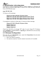
7.3.2 Virtual Server
Click on Advanced Setup then NAT.
Click on Virtual Server.
A02-RA142-W54
Pag. 52
WebShare 142W
The following table describes the labels in this screen.
Label
Description
Start Port No.
Enter a port number in this field.
To forward only one port, enter the port number again in the
End Port No. field.
To forward a series of ports, enter the start port number here
and the end port number in the End Port No. field.
End Port No.
Enter a port number in this field.
To forward only one port, enter the port number again in the
Start Port No. field above and then enter it again in this field.
To forward a series of ports, enter the last port number in a
series that begins with the port number in the Start Port No.
field above.
IP Address
Enter your server IP address in this field.
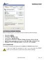
Let's say you want to assign ports 22-25 to one server, port 80 to another and
assign a default server IP address of 192.168.1.35 as shown in the next figure.
A02-RA142-W54
Pag. 53
WebShare 142W
7.4 Selecting the NAT Mode
Click Advanced Setup then NAT to open the following screen chose Multiple
(Numbers of IP).
Click on IP Address Mapping (for Multiple IPs Service).
A02-RA142-W54
Pag. 54
WebShare 142W
Ordering your rules is important because the ADSL Router applies the rules in the
order that you specify. When a rule matches the current packet, the ADSL Router
takes the corresponding action and the remaining rules are ignored. If there are
any empty rules before your new configured rule, your configured rule will be
pushed up by that number of empty rules. For example, if you have already
configured rules 1 to 6 in your current set and now you configure rule number 9.
In the set summary screen, the new rule will be rule 7, not 9. Now if you delete
rule 4, rules 5 to 7 will be pushed up by 1 rule, so old rules 5, 6 and 7 become
new rules 4, 5 and 6.
To change the ADSL Router’s address mapping settings.
The following table describes the labels in this screen.
Label
Description
Rule Index
Chose the number
Rule Type
1-1: One-to-one mode maps one local IP address to one
global IP address. Note that port numbers do not change for
the One-to-one NAT mapping type.
M-1: Many-to-One mode maps multiple local IP addresses to
one global IP address.
M-M Ov (Overload): Many-to-Many Overload mode maps
multiple local IP addresses to shared global IP addresses.
MM No (No Overload): Many-to-Many No Overload mode
maps each local IP address to unique global IP addresses.
Server(available on next release of firmware): This type allows
you to specify inside servers of different services behind the
NAT to be accessible to the outside world.
Local Start IP
This is the starting Inside Local IP Address (ILA). Local IP
addresses are N/A for Server port mapping.
Local End IP
This is the end Inside Local IP Address (ILA). If your rule is for
all local IP addresses, then enter 0.0.0.0 as the Local Start IP
address and 255.255.255.255 as the Local End IP address.
This field is N/A for One-to-one and Server mapping types.
Public Start IP This is the starting Inside Global IP Address (IGA). Enter
0.0.0.0 here if you have a dynamic IP address from your ISP.
You can only do this for Many-to-One and Server mapping
types.
Public End IP
This is the ending Inside Global IP Address (IGA). This field is
N/A for One-to-one, Many-to-One and Server mapping types.
A02-RA142-W54
Pag. 55
WebShare 142W
A02-RA142-W54
Pag. 56
WebShare 142W
CHAPTER 8: Access Management
8.1 ACL
Access Control Listing allows you to determine which services/protocols can
access which WEBSHARE Wireless ROUTER ADSL2+ interface from which
computers.
You can configure the router for remote Telnet access or upload and download
router firmware and configuration files using FTP. To use this feature, your
computer must have an FTP client. And can use the WEBSHARE Wireless
ROUTER ADSL2+ embedded web configurator for configuration and file
management.
Field
ACL Rule Index
Secure
IP
Address
Application
Meaning
This is item number
The default 0.0.0.0 allows any client to use this service
to remotely manage the WEBSHARE Wireless
ROUTER ADSL2+. Type an IP address to restrict
access to a client with a matching IP address
Choose a service that you may use to remotely manage
the WEBSHARE Wireless ROUTER ADSL2+.
A02-RA142-W54
Pag. 57
WebShare 142W
Interface
Select the access interface. Choices are LAN, WAN
and Both
8.2 IP Filter
You may use telnet or Web to remotely manage the ADSL Router. User just
needs to enable Telnet or Web and give it an IP address that want to access the
ADSL Router. The default IP 0.0.0.0 allows any client to use this service to
remotely manage the ADSL Router.
IP FILTER SET EDITING:
Field
Meaning
This is item number
Ip Filter Set Index
A02-RA142-W54
Pag. 58
WebShare 142W
Select which channel (PVC) to configure
Select the access to the Internet (“Outgoing”) or from
the Internet (“Incoming”).or Both
Interface
Direction
IP FILTER RULE EDITING:
Field
Meaning
Ip Filter Rule This is item number
Index
Select Yes from the drop down list box to enable IP filter
Active
rule
Source
IP The source IP address or range of packets to be
monitored
Address
It is the destination IP addresses based on above
Subnet Mask
destination subnet IP
Source
Port This Port or Port Ranges defines the port allowed to be
used by the Remote/WAN to connect to the application.
Number
Default is set from range 0 ~ 65535. It is recommended
that this option be configured by an advanced user
Destination
IP This is the destination subnet IP address
Address
It is the destination IP addresses based on above
Subnet Mask
destination subnet IP
It is the packet protocol type used by the application,
Protocol
select either TCP or UDP or ICMP
Rule Unmatched Select action for the traffic unmatching current rule;
Forward to leave it pass through, and NEXT to check it by
the next rule
IP FILTER LIST:
Field
#
Active
Source IP Mask
IP
Meaning
Item number
Whether the connection is currently activ
The source IP address or range of packets to be
monitored
This is the destination subnet IP address
Destination Port
This Port or Port Ranges defines the port allowed to be
used by the Remote/WAN to connect to the application.
Default is set from range 0 ~ 65535. It is recommended
that this option be configured by an advanced user
This is the Port or Port Ranges that defines the application
Destination
Mask
Source port
A02-RA142-W54
Pag. 59
WebShare 142W
Protocol
It is the packet protocol type used by the application,
select either TCP or UDP or ICMP
8.3 SNMP
Simple Network Management Protocol (SNMP) is a protocol used for exchanging
management information between network devices. SNMP is a member of the
TCP/IP protocol suite. WebShare Wireless Router ADSL2+ supports SNMP
agent functionality which allows a manager station to manage and monitor the
router through the network.
Field
Get Community
Set Community
Meaning
Type the Get Community, which is the password for
the incoming Get-and GetNext requests from the
management station
Type the Set Community, which is the password for
incoming Set requests from the management station
8.4 UPnP
UPnP offers peer-to-peer network connectivity for PCs and other network
devices, along with control and data transfer between devices. UPnP offers many
advantages for users running NAT routers through UPnP NAT Traversal, and on
supported systems makes tasks such as port forwarding much easier by letting
the application control the required settings, removing the need for the user to
control advanced configuration of their device.
Both the user’s Operating System and the relevant application must support
UPnP in addition to the router. Windows XP and Windows Me natively support
UPnP (when the component is installed), and Windows 98 users may install the
Internet Connection Sharing client from Windows XP in order to support UPnP.
Windows 2000 does not support UPnP.
A02-RA142-W54
Pag. 60
WebShare 142W
Field
UPnP
Auto-Configured
Meaning
Select this checkbox to activate UPnP. Be aware
that anyone could use a UPnP application to open
the web configurator's login screen without entering
the WEBSHARE Wireless ROUTER ADSL2+ IP
address
Select this check box to allow UPnP-enabled
applications to automatically configure the
WEBSHARE Wireless ROUTER ADSL2+ so that
they can communicate through the WEBSHARE
Wireless ROUTER ADSL2+, for example by using
NAT traversal, UPnP applications automatically
reserve a NAT forwarding port in order to
communicate with another UPnP enabled device;
this eliminates the need to manually configure port
forwarding for the UPnP enabled application
8.5 DDNS
The Dynamic DNS function allows you to alias a dynamic IP address to a static
hostname, allowing users whose ISP does not assign them a static IP address to
use a domain name. This is especially useful for hosting servers via your ADSL
connection, so that anyone wishing to connect to you may use your domain
name, rather than having to use your dynamic IP address, which changes from
time to time. This dynamic IP address is the WAN IP address of the router, which
is assigned to you by your ISP.
You will first need to register and establish an account with the Dynamic DNS
provider using their website, for example http://www.dyndns.org/
A02-RA142-W54
Pag. 61
WebShare 142W
Field
Dynamic DNS
Service Provider
My Host Name
E-Mail Address
Username
Password
Wildcard
support
Meaning
Select this check box to use dynamic DNS
Select the name of your Dynamic DNS service provider
Type the domain name assigned to your WEBSHARE
Wireless ROUTER ADSL2+ by your Dynamic DNS
provider
Type your e-mail address
Type your user name
Type the password assigned to you
Select this check box to enable DYNDNS Wildcard
A02-RA142-W54
Pag. 62
WebShare 142W
CHAPTER 9: Advanced Setup
9.1 Routing
If you have another router with a LAN-to-LAN connection, you may create a static
routing on the router that is the gateway to Internet.
ROUTING TABLE LIST:
Field
Meaning
Item number
#
IP address of the destination network
Dest IP
Mask
Gateway IP
Metric
Device
Use
Edit
Drop
The destination mask address
IP address of the gateway or existing interface that this
route uses
It represents the cost of transmission for routing purposes.
The number need not be precise, but it must be between 1
and 15
Media/channel selected to append the route
Counter for access times
Edit the route; this icon is not shown for system default
route
Edit the route; this icon is not shown for system default
route
9.1.1 Add Route
A02-RA142-W54
Pag. 63
WebShare 142W
Field
Destination
Address
IP Subnet Mask
Gateway IP Address
Metric
Announced in RIP
IP
Meaning
This is the destination subnet IP address
It is the destination IP addresses based on above
destination subnet IP
This is the gateway IP address to which packets are
to be forwarded
It represents the cost of transmission for routing
purposes. The number need not be precise, but it
must be between 1 and 15
This parameter determines if the Prestige will
include the route to the remote node in its RIP
broadcasts. Set “Yes”, it is kept private and is not
included in RIP broadcasts. Set “No”, the remote
node will be propagated to other hosts through RIP
broadcasts
A02-RA142-W54
Pag. 64
WebShare 142W
9.2 NAT
The NAT (Network Address Translation - NAT, RFC 1631) is the translation of the
IP address of a host in a packet. The default setting is Dynamic NAPT. It
provides dynamic Network Address Translation capability between LAN and
multiple WAN connections, and the LAN traffic is routed to appropriate WAN
connections based on the destination IP addresses and Route Table. This
eliminates the need for the static NAT session configuration between multiple
LAN clients and multiple WAN connections.
Field
Meaning
VPI (Virtual Path Identifier) and VCI (Virtual Channel
Virtual Circuit
Identifier) define a virtual circuit. There are eight
groups of PVC can be defined and used
User can select Single or Multiple
Number of IPs
9.2.2 DMZ
The DMZ Host is a local computer exposed to the Internet. When setting a
particular internal IP address as the DMZ Host, all incoming packets will be
checked by the Firewall and NAT algorithms then passed to the DMZ host, when
a packet received does not use a port number used by any other Virtual Server
entries.
Field
Meaning
DMZ
Disabled: As set in default setting, it disables the
DMZ function.
Enabled: It activates your DMZ function
Give a static IP address to the DMZ Host when
DMZ Host Address
A02-RA142-W54
Pag. 65
WebShare 142W
Enabled radio button is checked. Be aware that this
IP will be exposed to the WAN/Internet.
Select the Apply button to apply your changes.
9.2.3 Virtual Server
In TCP/IP and UDP networks a port is a 16-bit number used to identify which
application program (usually a server) incoming connections should be delivered
to. Some ports have numbers that are pre-assigned to them by the IANA (the
Internet Assigned Numbers Authority), and these are referred to as “well-known
ports”. Servers follow the well-known port assignments so clients can locate them.
If you wish to run a server on your network that can be accessed from the
WAN (i.e. from other machines on the Internet that are outside your local
network), or any application that can accept incoming connections (e.g.
Peer-to-peer/P2P software such as instant messaging applications and P2P
file-sharing applications) and are using NAT (Network Address Translation),
then you will usually need to configure your router to forward these
incoming connection attempts using specific ports to the PC on your
network running the application. You will also need to use port forwarding if
you want to host an online game server.
The reason for this is that when using NAT, your publicly accessible IP address
will be used by and point to your router, which then needs to deliver all traffic to
the private IP addresses used by your PCs. Please see the WAN configuration
section of this manual for more information on NAT.
The device can be configured as a virtual server so that remote users accessing
services such as Web or FTP services via the public (WAN) IP address can be
automatically redirected to local servers in the LAN network. Depending on the
requested service (TCP/UDP port number), the device redirects the external
service request to the appropriate server within the LAN network.
Field
Rule Index
Start Port Number
End Port Number
Local IP Address
Meaning
Choose the rule number
Enter a port number in this field
Enter a port number in this field
Enter your server IP address in this field
A02-RA142-W54
Pag. 66
WebShare 142W
9.2.4 IP Address Mapping
Field
Rule Index
Rule Type
Local Start IP
Local End IP
Public Start IP
Public End IP
Meaning
Choose the rule number
One-to-one: This is the mode maps one local IP address
to one global IP address. Note that port numbers do not
change for the One-to-one NAT mapping type
Many-to-One: This is the mode maps multiple local IP
addresses to one global IP address. This is equivalent to
Many to One (i.e., PAT, port address translation)
Many-to-Many Overload: This is mode maps multiple
local IP addresses to shared global IP addresses
Many-to-Many No Overload: This is the mode maps
each local IP address to unique global IP addresses
Server: This type allows you to specify inside servers of
different services behind the NAT to be accessible to the
outside world
This is the starting Inside Local IP Address (ILA). Local IP
addresses are N/A for Server port mapping
This is the end Inside Local IP Address (ILA). If your rule
is for all local IP addresses, then enter 0.0.0.0 as the
Local Start IP address and 255.255.255.255 as the Local
End IP address. This field is N/A for One-to-one and
Server mapping types
This is the starting Inside Public IP Address. Enter 0.0.0.0
here if you have a dynamic IP address from your ISP
This is the ending Inside Public IP Address. This field is
N/A for One-to-one, Many-to-One and Server mapping
types
If you have disabled the NAT option in the WAN-ISP section, the Virtual
Server function will hence be invalid.
If the DHCP server option is enabled, you have to be very careful in
assigning the IP addresses of the virtual servers in order to avoid
conflicts. The easiest way of configuring Virtual Servers is to manually
assign static IP address to each virtual server PC, with an address that
does not fall into the range of IP addresses that are to be issued by the
DHCP server. You can configure the virtual server IP address manually,
but it must still be in the same subnet as the router.
A02-RA142-W54
Pag. 67
WebShare 142W
9.3 ADSL
Field
ADSL Mode
ADSL Type
Meaning
The default setting is Auto Sync-UP. This mode will
automatically detect your ADSL, ADSL2+, ADSL2,
G.dmt, G.lite, and T1.413. But in some area,
multimode cannot detect the ADSL line code well. If
it is the case, please adjust the ADSL line code to
G.dmt or T1.413 first. If it still fails, please try the
other values such as ALCTL, ADI, etc
There are five modes “Open Annex Type and
Follow DSLAM’s Setting”, ”Annex A”, ”Annex I”,
“Annex A/L”, ”Annex M” and “Annex A/I/L/M” that
user can select for this connection
A02-RA142-W54
Pag. 68
WebShare 142W
CHAPTER 10: Maintenance
10.1 Administration
In factory setting, the default password is atlantis, and that for user is also
password. You can change the default password to ensure that someone cannot
adjust your settings without your permission. Every time you change your
password, please record the password and keep it at a safe place.
Field
New Password
Confirm Password
Meaning
Type the new password in this field
Type the new password again in this field
10.2 Time Zone
The router does not have a real time clock on board; instead, it uses the Simple
Network Time Protocol (SNTP) to get the current time from an SNTP server
outside your network. Choose your local time zone. After a successful connection
to the Internet, the router will retrieve the correct local time from the SNTP server
you have specified. If you prefer to specify an SNTP server other than those in
the drop-down list, simply enter its IP address as shown above. Your ISP may
provide an SNTP server for you to use.
A02-RA142-W54
Pag. 69
WebShare 142W
Field
Synchronize time with
Time Zone
Daylight Saving
NTP Server Address
Meaning
Select the time service protocol that your time
server sends when you turn on the Router
Choose the time zone of your location. This will set
the time difference between your time zone and
Greenwich Mean Time (GMT)
Select this option if you use daylight savings time
Enter the IP address of your time server. Check with
your ISP/network administrator if you are unsure of
this information
10.3 Firmware
Your router’s “firmware” is the software that allows it to operate and provides all
its functionality. Think of your router as a dedicated computer, and the firmware
as the software it runs. Over time this software may be improved and modified,
and your router allows you to upgrade the software it runs to take advantage of
these changes.
To upgrade the firmware of WEBSHARE Wireless ROUTER ADSL2+, you should
download or copy the firmware to your local environment first. Press the
“Browse…” button to specify the path of the firmware file. Then, click “Upgrade”
to start upgrading. When the procedure is completed, WEBSHARE Wireless
ROUTER ADSL2+ will reset automatically to make the new firmware work.
A02-RA142-W54
Pag. 70
WebShare 142W
Field
New
Location
Browse
Upgrade
Firmware
Meaning
Type in the location of the file you want to upload in
this field or click Browse to find it
Click Browse... to find the .ras file you want to
upload. Remember that you must decompress
compressed (.zip) files before you can upload them
Click UPGRADE to begin the upload process. This
process may take up to two minutes
After two minutes, log in again and check your new firmware version in the
System Status screen.
If the upload was not successful, the following screen will appear. Click Back to
go back to the Firmware screen.
DO NOT power down the router or interrupt the firmware upgrading while
it is still in process. Improper operation could damage the router.
A02-RA142-W54
Pag. 71
WebShare 142W
10.4 SysRestart
Click SysRestart with option Current Settings to reboot your router (and restore
your last saved configuration).
If you wish to restart the router using the factory default settings (for example,
after a firmware upgrade or if you have saved an incorrect configuration), select
Factory Default Settings to reset to factory default settings.
You may also reset your router to factory settings by holding the small Reset
pinhole button on the back of your router in for 10-12 seconds whilst the router is
turned on.
10.5 Diagnostic
The Diagnostic Test page shows the test results for the connectivity of the
physical layer and protocol layer for both LAN and WAN sides.
A02-RA142-W54
Pag. 72
WebShare 142W
A02-RA142-W54
Pag. 73
WebShare 142W
CHAPTER 11: Status
11.1 Device Info
DEVICE INFORMATION:
Field
Meaning
This is the Firmware version
Firmware version
This is the MAC Address
MAC Address
LAN:
Field
Meaning
A02-RA142-W54
Pag. 74
WebShare 142W
LAN port IP address
LAN port IP subnet mask
LAN port DHCP role - Enabled, Relay or disabled
IP Address
Sub Net Mask
DHCP Server
WAN:
Field
Status
Virtual Circuit
Meaning
“Not connected” or “Connected”
There are eight groups of PVC can be defined
VPI: The valid range for the VPI is 0 to 255
VCI: The valid range for the VCI is 32 to 65535
Connection Type
VPI/VCI
IP Address
Subnet Mask
Name of the WAN connectio
Virtual Path Identifier and Virtual Channel Identifier
WAN port IP address
WAN port IP subnet mask
Default Gateway
The IP address of the default gateway
DNS Server
WAN port DHCP role - Enabled, Relay or disabled
ADSL:
Field
ADSL firmware ver
Line State
Annex Mode
Max TX Power
Meaning
This is the DSL firmware version associated with
your router
This is the status of your ADSL lin
To show the router’s type, e.g. Annex A, Annex B
This field displays the transmit output power level of
the ADSL Router.
11.2 System Log
Display system logs accumulated up to the present time. You can trace historical
information with this function.
11.3 Statistics
Read-only information here includes port status and packet specific statistics.
Also provided are "Transmit Statistics" and "Receive Statistics".
A02-RA142-W54
Pag. 75
WebShare 142W
ETHERNET:
Field
Interface
Transmit Frames
Transmit Multicast Frames
Transmit total Bytes
Transmit Collision
Transmit Error Frames
Meaning
This field displays the type of port
This field displays the number of frames
transmitted in the last second
This field displays the number of multicast
frames transmitted in the last second
This field displays the number of bytes
transmitted in the last second
This is the number of collisions on this port
This field displays the number of error packets
on this port
Receive Frames
This field displays the number of frames
received in the last second
Receive Multicast Frames
This field displays the number of multicast
frames received in the last second
Receive total Bytes
This field displays the number of bytes
received in the last second
Receive CRC Errors
This field displays the number of error packets
on this port
Receive Under-size Frames
This field displays the number of under-size
frames received in the last second
ADSL:
Field
Transmit total PDUs
Transmit total Error
Counts
Receive total PDUs
Receive total Error
Counts
Meaning
This field displays the number of total PDU
transmitted in the last secon
This field displays the number of total error
transmitted in the last second
This field displays the number of total PDU received in
the last second
This field displays the number of total error received in
the last second
A02-RA142-W54
Pag. 76
WebShare 142W
A02-RA142-W54
Pag. 77
WebShare 142W
APPENDIX A: Troubleshooting
This chapter covers potential problems and the corresponding remedies.
A.1 Using LEDs to Diagnose Problems
The LEDs are useful aides for finding possible problem causes.
A.1.1 Power LED
The PWR LED on the front panel does not light up.
STEPS
1
2
3
4
CORRECTIVE ACTION
Make sure that the ADSL Router’s power adaptor is connected
to the ADSL Router and plugged in to an appropriate power
source. Use only the supplied power adaptor.
Check that the ADSL Router and the power source are both
turned on and the ADSL Router is receiving sufficient power.
Turn the ADSL Router off and on.
If the error persists, you may have a hardware problem. In this
case, you should contact your vendor.
A.1.2 LAN LED
The LAN LED on the front panel does not light up.
STEPS
1
2
3
4
CORRECTIVE ACTION
Check the Ethernet cable connections between the ADSL
Router and the computer or hub.
Check for faulty Ethernet cables.
Make sure your computer’s Ethernet card is working properly.
If these steps fail to correct the problem, contact your local
distributor for assistance.
A.1.3 DSL LED
The DSL LED on the front panel does not light up.
STEPS
1
2
CORRECTIVE ACTION
Check the telephone wire and connections between the ADSL
Router DSL port and the wall jack.
Make sure that the telephone company has checked your phone
line and set it up for DSL service.
A02-RA142-W54
Pag. 78
WebShare 142W
3
4
Reset your ADSL line to reinitialize your link to the DSLAM. For
details, refer to the Maintenance chapter (web configurator) or
the System Information and Diagnosis chapter.
If these steps fail to correct the problem, contact your local
distributor for assistance.
A.2 Telnet
I cannot telnet into the ADSL Router.
STEPS
1
2
3
4
5
CORRECTIVE ACTION
Check the LAN port and the other Ethernet connections.
Make sure you are using the correct IP address of the ADSL
Router. Check the IP address of the ADSL Router.
Ping the ADSL Router from your computer.
If you cannot ping the ADSL Router, check the IP addresses of
the ADSL Router and your computer. Make sure your computer
is set to get a dynamic IP address; or if you want to use a static
IP address on your computer, make sure that it is on the same
subnet as the ADSL Router.
Make sure you entered the correct password. The default
password is “admin”.
If you have forgot your username or password, refer to Section
A.5.
If these steps fail to correct the problem, contact the distributor.
A.3 Web Configurator
I cannot access the web configurator.
STEPS
1
2
3
4
5
6
CORRECTIVE ACTION
Make sure you are using the correct IP address of the ADSL
Router. Check the IP address of the ADSL Router.
Make sure that there is not an console session running.
Check that you have enabled web service access. If you have
configured a secured client IP address, your computer’s IP
address must match it. Refer to the chapter on remote
management for details.
For WAN access, you must configure remote management to
allow server access from the Wan (or all).
Your computer’s and the ADSL Router’s IP addresses must be
on the same subnet for LAN access.
If you changed the ADSL Router’s LAN IP address, then enter
A02-RA142-W54
Pag. 79
WebShare 142W
7
8
the new one as the URL.
Remove any filters in LAN or WAN that block web service.
See also Section A.9.
The web configurator does not display properly.
STEPS
1
2
CORRECTIVE ACTION
Make sure you are using Internet Explorer 5.0 and later
versions.
Delete the temporary web files and log in again.
In Internet Explorer, click Tools, Internet Options and then click
the Delete Files ... button.
When a Delete Files window displays, select Delete all offline
content and click OK. (Steps may vary depending on the version
of your Internet browser.)
A.4 Login Username and Password
I forgot my login username and/or password.
STEPS
1
2
3
4
CORRECTIVE ACTION
If you have changed the password and have now forgotten it,
you will need to upload the default configuration file. This will
erase all custom configurations and restore all of the factory
defaults including the password.
Press the RESET button for five seconds, and then release it.
When the SYS LED begins to blink, the defaults have been
restored and the ADSL Router restarts. Or refer to the Resetting
the ADSL Router section for uploading a configuration file via
console port.
The default username is “admin”. The default password is
“atlantis”. The Password and Username fields are casesensitive. Make sure that you enter the correct password and
username using the proper casing.
It is highly recommended to change the default username and
password. Make sure you store the username and password in
a save place.
A.5 LAN Interface
I cannot access the ADSL Router from the LAN or ping any computer on the LAN.
STEPS
1
CORRECTIVE ACTION
Check the Ethernet LEDs on the front panel. A LAN LED should
A02-RA142-W54
Pag. 80
WebShare 142W
2
be on if the port is connected to a computer or hub. If the
10M/100M LEDs on the front panel are both off, refer to Section
A.1.2.
Make sure that the IP address and the subnet mask of the ADSL
Router and your computer(s) are on the same subnet.
A.6 WAN Interface
Initialization of the ADSL connection failed.
STEPS
1
2
3
CORRECTIVE ACTION
Check the cable connections between the ADSL port and the
wall jack. The DSL LED on the front panel of the ADSL Router
should be on.
Check that your VPI, VCI, type of encapsulation and type of
multiplexing settings are the same as what you collected from
your telephone company and ISP.
Restart the ADSL Router. If you still have problems, you may
need to verify your VPI, VCI, type of encapsulation and type of
multiplexing settings with the telephone company and ISP.
I cannot get a WAN IP address from the ISP.
STEPS
1
2
CORRECTIVE ACTION
The ISP provides the WAN IP address after authenticating you.
Authentication may be through the user name and password,
the MAC address or the host name.
The username and password apply to PPPoE and PPoA
encapsulation only. Make sure that you have entered the correct
Service Type, User Name and Password (be sure to use the
correct casing).
A.7 Internet Access
I cannot access the Internet.
STEPS
1
2
3
4
CORRECTIVE ACTION
Make sure the ADSL Router is turned on and connected to the
network.
If the DSL LED is off, refer to Section A.1.3.
Verify your WAN settings.
Make sure you entered the correct user name and password.
Internet connection disconnects.
A02-RA142-W54
Pag. 81
WebShare 142W
STEPS
1
2
3
CORRECTIVE ACTION
Check the schedule rules.
If you use PPPoA or PPPoE encapsulation, check the idle timeout setting.
Contact your ISP.
A.8 Remote Management
I cannot remotely manage the ADSL Router from the LAN or WAN.
STEPS
1
2
3
4
CORRECTIVE ACTION
Refer to the Remote Management Limitations section in the
Firmware and Configuration File Management chapter for
scenarios when remote management may not be possible.
Use the ADSL Router’s WAN IP address when configuring from
the WAN.
Use the ADSL Router’s LAN IP address when configuring from
the LAN.
Refer to Section A.6 for instructions on checking your LAN
connection.
Refer to Section A.7 for instructions on checking your WAN
connection.
See also the Section A.4.
A.9 Remote Node Connection
I cannot connect to a remote node or ISP.
STEPS
1
2
3
CORRECTIVE ACTION
Check WAN screen to verify that the username and password
are entered properly.
Verify your login name and password for the remote node.
If these steps fail, you may need to verify your login and
password with your ISP.
A02-RA142-W54
Pag. 82
WebShare 142W
A.10 FAQ
Question
Answer
Question
Answer
Can I run an application from a remote computer over the
wireless network?
This will depend on whether or not the application is designed
to be used over a network. Consult the application’s user
guide to determine if it supports operation over a network.
Can I play computer games with other members of the
wireless network?
Yes, as long as the game supports multiple players over a
LAN (local area network).
Refer to the game’s user guide for more information.
Question
Answer
What is Spread Spectrum?
Spread Spectrum technology is a wideband radio frequency
technique developed by the military for use in reliable, secure,
mission-critical communications systems. It is designed to
trade off bandwidth efficiency for reliability, integrity, and
security. In other words, more bandwidth is consumed than in
the case of narrowband transmission, but the trade-off
produces a signal that is, in effect, louder and thus easier to
detect, provided that the receiver knows the parameters of the
spread-spectrum signal being broadcast. If a receiver is not
tuned to the right frequency, a spread-spectrum signal looks
like background noise. There are two main alternatives, Direct
Sequence Spread Spectrum (DSSS) and Frequency Hopping
Spread Spectrum (FHSS).
Question
What is DSSS? What is FHSS? And what are their
differences?
Frequency-Hopping Spread-Spectrum (FHSS) uses a
narrowband carrier that changes frequency in a pattern that is
known to both transmitter and receiver. Properly
synchronized, the net effect is to maintain a single logical
channel. To an unintended receiver, FHSS appears to be
short-duration impulse noise. Direct-Sequence SpreadSpectrum (DSSS) generates a redundant bit pattern for each
bit to be transmitted. This bit pattern is called a chip (or
chipping code). The longer the chip, the greater the probability
that the original data can be recovered. Even if one or more
bits in the chip are damaged during transmission, statistical
techniques embedded in the radio can recover the original
Answer
A02-RA142-W54
Pag. 83
WebShare 142W
data without the need for retransmission. To an unintended
receiver, DSSS appears as low power wideband noise and is
rejected (ignored) by most narrowband receivers.
Question
Answer
Would the information be intercepted while transmitting on
air?
WLAN features two-fold protection in security. On the
hardware side, as with Direct Sequence Spread Spectrum
technology, it has the inherent security feature of scrambling.
On the software side, WLAN offers the encryption function
(WEP) to enhance security and access control.
Question
Answer
What is WEP?
WEP is Wired Equivalent Privacy, a data privacy mechanism
based on a 64-bit or 128-bit shared key algorithm, as
described in the IEEE 802.11 standard.
Question
Answer
What is infrastructure mode?
When a wireless network is set to infrastructure mode, the
wireless network is configured to communicate with a wired
network through a wireless access point.
Question
Answer
What is roaming?
Roaming is the ability of a portable computer user to
communicate continuously while moving freely throughout an
area greater than that covered by a single access point.
Before using the roaming function, the workstation must make
sure that it is the same channel number with the access point
of dedicated coverage area.
Question
Answer
What is ISM band?
The FCC and their counterparts outside of the U.S. have set
aside bandwidth for unlicensed use in the ISM (Industrial,
Scientific and Medical) band. Spectrum in the vicinity of 2.4
GHz, in particular, is being made available worldwide. This
presents a truly revolutionary opportunity to place convenient
high-speed wireless capabilities in the hands of users around
the globe.
A02-RA142-W54
Pag. 84
WebShare 142W
Question
Answer
What is the IEEE 802.11g standard?
Approved in June, 2003 as an IEEE standard for wireless
local area networks (WLANs), 802.11g offers wireless
transmission over relatively short distances at up to 54
megabits per second (Mbps) compared with the 11 megabits
per second of the 802.11b (Wi-Fi) standard. Like 802.11b,
802.11g operates in the 2.4 GHz range and is thus compatible
with it.
A02-RA142-W54
Pag. 85
WebShare 142W
APPENDIX B: Technical Features
Protocols
LAN port
WAN port
Antenna
Wireless
External buttons
LED Indicators
Standard ADSL
Compliance
Protocols ADSL
ATM
Firewall
VPN
Input Power
Power Consumption
Agency and Regulatory
Dimensions
Weight
Operating Temperature
Storage Temperature
Operating Humidity
IP, NAT, ARP, ICMP, IGMP, DHCP(server, client
and relay), RIP1/2 , SNTP client, UPnP, Telnet
server, SNMP
4 x RJ45 10/100 Base-T port
RJ-11 (1 port ADSL)
1*2.2dBi external fixed Antenna
IEEE802.11g/IEEE802.11b
Reset/Power Switch
Power, System, WLAN, 4 X Lan, ADSL and PPP
ANSI T1.413 Issue 2, ITU-T G.992.1(Full Rate
DMT), ITU-T G.992.2 (Lite DMT), ITU-T G.994.1
(Multimode), ITU G.992.3 (G.dmt.bis), ITU G.992.5
(G.dmt.bisplus)
RFC2364(PPPoA),
RFC2516(PPPoE)
and
RFC1483
ATM AAL2/AAL5 and ATM service class : CBR,
UBR, VBR-rt, VBR, ATM Forum UNI 3.0, 3.1 and
4.0
Packet Filtering (up to 72 rules) and NAT
Pass Through
12V DC @ 1A
< 9watts
CE
175 x 129 x 39 mm3
150g
0° to 40°C
-10° to 70°C
5-95% non-condensing
A02-RA142-W54
Pag. 86
WebShare 142W
APPENDIX C:Support
If you have any problems with the WebShare Wireless Router ADSL2+, please
consult this manual. If you continue to have problems you should contact the
dealer where you bought this ADSL Router. If you have any other questions you
can contact the Atlantis Land company directly at the following address:
Atlantis Land SpA
Viale De Gasperi, 122
20017 Mazzo di Rho(MI)
Tel: +39. 02.93906085, +39. 02.93907634(help desk)
Fax: +39. 02.93906161
Email: [email protected] or [email protected]
WWW: http://www.atlantis-land.com
A02-RA142-W54
Pag. 87