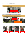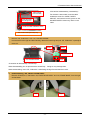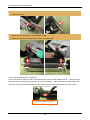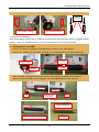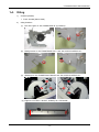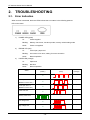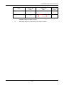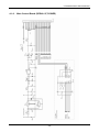
1
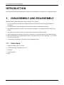
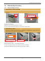
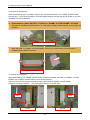
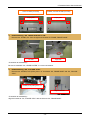
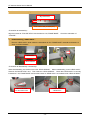
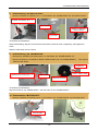
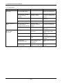
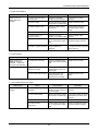
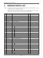
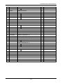
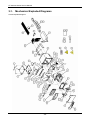
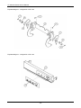
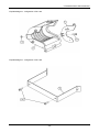
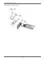
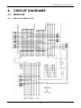
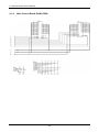
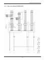
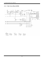
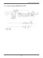
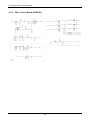
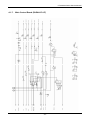
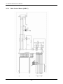
Service Manual
COMPACT LINE THERMAL PRINTER
CT-P292/293 Series
Revision 1.00 2010.2.15
CT-292/293 Series Service Manual
REVISIONS
Rev No.
Date
1.00
2010/2/15
Page
Comment
Newly issued
CITIZEN is a registered trademark of CITIZEN HOLDINGS CO., LTD., Japan.
CITIZEN es una marca registrada de Citizen Holdings Co., Japón.
-1-
CT-292/293 Series Service Manual
CONTENTS
INTRODUCTION .............................................................................................4
1.
2.
3.
DISASSEMBLY AND REASSEMBLY.......................................................4
1-1.
Tools Used .........................................................................................................................4
1-2.
Disassembly Procedure .....................................................................................................5
1-2-1.
Disassembling the Printer....................................................................................5
1-2-2.
Disassembling “UNIT, MECHANISM” ..................................................................8
1-3.
Assembly Procedure........................................................................................................16
1-4.
Oiling................................................................................................................................17
TROUBLESHOOTING ...........................................................................18
2-1.
Error Indication.................................................................................................................18
2-2
Explanations of Error Conditions......................................................................................20
2-2-1
Head Overheat Error .........................................................................................20
2-2-2
Cover Open Error ..............................................................................................20
2-2-3
Cutter Lock Error ...............................................................................................20
2-2-4
Memory Check Error..........................................................................................20
2-2-5
Low Voltage Error ..............................................................................................20
2-2-6
High Voltage Error .............................................................................................20
2-2-7
Paper End..........................................................................................................20
2-2-8
Macro Execution Wait ........................................................................................20
2-3.
Troubleshooting Procedure..............................................................................................21
2-4.
Troubleshooting Guide.....................................................................................................21
SERVICE PARTS LIST ..........................................................................24
3-1.
Mechanical Exploded Diagrams.......................................................................................26
-2-
CT-292/293 Series Service Manual
4.
CIRCUIT DIAGRAMS.............................................................................31
4-1.
MAIN PCB .......................................................................................................................31
4-1-1.
Main Control Board (CPU).................................................................................31
4-1-2.
Main Control Board (RAM, ROM) ......................................................................32
4-1-3.
Main Control Board (EXTEND PORT) ...............................................................33
4-1-4.
Main Control Board (HEAD) ..............................................................................34
4-1-5.
Main Control Board (FEED MOTOR, CUTTER) ................................................35
4-1-6.
Main Control Board (SENSOR) .........................................................................36
4-1-7.
Main Control Board (PARALLEL I/F)..................................................................37
4-1-8.
Main Control Board (USB I/F)............................................................................38
4-1-9.
Main Control Board (SERIAL I/F, POWER)........................................................39
-3-
CT-292/293 Series Service Manual
INTRODUCTION
This manual describes the disassembly, reassembly, and maintenance procedures of CT-P292/293 Series.
1.
DISASSEMBLY AND REASSEMBLY
Note the following items when performing maintenance of the printer.
• Do not disassemble, reassemble, or adjust the printer unnecessarily when the printer operation is
satisfactory.
• Do not loosen the screws that fasten the components unless it is absolutely necessary.
• After finishing inspection, perform a check to ensure that there is no irregularity before turning on the
printer.
• Use caution not to leave any part or screw used for maintenance inside the printer.
• When handling the print head and electronic components, care must be taken to avoid static electricity.
• When disassembling or reassembling the printer, check the wires and cords for damage. Do not draw
any wire or cord by force.
• Lubricate the components as necessary when reassembling them.
1-1.
Tools Used
• Phillips screwdriver #0, #1, and #2
• Precision flat head screwdriver (2.0 mm)
• Tweezers
• Long-nose pliers
• Brush
-4-
CT-292/293 Series Service Manual
1-2.
Disassembly Procedure
1-2-1.
Disassembling the Printer
1.
Disassembling “COVER, OPE-PANE”
Press in the lugs on the right and left at “COVER, OPE-PANE” and remove “COVER, OPE-PANE”
toward you.
Lugs
COVER, OPE-PANE
<Precaution at reassembly>
Engage the lugs at “COVER OPE-PANE” to “CASE L”.
Try to pull “COVER OPE-PANE” toward you to check that it is securely fitted.
2.
Disassembling “CASE L”
Remove two “SCREW, PHT (ST#3), M3.0 × 6” that fasten “SA, FRAME BASE”, and pull it toward you
while holding the both edges of “SA, DOOR FRONT”.
Metallic parts
SCREW, PHT (ST#3), M3.0 × 6
SA, DOOR FRONT
<Precaution at reassembly>
When reassembling “CASE L”, put it smoothly without hitch.
If it cannot be inserted smoothly, pull it toward you and insert it back again.
Check that the metallic part comes into view through the holes at “CASE L”.
-5-
CT-292/293 Series Service Manual
3.
Disassembling “DOOR FRONT”
Flip down “SA, DOOR FRONT” toward you.
Remove “E-RING, 2.0” that fasten “LINK, FRONT DOOR” and “SA, LEVER PLATEN” at the right and
left, and disengage “LINK, FRONT DOOR” from “DOOR FRONT”.
SA, LEVER PLATEN
E-RING, 2.0
LINK, FRONT DOOR
<Precaution at disassembly / reassembly>
Keep the bosses at “LINK, FRONT DOOR” facing inwardly and hang them to “DOOR FRONT”. Put “LINK,
FRONT DOOR” to the pins at “SA, LEVER PLATEN” and secure it using “E-RING”.
Open “DOOR FRONT” and detach it from the shaft at “HOLDER PAPER”.
On the left side, align the grooves at the shaft with the notches at “DOOR FRONT”, and slide “DOOR
FRONT” to the right to remove it.
Right
Left
Align the grooves.
<Precaution at disassembly / reassembly>
Note that the left side of “DOOR FRONT” can be inserted or removed only in a correct orientation.
When reassembling, insert the right side first, then the left side.
-6-
CT-292/293 Series Service Manual
4.
Disassembling “UNIT, MAIN PCB”
Remove four “SCREW, PHT (ST#3), M3.0 × 6”, and detach “UNIT, MAIN PCB” that is secured between
“PLATE SHIELD” and “SA, FRAME BASE”.
SCREW, PHT (ST#3), M3.0 × 6
PLATE SHIELD
UNIT, MAIN PCB
Raise the front edge of “UNIT, MAIN PCB” and disconnect “FFC CABLE” from the connectors at the
“HEAD ASSY” side and the “UNIT, MAIN PCB” side. Then, remove the other connectors and cut the
cable tie.
Auto-cutter model (CT-P293) only
CN4: CUTTER
Route the cable away
from the frame edge.
CN5: COVER SW
CN3: PE
CN3: MOTOR
HEAD ASSY
Cable tie
COVER SW
<Precaution at disassembly / reassembly>
When connecting or disconnecting “FFC CABLE”, keep it straight. Insert “FFC CABLE” while facing the
character-printed side upward.
When routing the cable for “COVER SW”, keep the cable away from the frame edge and do not tie it together
with any other cables.
Secure the other cables using a cable tie. (Loop back the motor cable only.)
Be careful not to allow the cables to get caught unnecessarily.
-7-
CT-292/293 Series Service Manual
1-2-2.
1.
Disassembling “UNIT, MECHANISM”
Disassembling “SA, HOLDER PAPER”
Remove “SCREW, PHT (BT#3), M3.0 × 8”, that fasten “SA, FRAME BASE” and “SA, HOLDER PAPER”,
from the right and left sides, respectively.
SCREW, PHT (BT#3), M3.0 × 8
<Precaution at reassembly>
Securely fit the bosses at “SA, HOLDER PAPER” into the slots at “SA, FRAME BASE”.
Remove “CUTTER CABLE” from the groove at “SA, HOLDER PAPER”, and draw it out from the hole.
Move “SA, HOLDER PAPER” along the groove at “SA, FRAME BASE” and remove it.
Remove the cable
from this groove.
Draw out “CUTTER CABLE”
from this hole.
Auto-cutter model (CT-P293) only
<Precaution at disassembly / reassembly>
Fit the boss at “FRONT DOOR ASSY” into the hole at “SA, HOLDER PAPER”.
Fit the boss in the following procedure.
Fit the projection
at the gear here.
Fit the opposite
boss here.
Fit the boss into
the hole.
-8-
Fit the boss into
the hole.
CT-292/293 Series Service Manual
<Precaution at disassembly / reassembly>
Take up slack
from the cable.
For the auto-cutter model, route the cable
outside the screw for “GUIDE, PAPER
ADJUST”, and insert it into the groove at “SA,
HOLDER PAPER” without any slack on the
cable.
Insert the cable
into this groove.
Route the cable outside the screw.
Auto-cutter model (CT-P293) only
Remove “PE, PCB ASSY” from “SA, HOLDER PAPER”.
Pull the hooks at the right and left outwardly, detach the lower lugs and pull “PE, PCB ASSY” upwardly to
remove it.
Hooks
Hooks
PE, PCB ASSY
Lugs
SA, HOLDER PAPER
<Precaution at disassembly / reassembly>
When disassembling, do not pull the hooks excessively. Doing so may damage them.
When reassembling, insert “PE, PCB ASSY” while fitting the lugs first and then the hooks.
2.
Disassembling “SA, FRONT DOOR ASSY”
Remove “E-RING, 2.0”, that fasten “SA, FRONT DOOR ASSY” and “SA, FRAME BASE”, from the right
and left sides.
Left
Right
-9-
CT-292/293 Series Service Manual
Detach the boss at “SA, FRAME BASE” from “FRAME, FRONT DOOR” while pulling “FRAME, FRONT
DOOR” outwardly.
Detach two lugs that fasten “GUIDE FRONT DOOR”.
Detach two lugs from the right and left sides of the platen roller.
<Precaution at disassembly / reassembly>
For the auto-cutter model, the cable is secured with the hook at “GUIDE FRONT DOOR”. When removing
the cable, remove it while pushing the hook in the arrow direction. When attaching the cable, make it flat
and insert it into the hook while pulling the cable toward the connector side to avoid slack on the cable.
Auto-cutter model (CT-P293) only
- 10 -
CT-292/293 Series Service Manual
Remove “SPRING, PLATEN LOCK” from the right and left sides of “FRAME, FRONT DOOR”.
Face them
inwardly.
SA, LEVER PLATEN L
SA, LEVER PLATEN R
<Precaution at reassembly>
When reassembling, keep the end of “SPRING, PLATEN LOCK” facing inwardly under the “FRAME, FRONT
DOOR”. Press “SA, LEVER PLATEN L & R” and check that they can be moved smoothly.
3.
Disassembling “PLATEN”
Remove “E-RING, 4.0” that fasten “PLATEN GEAR”, and pull out “PLATEN GEAR”.
Remove two “E-RING, 4.0” that fasten “PLATEN” and “PLATEN BUSH” at the right and left sides.
E-RING
PLATEN GEAR
PLATEN
E-RING
Move “PLATEN” to the right and pull it out from the shaft support at “FRAME, FRONT DOOR”.
When removing “PLATEN”, pull it out together with “PLATEN BUSHING” to the upper left.
Left
Move “PLATEN”
to the right.
Right
PLATEN BUSHING
Pull out “PLATEN” to the upper left.
PLATEN
- 11 -
CT-292/293 Series Service Manual
<Precaution at reassembly>
When reassembling, insert “PLATEN”, together with “PLATEN BUSHING”, into “FRAME, FRONT DOOR”
from the right. Since the shaft length of “PLATEN” differs between the right and left, be careful not to insert
“PLATEN” in a wrong orientation.
4.
Disassembling “AUTO CUTTER” (CT-P293) or “DUMMY, CUTTER FRAME” (CT-P292)
Remove two “SCREW, PHT (ST#3), M3.0 × 6”, that fasten “FRAME, FRONT DOOR”, from the right and
left sides.
SCREW, PHT (ST#3), M3.0 × 6
Slide “CUTTER” or “DUMMY, CUTTER FRAME”, and remove it while holding the side frames of
“FRAME, FRONT DOOR” outwardly.
Check the orientation.
<Precaution at reassembly>
When reassembling, pull “FRAME, FRONT DOOR” outwardly and slide “CUTTER” or “DUMMY, CUTTER
FRAME” onto “FRAME, FRONT DOOR” from a slanting direction.
Align the holes with the internal bosses at the right and left sides of “FRAME, FRONT DOOR”.
Check the mounting orientation. (The paper guide faces the “PLATEN” side.)
BOSS
BOSS
Left side
Left side
- 12 -
CT-292/293 Series Service Manual
AUTO CUTTER (CT-P293)
DUMMY, CUTTER FLAME (CT-P292)
Paper guide
5.
Paper guide
Disassembling “SA, LEVER PLATEN L & R”
Remove two “E-RING, 2.0” from the right and left sides of “FRAME, FRONT DOOR”.
Left side
Right side
<Precaution at reassembly>
Be sure to assemble “SA, LEVER PLATEN” in a correct orientation.
6.
Disassembling “SA, F BLADE STAY”
Remove two “SCREW, PHT (ST#3), M3.0 × 6” that fasten “SA, FRAME BASE” and “SA, F BLADE
STAY”.
SCREW, PHT (ST#3), M3.0 × 6
Align the bosses.
<Precaution at reassembly>
Align the bosses at “SA, F BLADE STAY” with the holes at “SA, FRAME BASE”.
- 13 -
CT-292/293 Series Service Manual
Remove “SCREW BHT (ST), M2.0 × 4” that fastens “SA, F BLADE STAY” and “F-BLADE”.
Align the bosses.
Auto-cutter model (CT-P293) only
<Precaution at reassembly>
Align the bosses at “F BLADE STAY” with the holes at “SA, FRAME BASE”. Check the orientation of
“F-BLADE”.
7.
Disassembling “HEAD ASSY”
Remove “HEAD ASSY” while pulling the side edges at “SA, FRAME BASE” outwardly and keeping it
clear of “HEAD SPRING”.
HEAD ASSY
HEAD SPRING
<Precaution at disassembly / reassembly>
When disassembling, be careful not to loose “HEAD SPRING”. When reassembling, mount “HEAD ASSY”
first and “SA, BLADE STAY” next. Then insert two “HEAD SPRING”. Check that “HEAD ASSY” is correctly
inserted into “SA, FRAME BASE” and that the bosses at “HEAD ASSY” are located inside “HEAD SPRING”.
Insert “HEAD ASSY”
into the window hole.
Check the bosses at
“HEAD ASSY”.
- 14 -
CT-292/293 Series Service Manual
8.
Disassembling “PE SWITCH ASSY”
Remove “SCREW, PHT (BT#3), M1.7 × 6” that fastens “SA, FRAME BASE” and “PE SWITCH ASSY”.
SCREW, PHT (BT#3), M1.7 × 6
Hole for screw
Keep the cable away
from the frame.
Hole for boss
<Precaution at reassembly>
When reassembling, align the screw and the boss with the holes for them, respectively, then tighten the
screw.
Keep the cable away from the frame.
9.
Disassembling “SA, FRAME BASE”
Remove two “SCREW, PHT (ST#3), M3.0 × 6” that fasten “SA, FRAME BASE R & L”.
Remove “E-RING, 2.0” and detach “GEAR1, REDUCTION” from “SA, FRAME BASE R”. Then remove
“REDUCTION GEAR”.
E-RING 2.0
SCREW, PHT (ST#3), M3.0 × 6
GEAR1, REDUCTION
Hole for boss
REDUCTION GEAR
<Precaution at reassembly>
Align the bosses at “SA, FRAME BASE L” with the holes at “SA, FRAME BASE R”.
10. Disassembling “MOTOR ASSY”
Remove “SCREW, PHT (ST#3), M3.0 × 6” that fastens “SA, FRAME BASE R” and “MOTOR ASSY”.
MOTOR ASSY
- 15 -
CT-292/293 Series Service Manual
<Precaution at reassembly>
Turn “MOTOR ASSY” and insert the lower flange into the fixture. Then secure “MOTOR ASSY” with a screw.
1-3.
Assembly Procedure
When reassembling the parts, follow the procedure of “1-2 Disassembly Procedure” in reverse.
- 16 -
CT-292/293 Series Service Manual
1-4.
Oiling
1)
Oil Used (Grease)
• FLOIL G-602S (Kanto Kasei)
2)
Oiling Positions
(1)
Pins at the gear on “SA, FRAME BASE R” (2 positions)
(2)
Mating section of “SA, FRAME BASE R & L” and “SA, LEVER PLATEN R & L”
(3)
Slideways at “SA, FRAME FRONT DOOR” and “SA, LEVER PLATEN R & L”
(4) Edges at “CUTTER F- BLADE”, slideways for “FIX BLADE”
- 17 -
CT-292/293 Series Service Manual
2.
TROUBLESHOOTING
2-1.
Error Indication
When an error is detected, the three LEDs indicate the error status in the following patterns.
LED on the panel
1)
2)
3)
POWER LED (green)
Lit:
Power supplied
Blinking:
Memory check error, hex-dump mode, memory switch setting mode
Not lit:
Power not supplied
ERROR LED (red)
Lit:
Cover open, paper end
Blinking:
Occurrence of an error, waiting for macro execution
Not lit:
Normal operation
PAPER LED (orange)
Lit:
Paper end
Blinking:
Not blink
Not lit:
Normal operation
Status
Head overheat
Cover open error *1
(MSW3-8 is set to OFF.)
Cover open error *2
(MSW3-8 is set to ON.)
Cutter lock error
POWER LED
ERROR LED
PAPER LED
(Green)
(Red)
(Orange)
Lit
−
Lit
−
Lit
−
Lit
−
Memory check error
Low voltage error
High voltage error
−
−
Lit
−
Lit
−
- 18 -
CT-292/293 Series Service Manual
Status
Paper end
Macro execution wait
*1, 2:
POWER LED
ERROR LED
PAPER LED
(Green)
(Red)
(Orange)
Lit
−
Lit
Lit
When the front cover is opened during paper feed or printing, the paper sensor may be
activated, resulting in the paper end error.
*2:
After closing the front cover, reset the error by using a command.
- 19 -
CT-292/293 Series Service Manual
2-2
Explanations of Error Conditions
2-2-1
Head Overheat Error
When the head temperature is raised (approx. 75°C or above), the ERROR LED blinks and printing operation
is stopped to protect the print head from overheat.
When the head temperature is lowered (approx. 70°C or lower), printing operation is automatically restarted.
2-2-2
Cover Open Error
When the front cover is opened during paper feed or printing, the ERROR LED blinks.
When MSW3-8 is set to OFF:
The error is reset when the front cover is closed (auto restore).
When MSW3-8 is set to ON:
The error is reset when the front cover is closed and a command is given.
Note: When the front cover is opened during paper feed or printing, the paper sensor may be activated, resulting in the
paper end error.
2-2-3
Cutter Lock Error
The cutter cannot be moved. An error has occurred.
To reset the error, remove the cause of the error, and press the FEED switch or give a command.
2-2-4
Memory Check Error
Memory read/write check operation is not correctly performed. (Restoration not possible)
2-2-5
Low Voltage Error
The voltage supplied to the printer drops.
When this error occurs, immediately turn the power off.
2-2-6
(Restoration not possible)
High Voltage Error
The voltage supplied to the printer rises excessively.
When this error occurs, immediately turn the power off.
2-2-7
(Restoration not possible)
Paper End
When the paper has run out, the paper sensor in the paper path is activated, the ERROR and PAPER LEDs
light up, and then printing operation is stopped.
Open the front cover and set new paper.
2-2-8
Macro Execution Wait
When the ESC/POS command is specified, the macro execution wait state will take effect. Press the FEED
switch.
- 20 -
CT-292/293 Series Service Manual
2-3.
Troubleshooting Procedure
When a fault occurs, confirm its phenomenon, locate the problem in accordance with “2.2 Troubleshooting
Guide”, and troubleshoot it as described below.
Phenomenon
Find the fault phenomenon in this column. If there are multiple phenomena, take all the applicable
items into consideration. This will help you locate hidden problems as well.
Cause
Possible causes are listed here. Find probable causes from the list and follow the check method to
identify the cause of the fault.
Check Method
The check method for identifying the cause of the fault is described.
Remedies
Take the remedies described in this column.
By following the above-mentioned procedure, you can troubleshoot problems efficiently with fewer
misjudgments.
2-4.
Troubleshooting Guide
● Power Supply Failure
Phenomenon
Cause
Power cannot be turned
on.
The power cable is not
connected. (AT model)
(The POWER LED not
illuminated.)
The main power of the power
source is off.
A cable is disconnected.
Check Method
Remedies
Check if the plug is correctly Connect the power cable.
connected.
Turn the main power on.
Check if the main power is
turned on.
Check if a cable at the power Replace the wire connected
supply line is disconnected
from the power source with a
using a tester.
new one. Modify the
damaged wire.
−
The control PCB is faulty.
- 21 -
Replace “UNIT, MAIN PCB”.
CT-292/293 Series Service Manual
● Printing Failure
Phenomenon
No printing
Cause
Check Method
The control PCB is faulty.
The thermal head connector
has a bad contact or
connection.
−
Check the contact or
connecting condition.
The thermal head is faulty.
Paper setting is wrong side
out.
Part of printing is not
done.
Print is pale.
Print is uneven.
Print is faint.
−
Remedies
Replace “UNIT, MAIN PCB”.
Re-insert the thermal head
connector or replace it with a
new one.
Replace the thermal head with
a new one.
Check the paper orientation. Set the paper correctly.
The thermal head connector
Check the contact,
has a bad contact or
connecting or mounting
connection or faulty mounting. condition.
Re-insert the thermal head
connector or “HEAD ASSY”.
The thermal head is faulty.
Replace the thermal head with
a new one.
The supply voltage is low.
−
Check the supply voltage
with a tester.
The thermal head is faulty.
−
Use the printer within the
specified supply voltage
range.
Replace the thermal head with
a new one.
The thermal head has fouling. Check the thermal head for
fouling.
Remove fouling using ethyl
alcohol soaked cotton swab or
soft cloth.
Paper other than
recommended is used.
Check if the paper being
used meets the
specification.
Replace it with the specified
paper.
The platen roller is not
mounted correctly.
Check the mounting
Mount the platen roller
condition of the platen roller. correctly.
- 22 -
CT-292/293 Series Service Manual
● Paper Feed Failure
Phenomenon
Paper is not fed.
Paper feed is not
straight.
Cause
Check Method
Remedies
The motor connector has a
bad connection.
Check the connecting
condition of the connector.
The motor is faulty.
Measure the supply voltage Replace “MOTOR ASSY”.
with a tester or oscilloscope.
The supply voltage is low.
Check the supply voltage
with a tester.
−
The control PCB is faulty.
Connect the connector
correctly.
Use the printer within the
specified supply voltage
range.
Replace “UNIT, MAIN PCB”.
The platen roller is not
mounted correctly.
Check the mounting
Mount the platen roller
condition of the platen roller. correctly.
Paper feed is faulty.
Check if paper is jammed,
torn or caught in the paper
path.
Foreign substances are stuck Check the gear for any
in the gear. A gear is broken. foreign substance or
breakage.
Remove unnecessary paper
and set the paper correctly.
Eliminate foreign substance.
If any gear is broken, replace it
with a new one.
● Faulty Sensor
Phenomenon
Paper presence or
absence cannot be
detected. Paper near
end cannot be detected.
Cause
The paper sensor is faulty.
An error cannot be reset. The sensor at the operation
panel cover is faulty.
Check Method
Remedies
Check the indication at the
Replace “SA, PE PCB”.
LCD or LED when the paper
ends.
Correctly attach the
operation panel cover and
check again.
The front cover switch is faulty. After setting paper and
closing the front cover,
check if the error is reset.
Replace “UNIT, MAIN PCB”.
Replace the front cover
switch.
● Auto Cutter Failure (CT-P293)
Phenomenon
Cause
The auto cutter does not The connector has a bad
operate.
connection.
The auto cutter is faulty.
Check Method
Check the connecting
Connect the connector
condition of the connector at correctly.
the control PCB.
Measure the supply voltage If the supply voltage is normal,
with a tester or oscilloscope. replace the auto cutter with a
new one.
−
The control PCB is faulty.
Paper feed is faulty.
(paper jams)
Remedies
Check if paper is jammed,
torn or caught in the paper
path.
- 23 -
Replace “UNIT, MAIN PCB”.
Remove unnecessary paper
and set the paper correctly.
CT-292/293 Series Service Manual
3.
SERVICE PARTS LIST
Remarks:
All the parts used in the product are contained in “SERVICE PARTS LIST” in this Service Manual. However,
note that all of them are not available with customers.
When placing an order for service parts, refer to the Parts Price List published separately. If you need the
Parts Price List, consult the local distributor from whom you purchased this product.
No.
Part No.
Part Name
Q’ty
Remarks
1
SA, FRAME BASE R
1
Not supplied
2
SA, FRAME BASE L
1
Not supplied
3
DW25901-00F
CUTTER STEP MOTOR ASSY
1
4
600377-00
REDUCTION GEAR (CTS-300)
1
5
ZH20201-00F
GEAR 1, REDUCTION
1
STAY, F BLADE
1
7
(500318-00)
(F-Blade-31 SEC3699)
1
8
100107-00
HEAD ASSY
1
9
700021-00
HEAD SPRING (CTS-300)
2
10
25-0347
FFC (SEC2310)
1
11
200036-000
PE Switch Assy (SEC3789)
1
ZH66702-00F
SA, PE PCB
6
12
13
HOLDER, PAPER
1
Not supplied
Not supplied
1
14
GUIDE, PAPER ADJUST
1
Not supplied
15
FRAME, FRONT DOOR
1
Not supplied
16
SA, LEVER PLATEN L
1
Not supplied
17
SA, LEVER PLATEN R
1
Not supplied
18
ACS530 Cutter (with Fix Brade)
(1)
for CT-P293
Not supplied
19
DUMMY, CUTTER FRAME
(1)
for CT-P292
Not supplied
20
CUTTER, MANUAL
(1)
for CT-P292
Not supplied
21
GUIDE, EX PAPER
(1)
for CT-P293
Not supplied
22
800452-00
PLATEN (CTS-300)
1
23
650001-00
PLATEN BUSHING (CTS-300)
2
24
600376-00
PLATEN GEAR (CTS-300)
1
25
ZH24203-00F
GUIDE, FRONT DOOR
1
26
ZH43601-00F
SPRING, PLATEN LOCK
2
27
ZH54202-00F
DOOR, FRONT
1
28
RINK, FRONT DOOR
2
29
ZH66801-00F
UNIT, MAIN PCB (WITH ROM)
(1)
30
ZH66802-00F
UNIT, MAIN PCB USB (WITH ROM)
(1)
Not supplied
for USB model
31
PLATE, SHIELD
1
Not supplied
32
CASE L
1
Not supplied
33
COVER, OPE-PANE
1
Not supplied
34
SHEET, OPE-PANE
1
Not supplied
CAUTION LABEL PAPER
1
Not supplied
CAUTION HOT
1
35
36
37
80-0276
CAUTION EDGE
1
- 24 -
Not supplied
CT-292/293 Series Service Manual
No.
Part No.
38
Part Name
PLATE,MOUNTING 292
39
25-0355
CORD ASSY CA212-5
40
ZH67901-00F
CORE, I/F CABLE
Q’ty
1
Remarks
Not supplied
(1)
1
41
36AD2-J
(1)
OPTION
42
SA, POWER BOARD
(1)
for AT model, Not supplied
43
COVER, POWER CON BOARD
(1)
for AT model, Not supplied
44
SA, I/F CABLE HOSIDEN
(1)
for AT model, Not supplied
45
CLAMP, WIRE
1
OPTION
46
CD-ROM, USER’S MANUAL JPN/ENG
1
OPTION
47
PAPER, ROLL
1
OPTION
UNIT, BOX CTP290
1
48
ZH76701-00F
49
AC CORD J
(1)
for JAPAN, OPTION
50
AC CORD U
(1)
for USA, OPTION
51
TA44114-00F
COVER FF, OPE-PANE
1
52
GUIDE, QUICK START JPN
(1)
OPTION
53
GUIDE, QUICK START ENG
(1)
OPTION
101
E11830-060F
SCREW, PHT (INT.TW) M3 × 6 (toothed lock)
1
102
E11126-060F
SCREW, PH (ST#3) M2.6 × 6
1
103
E11717-060F
SCREW, PHT (BT#3), M1.7 × 6
1
104
E11130-060F
SCREW, PHT (ST#3), M3 × 6
12
105
E14020-040F
SCREW, BHT (ST), M2 × 4
107
5
SCREW, PHT, M3 × 12
106
E11730-080F
SCREW, PHT (BT#3), M3 × 8
1
2
108
SCREW, PHT (ST#3), M3 × 12
2
109
SCREW, PHT (BT#3), M3 × 12
(2)
110
E60320-000F
E-RING, 2.0
7
111
E60340-00F
E-RING, 4.0
3
112
Not supplied
NUT, (#2) M3
Not supplied
for AT model Not supplied
1
Not supplied
201
ZH44710-00F
SA, ACS530 CUTTER
(1)
for CT-P293
202
ZH44709-00F
SA, DUMMY CUTTER
(1)
for CT-P292
203
ZH44708-00F
SA, FRONT DOOR FRAME
1
204
ZH54701-00F
SA, OPE-PANE COVER
1
205
ZH44707-00F
SA, HOLDER PAPER
1
206
ZH74701-00F
SA, MOUNTING PLATE
1
207
ZH67703-00F
SA, POWER BOARD-I/F CABLE HOSIDEN
- 25 -
(1)
for AT model
CT-292/293 Series Service Manual
3-1.
Mechanical Exploded Diagrams
Overall exploded diagram
- 26 -
CT-292/293 Series Service Manual
Exploded diagram - configuration of No. 201
Exploded diagram - configuration of No. 202
- 27 -
CT-292/293 Series Service Manual
Exploded diagram - configuration of No. 203
Exploded diagram - configuration of No. 204
- 28 -
CT-292/293 Series Service Manual
Exploded diagram - configuration of No. 205
Exploded diagram - configuration of No. 206
- 29 -
CT-292/293 Series Service Manual
Exploded diagram - configuration of No. 207
- 30 -
CT-292/293 Series Service Manual
4.
CIRCUIT DIAGRAMS
4-1.
MAIN PCB
4-1-1.
Main Control Board (CPU)
- 31 -
CT-292/293 Series Service Manual
4-1-2.
Main Control Board (RAM, ROM)
- 32 -
CT-292/293 Series Service Manual
4-1-3.
Main Control Board (EXTEND PORT)
- 33 -
CT-292/293 Series Service Manual
4-1-4.
Main Control Board (HEAD)
- 34 -
CT-292/293 Series Service Manual
4-1-5.
Main Control Board (FEED MOTOR, CUTTER)
- 35 -
CT-292/293 Series Service Manual
4-1-6.
Main Control Board (SENSOR)
- 36 -
CT-292/293 Series Service Manual
4-1-7.
Main Control Board (PARALLEL I/F)
- 37 -
CT-292/293 Series Service Manual
4-1-8.
Main Control Board (USB I/F)
- 38 -
CT-292/293 Series Service Manual
4-1-9.
Main Control Board (SERIAL I/F, POWER)
- 39 -