1
Owner's Manual
DMS-AV TSP2000E
Home Theater Amplifier
DMS-AV Owner’s Manual ©2012-2013 Universal Remote Control, Inc.
The information in this owner’s manual is copyright protected. No part of this
manual may be copied or reproduced in any form without prior written consent
from Universal Remote Control, Inc.
UNIVERSAL REMOTE CONTROL, INC. SHALL NOT BE LIABLE FOR OPERATIONAL, TECHNICAL OR EDITORIAL ERRORS/OMISSIONS MADE IN
THIS MANUAL.
The information in this owner’s manual may be subject to change without prior
notice.
URC - Control the Experience is a registered trademark of Universal Remote
Control, Inc.
Total Control is a registered trademark of Universal Remote Control, Inc.
All other brand or product names are trademarks or registered trademarks
of their respective companies or organizations
Universal Remote Control,Inc.
500 Mamaroneck Avenue, Harrison, NY 10528
Phone: (914) 835-4484 Fax: (914) 835-4532
DMS-AV HOME THEATER AMPLIFIER
IMPORTANT SAFETY INSTRUCTIONS . . . . . . . . . . . . . . . . . . . . . . . . 8
Cautions on Installation . . . . . . . . . . . . . . . . . . . . . . . . . . . . . . . . . . . . 8
Safety Precautions . . . . . . . . . . . . . . . . . . . . . . . . . . . . . . . . . . . . . . . . . 9
FCC INFORMATION . . . . . . . . . . . . . . . . . . . . . . . . . . . . . . . . . . . . . 12
Introduction / Overview . . . . . . . . . . . . . . . . . . . . . . . . . . . . . . . . . . . 12
DMS-AV Front Panel . . . . . . . . . . . . . . . . . . . . . . . . . . . . . . . . . . . . . . 13
DMS-AV Rear Panel . . . . . . . . . . . . . . . . . . . . . . . . . . . . . . . . . . . . . . 14
Quick Start Considerations . . . . . . . . . . . . . . . . . . . . . . . . . . . . . . . . 17
Connection Overview . . . . . . . . . . . . . . . . . . . . . . . . . . . . . . . . . . . . 20
Video Inputs - Hardware Connections . . . . . . . . . . . . . . . . . . . . . . . . 21
Video Input Connection – HDMI . . . . . . . . . . . . . . . . . . . . . . . . . 21
Video Input Connection - Component Video . . . . . . . . . . . . . . . . 21
Video Input Connection - Composite Video . . . . . . . . . . . . . . . . . 21
Video Outputs - Hardware Connections . . . . . . . . . . . . . . . . . . . . . . 22
Video Output Connection - HDMI . . . . . . . . . . . . . . . . . . . . . . . . 22
Video Output Connection - Component Video . . . . . . . . . . . . . . 22
Audio Inputs - Hardware Connections . . . . . . . . . . . . . . . . . . . . . . . 23
Audio Input Connection – HDMI . . . . . . . . . . . . . . . . . . . . . . . . . 23
Audio Input Connection - Optical Digital . . . . . . . . . . . . . . . . . . . 23
Audio Input Connection - Coax Digital . . . . . . . . . . . . . . . . . . . . . 23
Audio Input Connection - Stereo Analog . . . . . . . . . . . . . . . . . . . 23
Audio Output - Hardware Connections . . . . . . . . . . . . . . . . . . . . . . 24
Audio Output Connection – Unbalanced . . . . . . . . . . . . . . . . . . . 24
Audio Output Connection – Speakers . . . . . . . . . . . . . . . . . . . . . 24
Audio Output Connection – Subwoofer(s) . . . . . . . . . . . . . . . . . . 25
Audio Output Connection - Optical Digital Record . . . . . . . . . . . 25
Audio Output Connection - Analog Record . . . . . . . . . . . . . . . . . 25
Configuration and Control - Hardware Connections . . . . . . . . . . . . 26
Ethernet Communication - Connection Instructions . . . . . . . . . . . 26
Infrared Input . . . . . . . . . . . . . . . . . . . . . . . . . . . . . . . . . . . . . . . . . 26
Control Output Triggers / Amp Enable . . . . . . . . . . . . . . . . . . . . . . 27
Reset . . . . . . . . . . . . . . . . . . . . . . . . . . . . . . . . . . . . . . . . . . . . . . . . 27
Video Processing . . . . . . . . . . . . . . . . . . . . . . . . . . . . . . . . . . . . . . . . 27
Detail Enhancement . . . . . . . . . . . . . . . . . . . . . . . . . . . . . . . . . . . . 27
Mosquito Noise Reduction . . . . . . . . . . . . . . . . . . . . . . . . . . . . . . . 27
Edge Enhancement . . . . . . . . . . . . . . . . . . . . . . . . . . . . . . . . . . . . . 28
Page 4
DMS-AV HOME THEATER AMPLIFIER
HDMI Audio Output . . . . . . . . . . . . . . . . . . . . . . . . . . . . . . . . . . . 28
CEC Control . . . . . . . . . . . . . . . . . . . . . . . . . . . . . . . . . . . . . . . . . . 28
Auto A/V Sync . . . . . . . . . . . . . . . . . . . . . . . . . . . . . . . . . . . . . . . . . 28
Video PReP ® . . . . . . . . . . . . . . . . . . . . . . . . . . . . . . . . . . . . . . . . . 29
Video Test Patterns . . . . . . . . . . . . . . . . . . . . . . . . . . . . . . . . . . . . . 29
Frame Geometry . . . . . . . . . . . . . . . . . . . . . . . . . . . . . . . . . . . . . 29
Bright/Contrast . . . . . . . . . . . . . . . . . . . . . . . . . . . . . . . . . . . . . . 29
Checker board . . . . . . . . . . . . . . . . . . . . . . . . . . . . . . . . . . . . . . 30
Vertical Lines . . . . . . . . . . . . . . . . . . . . . . . . . . . . . . . . . . . . . . . 30
Horizontal Lines . . . . . . . . . . . . . . . . . . . . . . . . . . . . . . . . . . . . . 30
Judder . . . . . . . . . . . . . . . . . . . . . . . . . . . . . . . . . . . . . . . . . . . . . 30
Color 8 Bars 75 . . . . . . . . . . . . . . . . . . . . . . . . . . . . . . . . . . . . . 31
Color 8 Bars 100 . . . . . . . . . . . . . . . . . . . . . . . . . . . . . . . . . . . . 31
OSD Transparency . . . . . . . . . . . . . . . . . . . . . . . . . . . . . . . . . . . . . 31
Audio Modes and Speaker Selections . . . . . . . . . . . . . . . . . . . . . . . . 31
Audio/Surround Mode Usage . . . . . . . . . . . . . . . . . . . . . . . . . . . . . 31
On Screen Display (OSD) Format . . . . . . . . . . . . . . . . . . . . . . . . . . . 32
Momentary OSD . . . . . . . . . . . . . . . . . . . . . . . . . . . . . . . . . . . . . . 32
Software Setup - URC Accelerator . . . . . . . . . . . . . . . . . . . . . . . . . . . 32
DMS-AV System Settings – Audio . . . . . . . . . . . . . . . . . . . . . . . . . . . 32
Speaker Size/Speaker Crossover . . . . . . . . . . . . . . . . . . . . . . . . . . . 32
Front Speakers . . . . . . . . . . . . . . . . . . . . . . . . . . . . . . . . . . . . . . . . . 33
Center Speaker . . . . . . . . . . . . . . . . . . . . . . . . . . . . . . . . . . . . . . . . 33
Surround Speakers . . . . . . . . . . . . . . . . . . . . . . . . . . . . . . . . . . . . . 33
Surround Back Speakers . . . . . . . . . . . . . . . . . . . . . . . . . . . . . . . . . 33
Front Height Speakers . . . . . . . . . . . . . . . . . . . . . . . . . . . . . . . . . . . 34
Subwoofer(s) . . . . . . . . . . . . . . . . . . . . . . . . . . . . . . . . . . . . . . . . . . 34
Speaker Distance . . . . . . . . . . . . . . . . . . . . . . . . . . . . . . . . . . . . . . 34
Channel Level . . . . . . . . . . . . . . . . . . . . . . . . . . . . . . . . . . . . . . . . . 35
Speaker Crossover (X-Over) . . . . . . . . . . . . . . . . . . . . . . . . . . . . . . 35
LFE (Dolby/DTS) . . . . . . . . . . . . . . . . . . . . . . . . . . . . . . . . . . . . . . . 35
Height Gain . . . . . . . . . . . . . . . . . . . . . . . . . . . . . . . . . . . . . . . . . . 36
Dolby Pro Logic II Music Setup . . . . . . . . . . . . . . . . . . . . . . . . . . . 36
Panorama . . . . . . . . . . . . . . . . . . . . . . . . . . . . . . . . . . . . . . . . . . 36
Center Width . . . . . . . . . . . . . . . . . . . . . . . . . . . . . . . . . . . . . . . 36
Dimension . . . . . . . . . . . . . . . . . . . . . . . . . . . . . . . . . . . . . . . . . 36
Page 5
DMS-AV HOME THEATER AMPLIFIER
Night Mode . . . . . . . . . . . . . . . . . . . . . . . . . . . . . . . . . . . . . . . . . . . . . 36
Surround modes . . . . . . . . . . . . . . . . . . . . . . . . . . . . . . . . . . . . . . . . . 37
Selecting the Surround mode . . . . . . . . . . . . . . . . . . . . . . . . . . . . . 41
Cancelling the surround mode for stereo operation . . . . . . . . . . . 41
Tone Setting . . . . . . . . . . . . . . . . . . . . . . . . . . . . . . . . . . . . . . . . . . . 41
Automated Speaker Setup . . . . . . . . . . . . . . . . . . . . . . . . . . . . . . . . . 42
Input Settings . . . . . . . . . . . . . . . . . . . . . . . . . . . . . . . . . . . . . . . . . . . 42
Input Rename . . . . . . . . . . . . . . . . . . . . . . . . . . . . . . . . . . . . . . . . . 42
Digital Audio Assign . . . . . . . . . . . . . . . . . . . . . . . . . . . . . . . . . . . . 42
Analog Audio Assign . . . . . . . . . . . . . . . . . . . . . . . . . . . . . . . . . . . . . 43
Video Scaling . . . . . . . . . . . . . . . . . . . . . . . . . . . . . . . . . . . . . . . . . . . 43
A/V Sync . . . . . . . . . . . . . . . . . . . . . . . . . . . . . . . . . . . . . . . . . . . . . 43
DC Trigger 1 . . . . . . . . . . . . . . . . . . . . . . . . . . . . . . . . . . . . . . . . . . 43
DC Trigger 2 . . . . . . . . . . . . . . . . . . . . . . . . . . . . . . . . . . . . . . . . . . 43
Linking Audio Zones with the DMS-AV . . . . . . . . . . . . . . . . . . . . . . . 43
Accessing Streaming Audio Sources with the DMS-AV . . . . . . . . . . . 44
Updating DMS-AV Firmware . . . . . . . . . . . . . . . . . . . . . . . . . . . . . . . 44
DMS-AV Specifications . . . . . . . . . . . . . . . . . . . . . . . . . . . . . . . . . . . 44
General Information . . . . . . . . . . . . . . . . . . . . . . . . . . . . . . . . . . . . 44
Power Amplifier . . . . . . . . . . . . . . . . . . . . . . . . . . . . . . . . . . . . . . . 44
DSP Processing . . . . . . . . . . . . . . . . . . . . . . . . . . . . . . . . . . . . . . . . 45
Video Processing . . . . . . . . . . . . . . . . . . . . . . . . . . . . . . . . . . . . . . 45
Video Input/Output . . . . . . . . . . . . . . . . . . . . . . . . . . . . . . . . . . . . . 45
General Audio Features . . . . . . . . . . . . . . . . . . . . . . . . . . . . . . . . . 46
Limited Warranty Statement . . . . . . . . . . . . . . . . . . . . . . . . . . . . . . . . 47
End User Agreement . . . . . . . . . . . . . . . . . . . . . . . . . . . . . . . . . . . . . .49
Page 6
DMS-AV HOME THEATER AMPLIFIER
ANOTE ABOUT RECYCLING:
This product’s packaging materials are recyclable and can be reused. Please dispose of
any materials in accordance with the local recycling regulations.
When discarding the unit, comply with local rules or regulations.
Batteries should ne-hrown away or incinerated but disposed of in accordance with
the local regulations concerning battery disposal.
This product and the supplied accessories, excluding the batteries, constitute the applicable
product according to the WEEE directive.
HINWEIS ZUM RECYCLING:
Das Verpackungsmaterial dieses Produktes ist zum Recyceln geeignet und kann wieder
verwendet werden. Bitte entsorgen Sie alle Materialien entsprechend der örtlichen
Recycling-Vorschriften.
Beachten Sie bei der Entsorgung des Gerätes die örtlichen Vorschriften und Bestimmungen.
Die Batterien dürfen nicht in den Hausmüll geworfen oder verbrannt werden; bitte
entsorgen Sie die Batterien gemäß der örtlichen Vorschriften.
Dieses Produkt und das im Lieferumfang enthaltene Zubehör (mit Ausnahme der
Batterien!) entsprechen der WEEE-Direktive.
UNE REMARQUE CONCERNANT LE RECYCLAGE:
Les matériaux d’emballage de ce produit sont recyclables et peuvent être réutilisés.
Veuillez disposer des matériaux conformément aux lois sur le recyclage en vigueur.
Lorsque vous mettez cet appareil au rebut, respectez les lois ou réglementations en vigueur.
Les piles ne doivent jamais être jetées ou incinérées, mais mises au rebut conformément aux lois en
vigueur sur la mise au rebut des piles.
Ce produit et les accessoires inclus, à l’exception des piles, sont des produits conformes à la directive DEEE.
NOTARELATIVAAL RICICLAGGIO:
I materiali di imballaggio di questo prodotto sono riutilizzabili e riciclabili. Smaltire i materiali conformemente
alle normative locali sul riciclaggio.
Per lo smaltimento dell’unità, osservare le normative o le leggi locali in vigore. Non gettare le batterie,
né incenerirle, ma smaltirle conformemente alla normativa locale sui rifiuti chimici.
Questo prodotto e gli accessori inclusi nell’imballaggio sono applicabili alla direttiva RAEE, ad eccezione
delle batterie.
ACERCADEL RECICLAJE:
Los materiales de embalaje de este producto son reciclables y se pueden volver a utilizar. Disponga de
estos materiales siguiendo los reglamentos de reciclaje de su localidad.
Cuando se deshaga de la unidad, cumpla con las reglas o reglamentos locales.
Las pilas nunca deberán tirarse ni incinerarse. Deberá disponer de ellas siguiendo los reglamentos de su
localidad relacionados con los desperdicios químicos.
Este producto junto con los accesorios empaquetados es el producto aplicable a la directiva RAEE excepto
pilas.
EEN AANTEKENING MET BETREKKING TOT DE RECYCLING:
Het inpakmateriaal van dit product is recycleerbaar en kan opnieuw gebruikt worden. Er wordt verzocht
om zich van elk afvalmateriaal te ontdoen volgens de plaatselijke voorschriften.
Volg voor het wegdoen van de speler de voorschriften voor de verwijdering van wit- en bruingoed op.
Batterijen mogen nooit worden weggegooid of verbrand, maar moeten volgens de plaatselijke
voorschriften betreffende chemisch afval worden verwijderd.
Op dit product en de meegeleverde accessoires, m.u.v. de batterijen is de richtlijn voor afgedankte elektrische en elektronische apparaten (WEEE) van toepassing.
OBSERVERAANGÅENDE ÅTERVINNING:
Produktens emballage är återvinningsbart och kan återanvändas. Kassera det enligt lokala återvinningsbestämmelser.
När du kasserar enheten ska du göra det i överensstämmelse med lokala regler och bestämmelser.
Batterier får absolut inte kastas i soporna eller brännas. Kassera dem enligt lokala bestämmelser för
kemiskt avfall.
Denna apparat och de tillbehör som levereras med den uppfyller gällande WEEE-direktiv, med undantag
av batterierna.
Page 7
DMS-AV HOME THEATER AMPLIFIER
IMPORTANT SAFETY INSTRUCTIONS
1.
2.
3.
4.
Read these instructions.
Heed all warnings.
Follows all instructions
Do not use this apparatus near
water.
5. Clean only with dry cloth.
6. Do not block any ventilation
openings. Install in accordance
with the manufacturer`s instructions.
7. Do not install near any heat
sources such as radiators, heat
registers, stoves, or other
apparatus (including amplifiers)
that produce heat.
8. Do not defeat the safety purpose
of the polarized or groundingtype plug. A polarized plug has
two blades with one wider than
the other. A grounding plug has
two blades and a third grounding
prong. The wide blade or the
third prong are provided for
your safety. If the provided plug
does not fit into your outlet,
consult an electrician for
replacement of the obsolete
outlet.
9. Protect the power cord from
being walked on or pinched
particularly at plugs,
convenience receptacles, and the
point where they exit from the
apparatus.
10. Only use attachments/accessories
specified by the manufacturer.
11. Use only with the cart, stand,
tripod, bracket, or table specified
by the manufacturer, or sold with
the apparatus. When a cart is used,
use caution when moving the
cart/apparatus combination to
avoid injury from tip-over.
12. Unplug this apparatus during
lightning storms or when unused
for long periods of time.
13. Refer all servicing to qualified
service personnel. Servicing is
required when the apparatus has
been damaged in any way, such
as power-supply cord or plug is
damaged, liquid has been spilled
or objects have fallen into the
apparatus, the apparatus has been
exposed to rain or moisture, dose
not operate normally, or has been
dropped.
Cautions on Installation
For proper heat dispersal, do not install this unit in a confined space, such as a
bookcase or similar enclosure. More than 0.3m clearance is recommended for the top,
while 0.5m is recommended for the sides and bottom of the unit. Do not place any
other equipment on this unit.
Page 8
DMS-AV HOME THEATER AMPLIFIER
Safety Precautions
To prevent fire or shock hazard, do not expose this unit to rain or moisture.
Care should be taken to prevent objects or liquid from entering the
enclosure. Never handle the power cord with wet hands.
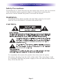
WARNING:
TO REDUCE THE RISK OF FIRE OR ELECTRIC SHOCK, DO NOT
EXPOSE THIS APPLIANCE TO RAIN OR MOISTURE.
CAUTION:
To completely disconnect this product from the main AC power,
disconnect the plug from the wall socket outlet. The main plug is used
to completely interrupt the power supply to the unit and must be within
easy access by the user.
Page 9
DMS-AV HOME THEATER AMPLIFIER
• To prevent the risk of electric shock, do not remove cover. No userserviceable parts inside. Refer servicing to qualified service personnel.
• These servicing instructions are for use by qualified service personnel
only. To reduce the risk of electric shock, do not perform any servicing
other than that contained in the operating instructions unless you are
qualified to do so.
• The ventilation should not be impeded by covering the ventilation
openings with items, such as newspapers, tablecloths, curtains, etc.
• No naked flame source, such as lighted candles, should be placed on the
unit.
• Observe and follow local regulations regarding battery disposal.
• Do not expose the unit to dripping or splashing fluids, do not place
objects filled with liquids, such as vases, on the unit.
• Prevent damage to the power cord. Replace the power cord if it becomes
damaged in any way. Always grasp the plug on the power cord when
plugging or unplugging the receiver from the AC outlet.
• Your system may produce sound levels capable of causing permanent
hearing loss. Do not operate for extended periods of time at high volume
levels
• Protect the receiver from impact and place the receiver on a level surface.
• The receiver is equipped with raised feet to provide ventilation, reduce
acoustic feedback, and protect against scratching the surface the unit is
resting on. URC advises against removing the feet.
• Do not stack anything on top of the receiver (processor, source, etc.)
Leave a minimum of 0.3m clearance from above the top of the receiver.
• The receiver should be located away from sources sensitive to heat.
• Do not perform any internal modifications to the receiver.
• Always connect the receiver's power cord to a dedicated AC outlet for
normal operation.
• If young children are present, adult supervision should be provided until
the children are capable of following all rules for safe operation.
• Mistaking CONTROL OUTPUT or IR INPUT connectors for audio/video
inputs or outputs may damage your receiver or other components.
Page 10
DMS-AV HOME THEATER AMPLIFIER
• It is recommended that the system speaker impedance seen by the
amplifier channels of the receiver not fall below 4 ohms. Best amplifier
thermal stability is achieved when it operates into a 4 ohms or greater
speaker load. The nominal impedance of most home speakers range
between 6 and 8 ohms.
The receiver should be serviced by qualified personnel when:
A. The receiver is not functioning properly.
B. Objects have entered the chassis.
C. The receiver was exposed to rain or any other type of moisture.
D. The receiver was dropped, or the chassis is damaged.
• Any changes or modifications in construction of this device which are
not expressly approved by the party responsible for compliance could
void the user`s authority to operate the equipment.
This Class B digital apparatus complies with Canadian ICES-003 Cet
apprareil numerique de la Classe B est conforme a la norme NMB-003 du
Canada.
Note: The manufacturer is not responsible for any Radio or TV interference
caused by unauthorized modifications to this equipment. Such modifications
could void the user`s authority to operate the equipment.
Manufactured under license from Dolby Laboratories. Dolby, Pro Logic
and the double-D symbol are trademarks of Dolby Laboratories.
Manufactured under license under U.S. Patent Nos: 5,956,674; 5,974,380;
6, 226,616; 6,487,535; 7,212,872; 7,333,929; 7,392,195; 7,272,567 &
other U.S. and worldwide patents issued & pending. DTS-HD, the Symbol,
& DTS-HD and the Symbol together are registered trademarks & DTS-HD
Master Audio is a trademark of DTS, Inc. Product includes software. ©
DTS, Inc. All Rights Reserved.
"HDMI, the HDMI Logo, and High-Definition Multimedia Interface are
trademarks or registered trademarks of HDMI Licensing LLC in the United
States and other countries."
Page 11
DMS-AV HOME THEATER AMPLIFIER
FCC INFORMATION
This equipment has been tested and found to comply with the limits for a
Class B digital device, pursuant to Part 15 of the FCC Rules. These limits
are designed to provide reasonable protection against harmful interference
in a residential installation. If this equipment does cause harmful
interference to radio or television reception, which can be determined by
turning the equipment Off and On, the user is encouraged to try to correct
the interference by one or more of the following measures:
• Reorient or relocate the receiving antenna.
• Increase the separation between the equipment and receiver.
• Connect the equipment into an outlet on a circuit different from that to
which the receiver is connected.
• Consult the dealer or an experienced radio/TV technician for help.
Product name: Home Theater Amplifier
Model Number: TSP-2000E
Responsible Party Name: UNIVERSAL REMOTE CONTROL, INC.
Address: 500 Mamaroneck Avenue, Harrison, NY 10528
Phone: (914)835-4484, Fax: (914)835-4532
URL: www.universalremote.com
Introduction / Overview
URC's DMS-AV is our new state-of-the-art Network Home Theater
Processor which is the centerpiece of your Home Theater System, all based
on network technology. It is easy to setup and use, sounds great and
delivers crystal clear high-definition video to your home theater. The DMSAV provides today's cutting edge technologies and performance with
sophistication and convenience that is unparalleled in this industry, all at
the touch of a button. Dolby Digital, DTS, and URC’s proprietary
multichannel stereo and surround modes deliver the best audio formats to
you with detail, clarity, and tremendous bass and treble response.
URC’s DMS-AV performance is based upon combining our in-house design
expertise with that of our engineering partners. The DMS-AV has a fully
loaded rear panel with 11 discrete audio & video inputs, as well as a
Phono Input (MM), including 5 HDMI Inputs and 7 x 125 watt amplifier
channels. Combine all these connections with our state-of-the-art
technology inside the DMS-AV and you get pristine sound and
picture quality unprecedented in the industry.
Cutting edge technologies combined with URC’s legendary user interface
design, engineering and manufacturing expertise make the DMS-AV the
elegant and easy choice for today’s demanding home theater installations.
Page 12
DMS-AV HOME THEATER AMPLIFIER
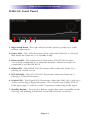
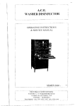
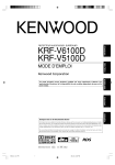
DMS-AV Front Panel
1
2
3
4
5
7
6
1. Right Hand Knob -The right selector knob’s primary purpose is audio
volume adjustment.
2. Power LED – This LED illuminates Blue when the DMS-AV is ON and
Red when the DMS-AV is in Standby mode.
3. Ethernet LED - The Ethernet LED illuminates STEADY BLUE when
successfully connected to an Ethernet network, otherwise when not
connected it will BLINK BLUE.
4. HDMI LED - The HDMI LED illuminates Blue when the DMS-AV is
playing an HDMI source.
5. DTS-HD LED - The DTS-HD LED illuminates when the DMS-AV is
playing a DTS-HD bitstream.
6. Digital LED - The Digital LED illuminates when the DMS-AV is playing a
source containing a digital bitstream. This includes any Dolby, DTS or
PCM input type, as well as a URC Proprietary Streaming Audio Input.
7. Standby Button – Pressing this button toggles the state of Standby mode.
Pressing and holding this button causes the DMS-AV to reboot.
Page 13
DMS-AV HOME THEATER AMPLIFIER
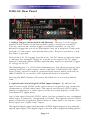
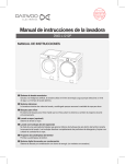
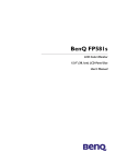
DMS-AV Rear Panel
2
1
3
4
5
678
9 10
11
12
13
1. Voltage Triggers, Reset Switch and Ethernet - The two 12 volt triggers
present at this section of the back panel supply a maximum current of
100 mA, and can be used to trigger an external amplifier, or can also
beused to trigger the use of an anamorphic lens on a projector. These jacks
are both 3.5 mm mono style female mini jacks. The pin is positive(+), and
the sleeve is ground.
Each of the 12V DC triggers may be set to 12V DC when a particular input
is selected. For example, Trigger #1 may be set to output 12V DC when
Input 8 is selected. When another input besides Input 8 is selected, Trigger
#1 will go to 0V DC.
The Ethernet port is a 10/100 Base Ethernet port, that allows receiving and
sending multicast audio streams when used with a DMS/SNP URC Multi
zone system, and also used for command and control when used with an
MRX-10/MRX-12 (or similar) URC Advanced System Controller.
Pressing the RESET button will return the DMS-AV to its factory default
state.
2. Optical and Coaxial Digital S/PDIF Inputs/Output - By default, the
optical and coaxial S/PDIF audio inputs are not assigned to any composite,
component or HDMI video input. The optical and coaxial S/PDIF inputs
require assignment to a video input (via the on-screen display, or the URC
Accelerator PC application).
Any of the optical/coaxial S/PDIF inputs can be assigned to any numbered
video input (Composite, Component or HDMI). The optical/coaxial S/PDIF
inputs cannot be assigned to Input Phono or Input Multi Cast Stream, since
those inputs are “Audio Only” inputs.
The optical digital output shall provide a S/PDIF digital output of any selected
optical input signal. This digital output is for use with a digital recording device.
Page 14
DMS-AV HOME THEATER AMPLIFIER
3. Remote Infrared Input - The Infrared Input port allows for easy integration with
an RF(radio frequency) to IR (infrared) style base station, such as the URC MRF-350
or MRF-260. This port provides the ability to perform simple one-way control of
the DMS-AV with a URC legacy-style infrared remote control, such as a MX-900,
MX-980 or MX-880, among others. Use of this port with RF based remote controls
allows for “stand alone” operation of the DMS-AV, that is, use of the DMS-AV
without an MRX-10/MRX-12 or similar external URC Advanced System Controller.
This is a 3.5 mm mono style female mini jack input, with the tip being positive(+),
and the sleeve being ground.
4. HDMI Inputs/Output - The DMS-AV supports six HDMI connections; five are
used for signal input, while one supports HDMI signal output.
The DMS-AV supports a single HDMI video output. All video signals sent to the
DMS-AV via composite, component, HDMI, or generated by the internal on-screen
display output via the HDMI OUT connector.
The HDMI Technology within the DMS-AV supports all versions of HDMI, which
means it is compatible with the following formats:
sRGB
YCbCr
Blu-ray Disc and HD DVD Video and Audio at Full Resolutionn
Consumer Electronic Control (CEC)
Deep Color
xvYCC
Auto Lip-Sync
Dolby TrueHD Bitstream Capable
DTS-HD Master Audio Bitstream Capable
Audio Return Channel
3D over HDMI
5. Main AC Rocker Style Switch - Provided is a Main AC Rocker Switch. This
switch is sometimes known as a “Vacation” switch, and is used to remove main
AC from the DMS-AV, or perform a hard reboot of the unit.
6. Composite Video Inputs - The DMS-AV supports four composite video RCA
connectors. All video present at these connectors is upconverted to the HDMI
Video Output.
7. Analog Audio Inputs - The DMS-AV provides seven total analog audio inputs.
Six of these inputs support a line-level analog audio signal. One of these inputs
will support a phono level analog audio signal. The Phono Input supports the MM
(Moving Magnet) phono input type. The Phono Input also provides a ground lug
connector on the DMS-AV back panel.
Page 15
DMS-AV HOME THEATER AMPLIFIER
8. Component Video Inputs/Output - The DMS-AV has three component video
connections. Two of these connections are inputs, while the third connection acts
as a video output (in case HDMI is not used).
The component video inputs accept a maximum input resolution of 1080i/60Hz.
The component video output supports a maximum output resolution of
1080i/60Hz. Composite and HDMI video are not converted and will not output via
the component video. The on-screen display is not viewable via the component
video output as it only works with HDMI.
9. Setup Microphone Input - This jack allows the connection of an external
microphone for automated setup of the DMS-AV speakers, in regards to
crossovers, audio levels, and equalization. This is a 3.5 mm mono style female
mini jack, tip being positive(+), and sleeve being ground. A setup microphone is
provided.
10. Record Output – This output is an analog left/right line level signal of the
currently selected analog audio input. Only analog audio input signals are output
via this connection. Volume control settings do not effect the record output. This
stereo pair of analog RCA outputs are for use with an analog recording device.
11. Preamplifier Outputs – The DMS-AV supports nine preamplifier audio
outputs. In addition to the standard “7.1” audio outputs, including front, center,
surround and subwoofer channels, the DMS-AV shall also support a second
subwoofer output channel. These surround outputs are designed for driving
external power amplifiers or powered speakers.
12. Speaker Outputs - The DMS-AV provides seven amplifier channels for
surround sound reproduction, rated at 125 watts per channel into an 8 ohm
speaker load
Within the on-screen display or the URC Accelerator Application, set your DMSAV to use "Surround Back" amplifier channels or "Front Height" amplifier
channels. Surround back speakers and front height speakers cannot be
powered simultaneously.
The output connectors are industry standard high-current binding posts.
Bare speaker wire may be secured within the screw-type binding posts, or
banana plugs may be inserted into the center of the binding posts.
The processed audio present at the binding post connectors (speaker
connections) contains the same processing as the audio present at the preamplifier stage. As an example, if a crossover is applied to the front left and
right preamplifier channels, the same crossover settings are applied to the
front left and right speaker outputs, only amplified.
13. AC Receptacle - For attaching the supplied high current AC power cord
to the unit.
Page 16
DMS-AV HOME THEATER AMPLIFIER
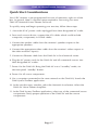
Quick Start Considerations
Your URC receiver is pre-programmed for ease of operation, right out of the
box. In general, there is minimal setup required to start using your new
DMS-AV Network Home Theater Processor.
To quickly setup and begin operating your receiver, follow these steps:
1. Start with all AC power cords unplugged from their designated AC outlet.
2. From each source device, connect the A/V cables which could include
composite, component, or HDMI cables.
3. Connect the speaker cables from the receiver’s speaker outputs to the
appropriate speakers.
4. Connect the appropriate video cables from the receiver’s video outputs to
the video monitor’s input(s).
5. Connect an Ethernet cable from the DMS-AV to local network router.
6. Plug the AC power cords for the DMS-AV and all connected sources into
their designated AC outlets.
7. Power On the DMS-AV. Bring the DMS-AV out of “standby” mode, via
the front panel “standby” button.
8. Power On all source components.
9. On a computer connected to the same network as the DMS-AV, launch the
DMS System Toolbox application.
10. In the unit discovery window, select the Network Scan button. Select the
DMS-AV Home Theater Amplifier.
11. In the DMS System Toolbox application, select any of the connected source
components. Verify proper operation of the DMS-AV and the source
components.
Page 17
DMS-AV HOME THEATER AMPLIFIER
The rest of this manual will give further insight into the many aspects of your
new receiver. Some additional installation considerations should be noted as
follows:
• It is important that your electronic equipment be located where there is
proper ventilation. Failure to ventilate your receiver could result in erratic
operation and possible failure caused by overheating. A minimum of 0.3m
should be maintained above the receiver. Do not place items directly on top
of the receiver. Do not place flammable items on, around or near the A/V
equipment (curtains, paper, etc.).
• URC provides a software program, URC Accelerator, that aids in the setup
process of the DMS-AV. Contact your URC Representative to acquire this PC
Application. URC Accelerator is easy to use and is intended to simplify the
setup process of your new URC Network Home Theater Processor and all
user interfaces.
• Configure a system diagram of all components that are to be connected into
the system. The receiver has a total of eleven Audio and Video inputs, and 1
Phono input. The back panel is labeled IN 1, IN 2, IN 3, IN 4, IN 5, IN 6,
Phono, IN 7, IN 8, IN 9, IN 10, IN 11 for component video /analog audio
sources, Phono for the phono source, and HDMI sources.
The optical digital and coax digital inputs are labeled IN A, IN B, IN C and
IN D respectively, and can be assigned to any of the composite, component
and HDMI Video inputs. By default, the optical and coax digital inputs are not
assigned to any video input. Use the on-screen display or the URC Accelerator
application to assign an optical or coax digital input to any video input.
The source names by default are set to IN 1, IN 2, IN 3 etc...The inputs may be
renamed in the on-screen display, or in the URC Accelerator application to
reflect the desired source name. For example, the name IN 9 may be changed
to “Blu-Ray. The renamed source input name will appear on the DMS-AV’s OSD
(on-screen display).
Page 18
DMS-AV HOME THEATER AMPLIFIER
• Determine the type of cable that is needed for each connection. Keep in
mind that the quality of the cabling that is used may make a difference in the
overall audio and video quality. Try to keep interconnecting cable runs as
short as possible. When routing cables between equipment, be sure to keep
AC cables separate from audio cables. It is a good idea to bundle like cables
together to keep interference (noise) to a minimum.
• It is a good idea to label each cable with a name or number at both ends,
when allocating each cable. Have all the cables you need before you begin
the installation because it is inconvenient to run to the store when you are
excited to hear what the system will sound like.
• Plan enough cable length and space to allow future access to the back panel.
• For best performance it is recommended that a dedicated AC power line or
supply be used. If the equipment is installed in a rack, be sure to insulate the
equipment from the rack itself.
Page 19
DMS-AV HOME THEATER AMPLIFIER
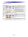
Connection Overview
Audio Connections
Cable
Description
Jack
HDMI
HDMI Connections can carry uncompressed standard or
High Definition digital video and audio. It offers the best
picture and sound quality.
Optical
Digital
Audio
This offers the best sound quality and allows a Dolby
Digital and DTS signal to be sent. The audio quality
is the same as for coaxial.
Coaxial
Digital
Audio
This offers the best sound quality and allows a Dolby
digital and DTS signal to be sent. The audio quality
is the same as for optical. The “orange” RCA
connector represents the digital coax connection.
Analog
Audio
This cable carries analog audio. It is the most common
connection format for analog audio and can be found on
almost all AV components, The “white” RCA connector
represents the left analog audio input and the “red” is
the right.
Video Connections
Cable
Description
Jack
HDMI is an audio and video interface that carries an uncompressed
HDMI
digital bitstream. It can also carry HD video and up to 8 channels of
uncompressed audio.
Component
Component video is analog video information that is separated into three
different signals.
Composite
Composite video is the standard for color video. It combines the
luminance (brightness or black-and-white) and chrominace (color)
information onto a single conductor.
Page 20
DMS-AV HOME THEATER AMPLIFIER
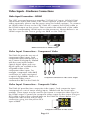
Video Inputs - Hardware Connections
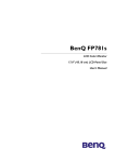
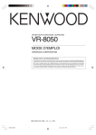
Video Input Connection – HDMI
The URC surround processor provides 5 HDMI A/V inputs. While HDMI
carries both audio and video, URC allows options to process audio and
video separately (please see the menu setup for further options). To connect
an HDMI video source to the URC DMS AV, connect the HDMI cable to
the HDMI output on the source. Then connect the other end of the cable
into the corresponding HDMI input on the processor. Shown below is an
HDMI output on the source going into IN 9 on the DMS-AV.
HDMI connection to HDMI source
Video Input Connection - Component Video
The DMS-AV provides two sets of
component video inputs. Each
component inputcorresponds to a
set of stereo analoginputs, labeled
with the same input number.
Optical digital inputs and coax
digital inputs are available to be
assignedto either of the
component video inputs. For
example, component video IN 5
could have it’s audio reassigned
to optical digital IN A. Shown is a
component video source
connected to IN 5 on the DMS-AV.
Component connection to video source output
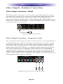
Video Input Connection - Composite Video
The DMS-AV provides four composite video inputs. Each composite input
corresponds to a set of stereo analog inputs, labeled with the same input
number. These inputs may be used to up-convert a composite video signal to
the HDMI output. Connect the composite video output on the source using an
RCA cable to the yellow colored input on the DMS-AV. Shown below is a
composite video source with an RCA
connection going into the yellow RCA
input of IN 1.
Composite connection to video source
Page 21
DMS-AV HOME THEATER AMPLIFIER
Video Outputs - Hardware Connections
Video Output Connection - HDMI
The HDMI output connection on the receiver carries high-definition video to
your television or monitor. To connect an HDMI video output from the DMSAV, connect the HDMI cable to the HDMI output on the DMS-AV. Then
connect the other end of the cable into the corresponding HDMI input on your
television or monitor. Shown below is the HDMI output on the DMS-AV going
to the HDMI input on a monitor.
HDMI input connection to monitor
Video Output Connection - Component Video
The component video output connection on the receiver carries high-definition
or standard definition component video to your television or monitor. HDMI
video and composite video are not routed to the component video output of
the DMS-AV. On-screen display is not viewable from the component video
output of the DMS-AV. To connect a component video output from the DMSAV, connect the three RCA component video cables to the corresponding
component video outputs on the DMS-AV. Then connect the other ends of the
cables into the corresponding component video inputs on your television or
monitor. Shown below is the component video output on the DMS-AV going to
the component video input on a monitor.
Component output connection to input of monitor
Page 22
DMS-AV HOME THEATER AMPLIFIER
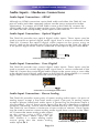
Audio Inputs - Hardware Connections
Audio Input Connection – HDMI
Although an HDMI connection carries both audio and video, the DMS-AV can
process audio and video separately (please see the menu structure for further
information). To connect an HDMI audio source to the DMS-AV, connect the
HDMI cable to the HDMI output on the source. Then connect the other end of
the cable into the corresponding HDMI input on the DMS-AV.
Audio Input Connection - Optical Digital
The DMS-AV provides two optical digital audio inputs. These inputs may be
used to receive an optical digital audio signal from a source connected to the
DMS-AV. Connect the optical digital audio output on the source using an
optical cable to the desired optical digital audio input on the DMS-AV. Shown
is an optical digital audio source connected to the optical digital audio IN A.
Connection to optical dig
audio source
Connection to optical digital audio source
Audio Input Connection - Coax Digital
The DMS-AV provides two coaxial digital audio inputs. These inputs may be
used to receive an coaxial digital audio signal from a source connected to the
DMS-AV. Connect the coaxial digital audio output on the source using a coax cable
to the desired coaxial digital audio input on the DMS-AV. Shown below is a coaxial
digital audio source connected to the coaxial digital audio IN C.
Connection to
coaxial digital audio source
Connection to coaxial digital audio source
Audio Input Connection - Stereo Analog
The DMS-AV provides seven pairs of stereo analog audio inputs. Six pairs of
analog inputs accept a line level audio signal. One pair of analog inputs
accepts a phono (MM) level audio input. A ground lug for the phono input is
also provided. Any of these seven inputs may be set to become a network
multicast “streaming” source, that can be shared with any URC DMS Amplifier.
The DMS-AV can create a maximum of two multicast streams. These inputs
may be used to receive a stereo analog audio signal from a source to the DMSAV. Connect the stereo analog audio output
on the source using a RCA cable to
the analog stereo audio input on the
URC. Shown is a stereo analog audio
source going into the stereo analog
Connection to analog signal source
audio inputt IN 1.
Page 23
DMS-AV HOME THEATER AMPLIFIER
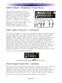
Audio Output - Hardware Connections
Your DMS-AV receiver has both
unbalanced line level RCA surround
output (for use with other external
amplifiers) and speaker binding posts
(for use with the 125 watt internal
amplifiers). These will connect
directly to a speaker or an amplifier.
When connecting audio cables to the
amplifier, be sure to match the
labeled output channels to the
position of the speaker in the room.
Speaker outputs connection to speakers
Audio Output Connection – Unbalanced
The DMS-AV supports 7.1 RCA surround outputs. The preamplifier outputs
can be configured to use either Surround Back speakers or Front Height
speakers. Typical usage of these outputs is for use with other external
amplifiers. These outputs may be used to connect external amplifiers and/or
subwoofer(s) to the DMS-AV. Be sure to match the appropriate preamp
output to the speakers location in the room. For example, connect the
Center Channel output to the center speaker amplifier channel. For use in a
five channel audio system, do not connect the Surround Back or Front
Height audio channels. For use in a six channel audio system, connect the
sixth channel to the Surround Back Left channel. Shown are the DMS-AV
unbalanced outputs connected using standard RCA cables to the
unbalanced inputs on an external amplifier. The Subwoofer output is used
as a line source to a powered subwoofer.
Analog audio unbalanced signal outputs connection to amplifier
Audio Output Connection – Speakers
The DMS-AV powers seven discrete speaker channels. Be sure to match the
appropriate speaker output to the speakers location in the room. For
example, connect the Center Channel output the center speaker amplifier
channel. If a five channel audio system is desired, do not connect the
Surround Back audio channels. If a six channel audio system is desired,
connect the sixth channel to the Surround Back Left channel.
Page 24
DMS-AV HOME THEATER AMPLIFIER
Audio Output Connection – Subwoofer(s)
The DMS-AV supplies two subwoofer (.2) outputs. Connect the subwoofer
output(s) to the input on the subwoofer(s). The diagram shows how the receiver
may be connected to active subwoofer(s).
Subwoofer outputs connection to
subwoofers powered amplifer
Audio Output Connection - Optical Digital Record
The optical digital output will output the S/PDIF optical digital signal of the
source selected on the receiver. If you wish to record both analog and digital
sources you must connect both analog and digital outputs to your recorder. The
DMS-AV does not convert digital audio to analog audio nor does it convert
analog audio digital audio.
Audio Output Connection - Analog Record
A stereo pair of analog RCA outputs for use with an analog recording device. If
you wish to record both analog and digital sources you must connect bot
hanalog and digital outputs to your recorder. The DMS-AV does not convert
digital audio signals to analog audio recording signals, and does not convert
analog audio signals to digital audio recording signals. The DMS-AV does not
convert digital audio to analog audio nor does it convert analog audio digital
audio.
Page 25
DMS-AV HOME THEATER AMPLIFIER
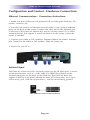
Configuration and Control - Hardware Connections
Ethernet Communication - Connection Instructions
1. Make sure that all devices are powered Off, including the DMS-AV, PCs,
routers, switches, etc.
2. Connect one end of an Ethernet network cable to one of the numbered
ports on the back of the router. Connect the other end to the Ethernet port
in the rear of the DMS-AV. Repeat this step to connect more PCs or other
network devices that require a wired connection to the router. Power the
router as needed.
3. Connect your cable or DSL modem’s Ethernet cable to the router’s Internet
port. Power On the cable or DSL modem, DMS-AV, router, etc.
4. Power On your PC(s).
Infrared Input
The DMS-AV allows for basic infrared control via the IR Input port. Connect
an Infrared receiver, such as a URC MRF-350 IR/RF Base Station to the
infrared input port on the back of the DMS-AV. The DMS-AV does not
support a built-in front panel infrared receiver. All connections are 3.5mm
(mono mini) jack, with the tip positive(+), and the sleeve being ground.
MRF-350 RF Base Station to DMS-AV IR Input
Page 26
DMS-AV HOME THEATER AMPLIFIER
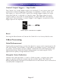
Control Output Triggers / Amp Enable
The Control Out / Amp Enable outputs are standard 3.5 mm (mono mini) jack
connections used for triggering such pieces as amplifiers, screens, relays, etc.
The output is a 100 mA 12 VDC signal. The voltage trigger outputs are active
when the DMS-AV is selected to a specific input. The trigger input for each
control output is set in the on-screen display, or within the URC Accelerator
application. Shown below is control Trigger 1 and Trigger 2 connection to the
trigger input on an amplifier.
Control output 1 connection to an amplifier
Reset
Pressing the Reset button will return the DMS-AV to its factory default state.
Video Processing
Detail Enhancement
Detail enhancement brings out the fine detail in scenes and is important for SD
and HD material. For example, it’s possible to see blades of grass, small details
on jackets, and wrinkles on faces. When combined with Noise Reduction and
Advanced Scaling, DMS-AV Detail Enhancement can make regular DVDs
approach the quality of high-definition DVDs.
Mosquito Noise Reduction
Satellite and cable providers, as well as DVR recorders, compress the video
signal to get the maximum content into the smallest space. The DMS-AV
delivers high-quality Mosquito Noise Reduction to remove the noise and artifacts
caused by this compression.
Page 27
DMS-AV HOME THEATER AMPLIFIER
Edge Enhancement
Edge Enhancement brings out the fine detail in the edges of objects, and is
important for SD and HD material. When combined with Noise Reduction and
Advanced Scaling, DMS-AV Edge Enhancement can make regular DVDs
approach the quality of high definition DVDs.
HDMI Audio Output
The HDMI output of the DMS-AV has the ability send the processed audio to
the display monitor, bypassing the preamp section and speaker outputs. In the
HDMI Setup menu within the on-screen display and the URC Accelerator
application, set the HDMI Audio Output to “Passthrough” to enable this option.
CEC Control
The DMS-AV has the ability to execute Consumer Electronics Control (CEC) to a
monitor or projector that is connected by HDMI, and is CEC Capable.
Consumer Electronics Control (CEC) is a feature designed to allow the user to
command and control two or more CEC-enabled boxes, that are connected
through HDMI, by using only one of their remote controls. (i.e. controlling a
television set, set-top box and DVD player using only the remote control of the
TV). CEC also allows for individual CEC-enabled devices to command and
control each other without user intervention.
CEC options for the DMS-AV are the following:
• On (Power On)
• On (Always)
• Off
The default CEC setting for the DMS-AV is Off.
Consult your individual display monitor or projector manual for specific
information regarding their CEC compatibility.
Auto A/V Sync
This feature monitors an incoming HDMI bitstream, and uses information
within the bit stream to automatically correct any audio and video syncing
issues. By default, this option is set to Off.
Page 28
DMS-AV HOME THEATER AMPLIFIER
Video PReP®
Progressive Re-Processing (PReP®) is the industry’s first technology
designed specifically to improve progressive video signals by removing the
artifacts causedby inferior interlaced-to-progressive conversion. Video
signals that originate inthe interlaced format used by most broadcasters
often suffer degradation whenthe signal is converted to the progressive
format required by digital displays. Ifthis process is not done well, it results
in artifacts which will be amplified duringscaling or other processing such
as detail enhancement. The patent-pending PReP technology addresses this
problem be reverting the progressive video signal to its original interlaced
format so that it can be reconverted to progressiveusing a higher-quality
deinterlacer.
The DMS-AV has two available options for PReP – Auto and Off. By default,
PReP is set to Off. This value can be set in the on-screen menu or the URC
Accelerator Application, in the Video Adjust section.
Video Test Patterns
The DMS-AV firmware includes eight video test patterns used to calibrate a
video display device. Typically, an external video test pattern generator is
required for professional display device setup. The DMS-AV provides access
to these patterns within the on-screen display, and also accessible via the
URC Accelerator Application.
The video test patterns available are:
Frame Geometry
‘Frame/Geometry’ test pattern is used to verify that the image is positioned
correctly on your display.
Bright/Contrast
The ‘Brightness/Contrast’ test pattern will assist you in setting up both the
brightness (black level) and contrast (white level) of your display. The
‘Brightness/Contrast’ test pattern is composed of 4 quarter-screen blocks.
Two of the blocks have a background level of standard black and the other
two blocks have a background level of standard white.
Embedded in the black blocks are 3 bars. One is 4 IRE below black
(blacker-than-black), one is 1 IRE above black, and the third is 2 IRE above
black. Embedded in the white blocks are 3 bars. One is 1 IRE above white
(whiter-then-white), one is 1 IRE below white, and the third is 2 IRE below
white. The bottom two blocks differ slightly from these levels. For the
bottom two blocks, the blacker-than-black is at the lowest possible luma level
and the whiter-than-white bar is at the highest possible luma level.
Page 29
DMS-AV HOME THEATER AMPLIFIER
When the brightness and contrast are adjusted correctly, you should be able to
see the 1 IRE and 2 IRE above black bars on the black background and the 1
IRE and 2 IRE below white bars should be visible on the white background.
When the brightness is adjusted correctly, black objects should appear ‘black’
with the details still intact and lighter areas should be ‘light’, not gray, with the
details still intact. When the contrast is adjusted correctly, white objects will
appear ‘white’ with the details still intact. Because the contrast settings can
affect brightness settings we recommend that you check the brightness setting
after making this adjustment.
Checker board
When the Checkerboard test pattern is displayed correctly, close up you should
be able to see a 1- pixel checkerboard and at proper viewing distance the
image should appear as an even gray. If your display is CRT-based you will not
see this checkerboard, but your screen should be an even gray. When this test
pattern is displayed incorrectly, the resulting image does not look like a fine
checkerboard and may have irregular patterns. If this is the case then the
chosen output resolution may not be the native resolution of your display or
your display may scale all input signals even if the input resolution is already at
native resolution. Check to make sure that the output resolution selected on the
DMS-AV is the correct output resolution for your display.
Vertical Lines
The ‘Vertical Lines’ test pattern should appear as one pixel wide black and
white columns. If you see any irregular pattern(s) in the image then you know
that the display is scaling the signal horizontally.
Horizontal Lines
The ‘Horizontal Lines’ test pattern should appear as one pixel tall black and
white rows. If you see any irregular pattern(s) in the image then you know that
the display is scaling the signal vertically.
Judder
The ‘Judder’ test pattern displays a bar that bounces back and forth at the
chosen output resolution. When this test pattern is displayed correctly, the bar
will move smoothly across the screen and bounce from side to side. When this
pattern is displayed incorrectly, this bar may ‘tear’ as it moves across the screen.
Page 30
DMS-AV HOME THEATER AMPLIFIER
Color 8 Bars 75
In this SMPTE color bar image, the displayed pattern contains eight vertical bars
of 75% intensity.
Color 8 Bars 100
In this SMPTE color bar image, the displayed pattern contains eight vertical bars
of 100% intensity.
OSD Transparency
The on-screen display transparency can be set to Low, Medium or High. The
default value for the DMS-AV is Low. This value can be set in the on-screen
display, or the URC Accelerator Application.
Audio Modes and Speaker Selections
The DMS-AV incorporates a state-of-the-art software and hardware system that
allows the end-user to select the appropriate number of speakers, two-channel
surround decoder (Dolby Pro Logic IIx, Dolby Pro Logic IIz or DTS NEO:6) or
multi-channel surround mode (Movie or Music) depending on the user’s
preference. Multi-channel encoded bit streams (DTS and Dolby Digital) are
automatically detected and selected for any digital input.
Audio/Surround Mode Usage
Custom Audio/Surround modes are available for selection with the DMS-AV.
These audio modes are selectable by pressing the Surround Up or Surround
Down button on the remote control:
Theater
Movie
Hall
Game
Stadium
Multi Channel Stereo F.S.S. (Front Stage Surround Effectiveness)
A.L.C. (Auto Volume Level control)
Page 31
DMS-AV HOME THEATER AMPLIFIER
On Screen Display (OSD) Format
The DMS-AV on-screen Display allows for the complete system setup of the
DMS-AV, when using in an application that does not include a URC DMS Multi
Zone Audio System.
Momentary OSD
On-screen display information, such as volume level and input name can be
disabled, if desired. Within the System Setup section of the on-screen display, or
within the URC Accelerator PC Application, set this feature to “Off”, if desired.
Software Setup - URC Accelerator
URC Accelerator is the advanced PC application used to configure the
DMS-AV, the appropriate user interface remote control, and integration with
URC DMS Multi Zone amplifiers. Contact your URC representative to acquire
the URC Accelerator PC Application.
DMS-AV System Settings – Audio
Speaker Size/Speaker Crossover
Speaker size refers to the frequency range a speaker can handle. Audio
material, particularly Dolby Digital and DTS movies, often contain large
amounts of bass. If this bass information is sent to small speakers that are
incapable of reproducing bass, then this information will be lost or distorted.
Too much bass may damage small speakers. By configuring the DMS-AV for the
correct type of speaker crossover, all bass information will be appropriately
routed to the speakers that are best able to reproduce it correctly.
Typically bookshelf or satellite speakers are considered Small. Smaller floor
standing speakers with a single 8” or less woofer should also be considered
Small. Floor standing speakers with 10” or larger woofers, or multiple smaller
woofers may be considered Large. These are general guidelines only if you are
unsure, please consult your speaker manufacturer or dealer.
If using large speakers, the system may not require a subwoofer, however better
results may still be obtained with the use of a subwoofer. Even with speakers
that are capable of reproducing deep bass, better overall bass response may be
obtained by setting a crossover frequency for these speakers. This allows bass to
be reproducedfrom a single point (the subwoofer), and avoids the possibility of
phase cancellationwhich may occur when bass is reproduced from multiple
speakers simultaneously.
Page 32
DMS-AV HOME THEATER AMPLIFIER
Front Speakers
There must be at least 2 front speakers in order to use the DMS-AV. Set the
crossover frequency of the front speakers in the on-screen display or the
URC Accelerator Application, based on the guidelines described above.
Center Speaker
It is not necessary to have a center speaker. Set the Center Speaker Option
in the on-screen display to Yes or No, or set this in the URC Accelerator
Application, based on the center channel availability. If set to NO the
center information will be reproduced in the front left and front right
speakers. No audio information is lost, however the sense of voices coming
from the screen may be lost. Set the crossover frequency of the center
speaker in the on-screen display or the URC Accelerator Application, based
on the guidelines described above.
Surround Speakers
It is not necessary to have surround speakers. Set the Surround Speaker
Option in the on-screen display to Yes or No, or set this in the URC
Accelerator Application, based on the surround channels availability. If
Surround Speaker Option is set to NO, the surround information will be
reproduced in the front left and right speakers. No information is lost but
the sense of spaciousness provided by discrete 5.1 channel sound tracks or
2 channel tracks enhanced by Dolby Pro Logic IIx or DTS Neo:6 may be
lost. If surround speakers are set to No, surround back speakers are not
available.
Surround Back Speakers
It is not necessary to have surround back speakers. Set the Surround
Speaker Option in the on-screen display to Yes or No, or set this in the URC
Accelerator Application, based on the surround channels availability. If the
surround speakers are set to none, no options will appear for the surround
back speakers. There is the option to use 1 or 2 back speakers. If set to
none, the back information will be reproduced in the surround speakers
and although no information is lost, the sense of sounds coming from
directly behind you may be lost. If surround back speakers are used, front
height speakers are not available.
Page 33
DMS-AV HOME THEATER AMPLIFIER
Front Height Speakers
It is not necessary to have front height speakers. Set the Front Height
Option in the on-screen display to Yes or No, or set this in the URC
Accelerator, based on the surround channels availability. If set to none, the
front height speaker information will be reproduced in the front speakers
and although no information is lost, the sense of sounds coming from
directly above you may be lost. If front height speakers are used, surround
back speakers are not available.
Subwoofer(s)
There are four choices for subwoofer. If set to No, all bass information,
including LFE (.1 channel) will be routed to any speakers that are
configured to pass low frequency information, as described in the setup
above. If the individual speaker crossovers are not set to pass low frequency
information, and no subwoofers are used in the system, the low frequency
information shall be lost.
The most common setting for subwoofer is Preout 1/2, which allows for
connections of two subwoofers, taking advantage of the DMS-AV’s ability to
reproduce low frequency information through two subwoofers (.2).
Setting the Subwoofer to Preout 1 shall configure the DMS-AV to send low
frequency information from its Sub 1 preamplifier output only.
Setting the Subwoofer to Preout 2 shall configure the DMS-AV to send low
frequency information from its Sub 2 preamplifier output only.
Speaker Distance
Ideally the speakers should be positioned at an equal distance from the
listening position. However, physical limitations usually require placing the
speakers in other than optimum locations. The DMS-AV contains a means
to electronically move each speaker’s location. This allows for superior
reproduction of the directional cues available during movie or music
playback. Measure the distance in feet from your listening position to each
speaker. Enter this information into DMS-AV’s on-screen display, or into the
URC Accelerator Application. Default measurement units are feet, but units
may be changed to meters if preferred.
Page 34
DMS-AV HOME THEATER AMPLIFIER
Channel Level
Channel level calibration will allow the equalization of the volume levels of
each speaker to make up for differences in speaker characteristics and
distances from the listener to the speakers. Best results will be achieved
using a Sound Pressure Level (SPL) meter, and an external analog tone or
pink noise generator. Set the SPL Meter to C Weighting and Slow Response.
Place the meter at your listening position and adjust each speaker for an
equal response (An SPL of 75 dB is recommended).
Speaker Crossover (X-Over)
This sets the frequency at which bass tones are filtered from the speaker
channel selected and sent to the subwoofer(s). The crossover point is the
frequency at which the amount of information in the subwoofer and main
speaker(s) is equal. Set this according to the capabilities of the speakers
and/or subwoofer(s). When a crossover frequency for a speaker is set, the
crossover frequency and above is sent to the affected speaker, while the
crossover frequency and below is sent to the subwoofer(s).
Each speaker in the system (except for the subwoofer) has a specific
crossover assigned to it. Each speaker has the ability to have a unique
crossover frequency set for it. While the subwoofer does not have its own
unique crossover, the subwoofer low frequency content is determined by
the crossover settings of all other speakers in the system. All low frequency
material below the crossover frequency set point for each speaker is sent to
the subwoofer(s).
LFE (Dolby/DTS)
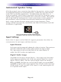
This setting is used to increase or decrease the subwoofer level for
multichannel bitstreams that contain an Low Frequency Effects channel. The
subwoofer signal may need to be increased or decreased depending on the
room or installation. Usually this will be set to 0 dB (default). Note that this
effects only the separate LFE (.1) or subwoofer channel available on source
material. There is no effect on the reproduction of normal bass from the
front, center, or surround channels.
Page 35
DMS-AV HOME THEATER AMPLIFIER
Height Gain
The Height Gain applies to the Front Height speakers. This option is
available when the DMS-AV is set to use Front Height speakers. Three
options are available for this setting: Low, Mid and High. The default value
for this
parameter within the DMS-AV is “Mid”. Change this value within the onscreen display, or in URC Accelerator under the sound adjust section.
Dolby Pro Logic II Music Setup
Three unique parameters are available to “shape” the sound of sources
played through the Dolby Pro Logic II Music mode. The parameters
available are:
Panorama
Panorama wraps the sound from the front left and right speakers
around you, sending an image to the surround speakers for an exciting
perspective.
Center Width
Center width lets you gradually spread the center-channel sound into
the front left and right speakers. At its widest setting, all the sound from
the center is mixed into the left and right speakers.
Dimension
Dimension control adjusts the front/surround balance to suit your
listening preference.
Night Mode
When the Night Mode option is enabled the sound level of compatible
digital audio soundtracks will be dynamically compressed. Dynamic range
compression increases low-level audio content such as dialog, making it
easier to hear at low volume levels while at the same time reducing the
intensity of higher-level audio content.
Dynamic range control (Night Mode) enables you to customize audio
playback to reduce peak volume levels (no loud surprises) while
experiencing all the details in the soundtrack, enabling late-night viewing of
high-energy surround sound without disturbing others.
Available options for night mode are: Auto, Off, Low, Medium and High,
depending on the incoming bitstream type. Adjust this parameter in the
Sound Adjust section of the on-screen display, or the URC Accelerator
Application.
Page 36
DMS-AV HOME THEATER AMPLIFIER
Surround modes
DTS Surround
DTS Surround (also called simply DTS) supports up to 5.1 discrete channels
and uses less compression for high fidelity reproduction. Use it with DVDs
and CDs bearing the DTS logo.
DTS-ESTM Discrete 6.1
This is a 6.1 channel discrete digital audio format adding a surround back
channel to the DTS digital surround sound. The seven totally separate audio
channels provide better spatial imaging and 360 degrees sound
localization, perfect for sounds that pan across the surround channels. Use
it with DVDs bearing the DTS-ES logo, especially those with a DTS ES
Discrete sound track.
DTS-ESTM Matrix 6.1
This is a 6.1 channel discrete digital audio format inserting a surround back
channel to the DTS digital surround sound through matrix encoding. Use it
with DVDs bearing the DTS-ES logo.
DTS-Neo: 6TM Surround
DTS Neo: 6 is a matrix decoding technology for achieving 7.1 channel
surround playback with 2 channel sources. It includes ‘DTS Neo: 6 Music’
suited for playing music.
DTS 96/24
This is high resolution DTS with a 96 kHz sampling rate and 24 bit
resolution, providing superior fidelity. Use it with DVDs bearing the DTS
96/24 logo.
DTS-HD High Resolution Audio
Developed for use with HDTV, including the new video disc formats Bluray and HD DVD, this is the latest multi-channel audio format from DTS. It
supports up to 7.1 channels with 96 kHz/24 bit sampling rate and signal
resolution.
DTS –HD Master Audio
Designed to take full advantage of the additional storage space offered by
the new Blu-ray and HD DVD disc formats, this new DTS format offers up
to 7.1 discrete channels for uncompressed digital audio with 96 kHz/24 bit
sampling rate and signal resolution.
Page 37
DMS-AV HOME THEATER AMPLIFIER
Dolby Digital
Dolby Digital is the multi-channel digital signal format developed by Dolby
Laboratories. Discs bearing the Dolby Digital logo include the recording of
up to 5.1 channels of digital signals. This will put you right in the middle of
the action, just like being in a movie theater or concert hall.
Dolby Digital EX
This mode expands 5.1 channel sources for 6.1/7.1 channel playback. It’s
especially suited to Dolby Digital EX soundtracks that include a matrix encoded
surround back channel. The additional channel adds an extra dimension
and provides an enveloping surround sound experience, perfect for rotating
and fly-by sound effects.
Dolby Digital Plus
Developed for use with HDTV, including the new video disc formats Bluray and HD DVD, this is this latest multichannel audio format form Dolby.
It supports up to 7.1 channel with 48 kHz/24 bit sampling rate and signal
resolution.
Dolby True HD
Designed to take full advantage of the additional storage space offered by
the new Blu-ray and HD DVD disc formats, this new Dolby format offers up
to 7.1 discrete channels of lossless audio performance with 96 kHz/24 bit
sampling rate and signal resolution.
Dolby Pro Logic IIz
This mode adds front height channels to surround sound, creating a 7.1
channel playback for music, movies and video games. Dolby Pro Logic IIz
brings enhanced spatial effects, added depth, and an overall airiness to
listening experience
Dolby Pro Logic IIx
This mode expands any 2-channel source for 7.1 channel playback. It
provides a very natural and seamless surround sound experience that fully
envelopes the listener. As well as music and movies, video games can also
benefit from the dramatic spatial effects and vivid imaging. it includes
‘Dolby Pro Logic IIx Movie’ suited for playing movies, ‘Dolby Pro Logic IIx
Music’ suited for playing music and ‘Dolby Pro Logic IIx Game’ suited for
playing games.
Page 38
DMS-AV HOME THEATER AMPLIFIER
Dolby Pro Logic II
If you are not using any surround back speakers, Dolby Pro Logic II
surround will be used instead of Dolby Pro Logic IIx surround. It includes
Dolby Pro Logic II Movie, Dolby Pro Logic II Music and Dolby Pro Logic II
Game like Dolby Pro Logic IIx surround.
Theater
This mode provides the effect of being in a theater when watching dvd.
Movie
This mode provides the effect of being in a movie theater when watching a
movie.
Hall
This mode provides the ambience of a concert hall for classical music
sources such as orchestral, chamber music or an instrumental solo.
Game
This mode is suitable for video games.
Stadium
This mode provides the expansive sound field to achieve the true stadium
effect when watching sporting events.
Multi Channel Stereo
This mode is designed for playing background music. The front, surround
and surround back channels create a stereo image that encompasses the
entire area.
F.S.S (Front Stage Surround)
This mode allows you to create natural surround sound effects using just the
front and the rear speakers.
Page 39
DMS-AV HOME THEATER AMPLIFIER
A.L.C (Auto Volume Level Control)
This mode automatically equalizes playback sound level if each sound level
varies with the music source recorded in a portable audio player.
Note
u
The sound from each channel can be reproduced according to the
surround modes as follows:
(*) : Depending on the subwoofer setting, the sound from the
subwoofer channel may be reproduced.
u
Depending on the speaker setting and the number of the encoded
channels,etc., the sound from the corresponding channels cannot be
reproduced.
Page 40
DMS-AV HOME THEATER AMPLIFIER
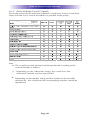
Selecting the Surround mode
Before surround playback, first perform the speaker setup procedure, etc.
on the OSD settings for optimum performance.
Select the desired surround mode by pressing the SURROUND U(•) /
DOWN(•) buttons.
• Each time the buttons are pressed, the surround mode changes
depending on the input signal format as the table below:
Depending on surround back speaker setting, some surround modes can be selected or not as follows
< > : possible only when surround back speaker is not set to “NO”.
[ ] : possible only when surround back speaker is set to “NO”.
( ) : possible only when surround back speaker is set to “2ch”.
{ } : possible only when front height speaker is set to “ON”.
* : stand for THEATER, MOVIE, HALL, GAME, STADIUM, MCH STEREO, F.S.S, A.L.C.
** : on the signal format being input, the Dolby Pro Logic IIx modes may not be selected.
Note
•When “Center” and “Surround” are set to “NO”, any surround mode cannot be selected and the source can
be reproduced in the stereo mode.
•While playing digital signals from Dolby Digital or Dolby TrueHD program source or listening in Dolby Pro
Logic II/Dolby Pro Logic IIx Music mode or Dolby Pro-Logic IIz mode, you can adjust their parameters for
optimum surround effect.
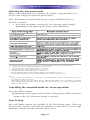
Cancelling the surround mode for stereo operation
Press the STEREO button.
uDepending on the signal format which is being input, either the Stereo
Mode or the 2CH down-mix model is selected.
Tone Setting
Bass and Treble controls are available in the Tone Setting menu. These are
shelving tone controls, and allow the addition or subtraction of low or high
frequency content from the selected audio source.
Page 41
DMS-AV HOME THEATER AMPLIFIER
Automated Speaker Setup
All of the manual room correction described in the previous section can be
accomplished through an automated process, within the on-screen display,
or the URC Accelerator Application. Included with each DMS-AV is a
setup microphone, which when connected to the DMS-AV Setup Mic input,
can be used to perform an automated room correction routine. The internal
DSP of the DMS-AV shall execute a series of test tones to each speaker in
the installation, which will then automatically determine each speaker
level, correct speaker distance setting and crossover frequency. These
settings will be automatically saved within the DMS-AV firmware, and URC
Accelerator, if applicable.
The Set up Microphone included should be the only
microphone used in the automatic setup configuration.
Input Settings
Each of the 12 inputs on the DMS-AV supports parameters that allow for
customization for each input and their function.
Input Rename
Each input may be renamed to better de scribe its function. The maximum
amount of characters that can be used to rename an input is eight.
The input name can be set in the DMS-AV on-screen display, or
within the URC Acceler ator Application.
Digital Audio Assign
(Available for all inputs except Phono) – Each input may have their
audio input reassigned to any of the two optical digital or coaxial
digital (S/PDIF) inputs. The two optical digital inputs are named
IN A and IN B, and the two coaxial digital inputs are named IN C
and IN D. Digital audio assign options may also be used to reassign
HDMI audio, in the case that a DVI input is used, requiring the use
of a separate audio input.
Page 42
DMS-AV HOME THEATER AMPLIFIER
Analog Audio Assign
(Available for HDMI inputs only) - Analog audio assign options may also be
used to reassign HDMI audio to any of the line level analog audio inputs
(IN 1through IN 6).
Video Scaling
This allows setting of a desired output resolution per input selected by the
DMS-AV. All inputs, except phono, support a discrete video output
resolution mode. Also available is an “HDMI Bypass” mode, which is
essentially a mode that transfers the native resolution of the selected source
to the display monitor or projector, via the DMS-AV’s HDMI output.
A/V Sync
This setting allows correction for the native Lip-Sync A/V delay of the
connected video monitor, and the selected source. One video frame
is approximately 17 mS delay. A/V Sync allows for up to 200 mS of
A/V Sync correction. Modern HD monitors may have up to 5 frames
of perceivable delay.
DC Trigger 1
This setting allows DC Trigger 1 to be set to trigger a 12V DC signal
from DC Trigger 1 when a specific input is selected.
DC Trigger 2
This setting allows DC Trigger 2 to be set to trigger a 12V DC signal
from DC Trigger 2 when a specific input is selected.
Linking Audio Zones with the DMS-AV
The DMS-AV has the ability to create multicast audio streams for two
analog audio inputs. These streams can then be sent to URC DMS multi
zone amplifiers for the purpose of creating secondary audio zones with
sources that are connected to the DMS-AV. Please contact your URC
representative for more information regarding sharing analog sources with
other URC DMS multi zone amplifiers.
Page 43
DMS-AV HOME THEATER AMPLIFIER
Accessing Streaming Audio Sources with the DMS-AV
The DMS-AV has the ability to receive multicast audio streams from URC
DMS multi zone amplifiers and SNP units in a Total Control project. Up to
32 audio multicast streaming sources can be selected by the DMS-AV. Please
contact your URC representative for more information regarding accessing
multicast sources from other URC DMS multi zone amplifiers.
Updating DMS-AV Firmware
The DMS-AV firmware can be updated via the URC Accelerator
Application. Contact your URC representative about available firmware
updates for the DMS-AV.
DMS-AV Specifications
General Information
Video Scaler: ABT 2015 with Graphic OSD
Network Control & Music streaming (with URC DMS Amplifiers)
TI Room EQ
HD Audio 7.2ch/HDMI (3D, ARC)
12V DC Trigger Out: 2 (assignable)
Standby Power Management: Under 0.5W
CE Lot 6 / Energy Star version 2
Power Supply: AC 230V 50Hz
AC Cord Type: Detachable
Power Amplifier
Type: Analog Discrete 7 channel Power Output: 125 Watts per channel
(20~20kHz/8 ohms/0.05%)
Power Transformer: E type
Wide Range Amplifier Stage: Yes (10~100kHz)
Page 44
DMS-AV HOME THEATER AMPLIFIER
DSP Processing
Processor: TI DA 788
D/A Converter: 192KHz / 24Bit for All channels
Auto Speaker Setup: Yes
Room EQ: TI
Decoding/Surround DTS-HD MA / HRA: Yes
DTS ES: Yes
DTS: Yes
DTS 96/24: Yes
DTS Neo:6: Yes
Dolby TrueHD / Digital Plus: Yes
Dolby Digital EX: Yes
Dolby Digital: Yes
Dolby ProLogic IIx: Yes
Dolby ProLogic IIz: Yes
Surround Format Auto Detection: Yes
AV Sync: Yes (more than 150 ms)
User-selectable Crossover: 40~250Hz
Video Processing
Processor: ABT 2015
Video Conversion Analog to HDMI: Yes
Video Scaling: HDMI to HDMI: 1080p maximum
Analog to HDMI: 1080p maximum
Video Capability: 1080p 60Hz, 1080p 24Hz with full on-screen display
HDMI (3D/ARC/CEC)
Video Input/Output
Component Video Inputs: 2
Component Video Output: 1
Composite Video Inputs: 4
HDMI A/V Inputs: 5
HDMI A/V Output: 1
Page 45
DMS-AV HOME THEATER AMPLIFIER
General Audio Features
Preamplifier Outputs: Front / Center / Surround / Surround Back / Front
Height Subwoofer (2)
Speaker Outputs: Front / Center / Surround / Surround Back / Front Height
(assignable)
AMP Assign for Multi-Speaker: Yes
Speaker Output Terminals: Binding Post
Digital Audio Inputs: 2 Optical S/PDIF, 2 Coaxial S/PDIF
Analog Audio Inputs: 6 Line Level Inputs, 1 Phono Level Input
Page 46
DMS-AV HOME THEATER AMPLIFIER
Limited Warranty Statement
1. Limited Warranty and Disclaimers
Universal Remote Control, Inc. (“URC”) warrants that the URC equipment
shall be free from defects in material and workmanship under normal usage for
one (1) year from purchase when such is purchased from URC. This limited
warranty is valid only in the United States of America. URC warrants that the
software will substantially conform in any material respect to its functional
specifications at the time of delivery. URC SHALL NOT BE LIABLE FOR
OPERATIONAL, TECHNICAL OR EDITORIAL ERRORS AND/OR
OMISSIONS MADE IN THE URC DOCUMENTATION. URC DOES NOT
WARRANT THAT THE URC SOFTWARE IS BUG-FREE OR ERROR FREE OR
THAT THERE ARE NO ERRORS/BUGS IN THE URC SOFTWARE.
URC warrants that at the time of purchase the URC equipment and the URC
software complied with all applicable regulations and policies of the Federal
Communications Commissions (“FCC”) regarding electromagnetic interference
caused by electronic/computing devices and to the extent that the URC
equipment and/or the URC software fails to so comply, URC shall, at its own
expense, take all reasonable measures to promptly cause such to comply.
URC equipment purchases from other than an authorized URC dealer or
distributor are without warranty.
THIS LIMITED WARRANT DOES NOT COVER TECHNICAL ASSISTANCE
FOR HARDWARE OR SOFTWARE USAGE EXCEPT AS EXPRESSLY
PROVIDED FOR HEREIN, THE EQUIPMENT, SOFTWARE AND
DOCUMENTATION OF URC ARE SUPPLIED “AS IS” WITHOUT ANY
WARRANTY, EXPRESS, STATUTORY OR IMPLIED, OF ANY KIND. TO
THE MAXIMUM EXTENT PERMITTED BY APPLICABLE LAW, URC
EXPRESSLY DISCLAIMS ALL WARRANTIES, EXPRESS, STATUTORY OR
IMPLIED, INCLUDING BUT NOT LIMITED TO THE WARRANTIES OF
MERCHANTABILITY AND FITNESS FOR A PARTICULAR PURPOSE. URC
DOES NOT WARRANT, GUARANTEE, OR MAKE ANY
REPRESENTATIONS REGARDING THE USE OF, OR THE RESULTS OF THE
USE OF, THE EQUIPMENT, SOFTWARE OR DOCUMENTATION IN
TERMS OF CORRECTNESS, ACCURACY, RELIABILITY OR OTHERWISE.
EXCEPT AS EXPRESSLY PROVIDED FOR HEREIN, TECHNICAL SERVICES
ARE SUPPLIED “AS IS”, WITHOUT ANY WARRANTY, EXPRESS,
STATUTORY OR IMPLIED, OF ANY KIND. TO THE MAXIMUM EXTENT
PERMITTED BY APPLICABLE LAW, URC EXPRESSLY DISCLAIMS ALL
WARRANTIES, EXPRESS, STATUTORY OR IMPLIED, INCLUDING BUT
NOT LIMITED TO THE WARRANTIES OF QUALITY OR REASONABLE
SKILL AND CARE, OR OUTCOME OR WITHOUT IN ANY WAY LIMITING
Page 47
DMS-AV HOME THEATER AMPLIFIER
THE GENERALITY OF THE OTHER PROVISIONS HEREIN, WARRANTY
DOES NOT COVER: (I) DAMAGE FROM MISUSE, NEGLECT OR ACTS OR
NATURE, (II) MODIFICATIONS, (III) INTEGRATION WITH THIRD PARTY
CONTENT (IV) BEYOND THE WARRANTY PERIOD AND/ OR FAILURE TO
FOLLOW URC WARRANTY CLAIM PROCEDURE.
The warranty limitations and warranty disclaimers may not apply to end user
in whole or in part, where such are restricted or excluded by applicable law
and such shall apply to the maximum extent permitted by applicable law.
In the event of any warranty claim, URC will, at its sole option, repair the URC
equipment using new or comparable rebuilt parts, or exchange the URC
equipment for new or rebuilt equipment. In the event of a defect, these are
the end user’s exclusive remedies.
All the URC equipment returned for service, exchange or repair require an
RGA number. To obtain an RGA number, you must complete a Return
Request Form which you may obtain by calling (914) 835-4484 or contacting
URC at [email protected]. To obtain warranty service, end
user must deliver the URC equipment, freight prepaid, in its original packaging
or packaging affording adequate protection to URC at 420 Columbus Avenue,
Valhalla, NY 10595. It is end user’s responsibility to backup any macro
programming, artwork, software or other materials that may have been
programmed into the unit. It is likely that such data, software, or other materials
will be lost during service and URC will not be responsible for any such
damage or loss. A dated purchase receipt, bill of sale, installation contract or
other verifiable proof of purchase is required. For the URC equipment support
and other important information, please visit URC's website available at
www.universalremote.com or call the Customer Service Center at (914) 8354484.
This limited warranty only covers the URC equipment issues caused by defects
in material or workmanship during ordinary consumer use. It does not cover
product issues caused by any other reason, including but not limited to
product issues due to commercial use, acts of God, third-party installation,
misuse, limitations of technology, or modification of or to any part of the URC
equipment. This limited warranty does not cover the URC equipment sold as
used, as is, refurbished, so called "B stock" or consumables (such as batteries).
This limited warranty is invalid if the factory applied serial number has been
altered or removed from the URC equipment. This limited warranty
specifically excludes the URC equipment sold by unauthorized resellers.
With the exception of URC’s IR-only, broad-based consumer remotes, none of
URC’s PC programmable remotes or any of our Total Control® whole-house
equipment are authorized for online internet sales. Buying URC’s PC
Page 48
DMS-AV HOME THEATER AMPLIFIER
programmable remotes or any of our Total Control® whole-house equipment
online means buying equipment that does not have a URC’s limited warranty.
Such equipment is not eligible for URC tech support or software support,
either.
2. URC’S Limitations of Liability
IN NO EVENT SHALL URC BE LIABLE FOR INDIRECT, SPECIAL,
INCIDENTAL, EXEMPLARY, PUNITIVE OR CONSEQUENTIAL DAMAGES
OF ANY KIND OR LOSS OF PROFITS OR BUSINESS OPPORTUNITY,
EVEN IF URC IS ADVISED OF THE POSSIBILITY OF SUCH DAMAGES.
IN NO EVENT SHALL URC BE LIABLE FOR LOSS OF OR DAMAGE TO
DATA, COMPUTER SYSTEMS OR COMPUTER PROGRAMS.
URC’S LIABILITY, IF ANY, FOR DIRECT DAMAGES OF ANY FORM SHALL
BE LIMITED TO ACTUAL DAMAGES, NOT IN EXCESS OF AMOUNTS
PAID BY END USER FOR THE URC EQUIPMENT.
IN NO EVENT SHALL URC BE LIABLE FOR ANY EVENTS BEYOND ITS
CONTROL, INCLUDING ANY INSTANCE OF FORCE MAJEURE.
IN NO EVENT SHALL URC BE LIABLE FOR THE ACTS OR OMISSIONS OF
END USER OR ANY THIRD PARTY.
THE LIMITATIONS OF LIABILITY MAY NOT APPLY TO END USER IN
WHOLE OR IN PART, WHERE SUCH ARE RESTRICTED LIMITED OR
EXCLUDED BY APPLICABLE LAW AND SUCH SHALL APPLY TO THE
MAXIMUM EXTENT PERMITTED BY APPLICABLE LAW.
URC SHALL NOT BE HELD RESPONSIBLE FOR THE STATEMENTS MADE
BY OTHERS.
SOME STATES OR JURISDICTIONS DO NOT ALLOW THE EXCLUSION
OR LIMITATION OF INCIDENTAL OR CONSEQUENTIAL DAMAGES, OR
ALLOW LIMITATIONS ON HOW LONG AN IMPLIED WARRANTY LASTS,
SO THE ABOVE LIMITATIONS OR EXCLUSIONS MAY NOT APPLY TO
END USER. THIS LIMITED WARRANTY GIVES END USER SPECIFIC LEGAL
RIGHTS AND END USER MAY HAVE OTHER RIGHTS WHICH VARY
FROM STATE TO STATE OR JURISDICTION TO JURISDICTION.
End User Agreement
The terms and conditions of the End User Agreement available at
www.universalremote.com/eua.php shall apply.
Page 49
NOTE
Page 50
500 Mamaroneck Avenue, Harrison, NY 10528
Phone: (914) 835-4484 Fax: (914) 835-4532
www.universalremote.com
OCE-0119B Rev 01