1
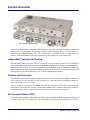
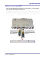
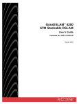
TITLE PAGE
Wide Bank 28 DS3
TL1 JOB AID
Fan Faceplate Option (FFO)
Document: 002-0138-0100
Product Release: 2.4
March 2003
Copyright© 2003 Carrier Access Corporation. All rights reserved.
The information presented in this manual is subject to change without notice and does not represent a
commitment on the part of Carrier Access Corporation. The hardware and software described herein are
furnished under a license or non-disclosure agreement. The hardware, software, and manual may be used or
copied only in accordance with the terms of this agreement. It is against the law to reproduce, transmit,
transcribe, store in a retrieval system, or translate into any medium - electronic, mechanical, magnetic, optical,
chemical, manual, or otherwise - any part of this manual or software supplied with the Wide Bank for any
purpose other than the purchaser’s personal use without the express written permission of Carrier Access
Corporation.
Wide Bank and the Carrier Access Logo are registered trademarks of Carrier Access Corporation. All other
brand or product names are trademarks or registration trademarks of their respective companies or
organizations.
Contact Information:
Carrier Access Corporation
5395 Pearl Parkway
Boulder, CO 80301-2490
Corporate Phone: (800) 495-5455
Fax: (303) 443-5908
www.carrieraccess.com
Customer Support Direct: (800) 786-9929
E-mail: [email protected]
TABLE OF CONTENTS
Communicating with the System
n
System Overview. . . . . . . . . . . . . . . . . . . . . . . . . . . . . . . . . . . 2
n
Guidelines . . . . . . . . . . . . . . . . . . . . . . . . . . . . . . . . . . . . . . . . . . 4
n
Access Identifiers
n
Log-In/Log-Out Commands . . . . . . . . . . . . . . . . . . . . . . . 10
n
Present State Definitions (PST) . . . . . . . . . . . . . . . . . . . . 13
.................................. 6
Configuration
n
System ID . . . . . . . . . . . . . . . . . . . . . . . . . . . . . . . . . . . . . . . . . 16
n
System Time of Day. . . . . . . . . . . . . . . . . . . . . . . . . . . . . . . 17
n
T3 Circuit Configuration . . . . . . . . . . . . . . . . . . . . . . . . . . 18
n
T3 Protection and Revertive Configuration . . . . . . . . 20
n
T1 Circuit Configuration . . . . . . . . . . . . . . . . . . . . . . . . . . 22
n
E1 Circuit Configuration . . . . . . . . . . . . . . . . . . . . . . . . . . 24
n
T1/E1 Protection and Revertive Configuration
n
T1/E1 Auto In-Service Detection (LOS Inhibit) . . . 30
. . . . 26
Circuit Testing
n
Diagnostics . . . . . . . . . . . . . . . . . . . . . . . . . . . . . . . . . . . . . . . . 32
n
Loopbacks. . . . . . . . . . . . . . . . . . . . . . . . . . . . . . . . . . . . . . . . . 34
Performance Monitoring
n
PM Reports
. . . . . . . . . . . . . . . . . . . . . . . . . . . . . . . . . . . . . . . 38
Trouble Retrieval
n
Retrieve Condition . . . . . . . . . . . . . . . . . . . . . . . . . . . . . . . . 40
n
Retrieve Alarms . . . . . . . . . . . . . . . . . . . . . . . . . . . . . . . . . . . 41
n
Retrieve Logs
n
Alarm and Event Message Parameters . . . . . . . . . . . . . 43
. . . . . . . . . . . . . . . . . . . . . . . . . . . . . . . . . . . . . 42
System Overview
System Overview
Fan Faceplate Option (FFO)
Carrier Access Corporation’s Wide Bank 28 DS3 Multiplexer provides a standards-based M13 multiplexing
function with TL1 management. This product converts a framed Digital Signal Level 3 (DS3) network
connection into 28 Digital Signal Level 1 (DS1) connections to T1 facilities, or into 21 connections to E1
facilities. Each Wide Bank 28 DS3 can be equipped with DS1 cards or E1 cards, but not both.
Independent Framing and Clocking
The Wide Bank 28 DS3 does not re-frame or re-clock the low-speed inputs. It allows T1 or E1 framing to
be provided independently by the connected communications equipment at both the near-end and the farend of the DS3 line. Each T1 or E1 is also independently clocked within the M13 formatted DS3 composite.
Because of the independent clocking and framing capabilities for each of the T1 or E1 connections, the Wide
Bank 28 DS3 can provide asynchronous T1 or E1 to DS3 multiplexing functions.
Capacity and Protection
The Wide Bank 28 DS3 unit’s modular design provides up to seven active quad DS1 (QDSX) cards or seven
active triple-port E1 cards. One spare circuit card (DS1 or E1) provides software-controlled protection of
low-speed interfaces on a 1 to 7 basis.
The DS3 Controller card provides all common electronic functions of power conversion, processing and
management, and a single DS3 interface. An optional redundant DS3 Controller card provides protection
for both electronic common equipment and a second DS3 interface for network protection.
Fan Faceplate Option (FFO)
The Fan Faceplate Option provides additional cooling capacity so that Wide Bank units can be installed with
no space between units. This enables up to 40 Wide Banks (1120 DS1s) to be installed in one 7-foot rack.
2
Wide Bank 28 DS3 - Release 2.4
System Overview
Maintenance Service Option (MSO)
In addition to providing the same circuit failure protection as Standard DS1 and E1 cards, the MSO DS1
and E1 cards can be replaced without interrupting service on other circuits. The TL1 Access Identifiers
clearly distinguish between standard cards and MSO cards.
The MSO circuit card is made up of two separating sections called the MSO Electronics card and the MSO
Relay card. By separating these sections, a customer can replace the failed DS1 or E1 electronic circuits on
the MSO Electronics card while the MSO Relay card automatically maintains the four DS1 (or three E1)
circuits by switching them to the spare card. Once new MSO Electronics are inserted and pass self-test, the
circuits on the spare card are automatically switched back to the home circuits.
With MSO Relay card
installed in chassis, the
MSO Electronics card
can be removed without
interrupting service
Wide Bank 28 DS3 - Release 2.4
MSO circuit card assembly,
comprising MSO Electronics
card and MSO Relay card,
replaces standard low-speed
circuit card
3
Guidelines
Guidelines
TL1 Command Syntax
TL1 commands are not case sensitive and may be entered using “UPPER CASE” or “lower case” characters.
For simplicity, this Job Aid uses the following conventions:
l “UPPER CASE” characters denote Command words and Modifiers
l “lower case” characters denote Keywords in commands and are accompanied by a table listing
permissible values. Default values in the table are shown in bold type.
l { } braces denote required keywords that must be present.
l [ ] brackets denote optional keywords that may be omitted. An accompanying table will list the
default value in bold type.
l Target Identifier (tid) may be optional or required. The network architecture may require a tid in
order to access the element. To save space in this document, the tid is not enclosed in brackets. If
a tid is included in a command, it must be correct or the command will be denied.
l Correlation Tag (ctag) is usually optional. To save space in this document, the ctag is not enclosed
in brackets. The ctag is an alphanumeric string that is echoed back in the response message for
each command.
l Access Identifier (aid) is usually required. The aid will be enclosed in brackets only if it is
optional. Refer to the accompanying tables in each command for permissible values and the
default value if omitted.
l List and Range notations using single and double ampersands (& and &&) are supported for T1
and E1 aids in most commands.
List example for DS1s 1, 3, 5:
Range example for DS1s 5 thru 8:
RTRV-T1:tid:DS1-1&DS1-3&DS1-5:ctag;
RTRV-T1:tid:DS1-5&&DS1-8:ctag;
TL1 Shortcuts (Recall and Edit)
To simplify entering repetitive commands, the Wide Bank allows you to “recall” the previous ten
commands entered by pressing the up and down arrow keys. You can also edit TL1 commands by using the
backspace key to delete mistakes and retyping characters.
Provisioning New Circuits
Configure the system parameters
l Retrieve and verify the System Identifier (see System ID on page 16)
l Retrieve and verify the System Clock (see System Time of Day on page 17)
Configure the first facility
l Retrieve one of the facilities to verify parameters and present state
l The present state of the T3 facility is always in service and equipped (IS-EQ)
l Check the present state of T1 and E1 facilities to verify that the facility is available
l If necessary, enter or edit the facility parameters and place the facility in service
4
Wide Bank 28 DS3 - Release 2.4
Guidelines
l Retrieve the facility to verify parameters and present state
l Retrieve the facility condition to verify normal operation (see Retrieve Condition on page 40)
l Retrieve the facility alarms to verify normal operation (see Retrieve Alarms on page 41)
Configure the next facility
l Repeat the above items to configure each of the remaining facilities
Test the facilities
l Follow standard practices to test each facility
l If desired, use the Diagnostics on page 32 and Loopbacks on page 34
Provisioning Existing Circuits
Configure the first facility
l Retrieve one of the facilities to verify parameters and present state
l The present state of the T3 facility is always in service and equipped (IS-EQ)
l Check the present state of T1 and E1 facilities to verify that the facility is available
l If necessary, enter or edit the facility parameters and place the facility in service
l Retrieve the facility to verify parameters and present state
l Retrieve the facility condition to verify normal operation (see Retrieve Condition on page 40)
l Retrieve the facility alarms to verify normal operation (see Retrieve Alarms on page 41)
Configure the next facility
l Repeat the above items to configure each of the remaining facilities
Test the facilities
l Follow standard practices to test each facility
l If desired, use the Diagnostics on page 32 and Loopbacks on page 34.
Available Test Functions
l Verify IP network connectivity to the Wide Bank with a PING command
l After login, verify normal Wide Bank response with the RTRV-HDR command
l Diagnose fans, E1, and T1 circuits with the DGN-{ENV|E1|T1} command
l Allow detection of loopback codes with the ALW-LPBK-{E1|T1|T3} command
l Send loopback codes with the CONN-LPBK-{E1|T1|T3} command
l Operate loopbacks with the OPR-LPBK-{E1|T1|T3} command
Wide Bank 28 DS3 - Release 2.4
5
Access Identifiers
Access Identifiers
T3-T1 Configuration AIDs
T1 AIDs
DS1-01
DS1-02
DS1-03
DS1-04
DS1-05
DS1-06
DS1-07
DS1-08
DS1-09
DS1-10
DS1-11
DS1-12
DS1-13
DS1-14
DS1-15
DS1-16
DS1-17
DS1-18
DS1-19
DS1-20
DS1-21
DS1-22
DS1-23
DS1-24
DS1-25
DS1-26
DS1-27
DS1-28
6
Wide Bank 28 DS3
Quad DS1
Card Slot 1
A
B
C
D
Quad DS1
Card Slot 2
A
B
C
D
Quad DS1
Card Slot 3
A
B
C
D
Quad DS1
Card Slot 4
A
B
C
D
Quad DS1
Card Slot 5
A
B
C
D
Quad DS1
Card Slot 6
A
B
C
D
Quad DS1
Card Slot 7
A
B
C
D
Quad DS1
Spare Slot
A
B
C
D
T3 AIDs
DS3 Controller
Card Slot A
(Primary)
DS3-A
DS3 Controller
Card Slot B
(Secondary)
DS3-B
Used only for DS3
Network Protection
Four DS1
Protection
Groups
Wide Bank 28 DS3 - Release 2.4
Access Identifiers
T3-T1 Equipment AIDs
MSO only with
Maintenance
Service Option
DS1-CARD-1
DS1-CARD-MS0-1
Wide Bank 28 DS3
Quad DS1
Card Slot 1
Fans only with
Fan Faceplate
Option (FFO)
FAN-A
DS1-CARD-2
DS1-CARD-MS0-2
Quad DS1
Card Slot 2
POWER-5V-A
DS1-CARD-3
DS1-CARD-MS0-3
DS1-CARD-4
DS1-CARD-MS0-4
EXT48V-A
Quad DS1
Card Slot 3
Quad DS1
Card Slot 4
DS3 Controller
Card Slot A
(Primary)
POWER-5V-B
DS1-CARD-5
DS1-CARD-MS0-5
EXT48V-B
Quad DS1
Card Slot 5
DS1-CARD-6
DS1-CARD-MS0-6
Quad DS1
Card Slot 6
DS1-CARD-7
DS1-CARD-MS0-7
Quad DS1
Card Slot 7
DS1-CARD-SPARE
E1-CARD-MSO-SPARE
Quad DS1
Spare Slot
Wide Bank 28 DS3 - Release 2.4
DS3-A
DS3 Controller
Card Slot B
(Secondary)
DS3-B
FAN-B
7
Access Identifiers
T3-E1 Configuration AIDs
E1 AIDs
E1-01
E1-02
E1-03
8
Wide Bank 28 DS3
Triple E1
Card Slot 1
T3 AIDs
A
B
C
E1-05
E1-06
E1-07
Triple E1
Card Slot 2
A
B
C
E1-09
E1-10
E1-11
Triple E1
Card Slot 3
A
B
C
E1-13
E1-14
E1-15
Triple E1
Card Slot 4
A
B
C
E1-17
E1-18
E1-19
Triple E1
Card Slot 5
A
B
C
E1-21
E1-22
E1-23
Triple E1
Card Slot 6
A
B
C
E1-25
E1-26
E1-27
Triple E1
Card Slot 7
A
B
C
Triple E1
Spare Slot
A
B
C
DS3 Controller
Card Slot A
(Primary)
DS3-A
DS3 Controller
Card Slot B
(Secondary)
DS3-B
Used only for DS3
Network Protection
Three E1
Protection
Groups
Wide Bank 28 DS3 - Release 2.4
Access Identifiers
T3-E1 Equipment AIDs
MSO only with
Maintenance
Service Option
E1-CARD-1
E1-CARD-MS0-1
Wide Bank 28 DS3
Triple E1
Card Slot 1
Fans only with
Fan Faceplate
Option (FFO)
FAN-A
E1-CARD-2
E1-CARD-MS0-2
Triple E1
Card Slot 2
POWER-5V-A
E1-CARD-3
E1-CARD-MS0-3
E1-CARD-4
E1-CARD-MS0-4
EXT48V-A
Triple E1
Card Slot 3
Triple E1
Card Slot 4
DS3 Controller
Card Slot A
(Primary)
POWER-5V-B
E1-CARD-5
E1-CARD-MS0-5
E1-CARD-6
E1-CARD-MS0-6
E1-CARD-7
E1-CARD-MS0-7
E1-CARD-SPARE
E1-CARD-MSO-SPARE
Wide Bank 28 DS3 - Release 2.4
DS3-A
EXT48V-B
Triple E1
Card Slot 5
Triple E1
Card Slot 6
Triple E1
Card Slot 7
DS3 Controller
Card Slot B
(Secondary)
DS3-B
FAN-B
Triple E1
Spare Slot
9
Log-In/Log-Out Commands
Log-In/Log-Out Commands
1. Activate User (Log In)
NOTE:
To simplify new installations, units are normally shipped with log-in security turned
off unless the customer requests that it be turned on. When security is turned on, the default
user name is ADMIN and the default password is either null or TEST.
ACT-USER:tid:uid:ctag::pid;
Keyword
Description
pid
Private ID (password). An ASCII string up to 10 characters long with at least
two non-alphabetic characters with at least one special character. Omit if no
password is required. Passwords are case-sensitive
uid
User ID (name). An alphanumeric string up to 10 characters long.
Example: ACT-USER:tid:JOHNDOE:ctag::SECRET-1;
NOTE: If user’s name and password are valid, a normal COMPLD response will appear.
Following each login, the Wide Bank automatically retrieves the current equipment
configuration (RTRV-EQPT) to display the installed cards and their present status, as shown
below.
Response:
M
;
A
tid 2001-12-18 15:13:21
ctag COMPLD
tid 2001-12-18 15:13:21
1 REPT EQPT
"DS3-A:ACTIVE,2.40.0"
"DS3-B:STANDBY,2.40.0"
"DS1-CARD-1:ACTIVE,"
"DS1-CARD-2:ACTIVE,"
"DS1-CARD-3:ACTIVE,"
"DS1-CARD-4:ACTIVE,"
"DS1-CARD-5:ACTIVE,"
"DS1-CARD-6:ACTIVE,"
"DS1-CARD-7:ACTIVE,"
"DS1-CARD-SPARE:ACTIVE,"
;
10
Wide Bank 28 DS3 - Release 2.4
Log-In/Log-Out Commands
2. Edit PID (Change Password)
ED-PID:tid:uid:ctag::old-pid,new-pid;
Keyword
Description
uid
User ID
new-pid
New Private ID (password). An ASCII string up to 10 characters long with at
least two non-alphabetic characters with at least one special character. Null
removes password requirement. Passwords are case-sensitive.
old-pid
Old Private ID (password)
Example: ED-PID:tid:name:ctag::old-1,new-1;
3. Cancel User (Log Out)
CANC-USER:tid:uid:ctag;
Keyword
Description
uid
User ID (optional for log out)
Example: CANC-USER:tid:name:ctag;
Response:
M
;
tid 2001-12-18 16:07:31
ctag COMPLD
4. Cancel User Session Message
The TL1 session time-out period is set by the system administrator. The default value is 31 minutes. This
time-out will cancel the user session when the specified period of inactivity is exceeded. If two or more users
have active sessions and one user session times out, the other users will receive a CANC message. In the
following example, STEVE is the user that timed out:
Response:
tid 2001-12-04 11:40:32
A atag CANC
STEVE
/* Session Timeout: STEVE */
;
Wide Bank 28 DS3 - Release 2.4
11
Log-In/Log-Out Commands
5. Set User Session Timeout
This command is used by the system administrator to set the number of minutes before session inactivity
timeout of the TL1 TCP/IP port. When the command is issued, any active sessions will be updated with the
new session timeout period. Setting the tmout parameter to zero will turn off session inactivity timeouts so
that sessions will never time out.
This command does not affect TL1 sessions using the TL1 RS-232 port or any CLI sessions using TCP/IP
or RS-232.
SET-ATTR-SECUDFLT:tid::ctag::TMOUT=<tmout>;
Keyword
Description
tmout
Timeout period in minutes.
• Any positive integer value.
• A zero value will disable timeout.
• Default value is 31.
Example: SET-ATTR-SECUDFLT:tid::ctag::TMOUT=15;
12
Wide Bank 28 DS3 - Release 2.4
Present State Definitions (PST)
Present State Definitions (PST)
1. Retrieve T3 Present State
NOTE:
The T3 facility’s Present State value is always in service and equipped (IS-EQ).
RTRV-T3:tid:[aid]:ctag;
Keyword
Description
aid
Access ID (optional). If omitted, it will default to ALL.
• ALL
ctag
Correlation Tag (optional)
tid
Target ID of network element (optional)
Example: Retrieve current DS3 configuration.
RTRV-T3:tid::ctag;
The following response shows the default DS3 configuration values (see T3 Circuit
Configuration on page 18).
Response:
tid 2001-12-4 11:43:56
ctag COMPLD
"AISC=LOS&AISNAS&LOF,AIST=ONES,CKTID=DS3,
CMDMDE=FRCD,FMT=M23,IDLE=N,LBO=1,LINECDE=B3ZS,
MCOND=LOS&RAI&AISNAS&LOF&T-ERL&RTCLK&IMPROPRMVL&
IRR&CONTEQPT&BPV,OMODE=NORM,XBIT=PASS,XBITRCV=ALM1,
XPOL=ALM1,TMG=INT,TMGLOCK=N"
;
M
Wide Bank 28 DS3 - Release 2.4
13
Present State Definitions (PST)
2. Retrieve T1 or E1 Present State
RTRV-T1:tid:aid:ctag;
RTRV-E1:tid:aid:ctag;
Keyword
Description
aid
Access ID depends on facility type:
• For T1 facility, use DS1-1 to DS1-28, or ALL
• For E1 facility, use E1-01 to E1-27, or ALL
(see T3-E1 Configuration AIDs on page 8)
Note: This command supports aid lists and ranges (&, &&).
ctag
Correlation Tag (optional)
tid
Target ID of network element (optional)
Example: Retrieve the current configuration, including the PST and SST values, for E1 #2.
RTRV-E1:tid:E1-02:ctag;
Example: Retrieve the current configuration, including the PST and SST values, for DS1 #2.
RTRV-T1:tid:DS1-02:ctag;
The following response shows the default DS1 configuration values (see T1 Circuit
Configuration on page 22).
tid 2001-12-04 11:51:58
ctag COMPLD
"DS1-02::AISF=Y,CMDMDE=FRCD,DLCID=DS1 2,
FLMDE=BOTH,FMT=UNFR,IDLE=AIS,LBO=1,LINECDE=B8ZS,
OMODE=NORM,RVRTFLAG=UNLCKD:IS-EQ,NALMNR"
;
M
PST
14
SST
Wide Bank 28 DS3 - Release 2.4
Present State Definitions (PST)
PST and SST Values
PST Keyword
Description
T1 and E1 facilities may have the following Primary State (PST) values.
IS-EQ
In service (enabled) and equipped
IS-RLY
In service with relay card only (transceiver electronics card is removed)
IS-UEQ
In service and unequipped
OOS-EQ
Out of service (disabled) and equipped
OOS-RLY
Out of service with relay card only (transceiver electronics card is removed)
OOS-UEQ
Out of service and unequipped
SST Keyword
Description
T1 and E1 facilities may have the following Secondary State (SST) values.
NALMNR
The automatic in-service feature \is turned on and an LOS alarm is being
suppressed on this DS1
NALMCD
The automatic in-service feature is turned on, a good DS1 signal exists, but it
has not persisted for 2 minutes yet
Wide Bank 28 DS3 - Release 2.4
15
System ID
System ID
The following steps show how to set the System ID (sid) that appears as in all TL1 messages and is
required as the Target ID (tid) when used in TL1 commands.
1. Retrieve Current Equipment Configuration
NOTE:
The following command is executed automatically when the user logs in.
RTRV-EQPT:tid:[ALL]:ctag;
Example: RTRV-EQPT:tid:ALL:ctag;
Response:
M
tid 2002-01-05 11:21:39
ctag COMPLD
"DS3-A:ACTIVE,2.40.0"
"DS3-B:STANDBY,2.40.0"
"DS1-CARD-1:ACTIVE,"
"DS1-CARD-2:ACTIVE,"
"DS1-CARD-3:ACTIVE,"
"DS1-CARD-4:ACTIVE,"
"DS1-CARD-5:ACTIVE,"
"DS1-CARD-6:ACTIVE,"
"DS1-CARD-7:ACTIVE,"
"DS1-CARD-SPARE:ACTIVE,"
;
2. Set System ID
SET-SID:tid::ctag::sid;
Example: Change System Equipment ID from tid to MUX-1.
SET-SID:tid::ctag::MUX-1;
Response:
M
;
tid 2002-01-05 11:23:48
ctag COMPLD
The first response following the SET-SID command will display the original tid so that
the response can be matched to the command. Subsequent commands and responses
will use the new tid.
16
Keyword
Description
sid
System ID: Up to 20 alphanumeric or hyphen characters
Wide Bank 28 DS3 - Release 2.4
System Time of Day
System Time of Day
The following steps show how to reset the Wide Bank system clock.
NOTE: The Wide Bank system clock must be reset after a power interruption. The clock
date and time are used to time-stamp all alarms, events, and logs. Following a power
interruption, the date and time will restart at 2001-01-01 01:00:00.
1. Retrieve Time of Day
RTRV-TOD:tid::ctag;
Example: RTRV-TOD:tid::ctag;
Response:
tid 2001-01-01 11:51:46
M ctag COMPLD
"2001,01,01,11,51,46"
;
2. Edit Time of Day
ED-DAT:tid::ctag::yy-mm-dd,hh-mm-ss;
Example: Set date to 2001 December 5 and time to 11:20:00 a.m.
ED-DAT:tid::ctag::01-12-05,11-20-00;
Response:
M
;
tid 2001-12-05 11:20:00
ctag COMPLD
Keyword
Description
yy-mm-dd
Date:
• yy – Last 2 digits of year
• mm – Month: 01 to 12
• dd – Day: 01 to 31
hh-mm-ss
Time:
• hh – Hours: 00 to 23
• mm – Minutes: 00 to 59
• ss – Seconds: 0 to 59
Wide Bank 28 DS3 - Release 2.4
17
T3 Circuit Configuration
T3 Circuit Configuration
The following steps show how to configure the T3 (DS3) facility.
NOTE:
The Wide Bank T3 facility is always In Service and Equipped (IS-EQ).
1. Retrieve Current T3 Configuration
RTRV-T3:tid:[aid]:ctag;
Keyword
Description
aid
Access ID (optional). If omitted, it will default to ALL.
• ALL
Example: Retrieve the current DS3 configuration.
RTRV-T3:tid:ALL:ctag;
The following response shows the default configuration.
NOTE:
The response may include current alarms and inhibits.
Response:
tid 2001-12-4 11:43:56
M ctag COMPLD
"AISC=LOS&AISNAS&LOF,AIST=ONES,CKTID=DS3,
CMDMDE=FRCD,FMT=M23,IDLE=N,LBO=1,LINECDE=B3ZS,
MCOND=LOS&RAI&AISNAS&LOF&T-ERL&RTCLK&IMPROPRMVL&
IRR&CONTEQPT&BPV,OMODE=NORM,XBIT=PASS,XBITRCV=ALM1,
XPOL=ALM1,TMG=INT,TMGLOCK=N"
;
2. Edit T3 Configuration
ED-T3:tid:aid:ctag:::[CKTID=cktid],[FMT=fmt],[LBO=lbo],[OMODE=omode],
[TMG=tmg],[TMGLOCK=tmglock];
Keyword
Description
aid
Access ID
• ALL
Example: Set DS3 frame format to C-bit.
ED-T3:tid:ALL:ctag:::FMT=CBIT;
18
Wide Bank 28 DS3 - Release 2.4
T3 Circuit Configuration
T3 Configuration Parameters
Keyword
Description
aid
Access ID. Required for ED-T3 command.
• ALL
AISC=
Specifies conditions on the input (receive) side of a connection under which AIS will be
generated on the output (transmit) side of a connection. Hard-coded to
LOS&AISNAS&LOF.
AIST=
Indicates the type of the AIS signal to be generated/transmitted, and the AIS signal
mode expected on input should a failure condition exist. Hard-coded to ONES.
CKTID=
The circuit identification parameter contains the Common Language Circuit ID or other
alias of the channel being provisioned. This is an ASCII string limited to 32 characters.
CMDMDE=
Indicates command execution mode. Hard-coded to FRCD, meaning that commands
may override existing parameter settings in order to execute.
FMT=
Indicates DS3 digital signal format. Values are:
• CBIT
• M23
IDLE=
Indicates DS3 idle signal is used or not used. Hard-coded to N.
LBO=
Indicates line build out setting. Values are:
• 1 – short connections (less than 50')
• 2 – long connections (50' or longer)
LINECDE=
Indicates DS3 line code. Hard coded to B3ZS.
MCOND=
Specifies conditions to be monitored on the input side of the connection. Hard-coded to:
LOS&RAI&AISNAS&LOF&T-BERL&RTCLK&IMPROPRMVL&INT
&PWR&INTERR&CONTEQPT&BPV
OMODE=
Specifies what will be transmitted from the DS3 output port. Values are:
• NORM – normal
• AIS – Alarm Indication Signal
TMG=
Timing Source. Applies only to T3 modifier. Values are:
• INT – Internal Stratum 4E clock
• EXT – External Clock (44.736 Mbps)
• LINE – Slave to DS3 Line
TMGLOCK=
Timing Lock. Applies only to T3 modifier. Indicates whether provisioned timing source
is to be locked to disable automatic source switching. Values are:
• Y – yes
• N – no
XBIT=
Indicates how the X-bits are handled for this particular channel. Hard-coded to PASS,
meaning it will pass the X-bits with no modification.
XBITRCV=
Indicates the usage of the outgoing X-bits. Hard-coded to ALM1, meaning all the Xbits equal to 1 for indicating incoming remove alarm.
XPOL=
Indicates the value/polarity to which the outgoing X-bits are forced. Hard-coded to
ALM1, meaning the Wide Bank will set X-bits to one for indicating alarm.
Wide Bank 28 DS3 - Release 2.4
19
T3 Protection and Revertive Configuration
T3 Protection and Revertive Configuration
The following steps show how to retrieve the current DS3 equipment configuration and condition, and how to
change the DS3 protection and revertive properties. The unit can also provide automatic protection switching
(APS) if it has two DS3 lines as well as two DS3 controller cards.
1. Retrieve Current T3 Equipment Configuration
This will show the status of the DS3 controller cards and whether the unit can provide high-speed protection.
RTRV-EQPT:tid:[ALL]:ctag;
Example: RTRV-EQPT:tid:ALL:ctag;
Response:
M
tid 2001-08-04 05:08:45
ctag COMPLD
"DS3-A:ACTIVE,2.40.0"
"DS3-B:STANDBY,2.40.0"
"DS1-CARD-1:ACTIVE,"
"DS1-CARD-2:ACTIVE,"
"DS1-CARD-3:ACTIVE,"
"DS1-CARD-4:ACTIVE,"
"DS1-CARD-5:ACTIVE,"
"DS1-CARD-6:ACTIVE,"
"DS1-CARD-7:ACTIVE,"
"DS1-CARD-SPARE:ACTIVE,"
Status of DS3 controller cards.
Unit can provide high-speed
protection if one DS3 is ACTIVE
and one is STANDBY.
;
T3 Equipment Status Values
20
Equipment
Status
Description
DS3 -A, DS3-B
Active
Controller card is installed and in active mode (DS3 circuit
is active)
Standby
Controller is installed and in standby mode
Not Present
Controller is not installed
Not Ready
Controller is present, but is not communicating with the
active card for unknown reasons
Fail
Controller hardware failure
Wide Bank 28 DS3 - Release 2.4
T3 Protection and Revertive Configuration
2. Retrieve Current T3 Condition
RTRV-COND-T3:tid::ctag;
Example: RTRV-COND-T3:tid::ctag;
Response:
M
If T3:PROTNA appears, protection is not
available, either because the second
controller is not installed or has failed.
tid 2001-08-04 05:05:51
ctag COMPLD
"DS3-A,T3:PROTNA,NSA,,,,,,\"Protection Unit not Available\""
"DS3-A,T3:IHNSWPR,NSA,,,,,,\"DS3 Facility Protection not Enabled\""
"DS3-A,T3:INHAUTORSTEQPT,NSA,,,,,,\"DS3 Revertive Off\""
;
3. Determine T3 Protection and Revertive Choices
If DS3 condition is
Your choice is
T3:IHNSWPR
Allow DS3 automatic protection switching:
ALW-SWTOWKG-T3:tid:ALL:ctag;
T3:IHNSWPR
(does not appear)
Inhibit DS3 automatic protection switching:
INH-SWTOWKG-T3:tid:ALL:ctag;
T3:INHAUTORSTEQPT
Allow DS3 revertive switching to DS3-A:
ALW-AUTORST:tid::ctag::DS3EQPT;
T3:INHAUTORSTEQPT
(does not appear)
Inhibit DS3 revertive switching:
INH-AUTORST:tid::ctag::DS3EQPT;
4. To Switch T3 to Protection or Working Controller
The following commands will forcibly move the T3 circuit between the working (DS3-A) and protection
(DS3-B) controllers for testing or maintenance. Switching will be denied only if the equipment status
(RTRV-EQPT) of the other controller is NOT PRESENT (not equipped) or UNKNOWN (equipped but
status unknown).
CAUTION! THESE COMMANDS MAY AFFECT SERVICE. BEFORE SWITCHING
CONTROLLERS, IT IS ADVISABLE TO PERFORM A RTRV-ALM-T3 TO VERIFY THAT THERE
ARE NO EXISTING DS3 ALARMS ON THE OTHER CONTROLLER.
NOTE:
If you switch DS3 controllers, your current TL1 session will be terminated. When
you start another TL1 session, you will be logging into the newly active controller.
SW-TOPROTN-T3:tid:ALL:ctag;
SW-TOWKG-T3:tid:ALL:ctag;
Wide Bank 28 DS3 - Release 2.4
21
T1 Circuit Configuration
T1 Circuit Configuration
1. Retrieve Current T1 Configuration
RTRV-T1:tid:aid:ctag;
AIDType AID
T1
DS1-1 to DS1-28, or ALL
Note: Most T1 commands
support lists and ranges
Example: Retrieve current configuration for
DS1 #2.
RTRV-T1:tid:DS1-02:ctag;
Response:
tid 2001-12-04 11:51:58
M ctag COMPLD
"DS1-02::AISF=Y,CMDMDE=FRCD,DLCID=DS1 2,
FLMDE=BOTH,FMT=UNFR,IDLE=AIS,LBO=1,LINECDE=B8ZS,
OMODE=NORM,RVRTFLAG=UNLCKD:IS-EQ,NALMNR"
;
PST
2. Determine T1 Configuration Choices
If PST=
Your choice is
IS-EQ
IS-RLY
IS-UEQ
Edit a parameter while in service:
ED-T1:tid:aid:ctag:::t1_parameters];
OOS-EQ
OOS-RLY
OOS-UEQ
Edit a parameter while out of service:
ED-T1:tid:aid:ctag:::t1_parameters];
Place a facility out of service:
RMV-T1:tid:aid:ctag;
Enter (grow) a facility and place in service:
ENT-T1:tid:aid:ctag:::t1_parameters];
3. To Edit T1 Configuration
ED-T1:tid:aid:ctag:::[DLCID=dlcid],[LBO=lbo],[LINECDE=linecde],[OMODE=omode];
Example: Set DS1 #8 Line Code to AMI.
ED-T1:tid:DS1-08:ctag:::LINECDE=AMI;
4. To Enter T1 Configuration and Put In Service
ENT-T1:tid:aid:ctag:::[DLCID=dlcid],[LBO=lbo],[LINECDE=linecde],[OMODE=omode];
Example: Create DS1 #8 with Line Code set to AMI and place in service.
ENT-T1:tid:DS1-08:ctag:::LINECDE=AMI;
22
Wide Bank 28 DS3 - Release 2.4
T1 Circuit Configuration
5. To Remove T1 From Service
CAUTION! REMOVING A T1 WILL DISRUPT SERVICE.
RMV-T1:tid:aid:ctag;
Example: Place DS1 #8 out of service.
RMV-T1:tid:DS1-08:ctag;
T1 Configuration Parameters
Keyword
Description
AISF=
Indicates whether failed signal from upstream should be replaced by AIS. Hardcoded to Y.
CMDMDE=
Indicates command execution mode. Hard-coded to FRCD. This means that
existing parameter settings may be overridden in order to execute the command.
DLCID=
The DS1 digital loop carrier system identifier. This is a string of ASCII
characters and has a maximum length of 32 characters.
FLMDE=
Indicates the fault locate mode. Hard-coded to BOTH.
FMT=
Indicates DS1 digital signal format. Hard-coded to UNFR.
IDLE=
Indicates the signal inserted for idle DS1. Hard-coded to AIS.
LBO=
Indicates the line buildout setting. Values are 1-6.
• 1 – DSX(0’-110’)
• 2 – DSX(110’-220’)
• 3 – DSX(220’-330’)
• 4 – DSX(330’-440’)
• 5 – DSX(440’-550’)
• 6 – DSX(550’-660’)
LINECDE=
Indicates DS1 line code. Values are:
• AMI – Alternate mark inversion
• B8ZS – Bipolar with 8-zero substitution
OMODE=
Specifies what will be transmitted from the DS1 output port. Values are:
• NORM – Normal
• AIS – Alarm Indication Signal
RVRTFLAG=
• UNLCKD – Unlocked. DS1 will revert to home.
• LOCKED – Indicates if the DS1 is locked onto the spare due to repeated
unsuccessful attempts at reverting to the working card (three attempts in 24
hours). The DS1 will remain on the spare until this flag is cleared, the DS1
card is replaced, or the DS1 is manually moved home (SW-TOWKG-T1).
Wide Bank 28 DS3 - Release 2.4
23
E1 Circuit Configuration
E1 Circuit Configuration
1. Retrieve Current E1 Configuration
RTRV-E1:tid:aid:ctag;
Example: Retrieve configuration for E1 #1.
AIDType AID
E1
E1-01 to E1-27, or ALL
(see T3-E1 Configuration
AIDs on page 8)
RTRV-E1:tid:E1-01:ctag;
Response:
tid 2001-08-04
11:47:18
M ctag COMPLD
"E1-01::AISF=Y,CMDMDE=FRCD,DLCID=E1 1,
FLMDE=BOTH,FMT=UNFR,IDLE=AIS,LINECDE=HDB3,
OMODE=NORM,RVRTFLAG=UNLCKD:IS-EQ,NALMNR"
;
PST
2. Determine E1 Configuration Choices
If PST=
Your choice is
IS-EQ
IS-RLY
IS-UEQ
Edit a parameter while in service.
ED-E1:tid:aid:ctag:::[DLCID=dlcid],[OMODE=omode];
OOS-EQ
OOS-RLY
OOS-UEQ
Edit a parameter while out of service
ED-E1:tid:aid:ctag:::[DLCID=dlcid],[OMODE=omode];
Place a facility out of service.
RMV-E1:tid:aid:ctag;
Enter (grow) a facility and place in service (ENT-E1)
RMV-E1:tid:aid:ctag;
3. To Edit E1 Configuration
ED-E1:tid:aid:ctag:::[DLCID=dlcid],[OMODE=omode];
Example: Set E1 #3 Circuit ID to WB6-E1-03.
ED-E1:tid:E1-03:ctag:::DLCID=WB6-E1-03;
4. To Enter E1 Configuration and Put In Service
ENT-E1:tid:aid:ctag:::[DLCID=dlcid],[OMODE=omode];
Example: Create E1 #3 with Circuit ID set to WB6-E1-03 and place in service.
ENT-E1:tid:E1-03:ctag:::DLCID=WB6-E1-03;
24
Wide Bank 28 DS3 - Release 2.4
E1 Circuit Configuration
5. To Remove E1 From Service
CAUTION! REMOVING AN E1 WILL DISRUPT SERVICE.
RMV-E1:tid:aid:ctag;
Example: Place DS1 #3 out of service.
RMV-E1:tid:E1-03:ctag;
E1 Configuration Parameters
E1 facilities are hardcoded to HDB3 line code and no line buildout.
Keyword
Description
AISF=
Indicates whether failed signal from upstream should be replaced by AIS. Hardcoded to Y.
CMDMDE=
Indicates command execution mode. Hard-coded to FRCD. This means that
existing parameter settings may be overridden in order to execute the command.
DLCID=
The E1 digital loop carrier system identifier. This is a string of ASCII
characters and has a maximum length of 32 characters.
FLMDE=
Indicates the fault locate mode. Hard-coded to BOTH.
FMT=
Indicates E1 digital signal format. Hard-coded to UNFR.
IDLE=
Indicates the signal inserted for idle E1. Hard-coded to AIS.
LINECDE=
Indicates E1 line code. E1 is always HDB3 (high density bipolar 3).
OMODE=
Specifies what will be transmitted from the E1 output port. The Wide Bank
supports:
• NORM – Normal
• AIS – Alarm Indication Signal
RVRTFLAG=
• UNLCKD – Unlocked. E1 will revert to home.
• LOCKED – Indicates if the E1 is locked onto the spare due to repeated
unsuccessful attempts at reverting to the working card (three attempts in 24
hours). The E1 will remain on the spare until this flag is cleared, the E1 card
is replaced, or the E1 is manually moved home (SW-TOWKG-E1).
Wide Bank 28 DS3 - Release 2.4
25
T1/E1 Protection and Revertive Configuration
T1/E1 Protection and Revertive Configuration
The following steps show how to retrieve the current T1/E1 equipment configuration and condition,
and how to change the T1/E1 protection and revertive properties.
1. Retrieve Current T1/E1 Equipment Configuration
This will show the status of the DS1/E1 spare card and whether the unit can provide circuit protection.
RTRV-EQPT:tid:[ALL]:ctag;
Example: RTRV-EQPT:tid:ALL:ctag;
Response:
M
tid 2001-08-04 05:08:45
ctag COMPLD
"DS3-A:ACTIVE,2.40.0"
"DS3-B:STANDBY,2.40.0"
"DS1-CARD-1:ACTIVE,"
"DS1-CARD-2:ACTIVE,"
"DS1-CARD-3:ACTIVE,"
"DS1-CARD-4:ACTIVE,"
"DS1-CARD-5:ACTIVE,"
"DS1-CARD-6:ACTIVE,"
"DS1-CARD-7:ACTIVE,"
"DS1-CARD-SPARE:ACTIVE,"
Status of working cards
;
Status of spare card.
Unit can provide low-speed protection if
spare card is ACTIVE or MSO ACTIVE.
26
Wide Bank 28 DS3 - Release 2.4
T1/E1 Protection and Revertive Configuration
T1/E1 Equipment Status Values
Equipment
Status
Description
DS1/E1 Card
Active
DS1/E1 card is installed and active, but individual DS1/E1
circuits may have failed and be on Spare card
Not Present
DS1/E1 card is not installed
MSO Active
DS1/E1 MSO card (relay and electronics) is installed and
active, but individual DS1/E1 circuits may have failed and
be on Spare card
MSO Relay Only
Active on Spare
DS1/E1 MSO relay card is installed, but electronics card is
missing. Circuits have been switched to Spare card.
MSO Relay Only
Not Active
DS1/E1 MSO relay card is installed, but electronics card is
missing. Circuits have been switched to Spare card.
MSO Relay Only DS1/E1 MSO relay card is installed, but electronics card is
Conflict On Spare missing. Multiple MSO card removals prevent switching
circuits to Spare.
MSO Relay Only DS1/E1 MSO relay card is installed, but electronics card is
Spare Not Present missing. Circuits cannot be switched because Spare card is
not installed.
DS1/E1 Card
Spare
Wrong Card for
Mode
System mode is set to DS1 when E1 card is installed, or
vice versa. Status applies to both MSO and non-MSO card
types.
Active
DS1/E1 card is installed and active, but individual DS1/E1
circuits may have failed
Not Present
DS1/E1 card is not installed
MSO Active
DS1/E1 MSO card (relay and electronics) is installed and
active, but individual DS1/E1 circuits may have failed
MSO Relay Only DS1/E1 MSO relay card is installed, but electronics card is
Spare Not Present missing. Circuits cannot be switched without spare
electronics.
Conflict
Multiple MSO card removals prevent switching circuits to
Spare
Wrong Card for
Mode
System mode is set to DS1 when E1 card is installed, or
vice versa. Status applies to both MSO and non-MSO card
types.
Wide Bank 28 DS3 - Release 2.4
27
T1/E1 Protection and Revertive Configuration
2. Retrieve Current T1/E1 Condition
RTRV-COND-T1:tid::ctag;
RTRV-COND-E1:tid::ctag;
Example: RTRV-COND-T1:tid:DS1-1:ctag;
Response:
M
If T1:PROTNA or E1:PROTNA appears,
protection is not available because the
unit is not equipped with a spare card.
tid 2001-08-04 05:05:51
ctag COMPLD
"DS1-01,T1:INHAUTORSTEQPT,NSA,,,,,,\"DS1 Revertive Off\""
"DS1-01,T1:INHSWPR,NSA,,,,,,\"DS1 Facility Protection Not Enabled\""
;
3. Determine T1/E1 Protection and Revertive Choices
If DS1/E1 condition is
Your choice is
T1:IHNSWPR
E1:IHNSWPR
Allow DS1/E1 automatic protection switching:
ALW-SWTOWKG-T1:tid:ALL:ctag;
ALW-SWTOWKG-E1:tid:ALL:ctag;
(if these do not appear)
T1:IHNSWPR
E1:IHNSWPR
28
Inhibit DS1/E1 automatic protection switching:
ALW-SWTOWKG-T1:tid:ALL:ctag;
ALW-SWTOWKG-E1:tid:ALL:ctag;
Note: The above commands will also reset a revertive lockout and
allow any circuits locked onto the spare card to switch back to their
home card if the home circuit is healthy.
T1:INHAUTORSTEQPT
E1:INHAUTORSTEQPT
Allow DS1/E1 revertive switching from spare to home circuit:
ALW-AUTORST:tid::ctag::DS1EQPT;
ALW-AUTORST:tid::ctag::E1EQPT;
(if these do not appear)
T1:INHAUTORSTEQPT
E1:INHAUTORSTEQPT
Inhibit DS1/E1 revertive switching:
INH-AUTORST:tid::ctag::DS1EQPT;
INH-AUTORST:tid::ctag::E1EQPT;
Wide Bank 28 DS3 - Release 2.4
T1/E1 Protection and Revertive Configuration
4. To Switch T1/E1 to Protection or Working Card
The following commands will forcibly move a T1/E1 circuit between the protection (spare) and working
(home) cards for testing or maintenance. Switching will be denied only if the equipment status (RTRVEQPT) of the other card is NOT PRESENT (not equipped) or UNKNOWN (equipped but status unknown).
CAUTION! THESE COMMANDS MAY AFFECT SERVICE. BEFORE SWITCHING A T1 OR E1
TO A WORKING OR PROTECTION CIRCUIT, IT IS ADVISABLE TO PERFORM A RTRV-ALM-T1
OR RTRV-ALM-E1 TO VERIFY THAT NO ALARMS EXIST ON THE DESTINATION CIRCUIT.
NOTE: The Wide Bank 28 DS3 uses the circuits on the T1/E1 spare card to protect the
circuits on up to seven working cards. The working circuits are arranged in protection groups
(see diagrams for T3-T1 Configuration AIDs on page 6 and T3-E1 Configuration AIDs on
page 8). Only one circuit in a protection group can be switched to the protection circuit.
SW-TOPROTN-T1:tid:aid:ctag;
SW-TOPROTN-E1:tid:aid:ctag;
SW-TOWKG-T1:tid:aid:ctag;
SW-TOWKG-E1:tid:aid:ctag;
NOTE:
The SW-TOWKG command will move a circuit to the working (home) card, but will
not clear a revertive lockout on that circuit. A revertive lockout can only be cleared by the ALWAUTORST command or by physically removing and replacing the card.
Wide Bank 28 DS3 - Release 2.4
29
T1/E1 Auto In-Service Detection (LOS Inhibit)
T1/E1 Auto In-Service Detection (LOS Inhibit)
The following steps show how to use the Wide Bank’s automatic in-service detection feature to
provision T1 or E1 circuits before facilities are available to properly terminate the circuits. After
enabling the automatic in-service detection, the unterminated circuits can then be put in service and
the Wide Bank will inhibit LOS alarms on each circuit until a valid termination has been established
for the specified delay time.
NOTE:
Automatic in-service detection is applied on a channel-by-channel basis. If service
is discontinued on a channel, automatic in-service detection can be reapplied to that channel
by simply placing it out of service and then back in service.
NOTE:
To quickly provision Automatic in-service detection when turning up a new Wide
Bank, first turn on Automatic in-service detection and then place all (aid = ALL) E1s or T1s out
of service and then back in service.
1. Retrieve Current Automatic In-Service Detection State
RTRV-ARC-T1:tid::ctag;
RTRV-ARC-E1:tid::ctag;
Example: RTRV-ARC-T1:tid::ctag;
Keyword Description
QI
Qualified Inhibition
delay
Delay time in hours, 1 to 168
Response Format:
M
tid yyyy-mm-dd hh:mm:ss
ctag COMPLD
"ALL,T1:QI,delay"
;
The following response shows that automatic in-service detection is turned on and that
the delay time is 12 hours. If detection is turned off, the response will be a simple
COMPLD with no data block.
Response:
M
tid 2002-01-04 11:23:15
ctag COMPLD
"ALL,T1:QI,12"
;
30
Wide Bank 28 DS3 - Release 2.4
T1/E1 Auto In-Service Detection (LOS Inhibit)
2. Determine Automatic In-Service Choices
Status
Your choice is
Auto In-Service
is turned Off
Turn on T1 automatic in-service detection and apply to T1s by placing T1s out
of service and then back in service.
1. OPR-ARC-T1:tid::ctag;
2. RMV-T1:tid:aid:ctag;
3. ENT-T1:tid:aid:ctag;
Turn on E1 automatic in-service detection and apply to E1s by placing E1s out
of service and then back in service.
1. OPR-ARC-E1:tid::ctag;
2. RMV-E1:tid:aid:ctag;
3. ENT-E1:tid:aid:ctag;
Auto In-Service
is turned On
Apply automatic in-service detection to T1 channels by placing T1s out of
service and then back in service.
1. RMV-T1:tid:aid:ctag;
2. ENT-T1:tid:aid:ctag;
Apply automatic in-service detection to E1 channels by placing E1s out of
service and then back in service.
1. RMV-E1:tid:aid:ctag;
2. ENT-E1:tid:aid:ctag;
Change automatic in-service detection delay time for T1 channels, where delay
is the number of hours, 1 to 168 (1 week).
ENT-T1:tid:aid:ctag::QI,delay;
Change automatic in-service detection delay time for E1 channels, where delay
is the number of hours, 1 to 168 (1 week).
ENT-E1:tid:aid:ctag::QI,delay;
Turn off T1 automatic in-service detection.
RLS-ARC-T1:tid::ctag;
Turn off E1 automatic in-service detection.
RLS-ARC-E1:tid::ctag;
AIDType
AID
T1
DS1-1 to DS1-28, or ALL
E1
E1-1 to E1-27, or ALL
(see T3-E1 Configuration AIDs on page 8)
Wide Bank 28 DS3 - Release 2.4
31
Diagnostics
Diagnostics
The following demonstrates how to perform self-test diagnostics.
CAUTION! FACILITIES MUST BE REMOVED FROM SERVICE BEFORE DIAGNOSTICS CAN
BE USED.
DGN-T1 AND DGN-E1 WILL DISRUPT SERVICE ON THE SELECTED FACILITIES.
DGN-T3 AND DGN-ALL WILL INTERRUPT SERVICE ON ALL FACILITIES.
NOTE:
A T3 can not actually be removed from service. The purpose of the RMV-T3
command is to allow the active T3 to be tested.
1. Place Facility Out of Service
RMV-T3:tid:aid:ctag;
RMV-T1:tid:aid:ctag;
RMV-E1:tid:aid:ctag;
Example: RMV-T3:tid:ALL:ctag;
AIDType AID
T3
ALL
T1
DS1-1 to DS1-28, or ALL
E1
E1-01 to E1-27, or ALL (see
T3-E1 Configuration AIDs on
page 8)
ENV
FAN-A, FAN-B,or ALL
ALL
ALL (tests all above AIDs)
Example: RMV-T1:tid:DS1-03:ctag;
2. Perform Diagnostic Test
DGN-T3:tid:aid:ctag;
DGN-T1:tid:aid:ctag;
DGN-E1:tid:aid:ctag;
DGN-ENV:tid:aid:ctag;
DGN-ALL:tid:ALL:ctag;
Example: DGN-T1:tid:DS1-03:ctag;
Response:
M
tid 2002-01-18 11:51:58
ctag COMPLD
"DS1-03:Pass,,"
;
Each diagnostic result is reported as Pass, Fail, or Not Present (unequipped).
3. Place Facility In Service
RST-T3:tid:aid:ctag;
RST-T1:tid:aid:ctag;
RST-E1:tid:aid:ctag;
Example: RST-T3:tid:ALL:ctag;
Example: RST-T1:tid:DS1-03:ctag;
32
Wide Bank 28 DS3 - Release 2.4
Diagnostics
Self-Test Diagrams
LS = low speed card (DS1 or E1). HS = high speed controller card (DS3).
T3 Self-Test
DS1/E1
Relays
Transceiver
Selector
LS Card
M13
Framer
Transceiver
Relays
DS3
HS Card
Send AIS
Send AIS
Perform
Self-Test
Toward DS1/E1
Toward DS3
T1/E1 Self-Test
DS1/E1
Relays
LS Card
Send AIS
Toward DS1/E1
Wide Bank 28 DS3 - Release 2.4
Transceiver
Selector
M13
Framer
Transceiver
Relays
DS3
HS Card
Perform
Self-Test
AIS only on
Tested Circuit
Send AIS
Toward DS3
33
Loopbacks
Loopbacks
The following steps show how to perform various loopbacks.
CAUTION! A LOOPBACK WILL AFFECT SERVICE.
1. Near-End Loop Code Detection
The following commands allow or inhibit the detection of received NIU loop codes. The Wide Bank 28 DS3
responds only to line loop codes. Each T3, T1, and E1 facility has its own loop code pattern.
ALW-LPBK-T3:tid:aid:ctag;
ALW-LPBK-T1:tid:aid:ctag;
ALW-LPBK-E1:tid:aid:ctag;
ALW-LPBK-ALL:tid:ALL:ctag;
INH-LPBK-T3:tid:aid:ctag;
INH-LPBK-T1:tid:aid:ctag;
INH-LPBK-E1:tid:aid:ctag;
INH-LPBK-ALL:tid:ALL:ctag;
Facility
AID
T3
ALL
T1
DS1-1 to DS1-28, or ALL
E1
E1-01 to E1-27, or ALL (see
T3-E1 Configuration AIDs on
page 8)
ALL
ALL
Example
Command
Allow loop code detection on DS3
ALW-LPBK-T3:tid:ALL:ctag;
Allow loop code detection on DS1 #1
ALW-LPBK-T1:tid:DS1-1:ctag;
Inhibit loop code detection on all DS1 facilities
INH-LPBK-T1:tid:ALL:ctag;
Inhibit loop code detection on all facilities
INH-LPBK-ALL:tid:ALL:ctag;
Loopback Diagrams
T3 NIU Loopup
DS1/E1
Relays
Transceiver
LS Card
Selector
M13
Framer
Transceiver
Relays
DS3
HS Card
Send AIS
NIU Loop Detect
Must be Enabled
Toward DS1/E1
Loopback
NIU Loop-Up
Toward DS3
From Test Set
T1/E1 NIU Loopup
DS1/E1
Relays
LS Card
Send AIS
Toward DS1/E1
34
Transceiver
Selector
M13
Framer
Transceiver
Relays
DS3
HS Card
NIU Loop Detect
Must be Enabled
Loopback
Toward DS3
NIU Loop-Up
From Test Set
Wide Bank 28 DS3 - Release 2.4
Loopbacks
2. Far-End Loopbacks
The following commands connect or disconnect far-end loopbacks by sending code patterns to the far-end
network element.
NOTE:
DS3 far-end loopbacks require the DS3 facility to be configured for C-bit framing.
CONN-LPBK-T3:tid:aid:ctag::lpsig;
CONN-LPBK-T1:tid:aid:ctag::lpsig;
CONN-LPBK-E1:tid:aid:ctag::lpsig;
DISC-LPBK-T3:tid:aid:ctag;
DISC-LPBK-T1:tid:aid:ctag;
DISC-LPBK-E1:tid:aid:ctag;
Example
Command
Activate a line loopback at far-end of DS3
CONN-LPBK-T3:tid:ALL:ctag::A-C;
Release a line loopback at far-end of DS3
CONN-LPBK-T3:tid:ALL:ctag::R-C;
Disconnect loopback at the far-end of DS3
DISC-LPBK-T3:tid:ALL:ctag;
Send loopup request on network side of DS1 #1
CONN-LPBK-T1:tid:DS1-1:ctag::A-2;
Disconnect loopback on DS1 #1
DISC-LPBK-T1:tid:DS1-1:ctag;
Facility
AID
LPSIG (Looping Signal)
T3
ALL
A-C – Activate a line loopback at the far-end network
element
R-C – Release a line loopback at the far-end network
element
T1
DS1-1 to DS1-28, or ALL A-1 – Send CSU loopup request on line side
R-1 – Send CSU loopdown request on line side
A-2 – Send NIU loopup request on network side
R-2 – Send NIU loopdown request on network side
A-3 – Send NIU loopup request on line side
R-3 – Send NIU loopdown request on line side
E1
E1-01 to E1-27, or ALL
(see T3-E1 Configuration
AIDs on page 8)
Wide Bank 28 DS3 - Release 2.4
A-1 – Send CSU loopup request on line side
R-1 – Send CSU loopdown request on line side
A-2 – Send NIU loopup request on network side
R-2 – Send NIU loopdown request on network side
A-3 – Send NIU loopup request on line side
R-3 – Send NIU loopdown request on line side
35
Loopbacks
3. Near-End Loopbacks
The following commands operate or release near-end loopbacks.
OPR-LPBK-T3:tid:aid:ctag::,,,lpbktype;
OPR-LPBK-T1:tid:aid:ctag::,,,lpbktype;
OPR-LPBK-E1:tid:aid:ctag::,,,lpbktype;
RLS-LPBK-T3:tid:aid:ctag::,,,lpbktype;
RLS-LPBK-T1:tid:aid:ctag::,,,lpbktype;
RLS-LPBK-E1:tid:aid:ctag::,,,lpbktype;
RLS-LPBK-ALL:tid:ALL:ctag;
36
Example
Command
Operate DS1 #1 equipment loopback
OPR-LPBK-T1:tid:DS1-1:ctag::,,,EQUIPMENT;
Release DS1 #1 equipment loopback
RLS-LPBK-T1:tid:DS1-1:ctag::,,,EQUIPMENT;
Operate DS1 #1-4 line loopback
RLS-LPBK-T1:tid:DS1-1&&DS1-04:ctag,,,LINE;
Release DS1 #1 loopback
RLS-LPBK-T1:tid:DS1-1:ctag;
Release all DS1 loopbacks
RLS-LPBK-T1:tid:ALL:ctag;
Release all loopbacks
RLS-LPBK-ALL:tid:ALL:ctag;
Facility
AID
LPBKTYPE (Loopback Type)
T3
ALL
Note: refers to the Active
Controller
EQUIPMENT
LINE
PAYLOAD
T1
DS -01 to DS -28
EQUIPMENT
LINE
METALLIC
Note: Metallic loopbacks can only be applied to four
DS1s, one DS1 per protection group (see T3-T1
Configuration AIDs on page 6).
ALL
EQUIPMENT
LINE
E1
E1-01 to E -27
EQUIPMENT
LINE
METALLIC
Note: Metallic loopbacks can only be applied to three
E1s, one E1 per protection group (see T3-E1
Configuration AIDs on page 8).
ALL
ALL (optional)
Wide Bank 28 DS3 - Release 2.4
Loopbacks
Near-End Looback Diagrams
T3 Equipment Loopback
DS1/E1
Transceiver
Relays
LS Card
ASIC
M13
Framer
Transceiver
Relays
DS3
HS Card
Loopback
Toward DS1/E1
Send AIS
Toward DS3
T3 Line Loopback
DS1/E1
Transceiver
Relays
LS Card
ASIC
M13
Framer
Transceiver
Relays
DS3
HS Card
Send AIS
Toward DS1/E1
Loopback
Toward DS3
T3 Payload Loopback
DS1/E1
Transceiver
Relays
LS Card
ASIC
M13
Framer
Transceiver
Relays
DS3
HS Card
Send AIS
Toward DS1/E1
Loopback
Toward DS3
T1/E1 Equipment Loopback
DS1/E1
Relays
Transsceiver
LS Card
ASIC
M13
Framer
Transceiver
Relays
DS3
HS Card
Send AIS
Loopback
Toward DS1/E1
Toward DS3
T1/E1 Line Loopback
DS1/E1
Relays
Transsceiver
LS Card
ASIC
M13
Framer
Transceiver
Relays
DS3
HS Card
Loopback
Send AIS
Toward DS1/E1
Toward DS3
T1/E1 Metallic Loopback
DS1/E1
Relays
Transceiver
ASIC
M13
Framer
Transceiver
Relays
DS3
HS Card
LS Card
Send AIS
Relays
Transceiver
Toward DS3
Spare LS Card
Looback
Toward DS1/E1
Wide Bank 28 DS3 - Release 2.4
37
PM Reports
PM Reports
The following steps show how to configure and retrieve performance monitoring reports.
1. Allow or Inhibit PM Reports
ALW-PMREPT-T3:tid:aid:ctag;
ALW-PMREPT-T1:tid:aid:ctag;
ALW-PMREPT-E1:tid:aid:ctag;
ALW-PMREPT-ALL:tid:ALL:ctag;
INH-PMREPT-T3:tid:aid:ctag;
INH-PMREPT-T1:tid:aid:ctag;
INH-PMREPT-E1:tid:aid:ctag;
INH-PMREPT-ALL:tid:ALL:ctag;
Facility
AID
T3
DS3-A, DS3-B, or ALL
T1
DS1-1 to DS1-28, or ALL
E1
E1-01 to E1-27, or ALL
(see T3-E1 Configuration
AIDs on page 8)
ALL
ALL
2. Retrieve PM Reports
RTRV-PM-E1:tid:aid:ctag::[montype],[monlev],[locn],,[tmper],[mondat],[montm];
RTRV-PM-T1:tid:aid:ctag::[montype],[monlev],[locn],,[tmper],[mondat],[montm];
RTRV-PM-T3:tid:aid:ctag::[montype],[monlev],[locn],,[tmper],[mondat],[montm];
Example: Retrieve PM report for DS1 #5 at 15-minute intervals.
RTRV-PM-T1:tid:DS1-05:::,,,,15-MIN,,;
3. Retrieve PM Schedule
RTRV-PMSCHED-T3:tid:aid:ctag;
RTRV-PMSCHED-T1:tid:aid:ctag;
RTRV-PMSCHED-E1:tid:aid:ctag;
RTRV-PMSCHED-ALL:tid:aid:ctag;
4. Schedule PM Reports
SCHED-PMREPT-T3:tid:ALL:ctag::[repinvl],[reptstatm],[numrept],,[monlev],
[locn],,[mper],[tmofst];
SCHED-PMREPT-T1:tid:ALL:ctag::[repinvl],[reptstatm],[numrept],,[monlev],
[locn],,[mper],[tmofst];
SCHED-PMREPT-E1:tid:ALL:ctag::[repinvl],[reptstatm],[numrept],,[monlev],
[locn],,[mper],[tmofst];
Example: Schedule ten T1 Performance Reports at 15-minute intervals.
SCHED-PMREPT-T1:tid:ALL:::15-MIN,,10,,,,,15-MIN;
38
Wide Bank 28 DS3 - Release 2.4
PM Reports
PM Report Parameters
Keyword
Description
locn
Location (optional):
• NEND – near end and far end
monlev
Monitor Level (optional) specifies the discriminating level for the requested
monitored parameter. The Wide Bank currently supports the following:
• 1-UP – report all performance statistics that do not have a value of zero
numrept
The number of reports the user would like scheduled (optional). A value of zero
turns reports off. Otherwise, reports are sent every reporting interval and the
number of reports is decremented. Even if reporting is inhibited, the number
will continue to decrement. If the numrept value is omitted from the command,
the Wide Bank will report every reporting interval indefinitely until another
schedule command is issued.
• null – report all intervals
• 0 – no reports
• integer – number of reports
reptinvl
Reporting Interval (optional). Specifies how often reports are to be generated
and sent:
• 15-MIN
• 1-HR
• 1-DAY
reptstatm
Reporting Start Time (optional). Specifies the time when the reports should
start being generated. All selections will start reports at end of current reporting
interval.
• null
• 0-0
• 00-00
tmofst
Time Offset (optional). The Wide Bank will accept the following values, but
the time offset will always be zero:
• null
• 0-1-0
tmper
Time Period (optional):
• 15-MIN
• 1-HR
• 1-DAY}
Note: tmper must be equal to reptinvl or omitted.
Wide Bank 28 DS3 - Release 2.4
39
Retrieve Condition
Retrieve Condition
The following shows how to retrieve the current condition of a facility.
RTRV-COND-T3:tid:aid:ctag::[typereq];
RTRV-COND-T1:tid:aid:ctag::[typereq];
RTRV-COND-E1:tid:aid:ctag::[typereq];
RTRV-COND-EQPT:tid:aid:ctag::[typereq];
RTRV-COND-ENV:tid:aid:ctag::[typereq];
RTRV-COND-ALL:tid:ALL:ctag::[typereq];
40
Example
Command
Retrieve T3 facility
RTRV-COND-T3:tid::ctag;
Retrieve E1 facility 5
RTRV-COND-E1:tid:E1-05:ctag;
Retrieve T1 facility 3
RTRV-COND-T1:tid:DS1-03:ctag;
Retrieve All T1 facilities
Note: Expect a delay while
information is being prepared.
RTRV-COND-T1:tid::ctag;
Retrieve EQPT facility
RTRV-COND-EQPT:tid::ctag;
Retrieve ENV facility
RTRV-COND-ENV:tid::ctag;
Retrieve ALL facilities
Note: expect a delay while
information is being prepared.
RTRV-COND-ALL:tid::ctag;
Facility
AID
EQPT
ALL
ENV
ALL
T3
DS3-A, DS3-B, or ALL
T1
DS1-1 to DS1-28, or ALL
E1
E1-01 to E1-27, or ALL (see T3-E1 Configuration AIDs on page 8)
ALL
ALL
Keyword
Description
typereq
Type of condition or state to be retrieved (optional). If omitted, the value
defaults to ALL. To retrieve specific condition type values, see Alarm and
Event Message Parameters on page 43.
Wide Bank 28 DS3 - Release 2.4
Retrieve Alarms
Retrieve Alarms
The following shows how to retrieve the current alarms for a facility.
RTRV-ALM-EQPT:tid:aid:ctag::[ntfcncde],[condtype];
RTRV-ALM-ENV:tid:aid:ctag::[ntfcncde],[condtype];
RTRV-ALM-E1:tid:aid:ctag::[ntfcncde],[condtype];
RTRV-ALM-T1:tid:aid:ctag::[ntfcncde],[condtype];
RTRV-ALM-T3:tid:aid:ctag::[ntfcncde],[condtype];
RTRV-ALM-ALL:tid:aid:ctag::[ntfcncde],[condtype]
Example
Command
Retrieve ALL alarms
RTRV-ALM-ALL;
Retrieve T3 major alarms
RTRV-ALM-T3:tid::::MJ,;
Retrieve T1 #3 alarms
RTRV-ALM-T1:tid:DS1-03;
Retrieve EQPT alarms
RTRV-ALM-EQPT;
Facility
AID
EQPT
ALL
ENV
ALL
T3
DS3-A, DS3-B, or ALL
T1
DS1-1 to DS1-28, or ALL
E1
E1-01 to E1-27, or ALL (see T3-E1 Configuration AIDs on page 8)
ALL
ALL
Keyword
Description
ntfcncde
Severity or class of alarm, event or condition (optional). If omitted, the default
is ALL. Values are:
• CR – Critical Alarm
• MJ – Major Alarm
• MN – Minor Alarm
• CL – Condition Cleared
• NA – Not Alarmed
• NR – Not Reported
• ALL
condtype
Type of condition or state to be retrieved (optional). If omitted, the value
defaults to ALL. To retrieve specific condition type values, see Alarm and
Event Message Parameters on page 43.
Wide Bank 28 DS3 - Release 2.4
41
Retrieve Logs
Retrieve Logs
The following shows how to retrieve the security and event logs for the Wide Bank 28 DS3.
RTRV-LOG:tid:ALL:ctag::lognm;
42
Example
Command
Retrieve Security Log
RTRV-LOG:tid:ALL:ctag::SECURITY;
Retrieve Event Log
RTRV-LOG:tid:ALL:ctag::EVT;
Keyword
Description
lognm
Name of Log. Values are:
• SECURITY – Log where Security Events are Logged
• EVT – Event Log
Wide Bank 28 DS3 - Release 2.4
Alarm and Event Message Parameters
Alarm and Event Message Parameters
Access
Identifier
Report
Message
Type
Interface
Type
Default
Notification
Code *
Service Condition Type
or Condition
Effect
Code
Condition Description
DS3-{A,B}
REPT ALM
EQPT
CR
SA
CONTEQPT
Control Equipment Failure
MN
SA
INT
Internal Hardware Fault or Failure
MJ
NSA
IMPROPRMVL
Improper Removal
CR
SA
TRMT
Transmitter Failure
MN
NSA
PROGFLT
Software Version Mismatch
Between Controllers
CR
SA
LOS
Loss of Signal
CR
SA
LOF
Loss of Frame
CR
NSA
SYNCPRI
DS3 Loss of Designated Clock
MN
NSA
CONTEQPT
Control Equipment Failure
MN
NSA
INT
Internal Hardware Fault or Failure
MN
NSA
IMPROPRMVL
Improper Removal
MN
NSA
TRMT
Transmitter Failure
MN
SA
LOS
Loss of Signal
MN
SA
LOF
Loss of Frame
MN
NSA
SYNCPRI
DS3 Loss of Designated Clock
SC
RAI
Far-end DS3 Equipment Failure
(NSA)
<aiddet>=
ACTIVE
REPT ALM
DS3-{A,B}
REPT ALM
T3
EQPT
<aiddet>=
STANDBY
REPT ALM
DS3-{A,B}
REPT EVT
T3
T3
FAR END
(C-bit framing
only)
Far-end DS3 Equipment Failure
(SA)
Far-end DS3 Loss of Signal
Far-end DS3 Out of Frame
Far-end DS3 Receive AIS
Far-end DS3 Receive IDLE
Far-end DS1 Equipment Failure
(NSA)
Far-end DS1 Equipment Failure
(SA)
Far-end Multiple DS1 LOS
Far-end Single DS1 LOS
Wide Bank 28 DS3 - Release 2.4
43
Alarm and Event Message Parameters
Access
Identifier
Report
Message
Type
Interface
Type
Default
Notification
Code *
Service Condition Type
or Condition
Effect
Code
Condition Description
DS3-{A,B}
REPT ALM
T3
MJ
SA
BER-SF
Signal Fail
MN
NSA
BER-SD
Signal Degrade
WKSWPR
Working Unit Switched to Protect
Unit
WKSWBK
Working Unit Switched Back to
Working
AISNAS
Alarm Indication Signal - North
American Standard
RAI
Remote Alarm Indication
T-CVL
Threshold Violation - CV Line
T-CVP-P
Threshold Violation - CV Path pparity
T-ESL
Threshold Violation - Errored
seconds line
T-ESP-P
Threshold Violation - Errored
seconds path p-parity
T-LOSS-L
Threshold Violation - Loss of signal
seconds line
T-SESL
Threshold Violation - Severely
errored seconds line
T-SESCP-P
Threshold Violation - Severely
errored seconds path
ACTLPBK
Loopback send code is Active
PROTNA
Protection unit is not available
LPBKEQPT
Equipment loopback
LPBKLINE
Line loopback
LPBKPAYLOAD
Payload loopback
INHAUTORSTEQPT
Revertive Off
INHAUTORSTSYNC
DS3 clockrevert Off
INHLPBK
Loopdetect Off
INHSWPR
Facility protection not enabled
INHSWWKG
Equipment protection not enabled
REPT EVT
REPT EVT
REPT EVT
Not
Reported
44
T3
T3
T3
SC
TC
Wide Bank 28 DS3 - Release 2.4
Alarm and Event Message Parameters
Access
Identifier
Report
Message
Type
Interface
Type
Default
Notification
Code *
Service Condition Type
or Condition
Effect
Code
Condition Description
DS1-{01-28}
REPT ALM
EQPT
MN
NSA
INT
Internal Hardware Fault or Failure
REPT ALM
T1
MN
NSA
BER-SD
Signal Degrade
MJ
SA
BER-SF
Signal Fail
MJ
SA
FAILTOSW
Failed to Switch
MJ
SA
LOS
Loss of Signal
T-CVL
Threshold Violation - CV Line
T-ESL
Threshold Violation - Errored
seconds line
WKSWPR
Working Unit Switched to Protect
Unit
WKSWBK
Working Unit Switched Back to
Working
ACTLPBK
Loopback send code is Active
INHLPBK
Loopdetect Off
INHSWPR
Facility protection not enabled
INHSWWKG
Equipment protection not enabled
LPBKEQPT
Equipment loopback
LPBKLINE
Line loopback
LPBKMETALLIC
Metallic loopback
PROTNA
Protection unit is not available
REPT EVT
T1
Not
Reported
DS1-CARD{1-7}
REPT ALM
EQPT
MJ
SA
IMPROPRMVL
Improper Removal
DS1-CARDSPARE
REPT ALM
EQPT
MN
NSA
IMPROPRMVL
Improper Removal
DS1-CARDMSO-{1-7}
REPT ALM
EQPT
MN
NSA
IMPROPRMVL
Improper Removal
DS1-CARDMSO-SPARE
REPT ALM
EQPT
MN
NSA
IMPROPRMVL
Improper Removal
Wide Bank 28 DS3 - Release 2.4
45
Alarm and Event Message Parameters
Access
Identifier
Report
Message
Type
Interface
Type
Default
Notification
Code *
Service Condition Type
or Condition
Effect
Code
Condition Description
E1-{01-27}
REPT ALM
EQPT
MN
NSA
INT
Internal Hardware Fault or Failure
REPT ALM
E1
MN
NSA
BER-SD
Signal Degrade
MJ
SA
BER-SF
Signal Fail
MJ
SA
FAILTOSW
Failed to Switch
MJ
SA
LOS
Loss of Signal
T-CVL
Threshold Violation - CV Line
T-ESL
Threshold Violation - Errored
seconds line
WKSWPR
Working Unit Switched to Protect
Unit
WKSWBK
Working Unit Switched Back to
Working
ACTLPBK
Loopback send code is Active
INHLPBK
Loopdetect Off
INHSWPR
Facility protection not enabled
INHSWWKG
Equipment protection not enabled
LPBKEQPT
Equipment loopback
LPBKLINE
Line loopback
LPBKMETALLIC
Metallic loopback
PROTNA
Protection unit is not available
REPT EVT
E1
Not
Reported
E1-CARD-{1-7} REPT ALM
EQPT
MJ
SA
IMPROPRMVL
Improper Removal
E1-CARDSPARE
REPT ALM
EQPT
MN
NSA
IMPROPRMVL
Improper Removal
E1-CARDMSO-{1-7}
REPT ALM
EQPT
MN
NSA
IMPROPRMVL
Improper Removal
E1-CARDMSO-SPARE
REPT ALM
EQPT
MN
NSA
IMPROPRMVL
Improper Removal
46
Wide Bank 28 DS3 - Release 2.4
Alarm and Event Message Parameters
Access
Identifier
Report
Message
Type
Interface
Type
Default
Notification
Code *
EXT48V-{A,B}
REPT ALM
ENV
MN
PWR-48
Power -48V Fail or Low
FAN-{A,B}
REPT ALM
ENV
MJ
CLFAN
Cooling Fan Fail
FAN-A&FAN-B REPT ALM
ENV
MJ
CLFAN
Fan Faceplate Not Present
POWER-5V{A,B}
REPT ALM
EQPT
MN
NSA
PWR
Power +5V Fail
SECURITY
REPT ALM
SECU
MJ
NSA
LOGBUFR90SECULOG
TL1 Security Log 90% Full
MJ
NSA
LOGBUFROVFLSECULOG
TL1 Security Log Full
HITEMP
High Temp
TEMP-{A,B}
Unit Identifier
<uid>
REPT ALM
ENV
MN
SECU
MN
Service Condition Type
or Condition
Effect
Code
NSA
Condition Description
INTRUSION
* This table lists default values for the alarm severity Notification Codes. Many of the Condition Types can be
assigned a different alarm severity with the SET-ATTR-{T3|T1|E1|ENV} command. See Wide Bank 28 DS3
User Manual for additional information.
Wide Bank 28 DS3 - Release 2.4
47
Alarm and Event Message Parameters
48
Wide Bank 28 DS3 - Release 2.4