1
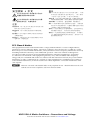
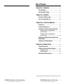
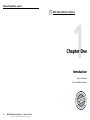
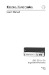
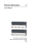
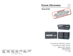
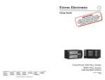
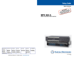
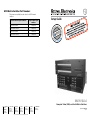
MVX Matrix Switcher Part Numbers
These items are included in each order for a MVX A matrix
switcher:
Matrix switcher part numbers
Replacement part
number
MVX 128 VGA A
60-799-01
MVX 1212 VGA A
60-858-01
MVX 168 VGA A
60-838-01
MVX 1616 VGA A
60-839-01
Setup Guide
MVX VGA A
Computer Video (VGA) and Audio Matrix Switchers
Extron USA - West
Headquarters
+800.633.9876
Inside USA / Canada Only
+1.714.491.1500
+1.714.491.1517 FAX
Extron USA - East
Extron Europe
Extron Asia
Extron Japan
Extron China
Extron Middle East
+800.633.9876
+800.3987.6673
+800.7339.8766
+81.3.3511.7655
+81.3.3511.7656 FAX
+400.883.1568
+971.4.2991800
+971.4.2991880 FAX
+1.919.863.1794
+1.919.863.1797 FAX
+31.33.453.4040
+31.33.453.4050 FAX
+65.6383.4400
+65.6383.4664 FAX
Inside USA / Canada Only
Inside Europe Only
Inside Asia Only
© 2009 Extron Electronics. All rights reserved.
Inside China Only
+86.21.3760.1568
+86.21.3760.1566 FAX
68-521-54 Rev. A
11 09
Precautions
Safety Instructions • English
This symbol is intended to alert the user of important
operating and maintenance (servicing) instructions in
the literature provided with the equipment.
This symbol is intended to alert the user of the
presence of uninsulated dangerous voltage within
the product’s enclosure that may present a risk of
electric shock.
Caution
Read Instructions • Read and understand all safety and operating
instructions before using the equipment.
Retain Instructions • The safety instructions should be kept for future
reference.
Follow Warnings • Follow all warnings and instructions marked on the
equipment or in the user information.
Avoid Attachments • Do not use tools or attachments that are not
recommended by the equipment manufacturer because they may be
hazardous.
Consignes de Sécurité • Français
Ce symbole sert à avertir l’utilisateur que la
documentation fournie avec le matériel contient des
instructions importantes concernant l’exploitation et
la maintenance (réparation).
Ce symbole sert à avertir l’utilisateur de la présence
dans le boîtier de l’appareil de  tensions dangereuses
non isolées posant des risques d’électrocution.
Attention
Lire les instructions• Prendre connaissance de toutes les consignes de
sécurité et d’exploitation avant d’utiliser le matériel.
Conserver les instructions• Ranger les consignes de sécurité afin de pouvoir
les consulter à l’avenir.
Respecter les avertissements • Observer tous les avertissements et consignes
marqués sur le matériel ou présentés dans la documentation utilisateur.
Eviter les pièces de fixation • Ne pas utiliser de pièces de fixation ni d’outils
non recommandés par le fabricant du matériel car cela risquerait de poser
certains dangers.
Sicherheitsanleitungen • Deutsch
Dieses Symbol soll dem Benutzer in der im
Lieferumfang enthaltenen Dokumentation
besonders wichtige Hinweise zur Bedienung und
Wartung (Instandhaltung) geben.
Dieses Symbol soll den Benutzer darauf aufmerksam
machen, daß im Inneren des Gehäuses dieses
Produktes gefährliche Spannungen, die nicht isoliert
sind und die einen elektrischen Schock verursachen
können, herrschen.
Achtung
Lesen der Anleitungen • Bevor Sie das Gerät zum ersten Mal verwenden,
sollten Sie alle Sicherheits-und Bedienungsanleitungen genau durchlesen
und verstehen.
Aufbewahren der Anleitungen • Die Hinweise zur elektrischen Sicherheit
des Produktes sollten Sie aufbewahren, damit Sie im Bedarfsfall darauf
zurückgreifen können.
Befolgen der Warnhinweise • Befolgen Sie alle Warnhinweise und
Anleitungen auf dem Gerät oder in der Benutzerdokumentation.
Keine Zusatzgeräte • Verwenden Sie keine Werkzeuge oder Zusatzgeräte,
die nicht ausdrücklich vom Hersteller empfohlen wurden, da diese eine
Gefahrenquelle darstellen können.
Instrucciones de seguridad • Español
Este símbolo se utiliza para advertir al usuario
sobre instrucciones importantes de operación y
mantenimiento (o cambio de partes) que se desean
destacar en el contenido de la documentación
suministrada con los equipos.
Este símbolo se utiliza para advertir al usuario sobre
la presencia de elementos con voltaje peligroso sin
protección aislante, que puedan encontrarse dentro
de la caja o alojamiento del producto, y que puedan
representar riesgo de electrocución.
Precaucion
Leer las instrucciones • Leer y analizar todas las instrucciones de operación y
seguridad, antes de usar el equipo.
Conservar las instrucciones • Conservar las instrucciones de seguridad para
futura consulta.
Obedecer las advertencias • Todas las advertencias e instrucciones marcadas
en el equipo o en la documentación del usuario, deben ser obedecidas.
Evitar el uso de accesorios • No usar herramientas o accesorios que no
sean especificamente recomendados por el fabricante, ya que podrian
implicar riesgos.
Warning
Power sources • This equipment should be operated only from the power source
indicated on the product. This equipment is intended to be used with a main power
system with a grounded (neutral) conductor. The third (grounding) pin is a safety
feature, do not attempt to bypass or disable it.
Power disconnection • To remove power from the equipment safely, remove all power
cords from the rear of the equipment, or the desktop power module (if detachable),
or from the power source receptacle (wall plug).
Power cord protection • Power cords should be routed so that they are not likely to be
stepped on or pinched by items placed upon or against them.
Servicing • Refer all servicing to qualified service personnel. There are no userserviceable parts inside. To prevent the risk of shock, do not attempt to service
this equipment yourself because opening or removing covers may expose you to
dangerous voltage or other hazards.
Slots and openings • If the equipment has slots or holes in the enclosure, these are
provided to prevent overheating of sensitive components inside. These openings
must never be blocked by other objects.
Lithium battery • There is a danger of explosion if battery is incorrectly
replaced. Replace it only with the same or equivalent type recommended by
the manufacturer. Dispose of used batteries according to the manufacturer’s
instructions.
Avertissement
Alimentations• Ne faire fonctionner ce matériel qu’avec la source d’alimentation
indiquée sur l’appareil. Ce matériel doit être utilisé avec une alimentation principale
comportant un fil de terre (neutre). Le troisième contact (de mise à la terre) constitue
un dispositif de sécurité : n’essayez pas de la contourner ni de la désactiver.
Déconnexion de l’alimentation• Pour mettre le matériel hors tension sans danger,
déconnectez tous les cordons d’alimentation de l’arrière de l’appareil ou du module
d’alimentation de bureau (s’il est amovible) ou encore de la prise secteur.
Protection du cordon d’alimentation • Acheminer les cordons d’alimentation de
manière à ce que personne ne risque de marcher dessus et à ce qu’ils ne soient pas
écrasés ou pincés par des objets.
Réparation-maintenance • Faire exécuter toutes les interventions de réparationmaintenance par un technicien qualifié. Aucun des éléments internes ne peut être
réparé par l’utilisateur. Afin d’éviter tout danger d’électrocution, l’utilisateur ne doit
pas essayer de procéder lui-même à ces opérations car l’ouverture ou le retrait des
couvercles risquent de l’exposer à de hautes tensions et autres dangers.
Fentes et orifices • Si le boîtier de l’appareil comporte des fentes ou des orifices, ceux-ci
servent à empêcher les composants internes sensibles de surchauffer. Ces ouvertures
ne doivent jamais être bloquées par des objets.
Lithium Batterie • Il a danger d’explosion s’ll y a remplacment incorrect de la batterie.
Remplacer uniquement avec une batterie du meme type ou d’un ype equivalent
recommande par le constructeur. Mettre au reut les batteries usagees conformement
aux instructions du fabricant.
Vorsicht
Stromquellen • Dieses Gerät sollte nur über die auf dem Produkt angegebene
Stromquelle betrieben werden. Dieses Gerät wurde für eine Verwendung mit einer
Hauptstromleitung mit einem geerdeten (neutralen) Leiter konzipiert. Der dritte
Kontakt ist für einen Erdanschluß, und stellt eine Sicherheitsfunktion dar. Diese
sollte nicht umgangen oder außer Betrieb gesetzt werden.
Stromunterbrechung • Um das Gerät auf sichere Weise vom Netz zu trennen, sollten
Sie alle Netzkabel aus der Rückseite des Gerätes, aus der externen Stomversorgung
(falls dies möglich ist) oder aus der Wandsteckdose ziehen.
Schutz des Netzkabels • Netzkabel sollten stets so verlegt werden, daß sie nicht im
Weg liegen und niemand darauf treten kann oder Objekte darauf- oder unmittelbar
dagegengestellt werden können.
Wartung • Alle Wartungsmaßnahmen sollten nur von qualifiziertem Servicepersonal
durchgeführt werden. Die internen Komponenten des Gerätes sind wartungsfrei.
Zur Vermeidung eines elektrischen Schocks versuchen Sie in keinem Fall, dieses
Gerät selbst öffnen, da beim Entfernen der Abdeckungen die Gefahr eines
elektrischen Schlags und/oder andere Gefahren bestehen.
Schlitze und Öffnungen • Wenn das Gerät Schlitze oder Löcher im Gehäuse aufweist,
dienen diese zur Vermeidung einer Überhitzung der empfindlichen Teile im
Inneren. Diese Öffnungen dürfen niemals von anderen Objekten blockiert werden.
Litium-Batterie • Explosionsgefahr, falls die Batterie nicht richtig ersetzt
wird. Ersetzen Sie verbrauchte Batterien nur durch den gleichen oder einen
vergleichbaren Batterietyp, der auch vom Hersteller empfohlen wird. Entsorgen Sie
verbrauchte Batterien bitte gemäß den Herstelleranweisungen.
Advertencia
Alimentación eléctrica • Este equipo debe conectarse únicamente a la fuente/tipo
de alimentación eléctrica indicada en el mismo. La alimentación eléctrica de este
equipo debe provenir de un sistema de distribución general con conductor neutro
a tierra. La tercera pata (puesta a tierra) es una medida de seguridad, no puentearia
ni eliminaria.
Desconexión de alimentación eléctrica • Para desconectar con seguridad la acometida
de alimentación eléctrica al equipo, desenchufar todos los cables de alimentación
en el panel trasero del equipo, o desenchufar el módulo de alimentación (si fuera
independiente), o desenchufar el cable del receptáculo de la pared.
Protección del cables de alimentación • Los cables de alimentación eléctrica se deben
instalar en lugares donde no sean pisados ni apretados por objetos que se puedan
apoyar sobre ellos.
Reparaciones/mantenimiento • Solicitar siempre los servicios técnicos de personal
calificado. En el interior no hay partes a las que el usuario deba acceder. Para evitar
riesgo de electrocución, no intentar personalmente la reparación/mantenimiento
de este equipo, ya que al abrir o extraer las tapas puede quedar expuesto a voltajes
peligrosos u otros riesgos.
Ranuras y aberturas • Si el equipo posee ranuras o orificios en su caja/alojamiento,
es para evitar el sobrecalientamiento de componentes internos sensibles. Estas
aberturas nunca se deben obstruir con otros objetos.
Batería de litio • Existe riesgo de explosión si esta batería se coloca en la posición
incorrecta. Cambiar esta batería únicamente con el mismo tipo (o su equivalente)
recomendado por el fabricante. Desachar las baterías usadas siguiendo las
instrucciones del fabricante.
Extron Warranty
Extron Electronics warrants this product against defects in materials and workmanship
for a period of three years from the date of purchase. In the event of malfunction during
the warranty period attributable directly to faulty workmanship and/or materials,
Extron Electronics will, at its option, repair or replace said products or components,
to whatever extent it shall deem necessary to restore said product to proper operating
condition, provided that it is returned within the warranty period, with proof of
purchase and description of malfunction to:
USA, Canada, South America,
and Central America:
Extron USA
1001 East Ball Road
Anaheim, CA 92805
U.S.A.
Europe, Africa, and the Middle East:
Extron Europe
Hanzeboulevard 10
3825 PH Amersfoort
The Netherlands
Asia:
Extron Asia
135 Joo Seng Road #04-01
PM Industrial Bldg.
Singapore 368363
Singapore
Japan:
Extron Japan
Kyodo Building, 16 Ichibancho
Chiyoda-ku, Tokyo 102-0082
Japan
China:
Extron China
686 Ronghua Road, Songjiang
District
Shanghai 201611
China
Middle East:
Extron Middle East
Dubai Airport Free Zone
F12, PO Box 293666
United Arab Emirates, Dubai
This Limited Warranty does not apply if the fault has been caused by misuse, improper
handling care, electrical or mechanical abuse, abnormal operating conditions or nonExtron authorized modification to the product.
If it has been determined that the product is defective, please call Extron and ask for an
Applications Engineer at (714) 491-1500 (USA), 31.33.453.4040 (Europe), 65.6383.4400
(Asia), or 81.3.3511.7655 (Japan) to receive an RA# (Return Authorization number). This
will begin the repair process as quickly as possible.
Units must be returned insured, with shipping charges prepaid. If not insured, you
assume the risk of loss or damage during shipment. Returned units must include the
serial number and a description of the problem, as well as the name of the person to
contact in case there are any questions.
Extron Electronics makes no further warranties either expressed or implied with respect
to the product and its quality, performance, merchantability, or fitness for any particular
use. In no event will Extron Electronics be liable for direct, indirect, or consequential
damages resulting from any defect in this product even if Extron Electronics has been
advised of such damage.
Please note that laws vary from state to state and country to country, and that some
provisions of this warranty may not apply to you.
安全须知 • 中文
警告
这个符号提示用户该设备用户手册中
有重要的操作和维护说明。
电源 • 该 设 备 只 能 使 用 产 品 上 标 明 的 电 源 。 设 备
必须使用有地线的供电系统供电。 第三条线
(地线)是安全设施,不能不用或跳过。
这个符号警告用户该设备机壳内有暴
拔掉电源 • 为安全地从设备拔掉电源,请拔掉所有设备后
或桌面电源的电源线,或任何接到市电系统的电源线。
露的危险电压,有触电危险。
电源线保护 • 妥善布线, 避免被踩踏,或重物挤压。
注意
阅读说明书 • 用 户 使 用 该 设 备 前 必 须 阅 读 并 理
解所有安全和使用说明。
保存说明书 • 用户应保存安全说明书以备将来使
用。
遵守警告 • 用户应遵守产品和用户指南上的所有安
全和操作说明。
维护 • 所有维修必须由认证的维修人员进行。 设备内部
没有用户可以更换的零件。为避免出现触电危险不要自
己试图打开设备盖子维修该设备。
通风孔 • 有些设备机壳上有通风槽或孔,它们是用来防止
机内敏感元件过热。 不要用任何东西挡住通风孔。
锂电池 • 不正确的更换电池会有爆炸的危险。 必须使用
与厂家推荐的相同或相近型号的电池。 按照生产厂的
建议处理废弃电池。
避免追加 • 不要使用该产品厂商没有推荐的工具或
追加设备,以避免危险。
FCC Class A Notice
This equipment has been tested and found to comply with the limits for a Class A digital device,
pursuant to part 15 of the FCC Rules. Operation is subject to the following two conditions: (1) this
device may not cause harmful interference, and (2) this device must accept any interference received,
including interference that may cause undesired operation. The Class A limits are designed to
provide reasonable protection against harmful interference when the equipment is operated in
a commercial environment. This equipment generates, uses, and can radiate radio frequency
energy and, if not installed and used in accordance with the instruction manual, may cause harmful
interference to radio communications. Operation of this equipment in a residential area is likely to
cause harmful interference, in which case the user will be required to correct the interference at his
own expense.
N
This unit was tested with shielded cables on the peripheral devices. Shielded cables must be used
with the unit to ensure compliance with FCC emissions limits.
MVX VGA A Matrix Switchers • Precautions and Listings
Refer also to the MVX VGA A User’s Manual at www.extron.com.
Table of Contents
Chapter One • Introduction..................................................... 1-1
About this Manual..................................................................... 1-2
About the Matrix Switchers................................................... 1-2
Chapter Two • Installation....................................................... 2-1
Rear Panel Installation Features............................................ 2-2
Front Panel Configuration Port. ............................................ 2-4
Chapter Three • Front Panel Operation.......................... 3-1
Creating a Tie............................................................................... 3-3
Saving or Recalling a Preset. .................................................. 3-4
Setting the Front Panel Locks (Executive Modes)........... 3-5
Selecting Lock mode 2 or toggling between
mode 2 and mode 0................................................................ 3-5
Selecting Lock mode 2 or toggling between
mode 2 and mode 1................................................................ 3-6
Viewing and Adjusting the Input Audio Level and
Output Volume. .......................................................................... 3-6
Viewing Ties (and Muting Outputs).................................... 3-7
Chapter Four • Remote Control............................................ 4-1
Selected SIS Commands........................................................... 4-2
Installing and Starting the Control Program..................... 4-7
Installing the program............................................................ 4-7
Starting the program.............................................................. 4-8
Button-Label Generator Program......................................... 4-9
All trademarks mentioned in this manual are the properties of their respective owners.
MVX VGA A Matrix Switchers • Precautions and Listings
Refer also to the MVX VGA A User’s Manual at www.extron.com.
MVX VGA A Matrix Switchers • Table of Contents
Refer also to the MVX VGA A User’s Manual at www.extron.com.
i
Table of Contents, cont’d
MVX VGA A Matrix Switchers
1
Chapter One
Introduction
About this Manual
About the Matrix Switchers
ii
MVX VGA A Matrix Switchers • Table of Contents
Refer also to the MVX VGA A User’s Manual at www.extron.com.
Introduction
N For more information on any subject in this guide, refer to
the MVX VGA A User’s Manual, available on the Extron
DVD or at www.extron.com.
About this Manual
This setup guide allows you to easily and quickly set up and
configure your matrix switcher. This guide also shows you how to:
•
•
Perform basic operations using the front panel controls
Perform basic operations using selected
Simple Instruction Set (SIS™) commands
Load and start up the Windows®-based Matrix Switchers
Control Program
•
About the Matrix Switchers
The Extron VGA matrix switchers covered in this manual
distribute any input to any combination of outputs. The
switchers can route multiple input/output combinations
simultaneously. The switchers are available in four matrix sizes
(the number of inputs and outputs):
•
•
•
•
MVX 128 VGA A
MVX 168 VGA A
MVX 1212 VGA A
MVX 1616 VGA A
(12 inputs by 8 outputs)
(16 inputs by 8 outputs)
(12 inputs by 12 outputs)
(16 inputs by 16 outputs)
Extron
VSC 500
Video Scan Converter
500
VSCERTER
CONV
SCAN
AX
MIN/M
SIZE
SIZE
Plasma
PAN/
TER/
CEN
NEXT
MENU
Plasma
E
FREEZT
RESE
IR
VCR
LCD
Projector
Audio In
Laptop
REMOTE
6
3
8
7
4
1
6
S
UT
TP
OU
2
RS232/RS422
8
5
5
4
3
11
2
1
12
9
12
TS
INPU
10
7
11
10
8
5
9
8
TS
6
3
INPU
7
Audio Out
Control System
6
4
1
RS-232
B
/B-Y
G
/Y
R
/R-Y
O
U
T
P
U
T
LAN
RESET
LINK
ACT
/VID
,Y,B-Y/YC
V
RGB/R-Y
H/
HV
R-Y
/C
Y
/VID
4
,Y,B-Y
SDI
RGB/R-Y
YC
.3A
100-240V
Extron
DVS 304
I
N
P
U
T
B-Y
VID
3
2
1
Extron
MVX Series
VGA and Audio
Matrix Switcher
5
4
2
3
ED
2
LIST3
1T2 .
U SI.T.E
C
1
Hz
50/60
Sound System
Digital Video Scaler
Audio In
DVD
1-2
PC
MVX VGA A Matrix Switchers • Introduction
Refer also to the MVX VGA A User’s Manual at www.extron.com.
2
Chapter Two
Installation
Rear Panel Installation Features
Front Panel Configuration Port
T
SE
RE
7
S
UT
TP
OU
MVX VGA A Matrix Switchers
Laptop
Installation
Rear Panel Installation Features
N The MVX VGA 128 A does not have the Sync Impedance
3
1
switches described below.
2
c
MVX 1616 VGA A
1
5
COMPUTER IN
13
9
COMPUTER OUT
9
13
6
10
14
3
7
11
15
4
8
12
16
1
5
2
A na he im, C A
6
14
10
®
3
7
11
15
4
8
12
16
US
LISTED
1T23
I.T.E.
SYNC IMPEDANCE
50
1
2
3
4
5
6
7
8
Each switch provides the option of selecting either 50 ohms or
75 ohms. The 50 ohms position is required only when a sync
problem is encountered. The normal position is 75 ohms.
RESET
2
75
1 2 3 4 5 6 7 8
OUTPUT
I
N
P
U
T
S
L
1
R
L
3
R
L
5
R
L
7
R
L
9
R
L
11 R
L
13 R
L
15 R
L
1
R
L
3
R
L
5
R
L
7
R
L
9
R
L
11 R
L
13 R
L
15 R
L
2
R
L
4
R
L
6
R
L
8
R
L
10 R
L
12 R
L
14 R
L
16 R
L
2
R
L
4
R
L
6
R
L
8
R
L
10 R
L
12 R
L
14 R
L
16 R
N An input producing an out-of-sync display — a display
O
U
T
P
U
T
S
REMOTE
50/60 Hz
that is rolling vertically and/or tearing horizontally —
could indicate an impedance problem.
RS-232/RS422
100-240V
Sync Impedence switches (168, 1212, and 1616 matrix sizes) —
The Sync Impedance switches compensate the output 1
through 8 impendance for different cable types and lengths. 1.2A MAX.
7
4
d
6
5
Tip
Sleeve
2
MVX 128 VGA A
3
5
7
9
11
1
3
5
7
2
4
6
8
10
12
2
4
6
8
RESET
1
2
3
4
5
6
OUTPUTS
7
8
9
10
11
12
1
2
3
4
5
6
7
8
REMOTE
INPUTS
1
RS232/RS422
LISTED
1T23
I.T.E.
Do not tin the wires!
e
Unbalanced Stereo Input
5
NO GROUND HERE.
6
NO GROUND HERE.
C Turn off power to the input and output devices, and
disconnect their power cords.
N The MVX matrix switchers can also switch component
video, S-video, or composite video with the appropriate
adapters.
a
b
Video inputs — Connect RGB video sources, as appropriate to
your switcher's video format and matrix size.
Do not tin the wires!
port — If desired, connect a control or computer to the
f Remote
rear panel Remote RS-232/RS-422 port.
N Remote port defaults: RS-232, 9600 baud, no parity, 8-bit,
1 stop bit, no flow control.
Video outputs — Connect RGB video displays, as appropriate
to your switcher's video format and matrix size.
video port that may require special commands to output
the video to that connector. Also, a laptop’s screen shuts
off once the external video port is activated. See the
computer’s user’s guide for details, or contact Extron for a
list of common laptop keyboard commands.
1
5
g
MVX VGA A Matrix Switchers • Installation
Refer also to the MVX VGA A User’s Manual at www.extron.com.
Balanced Stereo Output
CAUTION For unbalanced stereo audio, connect the sleeve(s) to the ground
contact. DO NOT connect the sleeve(s) to the negative (-) contacts.
N Most laptop or notebook computers have an external
2-2
Unbalanced Stereo Output
Tip
Ring
Sleeve(s)
Tip
Ring
R
Sleeve(s)
Tip
L
4
Balanced Stereo Input
Audio outputs — Connect audio devices to the 5-pole captive
screw connectors.
Tip
7
R
Tip
Sleeve
COMPUTER OUT
COMPUTER IN
Tip
Ring
Sleeve (s)
Tip
Ring
L
1
Audio inputs — Connect audio sources to the 5-pole captive
screw connectors.
Pin RS-232 Function RS-422 Function
1
— Not used
—
Not used
2
TX Transmit
TX– Transmit (–)
3
RX Receive
RX– Receive (–)
6
4
— Not used
—
Not used
5
Gnd Ground
Gnd Ground
9
6
— Not used
—
Not used
7
— Not used
RX+ Receive (+)
8
— Not used
TX+ Transmit (+)
9
— Not used
—
Not used
Power — Plug the switcher into a grounded AC source.
MVX VGA A Matrix Switchers • Installation
Refer also to the MVX VGA A User’s Manual at www.extron.com.
2-3
Installation, cont’d
Front Panel Configuration Port
CONTROL
ENTER
PRESET
IO
VIEW
ESC
RGBHV
AUDIO
CONFIG
MVX SERIES
VGA MATRIX SWITCHER WITH ADSP TM
8
h
Configuration port — If desired, connect a control or
computer to the front panel Configuration (RS-232) port.
Use an optional 9-pin D to 2.5 mm mini jack TRS RS-232
cable, part #70-335-01.
MVX VGA A Matrix Switchers
3
Chapter Three
Front Panel Operation
Creating a Tie
Saving or Recalling a Preset
Setting the Front Panel Locks (Executive Modes)
Viewing and Adjusting the Input Audio Level and Output Volume
Viewing Ties (and Muting Outputs)
2-4
MVX VGA A Matrix Switchers • Installation
Refer also to the MVX VGA A User’s Manual at www.extron.com.
Front Panel Operation
Creating a Tie
1.
INPUTS
1
2
3
4
5
6
7
8
9
10
11
12
13
14
15
16
CONTROL
1
2
3
4
5
6
7
8
9
10
11
12
13
14
15
16
ENTER
PRESET
VIEW
Press and release the Esc button to clear any button
indicators that may be lit.
I/O
ESC
VIDEO
Press the Esc button
to clear all selections.
AUDIO
CONFIG
OUTPUTS
MVX SERIES
VGA MATRIX SWITCHER WITH ADPS™
1
2
3 4 5 6
7 8
N On some MVX switchers, the video selection button is
labeled “RGBHV” rather than “Video”.
N The front panel controls and indicators have numerous
functions that are beyond the scope of this setup guide. Refer to the MVX VGA A Switcher User's Manual,
chapter 3, “Operation” for full details.
a
b
c
d
e
f
h
3-2
The LED blinks once.
2.
Press and release the Video and/or Audio I/O button(s) to
select or deselect video and/or audio as desired.
N Audio or video can be broken away (tied by itself) by
selecting only the Video button or only the Audio button.
I/O
Input buttons and LEDs — Buttons select inputs for front panel
operations. LEDs identify selected inputs and indicate other
miscellaneous displays.
Output buttons and LEDs — Buttons select outputs for front
panel operations. LEDs identify selected outputs and indicate
other miscellaneous displays.
Enter button and LED — Button saves changes that you make
on the front panel. LED indicates that a pending change needs
to be saved.
Preset button and LED — Button selects modes in which you
can save and recall presets. LED indicates the preset mode.
Lit when selected.
Off when deselected.
3.
Lit when selected.
Off when deselected.
VIDEO
AUDIO
Press and release the desired input button.
The input LED
lights to indicate
the selection.
5
4.
View (<) button and LED — Button selects a View mode, in
which you can view the current configuration without making
inadvertent changes and also mute and unmute outputs. Button
also can be used to decrease audio levels. LED identifies view
mode.
Esc (>) button and LED — Button cancels operations or
selections in progress and resets the front panel button indicators.
Button also can be used to increase audio level. LED flashes
once to indicate that the escape function has been activated.
g
ESC
Press and release the desired output button(s).
Output LEDs blink to indicate a potential tie.
3
5.
4
8
ENTER
Enter LED blinks to indicate the
need to confirm the change.
Press and release the Enter button. All button indicators
turn off.
Video button and LED — Button selects video for creation of
ties. LED indicates that video is selected for tie creation.
Audio button and LED — Button selects audio for creation
of ties. Button also selects Audio mode, in which you can
adjust audio levels. LED indicates that audio is selected for tie
creation. LED also indicates Audio mode is selected.
MVX VGA A Matrix Switchers • Front Panel Operation
Refer also to the MVX VGA A User’s Manual at www.extron.com.
MVX VGA A Matrix Switchers • Front Panel Operation
Refer also to the MVX VGA A User’s Manual at www.extron.com.
3-3
Front Panel Operation, cont’d
Saving or Recalling a Preset
Setting the Front Panel Locks (Executive Modes)
1.
Save a preset — Press and hold the Preset button until it
flashes.
Recall a preset — Press and release the Preset button.
Save a
preset
The matrix switcher has three levels of front panel security lock
that limit the operation of the switcher from the front panel. The
three levels are:
Press and hold.
2 seconds
Preset LED blinks.
PRESET
Recall a
preset
•
Lock mode 0 — The front panel is completely unlocked.
•
Lock mode 1 — All changes are locked from the front
panel (except for setting Lock mode 2). Some functions
can be viewed.
•
Lock mode 2 — Basic functions are unlocked. Advanced
features are locked and can be viewed only.
Basic features consist of:
PRESET
Press and release.
Preset LED lights.
PRESET
PRESET
m
Making ties
Saving and recalling presets
m Setting input audio gain and attenuation
m Changing Lock modes
m
All input and output buttons with assigned presets light.
The configuration data at assigned preset
locations will be overwritten.
1
2
3
4
5
Advanced features consist of:
m
m
2.
3.
N The switcher is shipped from the factory in Lock mode 2.
Press and release the desired input button.
1
N For a complete list of advanced features, refer to the
The LED blinks to indicate that this preset
is selected.
ENTER
The Enter LED
blinks to indicate
the need to save or
recall the preset.
Press and release the Enter button.
Setting video and audio output mutes
Setting audio output volume
MVX VGA A User’s Manual, available on the Extron
DVD or at www.extron.com.
Selecting Lock mode 2 or toggling between
mode 2 and mode 0
N If the switcher is in Lock mode 0 or mode 1, this procedure
selects mode 2.
If the switcher is in Lock mode 2, this action selects mode 0
(unlocks the switcher).
Toggle the lock on and off by pressing and holding the
Enter button, the Video button, and the Audio button for
approximately 2 seconds.
Press and hold the Enter, Video, and Audio
buttons simultaneously to turn on Lock mode 2
or to toggle between mode 2 and mode 0.
I/O
I/O
The Enter, Video, and
Audio LEDs blink twice to
indicate the mode change.
Release the buttons.
2 seconds
ENTER
3-4
MVX VGA A Matrix Switchers • Front Panel Operation
Refer also to the MVX VGA A User’s Manual at www.extron.com.
VIDEO
AUDIO
ENTER
VIDEO
AUDIO
MVX VGA A Matrix Switchers • Front Panel Operation
Refer also to the MVX VGA A User’s Manual at www.extron.com.
3-5
Front Panel Operation, cont’d
Viewing Ties (and Muting Outputs)
Selecting Lock mode 2 or toggling between
mode 2 and mode 1
1.
N If the switcher is in Lock mode 0 or mode 1, this procedure
Press the View button. Output LEDs light for outputs that
have no ties established.
selects mode 2.
N If an output LED blinks, that output is muted.
If the switcher is in Lock mode 2, this action selects mode 1.
2.
Press an input button. The LEDs for all tied outputs light.
Toggle the lock on and off by pressing and holding the Video
button and the Audio button for approximately 2 seconds.
3.
Press an output button. The LEDs for the tied input and
all tied outputs light.
Press and hold the Video and Audio buttons simultaneously to
turn on Lock mode 2 or to toggle between mode 2 and mode 1.
4.
If you want to toggle a mute on and off, press and hold
the output button for 2 seconds.
5.
Press the View button. All input and output LEDs return
to an unlit state.
I/O
I/O
The Video and Audio
LEDs blink twice to
indicate the mode change.
Release the buttons.
2 seconds
VIDEO
AUDIO
VIDEO
AUDIO
Viewing and Adjusting the Input Audio Level
and Output Volume
1.
Press and hold the Audio button until it flashes.
Audio LED blinks.
2.
AUDIO
Hold
2 seconds
AUDIO
Press an input button (for input level) or output button (for
volume). Refer to the MVX VGA A Switcher User's Manual,
chapter 3, “Operation”, to read the displayed value.
5
1
Press an input button to adjust gain/attenuation.
- or Press an output button to adjust the output volume.
2
3
4
OUTPUTS
3-6
Output LEDs display
gain/attenuation.
- or Input LEDs display
output volume level.
3.
Increase/decrease the level
or volume by pressing
the Esc (>) and View (<)
buttons.
4.
Press and release the Audio
button to exit.
button
decreases
the level.
button
increases
the level.
VIEW
ESC
MVX VGA A Matrix Switchers • Front Panel Operation
Refer also to the MVX VGA A User’s Manual at www.extron.com.
MVX VGA A Matrix Switchers • Front Panel Operation
Refer also to the MVX VGA A User’s Manual at www.extron.com.
3-7
Front Panel Operation, cont’d
MVX VGA A Matrix Switchers
4
Chapter Four
Remote Control
Selected SIS Commands
Installing and Starting the Control Program
Button Label Generator Program
3-8
MVX VGA A Matrix Switchers • Front Panel Operation
Refer also to the MVX VGA A User’s Manual at www.extron.com.
4-2
MVX VGA A Matrix Switchers • Remote Control
Refer also to the MVX VGA A User’s Manual at www.extron.com.
(host to switcher)
ASCII command
Response
(switcher to host)
Additional description
Refer also to the MVX VGA A User’s Manual at www.extron.com.
N
X! = Input number
X@ = Output number
Read audio output tie
Read video output tie
Read RGB output tie
Tie input X! to output X@, audio
Example:
Tie input X! to output X@, video
Example
(see 3rd Note, above)
Tie input X! to output X@, RGBHV
Example
(see 3rd Note, above):
Tie input 12 audio to output 4.
Out04•In12•Aud]
X!]
X!]
X!]
X@&
X@%
X@$
00 – (maximum number of inputs for your model) (00 = untie)
01 – (maximum number of outputs for your model)
Audio input X! is tied to output X@.
Video input X! is tied to output X@.
RGBHV input X! is tied to output X@.
Tie audio only (audio breakaway).
OutX@•InX!•Aud]
12*04$
Tie input 7 video to output 5.
X!*X@$
Tie video only (video breakaway).
OutX@•InX!•Vid]
10*4&
Out05•In07•Vid]
Tie input 10 RGB to output 4.
OutX@•InX!•RGB]
Out04•In10•RGB]
X!*X@&
7*5%
Tie input 1 video and audio to output 3.
Tie RGB only (video breakaway).
Out03•In01•All]
1*3!
X!*X@%
Tie input X!‘s video and audio to output X@.
OutX@•InX!•All]
X!*X@!
The switchers have Simple Instruction Set (SIS™) commands
that you can use for operation and configuration. You can run
these commands from a PC connected to either of the switcher’s
serial ports. See f (page 2-3) and h (page 2-4), for connection
information.
Tie input X! to output X@, video
and audio
Example:
N The & read tie command for RGB and the % read tie command for video can be used interchangeably.
N The & tie command for RGB and the % tie command for video can be used interchangeably.
N • Commands can be entered back-to-back in a string, with no spaces. For example: 1*1!02*02&003*003%4*8$.
• The matrix switchers support 1-, 2-, and 3-digit numeric entries (1*1!, 02*02&, or 003*003%).
N When you create a tie where X! = 00, you tie no input to the specified output (X@) (untie X@).
Create ties
Command
Remote Control
Selected SIS Commands
MVX VGA A Matrix Switchers • Remote Control
4-3
Command
ASCII command
(host to switcher)
Response
(switcher to host)
Additional description
Create ties
MVX VGA A Matrix Switchers • Remote Control
Refer also to the MVX VGA A User’s Manual at www.extron.com.
N • Commands can be entered back-to-back in a string, with no spaces. For example: 1*1!02*02&003*003%4*8$.
• The matrix switchers support 1-, 2-, and 3-digit numeric entries (1*1!, 02*02&, or 003*003%).
N When you create a tie where X! = 00, you tie no input to the specified output (X@) (untie X@).
N The & tie command for RGB and the % tie command for video can be used interchangeably.
N The & read tie command for RGB and the % read tie command for video can be used interchangeably.
Tie input X! to output X@, video
and audio
Example:
X!*X@!
OutX@•InX!•All]
Tie input X!‘s video and audio to output X@.
1*3!
Out03•In01•All]
Tie input X! to output X@, RGBHV
Example
(see 3rd Note, above):
X!*X@&
OutX@•InX!•RGB]
Tie input 1 video and audio to output 3.
Tie RGB only (video breakaway).
10*4&
Out04•In10•RGB]
Tie input 10 RGB to output 4.
Tie input X! to output X@, video
Example
(see 3rd Note, above)
X!*X@%
OutX@•InX!•Vid]
Tie video only (video breakaway).
7*5%
Out05•In07•Vid]
Tie input 7 video to output 5.
Tie input X! to output X@, audio
Example:
X!*X@$
OutX@•InX!•Aud]
Tie audio only (audio breakaway).
12*04$
Out04•In12•Aud]
Tie input 12 audio to output 4.
Read RGB output tie
X@&
X@%
X@$
X!]
X!]
X!]
RGBHV input X! is tied to output X@.
Read video output tie
Read audio output tie
N
X! = Input number
X@ = Output number
Video input X! is tied to output X@.
Audio input X! is tied to output X@.
00 – (maximum number of inputs for your model) (00 = untie)
01 – (maximum number of outputs for your model)
4-3
ASCII command
(host to switcher)
Response
(switcher to host)
Additional description
Video and audio mute commands
Refer also to the MVX VGA A User’s Manual at www.extron.com.
MVX VGA A Matrix Switchers • Remote Control
Read RGB/video mute
X@*1B
X@*0B
X@B
Global RGB/video mute
1*B
Global RGB/video unmute
0*B
Audio mute
Read audio mute
X@*1Z
X@*0Z
X@Z
Global audio mute
1*Z
Global audio unmute
0*Z
View output mutes
EVM}
X#]
Vmt1]
Vmt0]
AmtX@*1]
AmtX@*0]
X#]
Amt1]
Amt0]
X$1X$2X$3 ... X$n]
EVM}
Mut0220200000000000]
RGB/video mute
RGB/video unmute
Audio unmute
Example: MVX 1616 VGA A
VmtX@*1]
Mute output X@ RGB (video off).
VmtX@*0]
Unmute output X@ RGB (video on).
1 = mute on, 0 = mute off.
Mute all RGB outputs.
Unmute all RGB outputs.
Mute output X@ audio (audio off).
Unmute output X@ audio (audio on).
1 = mute on, 0 = mute off.
Mute all audio outputs.
Unmute all audio outputs.
Each X$ response is the mute status of an output,
starting from output 1.
n = the maximum number of outputs for this model.
Output 2, 3, and 5 audio is muted. All other
outputs are unmuted.
N The “Mut” portion of the response appears only when the switcher is in Verbose mode 3. See the Verbose mode command on page 4-6.
N
X@ = Output number
X# = Mute
X$ = Video/audio mute:
01 – (maximum number of outputs for your model)
0 = off (unmuted)
1 = on (muted)
0 = no mutes
2 = audio mute
1 = video mute
3 = video and audio mute
Command
ASCII command
Response
(host to switcher)
(switcher to host)
Set the audio volume to a specific
value
Example:
X@*X%V
OutX@•VolX%]
1*50v
Out01•Vol50]
Increment volume
X@+V
OutX@•VolX%]
Additional description
Audio output volume
MVX VGA A Matrix Switchers • Remote Control
Refer also to the MVX VGA A User’s Manual at www.extron.com.
Example:
Decrement volume
Read output volume
1+V
Out01•Vol51]
X@-V
X@V
OutX@•VolX%]
Set output 1 volume to an X% value of 50, an
attenuation of 14 dB (79% of total volume).
Increase volume by 1 step.
Decrease volume by 1 step.
X%]
Save and recall presets
N If you try to recall a preset that is not saved, the matrix switcher responds with the error code E11.
Save current configuration as a
Command character is a comma.
SprX^]
X^,
global preset
Example:
Save current ties as preset 9.
Spr09]
9,
Recall a global preset
Example:
N
X@ = Output number
X% = Volume
X^ = Preset number
X^.
5.
RprX^]
Command character is a period.
Rpr05]
Recall preset 5, which becomes the current
configuration.
01 – (maximum number of outputs for your model)
0 – 64 (1 dB/step except for 0-to-1, which is 22 dB) (default = 64 [0 dB])
01 - 32
Remote Control, cont’d
4-4
Command
4-5
ASCII command
(host to switcher)
Response
(switcher to host)
Additional description
Lock (executive) modes
Refer also to the MVX VGA A User’s Manual at www.extron.com.
MVX VGA A Matrix Switchers • Remote Control
N See “Setting the front panel locks (Executive modes)” on page 3-4 for more information on the Lock modes.
Lock all front panel functions
1X
Enable Lock mode 1.
Exe1]
Lock advanced front panel functions
2X
Exe2]
Enable Lock mode 2.
Unlock all front panel functions
0X
Exe0]
Enable Lock mode 0.
View lock status
X
X&]
Information requests
Information request
I
VX*XX(•AX*XX(]
Request part number
N
Query controller firmware version
Q
Q
X1)]
X1!]
1.23]
EX1@CV}
ECV}
VrbX1@]
X1@]
Example:
VX*XX( = video size, AX*XX( = audio size
The factory-installed controller firmware version
is 1.23 (sample value only).
Verbose mode
Set verbose mode
Read verbose mode
N
X& = Lock mode
0, 1, or 2
X* = Inputs
Total number of inputs for this switcher
X( = Outputs
Total number of outputs for this switcher
X1) = Part number
See the MVX VGA A User’s Manual, for a complete list of part numbers.
X1! = Firmware version number to second decimal place (x.xx)
X1@ = Verbose mode
0 = clear/none (default for Telnet connection)
1 = verbose mode (RS-232/RS-422 default)
2 = tagged responses for queries
3 = verbose mode and tagged for queries
Remote Control, cont’d
4-6
Command
4-6
(host to switcher)
ASCII command
Response
(switcher to host)
Additional description
N
VrbX1@]
X1@]
EX1@CV}
ECV}
Q
Q
X1)]
X1!]
1.23]
VX*XX(•AX*XX(]
The factory-installed controller firmware version
is 1.23 (sample value only).
VX*XX( = video size, AX*XX( = audio size
Enable Lock mode 0.
Exe0]
X&]
Enable Lock mode 2.
Exe2]
N
I
X
0X
2X
MVX VGA A Matrix Switchers • Remote Control
Refer also to the MVX VGA A User’s Manual at www.extron.com.
X1@ = Verbose mode
0 = clear/none (default for Telnet connection)
1 = verbose mode (RS-232/RS-422 default)
2 = tagged responses for queries
3 = verbose mode and tagged for queries
X& = Lock mode
0, 1, or 2
X* = Inputs
Total number of inputs for this switcher
X( = Outputs
Total number of outputs for this switcher
X1) = Part number
See the MVX VGA A User’s Manual, for a complete list of part numbers.
X1! = Firmware version number to second decimal place (x.xx)
Read verbose mode
Set verbose mode
Verbose mode
Example:
Query controller firmware version
Request part number
Information request
Information requests
View lock status
Unlock all front panel functions
Lock advanced front panel functions
N See “Setting the front panel locks (Executive modes)” on page 3-4 for more information on the Lock modes.
Lock all front panel functions
1X
Enable Lock mode 1.
Exe1]
Lock (executive) modes
Command
Remote Control, cont’d
Installing and Starting the Control Program
Another way to operate the switcher is via the Windows®-based
Matrix Switchers Control Program. This program is contained
on the Extron Software Products DVD (included with the
switcher). Run this program on a PC connected to either of the
switcher’s serial ports. See f (page 2-3) and h (page 2-4), for
connection information.The program must be installed on a
Windows-based computer and cannot be run from the DVD.
N For details on operating the program, refer to the
MVX VGA A Switcher User's Manual, chapter 5,
“Matrix Software”.
Installing the program
1.
Insert the disk into the drive. The Extron software DVD
window should appear automatically.
N If the window does not self-start, run Launch.exe from the
DVD.
2.
Click the Software tab.
3.
Scroll to the Matrix Switchers program and click Install.
Refer also to the MVX VGA A User’s Manual at www.extron.com.
MVX VGA A Matrix Switchers • Remote Control
4-7
Remote Control, cont’d
4.
Follow the on-screen instructions. The installation
program creates a C:\Program Files\Extron\
Matrix_Switchers directory and an “Extron Electronics\
Matrix Switchers” group folder. It installs the following
four programs:
•
•
•
•
MATRIX Switcher+ Control Program
MATRIX Switcher+ Help
Uninstall MATRIX Switcher
Check for Matrix Updates
Starting the program
1.
Click Start > Programs > Extron Electronics > Matrix
Switchers > MATRIX Switcher + Control Pgm.
The Comm Port Selection window appears.
Button-Label Generator Program
The Button Label Generator software creates labels that you can
place in the translucent covers above and below the front panel
input and output buttons. You can create labels with names,
alphanumeric characters, or even color bitmaps for easy and
intuitive input and output selection.
The Extron Button Label Generator is available on the Extron
Web site, www.extron.com, under the Download Center tab
and on the Extron Software Products DVD that accompanies the
switcher.
Refer to the MVX VGA A Switcher User's Manual, chapter 5,
“Matrix Software”, for operating the Button Label Generator
program and appendix A, “Specifications, Part Numbers,
Accessories”, for the procedure for removing and replacing the
translucent covers.
2.
Choose the comm (serial) port that is connected to the
switcher.
N Check the baud rate displayed in the
comm port selection window. If you
need to change the baud rate, click
the Baud button and double-click
the desired baud rate.
4-8
Click OK.
The Matrix Switchers Control Program is ready for
operation.
MVX VGA A Matrix Switchers • Remote Control
Refer also to the MVX VGA A User’s Manual at www.extron.com.
MVX VGA A Matrix Switchers • Remote Control
Refer also to the MVX VGA A User’s Manual at www.extron.com.
4-9
Remote Control, cont’d
4-10
MVX VGA A Matrix Switchers • Remote Control
Refer also to the MVX VGA A User’s Manual at www.extron.com.