1
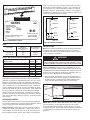
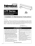
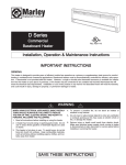
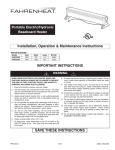
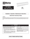
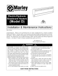
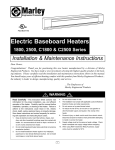
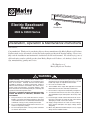
Electric Baseboard
Heaters
File #E37116
2500 & C2500 Series
Installation, Operation & Maintenance Instructions
Dear Owner,
Congratulations! Thank you for purchasing this new heater manufactured by Marley Engineered Products.
You have made a wise investment selecting the highest quality product in the heating industry. Please carefully read the installation and maintenance instructions shown in this manual. You should enjoy years of
efficient heating comfort with this product from Marley Engineered Products... the industry’s leader in design, manufacturing, quality and service.
... The Employees of
Marley Engineered Products
!
WARNING
Read Carefully - This Instruction Sheet contains vital information for the proper installation, use, and efficient operation of the heater. Carefully read the manual before
installation, operation, or cleaning of the heater. Failure to
adhere to the instructions could result in fire, electric shock,
death, serious personal injury, or property damage. Save
these instructions and review frequently for continuing safe
operation and instructing future users.
CAUTION - TO REDUCE RISK OF FIRE AND ELECTRIC
SHOCK OR INJURY TO PERSONS, OBSERVE THE
FOLLOWING:
1. Keep all electrical cords, foam filled articles, drapes,
bedding, and other household furnishings away from
contact with heater. It is recommended all items be kept
a minimum of six (6") inches (152mm) from heater.
2. Do not install baseboard heater below electrical convenience receptacles (outlets).
3. Do not install upside down or in any position other than
as shown in this manual.
4. Do not install baseboard heater against vinyl wallpaper,
paperboard or low density fiberboard surface. Do not
install vinyl drapes or vinyl blinds above heater.
5. Do not recess heater in wall.
6. The installation must comply with applicable Local and
National Electrical Codes and utility requirements.
7. Do not remove or by-pass the safety limit (see Figure 4).
8. To reduce the risk of fire, do not store or use gasoline or
other flammable vapors and liquids in the vicinity of the
heater.
9. Personal injury or death could result from electric shock.
Disconnect all power to heater at main panel before
attempting to install or service this heater.
10. Supply voltage must be the same as heater voltage.
Check heater nameplate and supply voltage before
energizing.
11. When using RSA Transformer Relay Accessory, supply
wiring must be suitable for 90°C.
mum of 2 in.(51mm) air space between heater front and nearest
drape fold as shown in Example 1 Figure 2, or 6 in.(153mm) airspace between top of heater and bottom of drapes as shown in
Example 2, Figure 2. Allow minimum clearance of 1 in. (26mm)
from drapes to ceiling and to top of floor covering to permit air circulation as shown in Example 1, Figure 2.
CEILING
NAMEPLATE
2543NWC
1007
DATE CODE
BASEBOARD HEATER
PLINTHE CHAUFFANTE
VOLTS AC
60HZ
WATTS
3.1/2.7
AMPS
750/546
MARLEY ENGINEERED PRODUCTS
BENNETTSVILLE, SC 29512
Total Amps
0 thru 12
12.1 thru 16
16.1 thru 24
54E1 LISTED
BASEBOARD HEATER
Example 2
DRAPES
Minimum
AWG. Wire Size
(Copper)
#14
#12
#10
DESCRIPTION
Heater Only (Each Wiring Compartment)
Heater W/SP Thermostat
Heater W/DP Thermostat
Heater W/Heat-Cool Switch Receptacle
Heater W/Duplex Receptacle
Heater W/DP Disconnect Switch
Heater W/Power Relay
Heater W/Transformer Relay
MIN. 6”
(152 mm)
MIN. 2”
(51 mm)
PATENT PENDING
4104-2109-265
HEATER
HEATER
FLOOR
FLOOR
MIN. 1”
(25 mm)
Figure 2: Clearance for Drapery
Circuit Breaker
or Fuse Size
Table 2: Net Volumes of Wiring Compartment
GENERAL
Example 1
DRAPES
Figure 1: Nameplate Location
Table 1
MIN. 1”
(25 mm)
WALL
240/208
MIN. 1”
(25 mm)
WALL
MODEL NO.
CEILING
15 amp
20 amp
30 amp
CUBIC
INCHES
14.96
11.18
11.18
9.51
11.18
11.18
10.76
2.93
CUBIC
CM
241
180
180
153
180
180
174
47
This heater is designed to provide years of efficient, trouble free
operation as a primary or supplementary heat source for comfort
heating in residential and commercial applications. Baseboard
heaters must be thermostatically controlled for efficient, safe operation. A thermostat is not provided with this heater. However, a
single or double pole thermostat accessory is available for installation into this heater at your place of purchase, or the heater may
be connected to any suitable wall mounted thermostat that will
meet the electrical load requirements. Installation or use of this
product in any manner not described herein will void the warranty
and could result in injury, damage to property, or permanent damage to heater.
UNPACKING HEATER
Check heater to make sure it has not been damaged in shipping.
Do not install or attempt to operate the heater if damaged. Return
to place of purchase or file claim with freight carrier.
Notice to owners: Certain fabrics discolor in time from indirect
sunlight and normal room temperature - mostly organic and synthetic material. They will discolor more rapidly when exposed to
direct sunlight and warm currents. Hang drapes to provide mini-
INSTALLATION
Note: Check heater nameplate for electrical ratings before beginning. Make sure voltage and amperage ratings on the heater
nameplate match those of the power supply and any accessories
used, see Figure 1 and Table 1.
!
WARNING
NEVER CONNECT A HEATER TO A VOLTAGE GREATER
THAN THE NAMEPLATE RATED VOLTAGE (FIGURE 1). TO DO
SO WILL DAMAGE THE HEATER AND COULD CAUSE A FIRE
Floors & Carpeting: Heaters may be mounted directly on any
floor surface, including carpeting. Where wall-to-wall carpets are
installed after the baseboard installation, the carpeting can be run
up to the front and around the heater body, providing it does not
obstruct air flow. (Maximum 3/4” (19mm) thick).
1. Remove wiring compartment cover at end of heater where
power supply cable is to enter (Figure 3). Determine desired
mounting location, position heater to wall and mark wall (or
floor) at location where power supply is to enter heater.
Wiring
compartment
cover
Screw
Figure 3
NOTE: Make sure the caution label with the word “TOP” is at the
top of the heater. For most efficient operation locate heaters
along outside wall under windows. Position heater so it can be
secured to wall stud. Power cable must enter heater through built
in cable clamp or one of the knockouts provided in wiring compartment.
2. Drill hole in wall (or floor) at desired location for power supply
entry. Install power supply wiring to heater and thermostat location as determined by thermostat option selected. Allow approximately 10 to 12in (254mm to 305mm) of wire at heater for
connections.
3. If any accessories are to be used with this heater, refer to installation instructions provided with the accessory for proper
installation and wiring. Visit www.marleymep.com for instructions on some common accessories.
4. Wireway Cover - Commercial Baseboard Only
a. The wireway cover is a factory installed feature of Marley
commercial baseboard heaters. Two cables or four individual conductors plus two ground wires may be routed
through the wireway. Refer to page 2, Table 1 for wire size
and current loads.
!
CAUTION
WHEN USING BOTTOM MOUNTING HOLES, (TO PREVENT
A POSSIBLE SHOCK OR FIRE HAZARD,) MAKE SURE YOU
DO NOT DRIVE THE SCREWS THROUGH OR DAMAGE THE
POWER SUPPLY WIRE.
7. Connect the supply cable grounding wire to the bare copper
pigtail in wiring compartment.
8. After making sure the electrical power coming to the heater is
turned off at main switch panel follow the desired wiring diagram, as shown in Figure 5, to connect the power supply to
the heater using approved wire nuts.
!
WARNING
TO PREVENT A POSSIBLE FIRE, MAKE SURE ALL WIRE
CONNECTIONS ARE TIGHT.
b. To gain access to wireway, lay heater face down and remove the screws holding the wireway from the back of the
heater. Remove the knockouts in the channel areas of both
terminal boxes.
NOTE: When accessories are installed, use wiring diagram
supplied with the accessory.
d. Wire heater according to wiring diagrams in Figure 5. Reattach the wireway cover using the screws.
10.Replace wiring compartment cover.
c. Insert the plastic bushings from the parts kit (in wiring compartment) in the knockout holes.
Mounting perforations
Safety limit
DO NOT
BYPASS
Built in cable clamp
Capillary tube
Bottom mounting holes
Figure 4: Left Side Wiring Compartment Shown
5. Loosen screw in built-in cable clamp (Figure 4) or remove desired knockout from heater wiring compartment. Install power
cable into wiring compartment allowing at least 6 in (153mm)
of cable for connection to heater. To install two power cables
using the built-in cable clamp, bend tab covering second hole
up and back to rear wall of wiring compartment. If built-in
cable clamp is not used, install approved cable restraint (not
included ) in desired knockout.
6. Position heater at desired location and attach to wall using
wood screws or appropriate hardware.
Note: cross stamped mounting perforations are provided in back
of heater enclosure above heating element at mounting screw locations, see Figure 4.
Locate studs and drive screws into studs where possible. For
heaters up to 6 feet (1.8 m) in length, one screw at each end is
adequate. For longer units, an additional screw in center is required. Tighten screws and then loosen screws at least ¼ turn
to allow heater to expand and contract during use. If unit is
mounted above floor, two additional mounting holes are supplied at each end below the heating element (see Figure 4).
Install an additional screw at each end for stability making sure
to loosen each screw at least ¼ turn.
9. If front cover was removed, reinstall by hooking the top edge
on the support bracket(s). Then push down to latch onto the
support bracket(s).
11.Follow instructions accompanying thermostat for installation
and wiring thermostat. Visit www.marleymep.com for typical
thermostat wiring diagrams.
OPERATION
1. After the baseboard system has been completely installed, all
thermostats should be turned to LOW or NO HEAT. Then turn
on breakers. Wait 3 to 5 minutes and check to see that none
of the heaters are operating. If operating, disconnect power
and check wiring. If none are operating then turn thermostats
to highest position and wait 3 to 5 minutes. Check to see that
all heater(s) are operating. Should any not be operating, disconnect power and check wiring.
2. Allow entire system to operate steadily for 1/2 hour. This
should remove oily residue from manufacturing. (Some
smoking may occur).
3. Select the setting for comfort on all thermostats.
CLEANING
Because of the convection heating principle which depends on air
circulation through the finned element, dust will collect between
the fins. The heater should be cleaned regularly for maximum efficiency. Before cleaning be sure the heater is off and the element is cool. A vacuum cleaner with a brush attachment may be
used for cleaning. The finish of the heater may be cleaned with a
slightly damp rag if desired.
PAINTING
Painting of this baseboard is not necessary unless to match room
decor. To paint, first rough up the exterior with steel wool. Paint
only the exterior of the cabinet. Do not allow paint on the element
and safety limit capillary tube (Figure 4). Use a high quality
enamel paint.
Factory Wiring Shown
SAFETY
LIMIT
Safety limit in left side
DO NOT BYPASS
WHITE OR BLACK
L2
Orange wire nut
(Disconnect for left
side supply wiring)
L1
**
ELEMENT
*
L1
L2
*
Heater element leads are color coded by voltage* Note: Yellow
120V
GROUND
Right End Supply Wiring
E
ELEMENT
L1
GRND
L2
208V
240V
277V
WHITE OR BLACK
L2
L1
L2
SAFETY
LIMIT
WHITE OR BLACK
ELEMENT
L2
L1
G
FACTORY WIRING
FIELD WIRING
L2
L1
GROUND
L1
FACTORY WIRING
FIELD WIRING
GROUND
Connection For Adjacent Heaters
SAFETY
LIMIT
for 120V & 277V
** Note: White
Black for all others
GROUND
Blue
Red
Brown
Left End Supply Wiring
SAFETY
LIMIT
Orange wire nut
(Disconnect for right
side supply wiring)
SAFETY
LIMIT
WHITE OR BLACK
GRND
L1
L2
WHITE OR BLACK
L2
E
L2
ELEMENT
L1
L1
GROUND
FACTORY WIRING
FIELD WIRING
Figure 5: Wiring Diagrams
L1
GRND
F
L1
L2
ELEMENT
L2
L1
GROUND
L2
GROUND
L
LIMITED WARRANTY
All products manufactured by Marley Engineered Products are warranted against defects in workmanship and materials for one year from date of installation, except heating elements which are warranted against defects in workmanship and materials for ten years from date of installation. This warranty does not apply to damage from accident, misuse, or alteration; nor where the connected voltage is more than 5% above the nameplate voltage;
nor to equipment improperly installed or wired or maintained in violation of the product’s installation instructions. All claims for warranty work must be accompanied by proof of the date of installation.
L
The customer shall be responsible for all costs incurred in the removal or reinstallation of products, including labor costs, and shipping costs incurred to
return products to Marley Engineered Products Service Center. Within the limitations of this warranty, inoperative units should be returned to the nearest Marley authorized service center or the Marley Engineered Products Service Center, and we will repair or replace, at our option, at no charge to you
with return freight paid by Marley. It is agreed that such repair or replacement is the exclusive remedy available from Marley Engineered Products.
THE ABOVE WARRANTIES ARE IN LIEU OF ALL OTHER WARRANTIES EXPRESSED OR IMPLIED, AND ALL IMPLIED WARRANTIES OF MERCHANTABILITY AND FITNESS FOR A PARTICULAR PURPOSE WHICH EXCEED THE AFORESAID EXPRESSED WARRANTIES ARE HEREBY DISCLAIMED AND EXCLUDED FROM THIS AGREEMENT. MARLEY ENGINEERED PRODUCTS SHALL NOT BE LIABLE FOR CONSEQUENTIAL
DAMAGES ARISING WITH RESPECT TO THE PRODUCT, WHETHER BASED UPON NEGLIGENCE, TORT, STRICT LIABILITY, OR CONTRACT.
Some states do not allow the exclusion or limitation of incidental or consequential damages, so the above exclusion or limitation may not apply to you.
This warranty gives you specific legal rights, and you may also have other rights which vary from state to state.
For the address of your nearest authorized service center, contact Marley Engineered Products in Bennettsville, SC, at 1-800-642-4328. Merchandise
returned to the factory must be accompanied by a return authorization and service identification tag, both available from Marley Engineered Products.
When requesting return authorization, include all catalog numbers shown on the products.
HOW TO OBTAIN WARRANTY SERVICE AND
WARRANTY PARTS PLUS GENERAL INFORMATION
1. Warranty Service or Parts
2. Purchase Replacement Parts
3. General Product Information
1-800-642-4328
1-800-654-3545
www.marleymep.com
Note: When obtaining service always have the following:
1. Model number of the product
2. Date of manufacture
3. Part number or description
470 Beauty Spot Rd. East
Bennettsville, SC 29512 USA
Part No. 5200-2194-008
ECR 36976
10/07