1
Remote SAFEPATH
Operation and Installation
Manual
Models:
RSAPE-B
RSAPE-R
273 Branchport Avenue
Long Branch, NJ 07740
Telephone: 800-631-2148
Fax: 732-222-8707
www.wheelockinc.com
Part Number A83666 Revision A
Thank you for using our products. Use this product according to this instruction manual. Please keep
this instruction manual for future reference.
ANY MATERIAL EXTRAPOLATED FROM THIS DOCUMENT OR FROM WHEELOCK MANUALS OR OTHER DOCUMENTS
DESCRIBING THE PRODUCT FOR USE IN PROMOTIONAL OR ADVERTISING CLAIMS, OR FOR ANY OTHER USE,
INCLUDING DESCRIPTION OF THE PRODUCT'S APPLICATION, OPERATION, INSTALLATION AND TESTING IS USED AT
THE SOLE RISK OF THE USER AND WHEELOCK WILL NOT HAVE ANY LIABILITY FOR SUCH USE.
Remote SAFEPATH Manual
Rev. C December 1998
Sheet 1 of 50
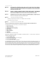
Conventions Used in This Manual
This manual uses the following conventions for notes, cautions, and warnings.
NOTE: All CAUTIONS and WARNINGS are identified by the symbol
.
All warnings are printed in bold capital letters.
CAUTION:
Indicates a potentially hazardous situation which, if not avoided, could result in minor or moderate injury. It may
also be used to alert against unsafe practices.
WARNING:
INDICATES A POTENTIALLY HAZARDOUS SITUATION WHICH, IF NOT AVOIDED, COULD RESULT IN
PROPERTY DAMAGE AND SERIOUS PERSONAL INJURY OR DEATH TO YOU AND OR OTHERS.
Copyright 1998 Wheelock, Inc. All rights reserved.
P83665
Remote SAFEPATH Manual
Rev. C December 1998
Remote SAFEPATH Manual
Rev. C December 1998
Sheet 2 of 50
Preface
The Remote SAFEPATH panel provides remote amplification and live announcement capabilities. Live announcements can be
made at either the central or remote location. Pre-recorded messages, however, can only be initiated from the central SAFEPATH
panel.
This panel does not sense an emergency condition or hazardous fires; it is only a part of a system that does sense such conditions.
The Remote SAFEPATH panel, when activated by a central SAFEPATH panel, provides a pre-recorded tone and/or voice
message(s) to notification appliances. When used as part of a protective signaling system, the Remote SAFEPATH panel must be
properly connected to a central SAFEPATH panel and to LISTED compatible notification appliances for proper operation.
PERSONNEL PROPERLY QUALIFIED IN THE APPLICATION AND USE OF LIFE SAFETY EQUIPMENT MUST READ THIS
MANUAL CAREFULLY BEFORE PERFORMING ACTIONS TO SPECIFY, APPLY, INSTALL, MAINTAIN AND OPERATIONALLY
TEST SAFEPATH PRODUCTS IN ACCORDANCE WITH THE INSTRUCTIONS IN THIS MANUAL.
WARNING:
•
•
•
IF SAFETY PRECAUTIONS, INSTALLATION AND TESTING INSTRUCTIONS ARE NOT PERFORMED
PROPERLY, THIS SAFEPATH PANEL MAY NOT OPERATE IN AN EMERGENCY SITUATION WHICH
COULD RESULT IN PROPERTY DAMAGE AND SERIOUS INJURY OR DEATH TO YOU AND/OR OTHERS.
DO NOT assume any installation, operation and testing details not shown in this manual.
This SAFEPATH panel should only be operated with covers properly in place.
KEEP THIS MANUAL WITH THIS PANEL FOR FUTURE REFERENCE for the life of the system and make it available to all
qualified personnel who operate, test, maintain, or service this product. We strongly recommend that such personnel read and
understand this manual and all other relevant product instructions.
This panel WILL NOT WORK WITHOUT POWER. This panel is powered by 120VAC. Back-up power is provided by 24VDC
batteries. If both sources of power are cut off for any reason, the SAFEPATH panel will not provide the desired tone and/or voice
warning.
WHEELOCK EXPRESSLY DISCLAIMS ALL LIABILITY FOR THE CONTENT, CLARITY AND LANGUAGES OF, AND OUTPUT
CHANNEL AND PRIORITY LEVEL ASSIGNED TO, ANY AND ALL MESSAGES. IT IS ESSENTIAL THAT YOU HAVE MESSAGE
CONTENT AND LANGUAGE, SEQUENCE, OUTPUT CHANNEL AND PRIORITY ASSIGNMENTS REVIEWED AND APPROVED
BY QUALIFIED LEGAL AND SAFETY ADVISORS, QUALIFIED REPRESENTATIVE(S) OF OWNER(S) AND USER(S), AND
AUTHORITIES HAVING JURISDICTION.
CAUTION: This panel’s printed circuit boards are sensitive to static electricity and have delicate components mounted on them.
Before handling either a board or any component on a board, discharge any static electricity from your body by touching a grounded
object such as a metal screw which is connected to earth ground. Handle the board by its edges, and be careful not to twist or flex
it. This panel is to be installed in a static free area and the user is to properly attach grounded wrist straps before touching any static
sensitive areas. After handling this panel’s printed circuit boards, the panel should be tested in accordance with the “System
Checkout” guidelines in the “Installation” section of this manual to verify that the printed circuit boards are undamaged and
functioning properly.
COMPLY WITH ALL OF THE LATEST APPLICABLE CODES, REGULATIONS, LAWS, STANDARDS, GUIDELINES.
For emergency, hazardous, security, life safety and fire protective signaling system applications, the SAFEPATH products must be
used within their published specifications and only with a LISTED compatible control panel in accordance with sound engineering
judgment and the instructions of the manufacturer and in accordance with local, state and federal codes, regulations and laws.
SAFEPATH products must be PROPERLY specified, applied, installed, operated, maintained and operationally tested in accordance
with these instructions at the time of installation and at least twice a year or more often as required by local, state and federal codes,
regulations and laws. Installation, testing and maintenance must be performed by qualified personnel for proper operation in
accordance with all of the latest National Fire Protection Association (NFPA), Underwriters' Laboratories (UL), National Electrical
Code (NEC), Occupational Safety and Health Administration (OSHA), local, state, county, province, district, federal and other
applicable building and fire standards, guidelines, regulations, laws and codes including, but not limited to, all appendices and
amendments and the requirements of the local authority having jurisdiction (AHJ).
WARNING:
IF THE PROTECTIVE SIGNALING SYSTEM SOUNDS AND/OR FLASHES, IT IS A WARNING OF A
POSSIBLY SERIOUS SITUATION AND REQUIRES YOUR IMMEDIATE ATTENTION.
Remote SAFEPATH Manual
Rev. C December 1998
Sheet 3 of 50
NOTE: This equipment has been tested and found to comply with the limits for a Class A digital device, pursuant to Part 15 of the
FCC Rules. These limits are designed to provide reasonable protection against harmful interference when the equipment is
operated in a commercial environment. This equipment generates, uses, and can radiate radio frequency energy and, if not
installed and used in accordance with the instruction manual, may cause harmful interference to radio communications. Operation
of this equipment in a residential area is likely to cause harmful interference in which case the user will be required to correct the
interference at his own expense.
Request that the local authority having jurisdiction inspect the proposed placement of the notification appliances and receive their
approval.
The output of the audio system may not be heard in all cases. Sound can be blocked or reduced by walls, doors, carpeting, wall
covering, furniture, insulation, bed coverings, and other obstacles that may temporarily or permanently impede the output of the
audio system. Sound is also reduced by distance and masked by background noise. The output of the audio system may not be
sufficient to alert all occupants, especially those who are asleep, those who are hearing-impaired, those who are wearing devices
that plug or cover the ears, and those who have recently used drugs or alcohol. The output of the audio system may not be heard
by an alert person if the output device is placed in an area which is isolated by a closed door, or is located on a different floor from
the person in a hazardous situation or is placed too far away to be heard over ambient noise such as, but not limited to, running
water, traffic, air conditioners, machinery or musical appliances.
WARNING:
AUDIBLE SIGNALS MAY MASK MEDICAL EQUIPMENT MONITORING ALARMS. WHERE MEDICAL
EQUIPMENT MONITORING ALARMS ARE IN USE, DO NOT USE AUDIBLE SIGNALS; PROVIDE VISUAL
NOTIFICATION APPLIANCES IN HIGHLY VISIBLE LOCATIONS.
If audible tones and/or voice messages cannot be readily heard and understood clearly within the protected areas as intended, it is
necessary to increase the number and/or sound output intensity of speakers within those areas so that they are heard and
understood clearly when activated.
Notification equipment cannot last forever. Even though this panel is expected to last up to ten years, any of its parts or components
could fail before then. Therefore testing of the entire protective signaling system, including this panel, all notification equipment, as
well as all messages and their output channel, and priority assignment, must be conducted at least twice each year, or more often
as required by local, state and federal codes, regulations and laws, by qualified personnel. If the notification equipment is not
working properly, immediately contact the installer and have all/any problems corrected immediately. Malfunctioning components
should be replaced immediately. Do not attempt to repair malfunctioning components. Malfunctioning components should be
returned for factory repair or replacement. In the event you cannot contact the installer, contact the manufacturer.
WARNING:
CERTAIN HARDWARE FUNCTIONS ON THIS SAFEPATH PANEL ARE NOT SUPERVISED. IF ANY SUCH
HARDWARE FUNCTIONS FAIL, THE REMOTE SAFEPATH PANEL MAY NOT PROVIDE THE INTENDED
WARNING AND/OR NOT INDICATE A TROUBLE CONDITION.
THE FOLLOWING HARDWARE FAILURES WOULD PREVENT THE REMOTE SAFEPATH PANEL FROM
PROVIDING THE INTENDED WARNING:
1. THE POLARITY DETECTION CIRCUITRY FOR THE LINE LEVEL INPUT.
2. THE ALARM CONTACT.
THE FOLLOWING HARDWARE FAILURES WOULD PREVENT THE REMOTE SAFEPATH PANEL FROM
INDICATING A TROUBLE CONDITION.
1. THE "OPEN CIRCUIT" AND "SHORT CIRCUIT" DETECTION CIRCUITRY FOR ANY ONE OR ALL OF
THE NOTIFICATION APPLIANCE OUTPUT CIRCUITS.
2. THE AMPLIFIER SUPERVISION CIRCUITRY FOR ANY ONE OR ALL OF THE AMPLIFIERS.
3. THE STATUS CONTACT.
THESE HARDWARE FUNCTIONS MUST BE PERIODICALLY CHECKED FOR PROPER OPERATION.
Additional copies of this manual may be obtained from the manufacturer.
Remote SAFEPATH Manual
Rev. C December 1998
Sheet 4 of 50
CONTENTS
Introduction.................................................................................................................................
Operation....................................................................................................................................
Operator's Console..................................................................................................................
Input and Output Options..........................................................................................................
Supervision.............................................................................................................................
Operator Instructions................................................................................................................
Power Calculations............................................................................................…...................
Installation..................................................................................................................................
Wiring Guidelines.....................................................................................................................
Mounting................................................................................................................................
Grounding...............................................................................................................................
Field Wiring.............................................................................................................................
Field Wiring Checkout...............................................................................................................
System Checkout.....................................................................................................................
Installation and Care of Sealed Lead Acid Batteries......................................................................
Troubleshooting...........................................................................................................................
Procedures A, B, C, D..............................................................................................................
Procedures E, F, G, H...............................................................................................................
Procedures I, J, K, L.................................................................................................................
Procedures M-V, W, X, Y, Z......................................................................................................
Page
7
8
8
8
8
10
12
14
15
15
15
17
29
29
30
31
34
35
36
37
Periodic Testing...........................................................................................................................
38
Module Description......................................................................................................................
39
Introduction.............................................................................................................................
Supervised Audio System Mother Board (SAMB-A)......................................................................
Supervised Audio System Common Control Module (SADC)..........................................................
Self Amplified Speaker Control/Signal Circuit Module (SALL-15S)..................................................
Supervised Audio System Power Supply Module (SAPS)..............................................................
Supervised Audio System Battery Charger Module (SABC)............................................................
39
42
43
45
47
48
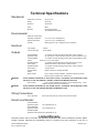
Technical Specifications...............................................................................................................
Limited Warranty.........................................................................................................................
Limitation of Liability....................................................................................................................
49
50
50
Appendix A..............................................................................................................................
Appendix B..............................................................................................................................
Appendix C. .............................................................................................................................
Appendix D. .............................................................................................................................
Appendix E.Compatible Signaling Devices...................................................................................
Reserved
Reserved
Reserved
Reserved
E-1
Remote SAFEPATH Manual
Rev. C December 1998
Sheet 5 of 50
List of Figures
Figure
Figure
Figure
Figure
Figure
Figure
Figure
Figure
Figure
Figure
Figure
Figure
Figure
Figure
Figure
Figure
1
2
3
4
5
6
7
8
9
10
11
12
13
14
15
16
Figure
17
Figure
18
Figure
19
Figure
Figure
Figure
Figure
Figure
Figure
Figure
Figure
Figure
20
21
22
23
24
25
26
27
28
Basic Capabilities of the Remote SAFEPATH Panel......................................................
Operator's Console..................................................................................................
Panel Mounting.......................................................................................................
Typical System Block Diagram..................................................................................
Field Wiring Input/Output Terminal Block Locations......................................................
Power Supply, Battery Charger, and Earth Ground Terminal Blocks................................
Line Level Input Wiring.............................................................................................
Typical AC Input Voltage Wiring................................................................................
Typical Battery Wiring..............................................................................................
Typical Earth Ground Wiring.....................................................................................
Output Terminal Block Detail.....................................................................................
Alarm Output Contact Connection Diagram.................................................................
System Trouble Output Contact Connection Diagram...................................................
Trouble Audible Output Wiring Diagram......................................................................
Visual Notification Appliance Output Wiring Diagram...................................................
Audio Notification Appliance Output Wiring Diagram
Using Audio Only Appliances in Central Amplified Applications.....................................
Audio Notification Appliance Output Wiring Diagram
Using Audio Only Appliances in Amplified Speaker Applications....................................
Notification Appliance Output Wiring Diagram
Using Combination Audio/Visual Appliances in Central Amplified Applications................
Notification Appliance Output Wiring Diagram
Using Combination Audio/Visual Appliances in Amplified Speaker Applications...............
Optional Remote Microphone (RMS-1) Wiring Diagram.................................................
Trouble Location Indicator Locations..........................................................................
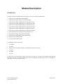
Module Layout of the Panel......................................................................................
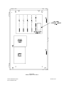
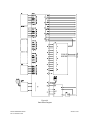
Panel Block Diagram................................................................................................
Supervised Audio System Mother Board.....................................................................
Supervised Audio System Common Control Module.....................................................
Self Amplified Speaker Control/Signal Circuit Module...................................................
Supervised Audio System Power Supply Module.........................................................
Supervised Audio System Battery Charger Module......................................................
Remote SAFEPATH Manual
Rev. C December 1998
Page
7
11
16
20
21
22
23
23
23
23
24
25
25
25
26
26
26
27
27
28
33
40
41
42
44
46
47
48
Sheet 6 of 50
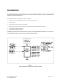
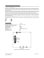
Introduction
Remote SAFEPATH provides remote amplification and remote live announcement capabilities to a centrally located SAFEPATH
panel. Remote SAFEPATH is capable of providing up to four zones of audible and visual signals. Figure 1 illustrates the basic
capabilities of the remote SAFEPATH panel.
This manual describes the remote SAFEPATH panel, which features:
•
A multitone generator with field selectable sounds for a manual evacuation signal.
•
Field upgradable.
•
Up to four audio and strobe circuits, zone selectable.
•
Supervision of input and output lines and many internal operations with trouble diagnosis and notification.
•
An optional Remote Microphone (RMS-1).
•
An optional Zone Splitter Module (SPL).
THE REMOTE SAFEPATH PANEL MUST BE PROPERLY INSTALLED, PROGRAMMED AND CONNECTED TO A CENTRALLY
LOCATED SAFEPATH PANEL TO FUNCTION IN A VOICE EVACUATION SYSTEM.
Figure 1.
Basic Capabilities of the Remote SAFEPATH Panel
Remote SAFEPATH Manual
Rev. C December 1998
Sheet 7 of 50
Operation
This chapter describes the operating characteristics of the remote SAFEPATH panel. Included is information about the following
features:
•
•
•
•
•
Operator's Console
Input and Output Options
Supervision
Operators Instructions
Back-up Battery Requirements
Operator's Console
An operator's console, which allows for manual override of the automatic message playing, is provided. The operator's console
includes a microphone, an "ACKNOWLEDGE" push-button, a "MANUAL/AUTOMATIC " switch, “ALL-CALL” switch, four “ZONE
DISARRANGEMENT” switches, and "NORMAL" and "TROUBLE" indicators. The operator's console is accessed by opening the
enclosure door. See Figure 2.
Input and Output Options
One line level input is provided for connecting to the central SAFEPATH panel.
Up to four audio outputs are available. Each output may be either a 15 Ohm line level output or a 25V, 70.7V or 100V amplifier
output. The 15 Ohm line level output can drive up to twenty 600 Ohm line level input appliances. The 25V, 70.7V or 100V amplifier
can drive up to 10, 40 or 80 Watts of speaker notification appliances.
Up to four visual appliance outputs are available. These outputs are rated for 24VDC and can each supply up to 2 amps of current.
Total current for all four outputs may not exceed 6 amps.
Up to four amplified speaker notification appliance power outputs are available. Each output is rated for 24VDC and can supply up
to 2 amps of current. Total current for all four outputs may not exceed 8 amps.
Supervision
A trouble condition indicates that the supervision functions have detected a malfunction in this panel. When a trouble condition is
detected, the panel may not be capable of playing emergency announcements.
If a trouble condition is detected by any of the supervision functions, the Form C status relay (normally energized) will change state,
the green system normal LED will turn off, and the amber trouble LED will turn on. The status relay contact closure must be properly
connected to and used by the control panel to indicate a system trouble. At the same time, an amber trouble location LED will
identify the location of the trouble condition. If a trouble condition is indicated, follow the procedures in the "Troubleshooting and
Servicing" section.
WARNING:
DO NOT LEAVE THIS SAFEPATH PANEL IN A TROUBLE CONDITION AS, IT MAY NOT PLAY WARNING
MESSAGES WHICH COULD RESULT IN PROPERTY DAMAGE AND SERIOUS INJURY OR DEATH TO YOU
AND/OR OTHERS. IF SAFEPATH INDICATES A TROUBLE CONDITION:
(1) PROVIDE UL REQUIRED
ALTERNATIVE SIGNALING AND (2) HAVE QUALIFIED SERVICE PERSONS IMMEDIATELY REPLACE UNIT(S)
THAT HAVE MALFUNCTIONED.
WARNING:
MESSAGES MADE BEFORE AND DURING A TROUBLE CONDITION MAY NOT BE HEARD, WHICH COULD
RESULT IN PROPERTY DAMAGE AND SERIOUS INJURY OR DEATH TO YOU AND/OR OTHERS. IF MESSAGES
MADE BEFORE AND DURING A TROUBLE CONDITION ARE STILL NECESSARY, THEY SHOULD BE REPEATED
WHEN THIS SAFEPATH PANEL IS RETURNED TO NORMAL.
Input Voltage Supervision
Input voltage is supervised, and if the input voltage drops below the operating minimum voltage, this panel will transfer to battery
back-up power and indicate a trouble condition.
Remote SAFEPATH Manual
Rev. C December 1998
Sheet 8 of 50
Microprocessor Supervision
Each microprocessor within this panel has a watchdog circuit that supervises the processor and resets it (if necessary) or maintains
a trouble condition if the microprocessor cannot be restarted. Each watchdog circuit constantly monitors the functioning of its
microprocessor and, if the microprocessor fails to function properly, will attempt to reset and restart the microprocessor.
Line Level Input Supervision
The line level input wiring is supervised by the central panel only. If either an open or short in the wiring should occur, the remote
panel will indicate an alarm condition.
Visual Notification Appliance Output Line Supervision
All visual notification appliance output lines are supervised. The lines are supervised for open circuits, short circuits, and ground
faults when the output is de-energized; and ground faults only when the output is energized. Output line supervision requires a
LISTED 10K end-of-line resistor to be installed on each output circuit and across the terminals of unused output circuits.
Audio Notification Appliance Output Line Supervision
All audio notification appliance output lines are supervised. The lines are supervised for open circuits, short circuits, and ground
faults when the output is de-energized. The lines are unsupervised when the output is energized. Output line supervision requires a
LISTED 10K end-of-line resistor to be installed on each output circuit and across the terminals of unused output circuits.
Amplified Speaker Notification Appliance Power Output Line Supervision
All amplified speaker notification appliance power output lines are supervised. The lines are supervised for open circuits, short
circuits, and ground faults when the output is de-energized, and ground faults only when the output is energized. Output line
supervision requires a LISTED 10K end-of-line resistor to be installed on each output circuit and across the terminals of unused
output circuits.
Battery Back-Up Line Supervision
The battery back-up lines are supervised for open circuits, short circuits and ground faults.
Back-Up Battery Supervision
The back-up battery is supervised for low voltage conditions.
Remote Microphone Supervision
The optional remote microphone is supervised for proper operation and for open circuits, short circuits and ground faults.
Remote SAFEPATH Manual
Rev. C December 1998
Sheet 9 of 50
Operator Instructions
The SAFEPATH panel provides an operator console for manually activating the panel. The operator console includes a
microphone, a green “NORMAL” indicator, a yellow “TROUBLE” indicator, an “ACKNOWLEDGE” push-button switch, a “RESET”
push-button, a “MANUAL/AUTOMATIC” switch, an “ALL-CALL” switch and four “ZONE SELECT” switches. The operator interface
allows the operator to manually override automatically playing pre-recorded messages with live announcements or an evacuation
tone, to silence internal and external trouble audibles, and to ascertain if the panel has detected a trouble condition. The operator
interface is shown in Figure 3.
The “TROUBLE” and “NORMAL” indicators are visible through a window on the panel door, when door is closed. All other operator
controls are only accessible by opening the panel door.
The “SELECT” LED’s indicate the zones selected for live announcements.
The ”ALARM” LED’s indicate the zones actively in alarm.
The two indicators identify to the operator when the SAFEPATH panel has detected a trouble condition. The yellow “TROUBLE”
indicator will be illuminated whenever there is a trouble detected by the SAFEPATH panel. If no troubles are detected, the green
“NORMAL” indicator will be illuminated.
The “ACKNOWLEDGE” push-button allows the operator to silence the trouble audibles, both internal and external. When a trouble
condition is detected, both the internal and external trouble audibles are sounded. When the “ACKNOWLEDGE” push-button is
depressed, the internal and external trouble audibles will be silenced. The trouble audibles will resound for subsequent trouble
conditions. The Form C trouble output contact will remain in the trouble condition and the “TROUBLE” indicator will remain
illuminated until all trouble conditions have been corrected.
The “RESET” push-button resets the strobe circuits after all initiating circuits are reset.
The “MANUAL/AUTOMATIC” switch has two positions, manual (down) and automatic (up). When the “MANUAL/AUTOMATIC”
toggle switch is in the automatic position, pre-recorded messages may be selected to play in individual circuits via dry contact inputs
and/or a serial communication interface. When the “MANUAL/AUTOMATIC” switch is in the manual position, pre-recorded
messages will not play, and the visual notification appliances are energized and the evacuation tone sounds in all circuits.
The “ALL-CALL” switch overrides any zone selection and allows audible signals to be heard regardless of the position of the four
zone select switches.
The four “ZONE SELECT” switches are numbered 1 through 4. They are used to silence any audible signal and turn off visual
signals in the respective zones, for live announcements only.
Operation Instructions
To make a live announcement:
1. Select specific zones or use “ALL-CALL” as necessary.
2. Remove microphone from its holder.
3. Hold down microphone’s push-to-talk button and talk into microphone.
To manually sound evacuation tone:
1. Move “MANUAL/AUTOMATIC” switch to the manual position.
The evacuation tone will sound in all circuits.
To silence trouble audibles:
1. Depress the “ACKNOWLEDGE” push-button.
To reset strobes:
1. All initiating circuits must be reset.
2. Momentarily depress the “RESET” push-button.
Remote SAFEPATH Manual
Rev. C December 1998
Sheet 10 of 50
Figure 2.
Operator’s Console
Remote SAFEPATH Manual
Rev. C December 1998
Sheet 11 of 50
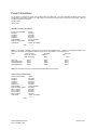
Power Calculations
It is necessary to calculate the current draw for battery back-up requirements. The current requirements depend on the system
configuration and the options installed. The total current is the sum of the currents of all the components in the system. There are
two different system current ratings:
Standby Current
Alarm Current
Standby Current Calculations:
System Controller Board
Amplifier 1
Amplifier 2
Amplifier 3
Amplifier 4
Optional RMS-1
Optional Trouble Audible
Optional SPL
150mA
See Note 1
See Note 1
See Note 1
See Note 1
40mA (If Installed)
See Note 2
40maA (If Installed)
________
Total:
Note 1: If no amplifier is installed in the slot then the current for that amplifier is zero. If there is an amplifier the standby current
depends on the model of the amplifier installed in the slot and the pre-selected 1 of 8 evacuation tones.
Model
Standby Current
As per UL full power
SIN wave testing
SALL-15S
SAA10S/SE Series
SAA40S/SE Series
SAA80S/SE Series
100mA
240mA
400mA
600mA
Temporal
CODE-3
TONE
Worst case
tone
HI/LO
100mA
125mA
300mA
300mA
100mA
150mA
300mA
400mA
Note 2: Use the rated current for the optional trouble audible attached to the system.
Alarm Current Calculations:
System Controller Board
Amplifier 1
Amplifier 2
Amplifier 3
Amplifier 4
Digital Voice
Optional RMS-1
Optional Trouble Audible
Zone 1 Strobes
Zone 2 Strobes
Zone 3 Strobes
Zone 4 Strobes
Optional SPL
150mA
See Note 4
See Note 4
See Note 4
See Note 4
See Note 5
75mA (If Installed)
See Note 6
See Note 7
See Note 7
See Note 7
See Note 7
190mA (If Installed)
________
Total:
Remote SAFEPATH Manual
Rev. C December 1998
Sheet 12 of 50
Note 3: If no amplifier is installed in the slot then the current for that amplifier is zero. If there is an amplifier the alarm current
depends on the model of the amplifier installed in the slot and the signal used for evacuation.
Model
SALL-15S Series
SAA-10S/SE Series
SAA-40S/SE Series
SAA-80S/SE Series
Alarm Current full power SIN wave as per UL testing
The sum of the currents of the self amplified speakers.
(total wattage of connected speakers) x 69 + 240mA
(total wattage of connected speakers) x 55 + 400mA
(total wattage of connected speakers) x 56 + 600mA
Alarm Current for:
Temporal
Worst case
CODE-3
tone
Typical Voice
TONE
HI/LO
250mA
350mA
750mA
600mA
750mA
1600mA
1000mA
1050mA
2500mA
SAA10S/SE Series
SAA40S/SE Series
SAA80S/SE Series
Note 4: Use the rated current for the optional trouble audible attached to the system.
Note 5: If no strobes are installed in the zone the current is zero. If strobes are installed, the current is the sum of the current ratings
of all the strobes attached to the zone.
Battery Capacity Calculations:
The battery capacity depends on two factors; the current being drawn from the battery and the amount of time that the current is
being drawn. The battery capacity is measured in amp hours. The total amp hours of batteries needed is (the standby current) x
(time in standby) + (the alarm current) x (time in alarm).
Sample Calculation:
The system is equipped with an RMS-1, a remote trouble audible that is rated for 100mA, and three amplifiers. The first amplifier is
an SAA-10S Series with 10 watts of speakers attached and 1 amp of strobes attached. The second amplifier is an SAA-80S Series
with 60 watts of speakers attached and 2 amps of strobes attached. The third amplifier is an SALL-15S Series with 10, 100mA self
amplified speakers attached and no strobes attached. The system is designed for 24 hours of standby and 15 minutes of alarm.
Standby Calculations:
System Controller Board
Amplifier 1
Amplifier 2
Amplifier 3
Amplifier 4
Optional RMS-1
Optional Trouble Audible
150mA
125mA
300mA
100mA
0mA
40mA
100mA
_______
Total: 815mA = .815 amps
Alarm Current Calculations:
System Controller Board
Amplifier 1
Amplifier 2
Amplifier 3
Amplifier 4
None
Optional RMS-1
Optional Trouble Audible
Zone 1 Strobes
Zone 2 Strobes
Zone 3 Strobes
Zone 4 Strobes
150mA
350mA
1050mA
1000mA
0mA
750mA
100mA
1000mA
2000mA
0mA
0mA
________
Total: 5725mA = 5.725 amps
Battery Capacity Calculations:
24 hours x .815 amps + 1/12 hour (5 minutes) x5.725 amps = 20.04 amp hours minimum capacity. Any de-rating factor must also
be included.
Remote SAFEPATH Manual
Rev. C December 1998
Sheet 13 of 50
Installation
The lives of people depend upon your safe installation of this panel. Please read, understand and carefully follow the specific
installation instructions set forth below to avoid damage to this panel and the equipment connected to it. Installation should be
conducted only by qualified persons in accordance with the procedures in this manual.
WARNING:
SHUT OFF ALL POWER BEFORE STARTING THE INSTALLATION. ELECTRICAL SHOCK CAN CAUSE
DEATH OR SERIOUS INJURY.
CAUTION:
This panel’s printed circuit boards are sensitive to static electricity and have delicate components mounted on
them. Before handling either a board or any component on a board, discharge any static electricity from your
body by touching a grounded object such as a metal screw which is connected to earth ground. Handle the
board by its edges, and be careful not to twist or flex it. This panel is to be installed in a static free area and the
user is to properly attach grounded wrist straps before touching any static sensitive areas. After handling this
panel’s printed circuit boards, the panel should be tested in accordance with the “System Checkout” guidelines
in the “Installation” section of this manual to verify that the printed circuit boards are undamaged and functioning
properly.
CAUTION:
The Authorities Having Jurisdiction (AHJ) should be consulted by the installer prior to installation.
1.
Prepare a drawing of the complete system wiring (Keep a copy of the system wiring drawing with this manual as a
permanent record of the system wiring). See the "Wiring Guidelines" and the "Field Wiring" sections to help develop
this drawing.
2.
Carefully unpack the panel and make sure each item described on the packing slip is present and undamaged.
3.
Mount the panel in the desired location as described in the "Mounting" section.
4.
Mount any additional wiring boxes or junction boxes needed to interconnect field wiring.
5.
Connect conduit fittings or bushings as needed using knockouts provided on the top and bottom of the panel.
6.
Install field wiring in conduit when necessary, following the National Electrical Code and local codes for the type of
system being installed. Make all necessary connections at any additional wiring or junction boxes.
CAUTION:
Provide proper strain relief for all wiring not in conduit.
7.
Connect the panel to earth ground, following the National Electrical Code and local codes for the type of system being
installed, as described in the “Grounding “ section.
8.
Check the integrity of all field wiring following the directions in the "Field Wiring Checkout'' section. Confirm that the
specified cable is installed and that there is continuity between required points (no open circuits), with no unwanted
connections (shorts) to other conductors, chassis, or earth ground.
9.
Connect the wiring to the appropriate terminals of the panel’s modules following the directions in the "Field Wiring"
section and the system wiring drawing created in Step 1.
10.
Install the appropriate amplifier modules into slots 1 thru 4 of the mother board.
11.
Configure the dip switches on the controller module and install into slot 5 of the mother board.
12.
Apply power and perform the operational tests described in the "System Checkout" section.
Remote SAFEPATH Manual
Rev. C December 1998
Sheet 14 of 50
Wiring Guidelines
WARNING:
ALL AUDIO WIRING SHOULD BE ROUTED AWAY FROM ANY HIGH VOLTAGE OR HIGH CURRENT
LINES (SUCH AS AC OR DC POWER LINE, AUDIO POWER LINES, AND MOTOR OR RELAY ACTUATION
LINES) AND SHOULD BE INSTALLED IN SEPARATE CONDUIT FROM HIGH VOLTAGE OR HIGH
CURRENT LINES. FAILURE TO DO SO MAY CAUSE ELECTRICAL SHOCK RESULTING IN PROPERTY
DAMAGE AND SERIOUS INJURY OR DEATH TO YOU AND/OR OTHERS.
The National Electrical Code defines two types of circuits for protective signaling systems: power limited circuits and non-power
limited circuits. All circuits in this panel are non-power limited.
CAUTION:
The National Electric Code limits the maximum number of conductors that can be installed in conduit and wiring
boxes depending on the size of the conduit, the volume of the boxes, and the gauge of the wire used. Make
sure that wiring used for installation complies with the latest NEC requirements.
See the “Field Wiring Connection” section for recommended wire sizes and wire type to use for all input and output circuits.
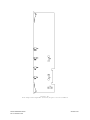
Mounting
This panel shall be mounted in a location within the environmental limits specified in the latest UL Standard for indoor control
panels. This panel shall not be located in a hazardous location. Refer to the "Technical Specifications'' section.
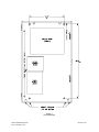
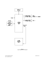
Refer to Figure 3 for panel mounting hole layout. Drill mounting holes for appropriate screws and anchors to ensure secure
mounting to the type of surface at the selected location. Keep out dust and dirt during installation, as they can interfere with the
operation and reduce the life of the equipment.
Remove the door and mount the panel at the selected location. Use care to avoid damage to the module PC boards during
installation. Do not apply excessive pressure to any PC board or its components, including field wiring terminals and connectors.
Grounding
This panel should be connected to earth ground in accordance with the National Electrical Code. Connecting this panel to earth
ground will reduce static discharge failures, improve transient protection, and reduce the chance of electrical shock. This panel
should be grounded as follows:
1.
Connect a wire between the ground lug (labeled “EARTH GROUND”) in Figure 6 and earth ground.
Remote SAFEPATH Manual
Rev. C December 1998
Sheet 15 of 50
Figure 3.
Panel Mounting
Remote SAFEPATH Manual
Rev. C December 1998
Sheet 16 of 50
Field Wiring
Before installation, the system specifier must determine the proper wire gauge for all field wiring. The field wiring is broken down
into two categories, inputs and outputs.
NOTE: All field wiring shall conform to applicable codes and standards including NFPA, UL, local, state, county, province, district
and federal codes and standards.
Field Wiring Connection
All wiring terminals are designed to accept #22 AWG to #12 AWG wiring (one wire per terminal). Connect the field wiring to the
terminals while referring to the following sections.
Install field wiring following the latest National Electrical Code and local codes for the type of system being installed. Make all
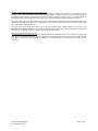
necessary connections. See Figure 4 for typical system block diagram.
Check the integrity of all field wiring following directions in the "Field Wiring Checkout" section. Confirm that the specified cable is
installed and there is continuity between required points (no "open circuits"), with no unwanted connections ("shorts") to other
conductors, chassis, or earth ground. Perform the field wiring checkout before continuing with any connections to the wiring
terminals.
WARNING:
TO REDUCE THE RISK OF ELECTRICAL SHOCK, NEVER CONNECT OR DISCONNECT FIELD WIRING
WHEN INPUT VOLTAGE OR BACK-UP BATTERIES ARE CONNECTED TO THIS SAFEPATH PANEL.
Input Wiring Descriptions
This panel has four types of inputs, the locations of which are shown in Figure 5. Detail of the power input and ground terminals is
shown in Figure 6.
Line Level Input Wiring
Determination of the wire gauge for the line level input wiring should consider all factors, including wire loop length and the
maximum allowable wire loop resistance of 10 ohms. The line level input wiring diagram’s are shown in Figure 7.
AC Input Voltage Wiring
Determination of wire gauge for the input voltage wiring should consider all factors, including wire loop length, AC power line
voltage, the panel’s maximum AC current consumption, and the panel’s AC input voltage range.
IT IS IMPORTANT THAT THE WIRING USED FOR INPUT VOLTAGE WIRING IS LARGE ENOUGH TO CARRY THE MAXIMUM
CURRENT REQUIRED BY THIS SAFEPATH PANEL WITHOUT EXCESSIVE VOLTAGE DROP. IF VOLTAGE DROPS FROM AC
POWER LINE LOADING AND WIRING RESISTANCE ARE NOT WITHIN THE SPECIFIED OPERATING VOLTAGE RANGE, THE
SAFEPATH PANEL WILL NOT FUNCTION PROPERLY.
A typical AC input voltage wiring diagram is shown if Figure 8. This panel shall have its own branch circuit on the main power panel.
The wiring from the main power panel shall terminate in the SAFEPATH panel on the power supply terminals as shown in Figure 8.
Wire jumpers shall then be run from the battery charger terminals to the power supply terminals as shown in Figure 8. The wire
jumpers between the battery charger terminals and the power supply terminals shall be the same gauge as the wire between the
main power panel and this panel.
Battery Wiring
Determination of the wire gauge for the battery wiring should consider all factors, including wire loop length and the maximum
allowable wire loop resistance. The maximum wire loop resistance is 0.05 ohms. A typical battery wiring diagram is shown in Figure
9.
Earth Ground Wiring
Determination of the wire gauge for the earth ground wiring should consider all factors, including wire length and the maximum
allowable wire resistance. A typical earth ground wiring diagram is shown in Figure 10.
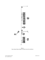
If the RSAPE is connected to the direct output of the amplifier at the audio outputs on the SAMB-A, then wire to the LLIM as shown
in Figure 7A. If the RSAPE is connected to the output of a splitter (SPL, SC-SPL), then wire to the LLIM as shown in Figure 7B.
Remote SAFEPATH Manual
Rev. C December 1998
Sheet 17 of 50
Output Wiring Descriptions
This panel has six types of outputs. The location of the outputs’ terminal blocks within this panel are shown in Figure 5. Detail of
the terminal blocks is shown in Figure 11.
Alarm Output Contact Wiring
One alarm output contact is provided. It is Form C and is rated for 0.5A at 24VDC, resistive load. A detail of the alarm output
contact terminal connections is shown in Figure 12. The contact in Figure 12 is shown in the non-alarm position. Determination of
wire gauge for the alarm output contact wiring should consider all factors, including wire loop length, maximum current capacity, and
maximum voltage drop allowable.
System Trouble Output Contact Wiring
One system trouble output contact is provided. It is Form C and is rated for 0.5 amps at 24VDC, resistive load. A detail of the
system trouble output contact terminal connections is shown in Figure 13. The contact in Figure 13 is shown in the trouble position.
Determination of wire gauge for the system trouble output contact wiring should consider all factors, including wire loop length,
maximum current capacity, and maximum voltage drop allowable.
Trouble Audible Output Wiring
One trouble audible output is provided. The output is rated for 24VDC, 0.1 amps maximum. The output is unsupervised. The
wiring diagram for the trouble audible output is shown in Figure 14. Determination of wire gauge for the trouble audible output wiring
should consider all factors, including wire loop length, maximum current capacity, and maximum voltage drop allowable.
Visual Notification Appliance Output Wiring
Up to four visual notification appliance outputs may be provided. Each output provided is rated for 24VDC, 2.0 amps maximum. All
four outputs combined may not exceed 6.0 amps maximum. Each output meets Class B, Style Y supervision requirements for
notification appliance circuits.
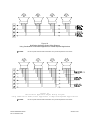
The wiring diagram for the visual notification appliance output using visual only appliances is shown in Figure 15. The wiring
diagram for a notification appliance output using combination audio/visual appliances in central amplified applications is shown in
Figure 18. The wiring diagram for a notification appliance output using combination audio/visual appliances in amplified speaker
applications is shown in Figure 19.
Each output circuit must have a LISTED 10K end-of-line resistor installed across the last visual notification appliance. All unused
outputs must have a LISTED 10K end-of-line resistor across the output terminals. The LISTED 10K end-of-line resistors must have
a 1/8W minimum power rating and a 5% maximum tolerance
The gauge of the wire necessary for the wiring may vary for each visual notification appliance output on the SAFEPATH panel.
Determination of wire gauge should consider all factors including wire loop length, the maximum current draw of each appliance, the
number of appliances, and the maximum voltage drop allowable.
Audio Notification Appliance Output Wiring
Up to four audio notification appliance outputs may be provided. Each output is either a central amplified output or an amplified
speaker output. Central amplified outputs are a 25V, 70.7V or 100V audio output, rated for 10, 40, or 80 watts maximum. Amplified
speaker outputs are 15 Ohm, -5dBm maximum. Each output meets Class B, Style Y supervision requirements for notification
appliance circuits.
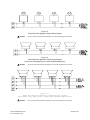
The wiring diagram for the audio notification appliance output using audio only appliances in central amplified applications is shown
in Figure 16. The wiring diagram for the audio notification appliance output using audio only appliances in amplified speaker
applications is shown in Figure 17. The wiring diagram for a notification appliance output using combination audio/visual appliances
in central amplified applications is shown in Figure 18. The wiring diagram for a notification appliance output using combination
audio/visual appliances in amplified speaker applications is shown in Figure 19.
Each output circuit must have a LISTED 10K end-of-line resistor installed across the last audio notification appliance. All unused
outputs must have a LISTED 10K end-of-line resistor across the output terminals. The LISTED 10K end-of-line resistors must have
a 1W minimum power rating and a 5% maximum tolerance
The gauge of the wire necessary for the wiring may vary for each audio notification appliance output on the SAFEPATH panel.
When speaker with transformer appliances are used (central amplified outputs), determination of wire gauge should consider all
factors including wire loop length, appliance power ratings, the number of appliances, and the maximum voltage drop allowable.
When amplified speaker appliances are used, determination of wire gauge should consider all factors including wire loop length,
output level, the output resistance, the input resistance of each appliance, the number of appliances, and the appliance input
sensitivity.
Remote SAFEPATH Manual
Rev. C December 1998
Sheet 18 of 50
Amplified Speaker Notification Appliance Power Output Wiring
Up to four amplified speaker notification appliance power outputs may be provided. Each output is rated for 24VDC, 2.0 amps
maximum. Each output meets Class B, Style Y supervision requirements for notification appliance circuits. The wiring diagram for
the amplified speaker notification appliance power output using audio only appliances is shown in Figure 17. The wiring diagram for
the amplified speaker notification appliance power output using combination audio/visual appliances is shown in Figure 19.
Each output circuit must have a LISTED 10K end-of-line resistor installed across the last appliance. All unused outputs must have a
LISTED 10K end-of-line resistor across the output terminals. The LISTED 10K end-of-line resistors must have a 1W minimum
power rating and a 5% maximum tolerance
The gauge of the wire necessary for the wiring may vary for each amplified speaker notification appliance power output on the
SAFEPATH panel. Determination of wire gauge should consider all factors including wire loop length, the maximum current draw of
each appliance, the number of appliances, and the maximum voltage drop allowable.
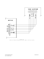
Remote Microphone Station (RMS-1) Wiring
Use twisted shielded wiring between the remote microphone station and the SAFEPATH panel. Connect shield to the panel ground
connection only. The maximum distance between the RMS-1 and the SAFEPATH panel is 1000 Ft. with a minimum wire size of 22
AWG, with a maximum capacitance of 50pF/Ft. or .05uF/Total run. The wiring diagram for the remote microphone station is shown
in Figure 20.
Remote SAFEPATH Manual
Rev. C December 1998
Sheet 19 of 50
Figure 4.
Typical System Block Diagram
Remote SAFEPATH Manual
Rev. C December 1998
Sheet 20 of 50
Figure 5.
Field Wiring
Input/Output Terminal Block Locations
Remote SAFEPATH Manual
Rev. C December 1998
Sheet 21 of 50
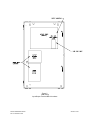
Figure 6.
Power Supply, Battery Charger And Earth Ground Terminal Blocks
Remote SAFEPATH Manual
Rev. C December 1998
Sheet 22 of 50
Figure 7A.
Line Level Input Wiring Diagram From Splitter
Output Diagram
Figure 7B.
Line Level Input Wiring Diagram From Amplifier
Output Diagram
Figure 8.
Typical AC Input Voltage Wiring
Figure 9.
Typical Battery Wiring
Remote SAFEPATH Manual
Rev. C December 1998
Figure 10.
Typical Earth Ground Wiring
Sheet 23 of 50
Figure 11.
Output Terminal Block Detail
Remote SAFEPATH Manual
Rev. C December 1998
Sheet 24 of 50
Figure 12.
Alarm Output Contact Connection Diagram
Figure 13.
System Trouble Output Contact Connection Diagram
(Contact shown in trouble condition)
Figure 14.
Trouble Audible Output Wiring Diagram
CAUTION:
Remote SAFEPATH Manual
Rev. C December 1998
Do not loop wire under terminals. Break wire run to provide supervision of connection.
Sheet 25 of 50
Figure 15.
Visual Notification Appliance Output Wiring Diagram
CAUTION:
Do not loop wire under terminals. Break wire run to provide supervision of connection.
Figure 16.
Audio Notification Appliance Output Wiring Diagram
Using Audio Only Appliances In Central Amplified Applications
CAUTION:
Do not loop wire under terminals. Break wire run to provide supervision of connection.
Figure 17.
Audio Notification Appliance Output Wiring Diagram
Using Audio Only Appliances In Amplified Speaker Applications
CAUTION:
Remote SAFEPATH Manual
Rev. C December 1998
Do not loop wire under terminals. Break wire run to provide supervision of connection.
Sheet 26 of 50
Figure 18.
Notification Appliance Output Wiring Diagram
Using Combination Audio/Visual Appliances In Central Amplified Applications
CAUTION:
Do not loop wire under terminals. Break wire run to provide supervision of connection.
Figure 19.
Notification Appliance Output Wiring Diagram
Using Combination Audio/Visual Appliances In Amplified Speaker Applications
CAUTION:
Remote SAFEPATH Manual
Rev. C December 1998
Do not loop wire under terminals. Break wire run to provide supervision of connection.
Sheet 27 of 50
Figure 20.
Optional Remote Microphone Station (RMS-1) Wiring Diagram
Remote SAFEPATH Manual
Rev. C December 1998
Sheet 28 of 50
Field Wiring Checkout
Refer to NFPA for guidelines on testing signaling system wiring.
CAUTION:
Do not connect input voltage to any equipment until the field wiring has been inspected and approved.
Verify that the field wiring is in full agreement with this manual and with the detailed wiring layout prepared for this installation.
Ensure that no unwanted voltages are present on circuit conductors and ground. Test all ungrounded connectors for electrical
isolation from ground. Test all wires that are not intentionally connected for electrical isolation from each other. Measure and record
the resistance of each circuit pair (this can be done by temporarily short circuiting one end of the circuit).
System Checkout
Refer to NFPA for guidelines on testing signaling systems.
When rated input voltage is applied to this panel, the unit initializes its program and broadcasts a tone signal through each output
channel for several seconds. The green system normal LED indicator should be on to indicate normal operation. If the amber
system trouble LED is on, a trouble condition is indicated. Refer to the "Troubleshooting and Servicing" section to diagnose and
correct the trouble condition.
The system checkout should include:
1.
Testing all inputs and outputs.
2.
Testing all connections to equipment that is interconnected with this panel.
3.
Testing all message files for proper audibility, intelligibility, content, and priority (message files are stored in the central panel).
If a malfunction is discovered during testing, the problem should be corrected immediately before continuing with testing.
WARNING:
ALL PROTECTIVE SIGNALING SYSTEMS REQUIRE PERIODIC TESTING. ALL PROTECTIVE SIGNALING
SYSTEM EQUIPMENT SHALL BE TESTED BY QUALIFIED PERSONNEL AT LEAST TWICE A YEAR FOR
PROPER OPERATION, OR MORE OFTEN IF REQUIRED BY CODES, REGULATIONS AND LAWS.
FAILURE TO MAINTAIN AND TEST PROTECTIVE SIGNALING SYSTEM EQUIPMENT CAN RESULT IN AN
INABILITY TO DETECT EQUIPMENT FAILURE THAT CAN RESULT IN PROPERTY DAMAGE AND
SERIOUS PERSONAL INJURY OR DEATH TO YOU AND/OR OTHERS DURING AN EMERGENCY
SITUATION.
Remote SAFEPATH Manual
Rev. C December 1998
Sheet 29 of 50
Installation and Care of Sealed Lead Acid Batteries
Sealed lead acid batteries are designed to operate in standby service for approximately five years. This is based upon a normal
service condition where there is an ambient of 20 degrees C (68 degrees F) and batteries are completely discharged once every
three months. LENGTH OF SERVICE LIFE WILL BE DIRECTLY EFFECTED BY THE NUMBER OF DISCHARGE CYCLES,
DEPTH OF DISCHARGE, AND AMBIENT TEMPERATURE.
Use Guidelines:
1.
Avoid installation and/or operation in close proximity to heat sources. While the operating temperature range is 0 to 49
degrees C (32-120 degrees F), battery life will be maximized at an ambient of 20 degrees C (68 degrees F).
2.
Batteries may generate ignitable gases. Because of this, batteries shall be installed in a well ventilated location, away from
spark producing equipment.
3.
Batteries shall not be installed in an atmosphere where organic solvents or adhesives may be present. The batteries shall not
be cleaned with oils, thinners, or similar substances. The case and cover of the batteries are ABS plastic resin which may
suffer damage from these chemicals.
4.
Batteries shall not be installed in a heavy vibration or shock location.
5.
Batteries shall have a 1/4” minimum separation between cells.
6.
Insulated gloves shall always be worn when handling batteries.
7.
Batteries shall not be crushed, incinerated, or dismantled. The electrolyte contains sulfuric acid which can cause serious
damage to eyes and skin. If contact does occur, flush with water and seek immediate medical attention.
8.
Batteries of different capacities, age, or manufacturer shall not be used together.
Battery Storage
Batteries which are to be stored for an extended period of time should be given a supplementary charge monthly. Batteries should
never be stored in a discharged condition.
The self-discharge rate of batteries is approximately 3% per month when the storage temperature is maintained at 20 degrees C (68
degrees F). The self-discharge rate will vary depending upon temperature. Cooler temperatures cause the self-discharge rate to
decrease. Warmer temperatures cause the self-discharge rate to increase.
Remote SAFEPATH Manual
Rev. C December 1998
Sheet 30 of 50
Troubleshooting
WARNING:
SOME ELECTRONIC COMPONENTS STORE A HIGH VOLTAGE CHARGE, EVEN THOUGH POWER IS
NOT CONNECTED, AND CAN CAUSE A DANGEROUS SHOCK IF TOUCHED. DO NOT TOUCH EXPOSED
CIRCUITRY ON THIS PANEL UNLESS THE CIRCUITRY HAS DISCHARGED FOR ONE HOUR AND A SAFE
DISCHARGE PROCEDURE IS USED.
WARNING:
PROVIDE UL REQUIRED ALTERNATIVE SIGNALING MEANS DURING TROUBLE CONDITIONS AND
SERVICING TO ASSURE ADEQUATE PROTECTION OF PEOPLE AND PROPERTY. HAVE QUALIFIED
SERVICE PERSONS IMMEDIATELY REPLACE ANY MODULES THAT HAVE MALFUNCTIONED.
CAUTION:
Troubleshooting and servicing should be conducted only by qualified persons in accordance with the
procedures in this manual. Do not attempt to make other adjustments, modifications, or repairs. Never use
water, steam, cleaning liquids or sprays on this SAFEPATH panel.
CAUTION:
User servicing of this is limited to the following:
-
Field wiring changes following the instructions in the "Installation" section of this manual.
-
The procedures set forth in this section.
CAUTION:
Do not paint or in any way cover window or LED's.
AFTER ANY TROUBLESHOOTING PROCEDURE IS COMPLETED, PERFORM A COMPLETE SYSTEM CHECKOUT.
This SAFEPATH panel monitors system integrity. Items monitored for integrity are:
1.
2.
3.
4.
5.
6.
7.
8.
9.
10.
11.
Strobe circuit field wiring.
Speaker circuit field wiring.
Amplified speaker audio circuit field wiring.
Amplified speaker power circuit field wiring.
AC input voltage.
Battery voltage level.
Battery circuit field wiring.
Amplifier functionality.
Internal wiring.
Internal fuses.
Remote microphone functionality and wiring.
System status is indicated to the operator via the NORMAL and TROUBLE indicators. If a trouble condition is detected, this
SAFEPATH panel will respond as follows:
1.
2.
3.
4.
5.
6.
Turn off the NORMAL indicator.
Turn on the TROUBLE indicator.
Transfer the Form C trouble contact to the trouble position.
Turn on the internal trouble sounder.
Turn on the external trouble audible.
Turn on a trouble location indicator, if appropriate.
If the ACKNOWLEDGE push-button is pressed, the internal trouble sounder and the external trouble audible will be silenced. All
other trouble indicators will still indicate a trouble condition. The internal trouble sounder and the external trouble audible will not
resound for subsequent trouble conditions, until all trouble conditions have cleared. If the main power fuse on the controller board is
blown, the internal trouble sounder and the external trouble audible will not sound. All other trouble indications occur normally.
When there are no trouble conditions detected, the NORMAL indicator will always be on and the TROUBLE indicator will always be
off. When a trouble condition is detected, the NORMAL indicator will always be off and the TROUBLE indicator will always be on.
Remote SAFEPATH Manual
Rev. C December 1998
Sheet 31 of 50
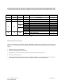
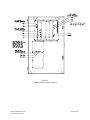
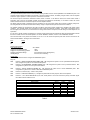
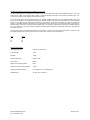
This panel has trouble location indicators which provide information as to what trouble condition has been detected and on which
part of the system the trouble is located. Figure 21 shows the location of all trouble location indicators within the panel. Table 1
cross references the trouble location indicators on the SABC, SALL-15S and SAA modules to the proper troubleshooting procedure.
Trouble Location Indicator/Troubleshooting Procedure Cross Reference
NORMAL
Indicator
On
Off
On
TROUBLE
Indicator
Off
Off
On
Module
---------SABC
SAA
Off
On
SALL-15S
Off
On
SADC
Indicator
---------PWR LOW
BAT LOW
BAT OPEN
AMP
SPK
STR
AMP
AUDIO
STROBE
AMP
D10
D11
D12
What it Means
Normal
Power Loss
Faulty Controller Module
Input Power Low
Battery Voltage Low
Battery Trouble
Amplifier Trouble
Audio Output Wiring Trouble
Visual Notification Output Wiring Trouble
Amplifier Trouble
Audio Output Wiring Trouble
Visual Notification Output Wiring Trouble
Amplifier Trouble
DV CH Play 10K Resistor Missing
Battery Charger Trouble
Remote Microphone Trouble
Troubleshooting
Procedure
---A
B
C
D
E
F
G
H
I
J
K
L
W
X
Y
Table 1.
Module Replacement Procedure
Return any modules that are malfunctioning, after all troubleshooting operations have been performed, for factory repair or
replacement. If it is necessary to return an individual module, replace the malfunctioning modules immediately in the following
manner:
1.
Disconnect AC input power from the panel.
2.
Disconnect battery back-up power from the panel.
3.
Identify all wiring connections to make sure they will be reconnected identically on the replacement.
4.
Disconnect all wiring connections.
5.
Remove the malfunctioning module(s) and install the replacement module(s). Perform all checkout procedures described in
the “Installation” section of this manual to make sure the replacement module(s) is (are) operating properly.
Remote SAFEPATH Manual
Rev. C December 1998
Sheet 32 of 50
Figure 21.
Trouble Location Indicator Locations
Remote SAFEPATH Manual
Rev. C December 1998
Sheet 33 of 50
BEFORE PERFORMING ANY OF THE FOLLOWING TROUBLESHOOTING PROCEDURES, THE PRELIMINARY
TROUBLESHOOTING INFORMATION AT THE BEGINNING OF THIS “TROUBLESHOOTING” SECTION MUST BE READ,
UNDERSTOOD, AND FOLLOWED.
Procedure A
If the green NORMAL indicator is off, the yellow TROUBLE indicator is off, and no module indicators are on, a power loss condition
has occurred. A power loss condition may be caused by:
1.
2.
3.
4.
5.
6.
7.
8.
9.
A blown fuse on the SAPS module.
A blown fuse on the SADC module
Loss of AC input power and battery back-up power.
Faulty internal wiring between the SAPS module and the SABC module.
Faulty internal wiring between SABC module and the backplane module.
Faulty SAPS module.
Faulty SABC module.
Faulty SADC module.
Faulty backplane module.
Perform the following:
1.
2.
3.
4.
5.
6.
7.
8.
9.
Verify that all fuses on the SAPS module are intact.
Verify that all fuses on the SADC module are intact.
Verify that AC input power and battery back-up power are present.
Verify that the wiring between the SAPS module and the SABC module is intact.
Verify that the wiring between the SABC module and the backplane module is intact.
Verify that the output voltage of the SAPS module is within its specification.
Verify that the output voltage of the SABC module is within its specification.
Swap SADC module with a known good module.
Replace the backplane module.
Procedure B
If the green NORMAL indicator is on and the yellow TROUBLE indicator is on, a faulty controller module condition has occurred. A
faulty controller module condition may be caused by:
1.
A faulty SADC module.
Perform the following:
1.
Replace the SADC module.
Procedure C
If the green NORMAL indicator is off, the yellow TROUBLE indicator is on, and the PWR LOW indicator on the SABC is on, an input
power low condition has occurred. An input power low condition may be caused by:
1.
2.
3.
A fuse on the SABC module is blown.
Low AC input power.
A faulty SABC module.
Perform the following:
1.
2.
3.
Verify that all fuses on the SABC module are intact.
Verify that the AC input power is within the correct operating range.
Replace the SABC.
Procedure D
If the green NORMAL indicator is off, the yellow TROUBLE indicator is on, and the BAT LOW indicator on the SABC module is on, a
battery voltage low condition has occurred. A battery voltage low condition may be caused by:
1.
2.
3.
Fully discharged batteries.
Faulty batteries.
A faulty SABC module.
Perform the following:
1.
2.
3.
Charge the batteries for 24 hours.
Replace the batteries.
Replace the SABC module.
Remote SAFEPATH Manual
Rev. C December 1998
Sheet 34 of 50
Procedure E
If the green NORMAL indicator is off, the yellow TROUBLE indicator is on, and the BAT OPEN indicator on the SABC module is on,
a battery trouble condition has occurred. A battery trouble condition may be caused by:
1.
2.
3.
A fuse on the SABC module is blown.
Faulty field wiring to batteries.
A faulty SABC module.
Perform the following:
1.
2.
3.
Verify that all fuses on the SABC module are intact.
Verify that the field wiring to the batteries is intact.
Replace the SABC module.
Procedure F
If the green NORMAL indicator is off, the yellow TROUBLE indicator is on, and the AMP indicator on the SAA module is on, an
amplifier trouble condition has occurred. An amplifier trouble condition may be caused by:
1.
2.
3.
4.
Faulty internal wiring between the backplane module and the digital voice module.
A faulty SAA module.
A faulty SADC module.
A faulty backplane module.
Perform the following:
1.
2.
3.
4.
Verify that the wiring between the backplane module and the digital voice module is intact.
Replace the SAA.
Replace the SADC module.
Replace the backplane module.
Procedure G
If the green NORMAL indicator is off, the yellow TROUBLE indicator is on, and the SPK indicator on the SAA module is on, an audio
output wiring trouble condition has occurred. An audio output wiring trouble condition may be caused by:
1.
2.
3.
4.
5.
Missing end-of-line resistor on the audio output.
The audio output field wiring is open or shorted.
A fuse on the SAA module is blown.
A faulty SAA module.
A faulty backplane module.
Perform the following:
1.
2.
3.
4.
5.
Verify that the end-of-line resistor is properly in place.
Verify that the audio output field wiring is intact.
Verify that all fuses on the SAA module are intact.
Replace the SAA module.
Replace the backplane module.
Procedure H
If the green NORMAL indicator is off, the yellow TROUBLE indicator is on, and the STR indicator on the SAA module is on, a visual
notification output wiring trouble condition has occurred. A visual notification output wiring trouble condition may be caused by:
1.
2.
3.
4.
5.
Missing end-of-line resistor on the visual notification output.
The visual notification output field wiring is open or shorted.
A fuse on the SAA module is blown.
A faulty SAA module.
A faulty backplane module.
Perform the following:
1.
2.
3.
4.
5.
Verify that the end-of-line resistor is properly in place.
Verify that the visual notification output field wiring is intact.
Verify that all fuses on the SAA module are intact.
Replace the SAA module.
Replace the backplane module.
Remote SAFEPATH Manual
Rev. C December 1998
Sheet 35 of 50
Procedure I
If the green NORMAL indicator is off, the yellow TROUBLE indicator is on, and the AMP indicator on the SALL-15S module is on, an
amplifier trouble condition has occurred. An amplifier trouble condition may be caused by:
1.
2.
3.
4.
Faulty internal wiring between the backplane module and the digital voice module.
A faulty SALL-15S module.
A faulty SADC module.
A faulty backplane module.
Perform the following:
1. Verify that the wiring between the backplane module and the digital voice module is intact.
2. Replace the SALL-15S module.
3. Replace the SADC module.
4. Replace the backplane module.
Procedure J
If the green NORMAL indicator is off, the yellow TROUBLE indicator is on, and the AUDIO indicator on the SALL-15S module is on,
an audio output wiring trouble condition has occurred. An audio output wiring trouble condition may be caused by:
1.
2.
3.
4.
5.
Missing end-of-line resistor on the audio output.
The audio output field wiring is open or shorted.
A fuse on the SALL-15S module is blown.
A faulty SALL-15S module.
A faulty backplane module.
Perform the following:
1. Verify that the end-of-line resistor is properly in place.
2. Verify that the audio output field wiring is intact.
3. Verify that all fuses on the SALL-15S module are intact.
4. Replace the SALL-15S module.
5. Replace the backplane.
Procedure K
If the green NORMAL indicator is off, the yellow TROUBLE indicator is on, and the STROBE indicator on the SALL-15S module is
on, a visual notification output wiring trouble condition has occurred. A visual notification output wiring trouble condition may be
caused by:
1.
2.
3.
4.
5.
Missing end-of-line resistor on the visual notification output.
The visual notification output field wiring is open or shorted.
A fuse on the SALL-15S module is blown.
A faulty SALL-15S module.
A faulty backplane module.
Perform the following:
1. Verify that the end-of-line resistor is properly in place.
2. Verify that the visual notification output field wiring is intact.
3. Verify that all fuses on the SALL-15S module are intact.
4. Replace the SALL-15S module.
5. Replace the backplane module.
Procedure L
If the green NORMAL indicator is off, the yellow TROUBLE indicator is on, and the PWR indicator on the SALL-15S module is on,
an amplified speaker power output wiring trouble condition has occurred. An amplified speaker power output wiring trouble condition
may be caused by:
1.
2.
3.
4.
5.
Missing end-of-line resistor on the amplified speaker power output.
The amplified speaker power output field wiring is open or shorted.
A fuse on the SALL-15S module is blown.
A faulty SALL-15S module.
A faulty backplane module.
Perform the following:
1. Verify that the end-of-line resistor is properly in place.
2. Verify that the amplified speaker power output field wiring is intact.
3. Verify that all fuses on the SALL-15S module are intact.
4. Replace the SALL-15S module.
5. Replace the backplane module.
Procedures M thru V
Reserved for future use
Remote SAFEPATH Manual
Rev. C December 1998
Sheet 36 of 50
Procedure W
If the green NORMAL indicator is off, the yellow TROUBLE indicator is on, and SADC D10 is on, the wiring between the DV channel
play contacts and the backplane is defective or the 10K ohm resistor attached to the DV channel play contacts is defective or
missing.
Perform the following:
1.
Verify field wiring between the backplane and the DV is intact.
2.
Verify the 10K ohm resistor across the DV channel play contacts is intact. Refer to procedures C, D and E.
Procedure X
If the green NORMAL indicator is off, the yellow TROUBLE indicator is on, and SADC D11 is on, the Battery Charger is defective or
mis-wired
Perform the following:
1.
Check the wiring between the backplane and the Battery Charger board.
2.
Refer to procedures C, D and E.
Procedure Y
If the green NORMAL indicator is off, the yellow TROUBLE indicator is on, and SADC D12 is on, the Remote Microphone (RMS-1)
has 1 or more troubles.
Perform the following:
1.
Verify that field wiring between the backplane and Remote Microphone Station is intact.
2.
Verify that all fuses on the SADC are intact.
Remote SAFEPATH Manual
Rev. C December 1998
Sheet 37 of 50
Periodic Testing
IMPORTANT: Periodic testing, including this panel, all notification equipment and all messages, including their audibility and
intelligibility, content and language, sequence, output channel, and priority assignment, must be conducted frequently, at least twice
each year, or more often as required by local, state and federal codes, regulations and laws, by qualified personnel to ensure proper
operation of all equipment. If the notification equipment is not working properly, immediately contact the installer and have all/any
problems corrected immediately. Malfunctioning units should be replaced immediately. Do not attempt to repair malfunctioning
units. Malfunctioning units should be returned for factory repair or replacement. In the event you cannot contact the installer,
contact the manufacturer.
WARNING:
PROVIDE ALTERNATIVE SIGNALING MEANS DURING PERIODIC TESTING TO ASSURE ADEQUATE
PROTECTION OF PEOPLE AND PROPERTY. FAILURE TO PROVIDE ALTERNATIVE SIGNALING MAY
CAUSE PEOPLE TO NOT BE WARNED OF AN EMERGENCY CONDITION WHICH COULD RESULT IN
PROPERTY DAMAGE AND SERIOUS INJURY OR DEATH TO YOU AND/OR OTHERS.
In addition to testing required by relevant fire codes, regulations and laws, several hardware functions should also be tested. The
hardware functions that should be tested are as follows:
1.
The polarity detection circuitry for line level input.
2.
The alarm contact.
3.
The "open circuit" and “short circuit” detection circuitry for any one or all of the notification appliance output circuits.
4.
The amplifier supervision circuitry for any one or all of the amplifiers.
5.
The status contact.
These hardware functions may be tested as follows:
1.
Make a live announcement from the central SAFEPATH and verify that the proper message plays.
2.
Monitor the alarm contact to verify proper operation while making a live announcement from the remote panel.
3.
While in the standby condition, open and short circuit each notification appliance circuit and verify that the proper trouble
condition is indicated.
4.
Listen to a message playing out each zone and check for audibility of message.
5.
Monitor the status contact while causing the panel to alternate between trouble and normal states to verify proper operation.
If the Remote SAFEPATH panel fails to perform any of the above tests correctly, immediately replace the malfunctioning module(s)
following the Module Replacement Procedure given in the “Troubleshooting” section.
Remote SAFEPATH Manual
Rev. C December 1998
Sheet 38 of 50
Module Description
Introduction
The thirteen modules in the SAFEPATH product line which can be used in the Remote SAFEPATH are:
1. Supervised Audio System Mother Board (SAMB-A)
2. Supervised Audio System Common Control Module (SADC)
3. Supervised Audio System Amplifier/Signal Circuit Module (SAA-10S)
4. Supervised Audio System Amplifier/Signal Circuit Module (SAA-10SE)
5. Supervised Audio System Amplifier/Signal Circuit Module (SAA-40S)
6. Supervised Audio System Amplifier/Signal Circuit Module (SAA-40SE)
7. Supervised Audio System Amplifier/Signal Circuit Module (SAA-80S)
8. Supervised Audio System Amplifier/Signal Circuit Module (SAA-80SE)
9. Self Amplified Speaker Control/Signal Circuit Module (SALL-15S)
10. Supervised Audio System Power Supply Module (SAPS)
11. Supervised Audio System Battery Charger Module (SABC)
12. Remote Microphone Station (RMS-1)
13. Line Level Interface Module (LLIM)
Each SAFEPATH panel is configured with:
•
One SAMB-A
•
One SADC
•
Between one and four amplifier modules (any combination of SAA’s and SALL-15S’s)
•
One SAPS
•
One SABC
•
One LLIM
The interior view of the panel with the modules in place is shown in Figure 22. The location of the amplifier modules (SAA and
SALL-15S) is not shown. The amplifier modules may be used in any combination by installing into slots 1 thru 4 in the SAMB-A. A
block diagram of the panel is shown in Figure 23.
Remote SAFEPATH Manual
Rev. C December 1998
Sheet 39 of 50
Figure 22.
Module Layout of the Panel
Remote SAFEPATH Manual
Rev. C December 1998
Sheet 40 of 50
Figure 23.
Panel Block Diagram
Remote SAFEPATH Manual
Rev. C December 1998
Sheet 41 of 50
Supervised Audio System Mother Board (SAMB-A)
The supervised audio system mother board (SAMB-A) provides all signal handling capabilities between the SADC and the amplifier
modules, terminal blocks for output wiring, and connectors for handling signals between the SADC and the digital voice module and
the SABC.
The SAMB-A is illustrated in Figure 24.
Up to four amplifier modules may be connected to the SAMB-A. The amplifier modules may be installed in any order in slots 1
through 4. Installing an amplifier module in slot 1 thru 4 will result in the module’s output appearing in the correspondingly
numbered terminal block (labeled “Zone 1” thru “Zone 4”). For example, when an amplifier module is installed in slot 1, the amplifier
module’s output appears at the terminal block labeled “Zone 1”.
Only one SADC may be connected to the SAMB-A. The SADC may only be installed in slot 5.
Up to four channels from a digital voice module may be connected to the SAMB-A. The digital voice module channels may be
connected in any order to connectors J8 through J11. The digital voice module channel connected to J8 will play through Zone 1; if
connected to J9, it will play through Zone 2; if connected to J10, it will play through Zone 3; if connected to J11, it will play through
Zone 4.
Connector J14 is the microphone input. J7 is the line out which should be connected to the DX-200’s auxiliary input (J7 should be
left unconnected in DX-100 configured systems). J12 is used to bring power to the digital voice module and monitor the digital voice
module’s status contact. J13 is used to monitor the SABC’s status.
Figure 24.
Supervised Audio System Mother Board
Remote SAFEPATH Manual
Rev. C December 1998
Sheet 42 of 50
Supervised Audio System Common Control Module (SADC)
The supervised audio system common control module (SADC) provides all of the control capabilities to the SAFEPATH panel. The
controller module monitors the digital voice module or line level interface module, the battery charger module, and the amplifier
modules for proper operation. The microphone is monitored for connection.
The line level input is monitored to determine its status, active or inactive. If the status is inactive, the control module routes a
supervision tone to each of the amplifier modules and monitors the amplifier for functionality. If the status is active, the control
module routes the audio from the line level input to the four amplifier modules.
The battery charger module is monitored for three conditions: low AC input power, battery wiring trouble, and battery voltage low.
The wiring between the controller module and the battery charger is supervised for open and short circuit conditions.
The amplifier modules are supervised for two failure conditions: field wiring trouble conditions and amplifier audio output trouble
conditions. The controller module only supervises the audio output during standby conditions. When either a message is playing
from the digital voice module or a live announcement is being made from the microphone, the field wiring and audio output are not
supervised.
If at any time a trouble condition is detected, the controller module will energize the internal and external trouble audibles, transfer
the Form C trouble contact to the trouble position, turn off the “NORMAL” indicator, and turn on the “TROUBLE” indicator.
There are two fuses on the printed circuit board, F1 and F2. F1 is the remote microphone power fuse and F2 is the fuse for the
external trouble audible. See Figure 25 for fuse location.
Fuse
F1
F2
Rating
0.5A
0.5A
Nominal Specifications:
Input Voltage Range
Supply Current (Idle) @ 24VDC
Supply Current (Full Load) @ 24VDC
Operating Temperature Range
Humidity Range
20 to 28VDC
75mA
150mA
0 to 49 Degrees C (32-120 Degrees F)
0 to 85%, Non-condensing
Configuration
There are 8 dip switches used to configure the SAFEPATH system:
They are:
SW8
Position 1, REMOTE MICROPHONE ENABLE (RM). ON configures the system to use an optional Remote Microphone.
OFF configures the system to use no Remote Microphone.
SW8
Position 2, SYNCHRONIZED STROBES ENABLE (SS). ON configures the system to use synchronized strobes. OFF
configures the system to use non-synchronized strobes.
SW8
Position 3, Remote SAFEPATH ENABLE (SL). ON configures the system to be a remote SAFEPATH panel. OFF
configures the system to be a central or stand-alone SAFEPATH panel.
SW8
Position 4, Future Use (FU). Leave in OFF position.
SW9
Position 1, LAMP TEST ENABLE (LT). ON lights the panel LED’S for test purposes, leave in OFF position.
SW9
Position 2, 3, & 4, MULTITONE SELECT (TS1, TS2, & TS3) selects 1 of 8 tones used for the primary evacuation signal.
Use Table 2 below to select the tone.
SWITCH SETTINGS FOR AVAILABLE TONE SOUNDS
TONE SOUND
SW9-2
Horn (Continuous)
ON
Bell (1560Hz Modulated)
ON
March Time Horn (.25 Sec ON .25 Sec. OFF)
OFF
Code-3 Horn (ANSI S3.41 Temporal Pattern)
ON
Code-3 Tone 500Hz (ANSI S3.41 Temporal Pattern)
OFF
Slow Whoop (500-1200Hz Sweep)
OFF
Siren (600-1200 Hz Sweep)
ON
HI/LO (1000/800Hz)
OFF
SW9-3
ON
OFF
OFF
ON
ON
ON
OFF
OFF
SW9-4
ON
ON
ON
OFF
ON
OFF
OFF
OFF
Table 2.
Remote SAFEPATH Manual
Rev. C December 1998
Sheet 43 of 50
Figure 25.
Supervised Audio System Common Control Module
Remote SAFEPATH Manual
Rev. C December 1998
Sheet 44 of 50
Self Amplified Speaker Control/Signal Circuit Module, (SALL-15S)
The self amplified speaker control/signal circuit module, (SALL-15S) provides audio output for the SAFEPATH system. The circuit
module has a -5 dBm, 15 ohm audio output, a 24VDC, 2A speaker amplifier power output, and a 24VDC, 2A strobe output. The
circuit module contains a linear amplifier and supervision circuitry.
The circuit module supervises the strobe field wiring, the speaker amplifier audio field wiring, the speaker amplifier power field
wiring, and the amplifier. The strobe field wiring and the speaker amplifier power wiring are supervised with a reverse polarity
technique, which applies a DC voltage with one polarity to supervise the wiring and then reverses the polarity to energize the
strobes. The speaker amplifier audio field wiring is supervised with a DC current which is removed when audio is being played.
Both field wiring circuits are only supervised in the standby state. The amplifier is supervised by monitoring the amplifier output for
audio. The state of each of the four supervision features is indicated via four indicators on the printed circuit board. See Figure 26
for indicator locations.
There are three fuses on the printed circuit board, F1 and F2, and F3. Fuse F1 is the fuse for the strobe power. F2 is the fuse for
the speaker amplifier power. F3 is the main fuse for the entire board. See Figure 26 for fuse locations.
Fuse
Rating
F1
F2
F3
3A
3A
6A
Nominal Specifications:
Rated Output @ 1kHz
500m Vrms, 15 ohm load
Input Sensitivity
1Vrms
S/N Ratio
-75dB
Frequency Response
275Hz to 4kHz
Input Voltage
24VDC
Supply Current (Idle) @ 24VDC
50mA
Supply Current (Full Load) @ 24VDC
135mA
Operating Temperature Range
0 to 49 Degrees C (32-120 Degrees F)
Humidity Range
0 to 85%, Non-condensing
Remote SAFEPATH Manual
Rev. C December 1998
Sheet 45 of 50
Figure 26.
Self Amplified Speaker Control/Signal Circuit Module
Remote SAFEPATH Manual
Rev. C December 1998
Sheet 46 of 50
Supervised Audio System Power Supply Module (SAPS)
The supervised audio system power supply module (SAPS) converts 120VAC line voltage to 24VDC output voltage. The power
supply module is capable of converting up to 500W and its output is over current protected.
There is one fuse on the printed circuit board, F1. Fuse F1 is the main fuse for the entire board. See Figure 27 for fuse location.
Fuse
Rating
F1
10A
Nominal Specifications:
Rated Output
Input Voltage
Supply Current (Full Load) @ 120VAC
Efficiency @ 120VAC, Full Load
Operating Temperature Range
Humidity Range
500W
120VAC
6.4A
88%
0 to 49 Degrees C (32-120 Degrees F)
0 to 85%, Non-condensing
Figure 27.
Supervised Audio System Power Supply Module
Remote SAFEPATH Manual
Rev. C December 1998
Sheet 47 of 50
Supervised Audio System Battery Charger Module (SABC)
The supervised audio system battery charger module (SABC) provides battery charging and supervision as well as AC power
supervision for the SAFEPATH system.
The SABC monitors three parameters: AC input power, battery wiring and battery voltage. When a low AC input power condition is
detected, the PWR LOW indicator is illuminated. When a battery wiring open condition is detected, the BAT OPEN indicator is
illuminated. When a low battery voltage condition is detected, the BAT LOW indicator is illuminated. See Figure 28 for the indicator
locations on the SABC.
The battery charger operates on the dual voltage charging principal, thereby achieving the highest possible level of charge in the
shortest amount of time while maintaining battery reliability. The charging circuit is enabled when the AC voltage is within the
specified range, the SAFEPATH system is not in alarm, and the battery voltage is above the charge enable threshold level.
When charging begins, the current will be limited to the fast charge rate. As the batteries charge, the terminal voltage increases.
The terminal voltage is eventually limited to the overcharge voltage level and the charging current begins to drop. When the
charging current drops below the overcharge termination current the float state is entered. At this time the batteries are
approximately 90% charged.
There are three fuses on the printed circuit board, F1, F2, and F3. F1 is the fuse for the battery wiring. Fuse F2 is the DC supply
fuse which directly powers the charging circuitry. F3 is the fuse for the AC input voltage supervision circuitry. See Figure 28 for fuse
locations.
Fuse
Rating
F1
F2
F3
30A
10A
0.5A
Nominal Specifications:
AC Supply Voltage
DC Supply Voltage Range
DC Supply Current @ 24VDC, Bulk Charge Rate
Fast Charge Rate Current @ Vbat = 26VDC
Overcharge Voltage
Overcharge Termination Current
Float State Voltage
Charge Enable Voltage
Battery Type
Nominal Battery Voltage
Maximum Battery Capacity
120VAC
20.4VDC to 26.4VDC
3.7A
2.6A
28.9VDC
469mA
27.3VDC
20VDC
Lead Acid Starved Electrolyte
24VDC
72AH
Figure 28.
Supervised Audio System Battery Charger Module
Remote SAFEPATH Manual
Rev. C December 1998
Sheet 48 of 50
Technical Specifications
Mechanical
Dimensions (H x W x D)
36" by 24" x 6"
Weight
90 pounds
Enclosure
0.050" Steel
Finish
Black
Mounting
Indoor Surface Mount
Top and Bottom Wiring Entry
Environmental
(Meets UL requirements)
Operating Temperature
0° to +49° C (32 to 120 Degrees F)
Storage Temperature
-20° to 70° C (-4 to 158 Degrees F)
Humidity
85±5% @ 30±2° C (86 ± 4 Degrees F) Non-condensing
Electrical
Input Voltage:
120VAC
Input Current (max):
8.0 at 120VAC
Outputs
Visual Notification
Appliance Output
WARNING:
Central Amplified
Output
1 to 4 output channels optionally provided; each programmable for Audio
either 25V, 70.7V or 100V output.
Amplified Speaker
Audio Output
1 to 4 output channels optionally provided; each through 15 Ohm
isolation transformer. Output level is -5 dBm maximum
Amplified Speaker
Power Output
1 to 4 output channels optionally provided; each output is rated for
2.0 Amps at 24V.
Trouble Audible
Output
Output is rated for 0.100 Amps at 24VDC
Status Contact
Form C contact normally energized. Contacts transfer during trouble.
Rated 0.5 Amps at 24VDC max, resistive load.
DO NOT EXCEED THE RATINGS OF THE STATUS CONTACT. EXCEEDING THE RATINGS MAY CAUSE
THE RELAY TO FAIL AND PREVENT A TROUBLE CONDITION FROM BEING INDICATED.
Alarm Contact
WARNING:
1 to 4 output channels optionally provided; each output is rated for
2.0 Amps at 24V. Total of all output channels may not exceed 6.0 Amps.
Form C contact normally de-energized. Contact transfers during
Rated 0.5 Amps at 24VDC max, resistive load.
alarm.
DO NOT EXCEED THE RATINGS OF THE ALARM CONTACT. EXCEEDING THE RATINGS MAY CAUSE
THE RELAY TO FAIL AND PREVENT MESSAGES FROM BEING PLAYED.
Wiring Connections
Screw Terminals
Each terminal accepts one conductor from #22 to #12 AWG.
End-of-Line Resistor
Visual Notification
Appliance Outputs
10K, 1/8W Minimum, 5%
Audio Notification
Appliance Outputs
10K, 1W Minimum, 5%
Amplified Speaker
Appliance Power Outputs 10K, 1/8W Minimum, 5%
Limited Warranty
Wheelock products must be used within their published specifications and must be PROPERLY specified, applied,
installed, operated, maintained and operationally tested in accordance with these instructions at the time of
Remote SAFEPATH Manual
Rev. C December 1998
Sheet 49 of 50
installation and at least twice a year or more often and in accordance with local, state and federal codes, regulations
and laws. Specification, application, installation, operation, maintenance and testing must be performed by qualified
personnel for proper operation in accordance with all of the latest National Fire Protection Association (NFPA),
Underwriters' Laboratories (UL), Underwriters’ Laboratories of Canada (ULC), National Electrical Code (NEC),
Occupational Safety and Health Administration (OSHA), local, state, county, province, district, federal and other
applicable building and fire standards, guidelines, regulations, laws and codes including, but not limited to, all
appendices and amendments and the requirements of the local authority having jurisdiction (AHJ). Wheelock
products when properly specified, applied, installed, operated, maintained and operationally tested as provided above
are warranted against mechanical and electrical defects for a period of three years from date of manufacture (as
determined by date code). Correction of defects by repair or replacement shall be at Wheelock's sole discretion and
shall constitute fulfillment of all obligations under this warranty. THE FOREGOING LIMITED WARRANTY SHALL
IMMEDIATELY TERMINATE IN THE EVENT ANY PART NOT FURNISHED BY WHEELOCK IS INSTALLED IN THE
PRODUCT. THE FOREGOING LIMITED WARRANTY SPECIFICALLY EXCLUDES ANY SOFTWARE REQUIRED
FOR THE OPERATION OF OR INCLUDED IN A PRODUCT. WHEELOCK MAKES NO REPRESENTATION OR
WARRANTY OF ANY OTHER KIND, EXPRESS, IMPLIED OR STATUTORY WHETHER AS TO
MERCHANTABILITY, FITNESS FOR A PARTICULAR PURPOSE OR ANY OTHER MATTER.
USERS ARE SOLELY RESPONSIBLE FOR DETERMINING WHETHER A PRODUCT IS SUITABLE FOR THE
USER'S PURPOSES, OR WHETHER IT WILL ACHIEVE THE USER'S INTENDED RESULTS. THERE IS NO
WARRANTY AGAINST DAMAGE RESULTING FROM MISAPPLICATION, IMPROPER SPECIFICATION, ABUSE,
ACCIDENT OR OTHER OPERATING CONDITIONS BEYOND WHEELOCK'S CONTROL.
SOME WHEELOCK PRODUCTS CONTAIN SOFTWARE. WITH RESPECT TO THOSE PRODUCTS, WHEELOCK
DOES NOT WARRANTY THAT THE OPERATION OF THE SOFTWARE WILL BE UNINTERRUPTED OR ERRORFREE OR THAT THE SOFTWARE WILL MEET ANY OTHER STANDARD OF PERFORMANCE, OR THAT THE
FUNCTIONS OR PERFORMANCE OF THE SOFTWARE WILL MEET THE USER'S REQUIREMENTS.
WHEELOCK SHALL NOT BE LIABLE FOR ANY DELAYS, BREAKDOWNS, INTERRUPTIONS, LOSS,
DESTRUCTION, ALTERATION, OR OTHER PROBLEMS IN THE USE OF A PRODUCT ARISING OUT OF OR
CAUSED BY THE SOFTWARE.
THE LIABILITY OF WHEELOCK ARISING OUT OF THE SUPPLYING OF A PRODUCT, OR ITS USE, WHETHER
ON WARRANTIES, NEGLIGENCE, OR OTHERWISE, SHALL NOT IN ANY CASE EXCEED THE COST OF
CORRECTING DEFECTS AS STATED IN THE LIMITED WARRANTY AND UPON EXPIRATION OF THE
WARRANTY PERIOD ALL SUCH LIABILITY SHALL TERMINATE. WHEELOCK IS NOT LIABLE FOR LABOR
COSTS INCURRED IN REMOVAL, REINSTALLATION OR REPAIR OF THE PRODUCT BY ANYONE OTHER
THAN WHEELOCK OR FOR DAMAGE OF ANY TYPE WHATSOEVER, INCLUDING BUT NOT LIMITED TO, LOSS
OF PROFIT OR INCIDENTAL OR CONSEQUENTIAL DAMAGES. THE FOREGOING SHALL CONSTITUTE THE
SOLE REMEDY OF THE PURCHASER AND THE EXCLUSIVE LIABILITY OF WHEELOCK.
IN NO CASE WILL WHEELOCK'S LIABILITY EXCEED THE PURCHASE PRICE PAID FOR A PRODUCT.
Limitation of Liability
WHEELOCK'S LIABILITY ON ANY CLAIM OF ANY KIND, INCLUDING NEGLIGENCE AND BREACH OF
WARRANTY, FOR ANY LOSS OR DAMAGE RESULTING FROM, ARISING OUT OF, OR CONNECTED WITH
THIS CONTRACT, OR FROM THE MANUFACTURE, SALE, DELIVERY, RESALE, REPAIR OR USE OF ANY
PRODUCT COVERED BY THIS ORDER SHALL BE LIMITED TO THE PRICE APPLICABLE TO THE PRODUCT
OR PART THEREOF WHICH GIVES RISE TO THE CLAIM. WHEELOCK'S LIABILITY ON ANY CLAIM OF ANY
KIND SHALL CEASE IMMEDIATELY UPON THE INSTALLATION IN THE PRODUCT OF ANY PART NOT
FURNISHED BY WHEELOCK. IN NO EVENT SHALL WHEELOCK BE LIABLE FOR ANY CLAIM OF ANY KIND
UNLESS IT IS PROVEN THAT OUR PRODUCT WAS A DIRECT CAUSE OF SUCH CLAIM. FURTHER, IN NO
EVENT, INCLUDING IN THE CASE OF A CLAIM OF NEGLIGENCE, SHALL WHEELOCK BE LIABLE FOR
INCIDENTAL OR CONSEQUENTIAL DAMAGES. SOME STATES DO NOT ALLOW THE EXCLUSION OR
LIMITATION OF INCIDENTAL OR CONSEQUENTIAL DAMAGES, SO THE PRECEDING LIMITATION MAY NOT
APPLY TO ALL PURCHASERS.
Remote SAFEPATH Manual
Rev. C December 1998
Sheet 50 of 50