1
© 2013, Moog Videolarm, Inc. All Rights Reserved
FCH360
Fusion Camera Housing with Panomorph Lens Options
www.moogvideolarm.com
Installation and Operation Instructions for the following models:
FCH360CW Environmental housing with feed-thru wall/pole mount with 360 viewing window
FCH360C2W Environmental housing with feed-thru wall/pole mount, 24Vac or 12Vdc input, 360 viewing window, heater & blower
FCH360C2WY
Environmental housing with feed-thru wall/pole mount, 24Vac or 12Vdc input, heater & blower, 360 viewing window, adjustable sunshield
FCH360C8WY Environmental housing with feed-thru wall/pole mount, dynamic power allocation PoE input, 30 watt midspan included, heater & blower, supports .at PoE cameras,
360 viewing window, adjustable sunshield
Before attempting to connect or operate this product, please read these instructions completely.
81-IN5507
01-18-2013
IMPORTANT SAFEGUARDS
1
Read these instructions.
2
Keep these instructions.
3
Heed all warnings
4
Follow all instructions.
5
Do not use this apparatus near water.
6
Clean only with damp cloth.
7
CAUTION
RISK OF ELECTRIC SHOCK
DO NOT OPEN
Do not block any of the ventilation openings. Install in accordance with the
manufacturers instructions.
8
9
SAFETY PRECAUTIONS
Cable Runs- All cable runs must be within permissible distance.
CAUTION: TO REDUCE THE RISK OF
ELECTRIC SHOCK, DO NOT REMOVE
COVER ( OR BACK). NO USER- SERVICEABLE PARTS INSIDE. REFER SEVICING
TO QUALIFIED SERVICE PERSONNEL.
Mounting - This unit must be properly and securely mounted to a supporting
structure capable of sustaining the weight of the unit.
Accordingly:
a. This installation should be made by a qualified service person and should conform
to all local codes.
b. Care should be exercised to select suitable hardware to install the unit, taking into
account both the composition of the mounting surface and the weight of the unit.
10 Do not install near any heat sources such as radiators, heat registers, stoves, or other
apparatus ( including amplifiers) that produce heat.
11 Do not defeat the safety purpose of the polarized or grounding-type plug. A
polarized plug has two blades with one wider than the other. A grounding type
plug has two blades and a third grounding prong. The wide blade or the third
prong are provided for your safety. When the provided plug does not fit into your
outlet, consult an electrician for replacement of the obsolete outlet.
12 Protect the power cord from being walked on or pinched particularly at plugs,
convenience receptacles, and the point where they exit from the apparatus.
13 Only use attachment/ accessories specified by the manufacturer.
14 Use only with a cart, stand, tripod, bracket, or table specified by the manufacturer,
or sold with the apparatus. When a cart is used, use caution when moving the cart/
apparatus combination to avoid injury from tip-over.
15 Unplug this apparatus during lighting storms or when unused for long periods of time.
16 Refer all servicing to qualified service personnel. Servicing is required when the
apparatus has been damaged in any way, such as power-supply cord or plug is
damaged, liquid has been spilled of objects have fallen into the apparatus, the
The lightning flash with an arrowhead symbol,
within an equilateral triangle, is intended to
alert the user to the presence of non-insulated
“dangerous voltage” within the product’s
enclosure that may be of sufficient magnitude
to constitute a risk to persons.
Este símbolo se piensa para alertar al usuario a la presencia
del “voltaje peligroso no-aisIado” dentro del recinto de los
productos que puede ser un riesgo de choque eléctrico.
Ce symbole est prévu pour alerter I’utilisateur à la presence
“de la tension dangereuse” non-isolée dans la clôture de
produits qui peut être un risque de choc électrique.
Dieses Symbol soll den Benutzer zum Vorhandensein der
nicht-lsolier “Gefährdungsspannung” innerhalb der
Produkteinschließung alarmieren die eine Gefahr des
elektrischen Schlages sein kann.
Este símbolo é pretendido alertar o usuário à presença “di
tensão perigosa non-isolada” dentro do cerco dos produtos
que pode ser um risco de choque elétrico.
Questo simbolo è inteso per avvertire I’utente alla presenza
“di tensione pericolosa” non-isolata all’interno della
recinzione dei prodotti che può essere un rischio di scossa
elettrica.
apparatus has been exposed to rain or moisture, does not operate normally, or
has been dropped.
Be sure to periodically examine the unit and the supporting structure to make sure that the integrity
of the installation is intact. Failure to comply with the foregoing could result in the unit separating
from the support structure and falling, with resultant damages or injury to anyone or anything struck
by the falling unit.
UNPACKING
Unpack carefully. Electronic components can be
damaged if improperly handled or dropped. If an item
appears to have been damaged in shipment, replace
it properly in its carton and notify the shipper.
Be sure to save:
1 The shipping carton and packaging material.
They are the safest material in which to make future
shipments of the equipment.
2 These Installation and Operating Instructions.
SERVICE
If technical support or service is needed, contact us at
the following number:
TECHNICAL SUPPORT
AVAILABLE 24 HOURS
1 - 800 - 554 -1124
The exclamation point within an equilateral
triangle is intended to alert the user to
presence of important operating and
maintenance (servicing) instructions in the
literature accompanying the appliance.
Este símbolo del punto del exclamation se piensa para
alertar al usuario a la presencia de instrucciones importantes
en la literatura que acompaña la aplicación.
Ce symbole de point d’exclamation est prévu pour alerter
l’utilisateur à la presence des instructions importantes dans
la littérature accompagnant l’appareil.
Dieses Ausruf Punktsymbol soll den Benutzer zum
Vorhandensein de wichtigen Anweisungen in der Literatur
alarmieren, die das Gerät begleitet.
Este símbolo do ponto do exclamation é pretendido alertar o
usuário à presença de instruções importantes na literatura
que acompanha o dispositivo.
Questo simbolo del punto del exclamaton è inteso per
avvertire l’utente alla presenza delle istruzioni importanti nella
letteratura che accompagna l'apparecchio.
Limited Warranty for Moog Videolarm Products
Moog Videolarm warrants these products to be free from defects in material or workmanship as follows:
PRODUCT CATEGORY
PARTS \ LABOR
AllEnclosuresandElectronics*
Five(5)Years
Poles/PolEvators™/CamEvator
Three(3)Years
WarriorSeries™/Q-View™/IRIlluminators
Five(5)Years
SViewSeries™
Five(5)Years**6monthsifusedinautoscan/touroperation
Controllers
Five(5)Years
PowerSupplies
Five(5)Years
EcoKit
Three(3)Years
AccessoryBrackets
Five(5)Years
LibertyDome
Three(3)Years
*DeputyDome™,NiteTrac™,IglooDome,PurgeDome™
Three(3)Years**6monthsifusedinautoscan/touroperation
During the labor warranty period, to repair the Product, Purchaser will either return the defective product, freight prepaid, or deliver it to Moog Videolarm
Inc. Decatur GA. The Product to be repaired is to be returned in either its original carton or a similar package affording an equal degree of protection with
a RMA # (Return Materials Authorization number) displayed on the outer box or packing slip. To obtain a RMA# you must contact our Technical Support
Team at 800.554.1124, extension 101. Moog Videolarm will return the repaired Product freight prepaid to Purchaser. Moog Videolarm is not obligated to
provide Purchaser with a substitute unit during the warranty period or at any time. After the applicable warranty period, Purchaser must pay all labor and/or
parts charges.
The limited warranty stated in these product instructions is subject to all of the following terms and conditions.
TERMS AND CONDITIONS
1. NOTIFICATION OF CLAIMS: WARRANTY SERVICE: If Purchaser believes that the Product is defective in material or workmanship, then written notice with an
explanation of the claim shall be given promptly by Purchaser to Moog Videolarm. All claims for warranty service must be made within the warranty period.
If after investigation Moog Videolarm determines the reported problem was not covered by the warranty, Purchaser shall pay Moog Videolarm for the cost of
investigating the problem at its then prevailing per incident billable rate. No repair or replacement of any Product or part thereof shall extend the warranty period
of the entire Product. The specific warranty on the repaired part only shall be in effect for a period of ninety (90) days following the repair or replacement of that
part or the remaining period of the Product parts warranty, whichever is greater.
2. EXCLUSIVE REMEDY: ACCEPTANCE: Purchaser’s exclusive remedy and Moog Videolarm’s sole obligation is to supply (or pay for) all labor necessary to repair any
Product found to be defective within the warranty period and to supply, at no extra charge, new or rebuilt replacements for defective parts.
3. EXCEPTIONS TO LIMITED WARRANTY:Moog Videolarm shall have no liability or obligation to Purchaser with respect to any Product requiring service during the
warranty period which is subjected to any of the following: abuse, improper use, negligence, accident, lightning damage or other acts of God (i.e., hurricanes,
earthquakes), modification, failure of the end-user to follow the directions outlined in the product instructions, failure of the end-user to follow the maintenance
procedures recommended by the International Security Industry Organization, written in product instructions, or recommended in the service manual for the
Product. Furthermore, Moog Videolarm shall have no liability where a schedule is specified for regular replacement or maintenance or cleaning of certain parts
(based on usage) and the end-user has failed to follow such schedule; attempted repair by non-qualified personnel; operation of the Product outside of the
published environmental and electrical parameters, or if such Product’s original identification (trademark, serial number) markings have been defaced, altered,
or removed. Moog Videolarm excludes from warranty coverage Products sold AS IS and/or WITH ALL FAULTS and excludes used Products which have not
been sold by Moog Videolarm to the Purchaser. All software and accompanying documentation furnished with, or as part of the Product is furnished “AS IS”
(i.e., without any warranty of any kind), except where expressly provided otherwise in any documentation or license agreement furnished with the Product. Any
cost associated with removal of defective product and installation of replacement product is not included in this warranty.
4. PROOF OF PURCHASE:The Purchaser’s dated bill of sale must be retained as evidence of the date of purchase and to establish warranty eligibility.
DISCLAIMER OF WARRANTY
EXCEPT FOR THE FOREGOING WARRANTIES, Moog Videolarm HEREBY DISCLAIMS AND EXCLUDES ALL OTHER WARRANTIES, EXPRESS OR IMPLIED,
INCLUDING, BUT NOT LIMITED TO ANY AND/OR ALL IMPLIED WARRANTIES OF MERCHANTABILITY, FITNESS FOR A PARTICULAR PURPOSE AND/OR
ANY WARRANTY WITH REGARD TO ANY CLAIM OF INFRINGEMENT THAT MAY BE PROVIDED IN SECTION 2-312(3) OF THE UNIFORM COMMERCIAL
CODE AND/OR IN ANY OTHER COMPARABLE STATE STATUTE. Moog Videolarm HEREBY DISCLAIMS ANY REPRESENTATIONS OR WARRANTY THAT
THE PRODUCT IS COMPATIBLE WITH ANY COMBINATION OF NON-Moog Videolarm PRODUCTS OR NON-Moog Videolarm RECOMMENDED PRODUCTS
PURCHASER MAY CHOOSE TO CONNECT TO THE PRODUCT.
LIMITATION OF LIABILITY
THE LIABILITY OF Moog Videolarm, IF ANY, AND PURCHASER’S SOLE AND EXCLUSIVE REMEDY FOR DAMAGES FOR ANY CLAIM OF ANY KIND
WHATSOEVER, REGARDLESS OF THE LEGAL THEORY AND WHETHER ARISING IN TORT OR CONTRACT, SHALL NOT BE GREATER THAN THE ACTUAL
PURCHASE PRICE OF THE PRODUCT WITH RESPECT TO WHICH SUCH CLAIM IS MADE. IN NO EVENT SHALL Moog Videolarm BE LIABLE TO PURCHASER
FOR ANY SPECIAL, INDIRECT, INCIDENTAL, OR CONSEQUENTIAL DAMAGES OF ANY KIND INCLUDING, BUT NOT LIMITED TO, COMPENSATION,
REIMBURSEMENT OR DAMAGES ON ACCOUNT OF THE LOSS OF PRESENT OR PROSPECTIVE PROFITS OR FOR ANY OTHER REASON WHATSOEVER.
Electrical Specifications
!
FCH360 Series
Power 24Vac / 12Vdc
Class 2 Only
OUTDOOR and PoE MODELS:
FCH360C2W / FCH360C2WY / FCH360C8WY
24Vac: 17 watts
12Vdc: 7 watts
PoE:
Camera Power:
Tools Required:
English
24Vac: 17 watts
Réchauffeur (16 watts), ventilateur (1 watt)
12Vdc: 7 watts
Réchauffeur (6 watts), ventilateur (1 watt)
PoE :
IEEE802.at
Puissance d'appareil-photo:
Outils requis :
.100 » tournevis principal plat Tournevis phillips
Français
24Vac: 17 Watt
12Vdc: 7 Watt
PoE:
Kamera-Energie:
Werkzeuge erfordert:
Deutsch
24Vac: 17 watts
12Vdc: 7 watts
Ponto de entrada:
Ferramentas exigidas:
Portuguese
FCH360CW
No Electronics
English
Français
Deutsch
Ninguna electrónica
Aucune électronique
Keine Elektronik
Nenhuma eletrônica
Portuguese
Nessun'elettronica
Italiano
Heizung (16 Watt), Gebläse (1 Watt)
Heizung (6 Watt), Gebläse (1 Watt)
IEEE802.at
.100“ flacher Hauptschraubenzieher
Kreuzkopfschraubenzieher
Calefator (16 watts), ventilador (1 watt)
Calefator (6 watts), ventilador (1 watt)
IEEE802.at
.100” chave de fenda principal lisa Chave de
fenda principal de Phillips
24Vac: 17 watt
Riscaldatore (16 watt), ventilatore (1 watt)
12Vdc: 7 watt
Riscaldatore (6 watt), ventilatore (1 watt)
PoE:
IEEE802.at
Potere della macchina fotografica:
Gli attrezzi hanno richiesto: .100„ cacciaviti capi piani Cacciavite phillips
Indoor Model:
Español
.100” Flat head screwdriver
Phillips head screwdriver
24Vac: 17 vatios
Calentador (16 vatios), soplador (1 vatio)
12Vdc: 7 vatios
Calentador (6 vatios), soplador (1 vatio)
PoE:
IEEE802.at
Energía de la cámara:
Herramientas requeridas: .100” destornillador principal plano
Destornillador principal Phillips
Español
Italiano
Heater (16 watts), Blower (1 watt)
Heater (6 watts), Blower (1 watt)
IEEE802.at
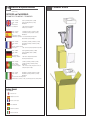
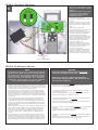
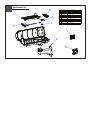
Contents of Box
N O T E : T H E F O L L O W I N G I N S T R U C T I O N S M A I N LY S H O W T H E F C H 3 6 0 C W,
BUT THESE INSTRUCTIONS ARE APPLICABLE TO ALL FCH360 MODELS.
1
2
Twist
Rotate
Lossen and then rotate the wall mount to achieve the
proper orientation.
• Afloje y gire el soporte de pared para conseguir la orientación adecuada.
• Desserrer et puis tourner le support mural pour atteindre le bon sens.
• Lösen und drehen Sie dann die Wandhalterung, um die richtige
Ausrichtung zu erreichen.
• Solte e, em seguida, gire o suporte de parede para alcançar a
orientação adequada.
• Allentare e quindi ruotare il supporto a parete per raggiungere il
corretto orientamento.
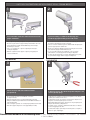
WALL MOUNTING
If you are running a conduit to the housing, first
install the appropriate fitting to the wall mount.
• Si usted está funcionando con un conducto a la cubierta, primero instale
la guarnición apropiada al montaje de la pared.
• Si vous courez un conduit au logement, installez d'abord l'ajustage de
précision approprié sur le bâti de mur.
• Wenn Sie ein Rohr zum Gehäuse laufen lassen, bringen Sie zuerst die
passende Befestigung zur Wandeinfassung an.
• Se você está funcionando uma canalização à carcaça, instale
primeiramente o encaixe apropriado à montagem da parede.
• Se stiate facendo funzionare un condotto all'alloggiamento, in primo
luogo installi il montaggio adatto al supporto della parete.
POLE MOUNTING
3
4
TAB
Attach mount to wall with suitable hardware
(not provided).
If attaching to pole, first break away tabs with pliers and
remove (4) strap plugs.
• Ate el montaje a la pared con el hardware conveniente
(no proporcionado).
• Si atan al poste, el primeros rompen lejos lengüetas con los alicates
y quitan (4) los enchufes de la correa.
• Attachez le bâti au mur avec le matériel approprié (non fourni).
• Si attachant au poteau, les premiers cassent loin des étiquettes avec
des pinces et enlèvent (4) des prises de courroie.
• Bringen Sie Einfassung zur Wand mit der verwendbaren Hardware an
(nicht bereitgestellt).
• Una a montagem à parede com a ferragem apropriada (não fornecida).
• Attacchi il supporto alla parete con fissaggi adatti (non forniti).
• Bei der Befestigung zum Pfosten, brechen erste weg Vorsprünge mit
Zangen und entfernen (4) Bügelstecker.
• Se unindo ao pólo, o primeiros quebram afastado abas com alicates
e removem (4) plugues da cinta.
• Se attaccando al palo, i primi rompono via le linguette con le pinze e
rimuovono (4) la cinghia tappa.
Recommended Hardware for the Mounting Holes: • 5/16” - 18 (or M8 for metric) x minimum 1 ¼” Hex Head Bolt • 5/16” Flat Washer
• 5/16” Lock Washer
6
5
TAB
* Max Strap Width: 0.75”
Attach mount to pole with suitable hardware
(not provided).
• Ate el montaje al poste con el hardware conveniente (no proporcionado).
• Attachez le bâti au poteau avec le matériel approprié (non fourni).
• Bringen Sie Einfassung zum Pfosten mit der verwendbaren Hardware an
(nicht bereitgestellt).
• Una a montagem ao pólo com a ferragem apropriada (não fornecida).
• Attacchi il supporto al palo con fissaggi adatti (non forniti).
Hinge housing away from mount by loosening (2)
rear screws.
• Abisagre la cubierta lejos del montaje aflojando (2) los tornillos
posteriores.
• Articulez le logement à partir du bâti en desserrant (2) les vis arrière.
• Lagern Sie Gehäuse weg von Einfassung schwenkbar, indem Sie (2)
hintere Schrauben lösen.
• Articule a carcaça longe da montagem afrouxando (2) os parafusos
traseiros.
• Alloggiamento della cerniera a partire dal supporto allentando (2) viti
posteriori.
7
Run cables through mount either by conduit input or through the back of the mount.
• Funcione con los cables montan a través por el conducto entrado o a través de la parte posterior del montaje.
• Courez les câbles montent à travers par le conduit entré ou par le dos du bâti.
• Laufen lassen Sie Kabel anbringen durch entweder durch das eingegebene Rohr oder durch die Rückseite der Einfassung.
• Funcione cabos montam completamente pela canalização entrada ou através da parte traseira da montagem.
• Faccia funzionare i cavi attraverso montano dal condotto immesso o tramite la parte posteriore del supporto.
8
9
Pass cables through wiring membranes
(use screwdriver to pierce).
Hinge the housing closed and tighten (2) rear screws.
. • Pase los cables a través de las membranas del cableado
(el destornillador del uso a perforar) .
• Passez les câbles par des membranes de câblage
(le tournevis d'utilisation à percer).
• Führen Sie Kabel durch Verdrahtungsmembranen
(zu durchbohren der Gebrauchschraubenzieher) .
• Passe cabos através das membranas da fiação
(a chave de fenda do uso a perfurar).
. • Abisagre la cubierta cerrada y apriete (2) los tornillos posteriores.
• Articulez le logement fermé et serrez (2) les vis arrière.
• Lagern Sie das geschlossene Gehäuse schwenkbar und ziehen Sie
(2) hintere Schrauben fest.
• Articule a carcaça fechado e aperte (2) os parafusos traseiros.
• Munisca l'alloggiamento di cardini chiuso e stringa (2) viti posteriori.
• Passi i cavi tramite le membrane dei collegamenti
(cacciavite di uso da perforare).
10
11
TAB
TAB
Open housing lid.
Remove camera tray by squeezing tabs together.
.• Abra la tapa de la cubierta.
.• Quite la bandeja de la cámara exprimiendo lengüetas juntas.
• Ouvrez le couvercle de logement.
• Enlevez le plateau d'appareil-photo en serrant des étiquettes ensemble.
• Öffnen Sie Gehäusekappe.
• Entfernen Sie Kamerabehälter, indem Sie zusammen Vorsprünge
zusammendrücken.
• Abra a tampa da carcaça.
• Apra il coperchio dell'alloggiamento.
• Remova a bandeja da câmera espremendo abas junto.
• Rimuova insieme il vassoio della macchina fotografica comprimendo le
linguette.
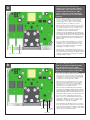
12
- ALIGN LENS -
Spacer
- TOP VIEWDetail
Mount camera with ¼-20 hardware. Position the lens as shown and center with the spacers as needed, confirm
tabs are securely snapped into place. NOTE: Take care not to scratch dome with lens case.
• Monte la cámara con ¼ -20 hardware. Coloque el lente como se muestra y centro con los espaciadores según sea necesario,
confirmar pestañas estén bien encajados. NOTA: Tenga cuidado de no rayar cúpula con estuche.
• Montage de la caméra avec ¼ -20 matériel. Positionnez l'objectif dans le centre et avec les entretoises au besoin,
confirmer onglets sont correctement enclenché. REMARQUE: Veillez à ne pas rayer dôme avec étui à lentilles.
• Mount Kamera mit ¼ -20 Hardware. Positionieren Sie das Objektiv wie abgebildet und in der Mitte mit den Abstandshaltern wie nötig,
werden sicher einrastet bestätigen Registerkarten. HINWEIS: Achten Sie darauf, Kuppel mit Linsenbehälter kratzen.
• Suporte de câmera com ¼ de hardware -20. Posicione a lente como mostrado e centro com os espaçadores, conforme necessário,
confirme guias são bem encaixada no lugar. NOTA: Tome cuidado para não arranhar cúpula com lente caso.
• Montare con fotocamera ¼ -20 hardware. Posizionare la lente come mostrato e centro con i distanziali, se necessario,
verificare le schede siano correttamente scattati in posizione. NOTA: Fare attenzione a non graffiare cupola con portalenti.
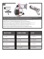
INPUT POWER
CAMERA POWER
GO TO
⇒
24Vac
⇒
24Vac
⇒
SECTION A
⇒
12Vdc
⇒
12Vdc
⇒
SECTION B
⇒
24Vac
⇒
12Vdc
⇒
SECTION C
⇒
PoE (30W)
⇒
PoE (30W)
⇒
SECTION D
SECTION A: 24Vac Input for 24Vac Camera
A
SHUNTS
- Terminate power and data lines.
- Install shunts on “24Vac” jumpers as shown.
- Power output to camera will be 24Vac.
• Termine las líneas de la energía y de datos.
- Instale la desviación en el puente “24Vac” como se muestra.
- La salida de energía a la cámara será 24Vac.
• Terminez les lignes de puissance et de données.
- Installez le shunt sur le pullover « 24Vac » comme montré.
- Le rendement de puissance à l'appareil-photo sera 24Vac.
• Beenden Sie Energie und Datenleitungen.
- Bringen Sie Shunt auf Überbrücker „24Vac“ wie gezeigt an.
- Abgabeleistung zur Kamera ist 24Vac.
• Termine linhas do poder e de dados.
- Instale a derivação na ligação em ponte “24Vac” como
mostrada.
- A saída de poder à câmera será 24Vac.
• Termini le linee di dati e di potere.
- Installi lo shunt sul ponticello “24Vac„ come indicato.
- L'output di forza motrice alla macchina fotografica sarà 24Vac.
SECTION B: 12Vdc Input for 12Vdc Camera
B
SHUNTS
- Terminate incoming voltage as shown.
- Install shunts on “12Vdc” jumpers as shown.
- Power output to camera will be 12Vdc.
• Termine el voltaje entrante como se muestra.
- Instale la desviación en el puente “12Vdc” como se muestra.
- La salida de energía a la cámara será 12Vdc.
• Terminez la tension entrante comme montrée.
- Installez le shunt sur le pullover « 12Vdc » comme montré.
- Le rendement de puissance à l'appareil-photo sera 12Vdc.
• Beenden Sie ankommende Spannung wie gezeigt.
- Bringen Sie Shunt auf Überbrücker „12Vdc“ wie gezeigt an.
- Abgabeleistung zur Kamera ist 12Vdc.
• Termine a tensão entrante como mostrada.
- Instale a derivação na ligação em ponte “12Vdc” como
mostrada.
- A saída de poder à câmera será 12Vdc.
• Termini la tensione ricevuta come indicata.
- Installi lo shunt sul ponticello “12Vdc„ come indicato.
- L'output di forza motrice alla macchina fotografica sarà 12Vdc.
SECTION C: 12Vac Input for 12Vdc Camera
C
- Terminate incoming 24Vac on board.
- Shunts should be installed on 24Vac
jumpers.
- Terminate the 12Vdc leads (coming
from power supply mounted on
husing lid) into corresponding
terminals on camera.
Y.
• Terminar 24Vac entrantes a bordo.
- Las derivaciones se deben instalar en los puentes
de 24 VAC.
- Terminar los conductores de 12 VCC (procedente
de la fuente de alimentación montada en la tapa
Husing) en los terminales correspondientes de la
cámara.
W
)
P
UR
PL
UR
24Vac
(P
P.
• Beenden Sie eingehende 24Vac an Bord.
- Shunts sollte auf 24Vac Jumper installiert werden.
- Beenden Sie die Leads 12Vdc (kommend von der
Stromversorgung auf Hüsing Deckel montiert) in
entsprechende Endgeräte vor der Kamera.
IN
E)
(Y
LO
EL
• Mettre fin à 24Vac entrants à bord.
- Shunts doivent être installés sur les cavaliers 24Vac.
- Terminer les fils 12Vdc (en provenance de
l'alimentation monté sur Hüsing couvercle) dans les
terminaux correspondants sur l'appareil photo.
• Encerra 24Vac entrada a bordo.
- Shunts deve ser instalado em jumpers 24VAC.
- Terminar as ligações 12VDC (proveniente de fonte
de alimentação montada no Hüsing tampa) em
terminais correspondentes na câmera.
• Termina 24Vac in arrivo a bordo.
- Shunt deve essere installato su ponticelli 24Vac.
- Terminare i cavi 12Vdc (provenienti dalla rete di
alimentazione montato su husing coperchio) nei
terminali corrispondenti sulla macchina fotografica.
Red (+)
{
Black (-)
Power to Camera (12Vdc)
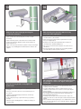
SECTION D: PoE 30W Input for 30W Camera
WARNING!
NOTE:
•
•
•
•
•
To maximize power for the camera and heater option, the unit
requires that you calibrate the enclosure. During calibration,
the onboard processor intelligently determines the maximum
safe power output of the midspan, and ensures that the
enclosure does not exceed that limit. Once calibration is
complete the required values are stored in permanent
memory, with no additional calibration required.
• The heater and blower will not start for 60 seconds
after power is applied to the product.
Para maximizar la potencia de la opción de cámara y la calefacción, la unidad requiere
que calibre la caja. Durante la calibración, el procesador de a bordo determina de forma
inteligente la potencia máxima seguridad del centro de la luz, y asegura que el recinto no
exceda de ese límite. Una vez que la calibración se ha completado los valores requeridos
se almacenan en la memoria permanente, sin calibración adicional.
•
The heater and blower will not start for 60 seconds after power is applied to the product.
•
Wait for the camera to completely boot up before pressing the calibration button. This
will allow for the most accurate calibration.
Pour maximiser la puissance de l'option appareil photo et le chauffage, l'unité exige
que vous calibrer l'enceinte. Lors de l'étalonnage, le processeur embarqué détermine
intelligemment la puissance de sortie maximale de sécurité de l'injecteur, et veille à ce
que l'enceinte ne dépasse pas cette limite. Une fois l'étalonnage est terminé, les valeurs
requises sont stockées dans la mémoire permanente, sans étalonnage supplémentaire
n'est nécessaire.
•
Le chauffage et de ventilation ne démarre pas pendant 60 secondes après mise sous
tension est appliquée au produit.
•
Attendez que l'appareil photo à démarrer complètement avant appuyant sur le bouton
d'étalonnage. Cela permettra pour le calibrage le plus précis.
Um Strom für die Kamera und Heizung Option zu maximieren, setzt das Gerät, dass
Sie das Gehäuse zu kalibrieren. Während der Kalibrierung der Onboard-Prozessor
ermittelt intelligent die maximale sichere Leistung der Feldmitte, und sorgt dafür, dass
das Gehäuse nicht überschreitet diese Grenze. Sobald die Kalibrierung abgeschlossen
ist die geforderten Werte im permanenten Speicher abgelegt werden, ohne zusätzliche
Kalibrierung erforderlich.
•
Die Heizung und das Gebläse wird nicht für 60 Sekunden nach dem Einschalten starten,
um das Produkt angewendet wird.
•
Warten Sie, bis sich die Kamera komplett hochfahren, bevor Sie die Kalibrierung Taste.
Dies wird für die genaue Kalibrierung ermöglichen.
Para maximizar a potência para a opção câmera e aquecedor, a unidade exige que você
calibrar o gabinete. Durante a calibragem, o processador de bordo inteligentemente
determina a potência de saída máxima de segurança do midspan, e assegura que o
invólucro não exceder o limite. Uma vez que a calibração é completar os valores
necessários são armazenados na memória permanente, sem calibração adicional
necessário.
•
Aquecedor e soprador A não será iniciado durante 60 segundos após a energia é aplicada
ao produto.
Aguarde até que a câmera completamente arrancar antes de premir o botão de
calibração. Isto irá permitir a calibração mais precisas.
Per massimizzare la potenza per l'opzione della fotocamera e il riscaldatore, l'unità
richiede la calibrazione del contenitore. Durante la calibrazione, il processore a bordo
determina in modo intelligente la potenza massima sicurezza del midspan, e assicura
che la custodia non superi tale limite. Una volta calibrazione è completa dei necessari
valori memorizzati nella memoria permanente, senza calibrazione aggiuntiva richiesta.
•
• Wait for the camera to completely boot up before
pressing the calibration button. This will allow for the
most accurate calibration.
•
•
Il riscaldamento e soffiante non inizierà per 60 secondi dopo l'alimentazione è applicata
al prodotto.
Attendere che la macchina fotografica per avviare completamente a prima di premere il
pulsante di calibrazione. Questo permetterà la taratura più accurata.
D
Connect the network cable from the
midspan to the connector that is labeled
“To Network” connect the camera to the
connector labeled “To Camera”. When
power is applied the “Heat” LED will turn
ON for 5 seconds. 60 seconds the blower
will start.
•
Conecte el cable de red del centro de la luz en el conector
que tiene la etiqueta "Para Red", conecte la cámara al
conector con la etiqueta "Para la cámara". Cuando la
energía se aplica el "calor" LED se encenderá durante 5
segundos. 60 segundos, el ventilador se enciende.
•
Branchez le câble réseau de la mi-portée sur le connecteur
qui est étiqueté «Pour Réseau" connecter l'appareil photo
au connecteur marqué "à la caméra". Lorsqu'une tension
est appliquée la "chaleur" LED s'allume pendant 5
secondes. 60 secondes le ventilateur démarre.
• Schließen Sie das Netzwerkkabel aus dem Midspan an
den Anschluss, die den Namen "Zum Network" schließen
Sie die Kamera an den Anschluss mit der Aufschrift "Zur
Kamera". Wenn die Macht der "Heat" wird angewendet
LED für 5 Sekunden einzuschalten. 60 Sekunden das
Gebläse startet.
• Conecte o cabo de rede do midspan ao conector que
é rotulado de "rede" conectar a câmera ao conector
identificado como "Para Camera". Quando a energia
é aplicada a "Heat" LED irá acender por 5 segundos.
60 segundos, o ventilador começará.
To Network
• Collegare il cavo di rete dal midspan al connettore che
viene etichettato come "alla rete" collegare la fotocamera
al connettore etichettato "Per Camera". Quando il potere
è applicato il "Heat" LED si accende per 5 secondi. 60
secondi il ventilatore si avvia.
To Camera
D
Press the Calibration button for one second.
Both the Test and Heat LED will turn ON.
Once the unit has been successfully
calibrated, the Test and Heat LED will turn
OFF. Once this is complete the Heat LED
will turn ON only if the heater is ON.
•
Pulse el botón de calibración durante un segundo. Tanto la
prueba y el calor se encenderá. Una vez que la unidad ha
sido calibrado correctamente, la prueba y el calor del LED
se apagará. Una vez que se trata de completar el calor se
encenderá sólo si el calentador está encendido.
•
Appuyez sur le bouton d'étalonnage pour une seconde.
Tant le test et la chaleur LED s'allume. Une fois l'appareil
a été étalonné avec succès, le test et la chaleur LED
s'éteindra. Une fois cette opération terminée, la chaleur
LED s'allume que si le chauffage est allumé.
• Drücken Sie die Taste Kalibrierung für eine Sekunde.
Sowohl der Test-und Wärme-LED leuchtet auf. Sobald
das Gerät erfolgreich kalibriert wurde, wird die Test-und
Wärme-LED auszuschalten. Sobald dies abgeschlossen
ist die Wärme-LED leuchtet auf, wenn die Heizung an ist.
• Pressione o botão de calibração para um segundo.
Tanto o teste como calor LED acenderá. Uma vez que
o aparelho foi calibrado com sucesso, o teste e calor
LED apaga-se. Uma vez que este é completar o calor
LED acenderá se o aquecedor está ligado.
Test LED
Calibration
Button
Heat LED
• Premere il pulsante di calibrazione per un secondo. Sia
il test e di calore LED si accende. Una volta che l'unità è
stata correttamente calibrata, il collaudo e calore LED si
spegne. Una volta che questo è completare il calore LED
si accende solo se il riscaldatore è ON.
14
13
Hex tool
After powering your system up, make necessary
focus and camera adjustments.
Adjust the aim of the housing by loosening the
screw on the mount arm.
.• Ajuste la puntería de la cubierta aflojando el tornillo en el brazo
del montaje.
.• Después de accionar su sistema para arriba, haga los ajustes
necesarios del foco y de la cámara.
• Ajustez le but du logement en desserrant la vis sur le bras de bâti.
• Après avoir mis votre système, faites les ajustements nécessaires
de foyer et d'appareil-photo.
• Justieren Sie das Ziel des Gehäuses, indem Sie die Schraube am
Einfassungsarm lösen.
• Nachdem Sie oben Ihr System angetrieben haben, nehmen Sie
notwendige Fokus- und Kamerajustagen vor.
• Ajuste o alvo da carcaça afrouxando o parafuso no braço da montagem.
• Após ter psto seu sistema acima, faça ajustes necessários do foco
e da câmera.
• Registri lo scopo dell'alloggiamento allentando la vite sul braccio del
supporto.
15
Close the housing lid and securely tighten the
(2) lid screws.
• Dopo la potenza del vostro sistema in su, procedi alle registrazioni
necessarie della macchina fotografica e del fuoco.
16
The camera tray can be securely locked into place with
the provided 3.5 x 7mm screw. Tighten it through the
rear tray tab.
.• La bandeja de la cámara se puede trabar con seguridad en lugar con el
.• Cierre la tapa de la cubierta y apriete con seguridad (2) los tornillos
•
• Fermez le couvercle de logement et serrez solidement (2) les vis
de couvercle.
•
• Schließen Sie die Gehäusekappe und ziehen Sie sicher die (2)
Kappenschrauben fest.
•
de la tapa.
• Feche a tampa da carcaça e aperte firmemente (2) os parafusos
da tampa.
• Chiuda il coperchio dell'alloggiamento e saldamente stringa (2) il
coperchio avvita.
•
tornillo proporcionado de 3.5 x de 7m m. Apriétela a través de la
lengüeta posterior de la bandeja.
Le plateau d'appareil-photo peut être solidement fermé à clef sur
l'endroit avec la vis fournie de 3.5 x de 7mm. Serrez-le par l'étiquette
arrière de plateau.
Der Kamerabehälter kann in Platz mit der zur Verfügung gestellten 3.5 x
7mm Schraube sicher verriegelt werden. Ziehen Sie ihn durch den
hinteren Behältervorsprung fest.
A bandeja da câmera pode ser firmemente fechado no lugar com o
parafuso fornecido de 3.5 x de 7mm. Aperte-a através da aba traseira da
bandeja.
Il vassoio della macchina fotografica può essere saldamente bloccato nel
posto con la vite fornita di 7mm x di 3.5. Stringalo attraverso la linguetta
posteriore del vassoio.
17
18
Wire Gauge
5.5
10
20
30
40
50
60
70
80
If your housing has a sunshield, adjust it for your
particular lighting conditions by loosening (2) screws.
.• Si su cubierta tiene un sunshield, ajústelo para que haya sus condiciones
de iluminación particulares aflojando (2) los tornillos.
• Si votre logement a un sunshield, ajustez-le à vos états d'éclairage
particuliers en desserrant (2) des vis.
• Wenn Ihr Gehäuse ein sunshield hat, stellen Sie es auf Ihre bestimmten
Beleuchtungzustände ein, indem Sie (2) Schrauben lösen.
• Se sua carcaça tem um sunshield, ajuste-o para suas condições de
iluminação particulares afrouxando (2) os parafusos.
• Se il vostro alloggiamento ha un sunshield, registrilo per ottenere le
vostre condizioni di luce particolari allentando (2) avvita.
!
,5
22
Total vA
consumed
ft
,75
20
1,0
18
1,5
16
2,5
14
400
m
120
600
960
121
182
292
180
300
480
800
6
10
-
-
2
MM
AWG
1300
36.5
54.9
91.4
146
243
396
86
141
225
358
571
905
1440
27.1
43.0
68.6
109
174
275
438
65
90
130
225
350
525
830
19.8
27.4
39.6
68.6
106
160
252
44
70
112
179
285
452
720
13.4
21.3
34.1
54.6
86.9
138
219
56
90
143
228
362
576
35
10.6
17.1
27.4
43.6
69.5
110
175
29
47
75
119
190
301
480
9.4
14.3
22.9
36.2
57.9
91.7
146
40
64
102
163
258
411
8.8
12.2
19.5
31.1
49.7
78.6
125
34
55
85
140
215
340
25
31
7.6
10.3
16.8
25.9
42.7
65.5
103
These are recommended maximum distances
for 24VAC with a 10% voltage drop.
• Éstos se recomiendan las distancias máximas para
24VAC con una caída de voltaje del 10%.
• Ceux-ci sont recommandés des distances maximum
pour 24VAC avec une chute de tension de 10%.
• Diese werden maximale Abstände für 24VAC mit
einem 10% Spannungsabfall empfohlen.
• Estes são recomendados distâncias máximas para
24VAC com uma queda de tensão de 10%.
• Questi sono suggeriti distanze massime per 24VAC con
una differenza de potenziale di 10%.
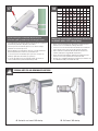
SPECIAL NOTE FOR 360 VIEWING APPLICATIONS
A. Horizontal mast mount 360 viewing
4
12
B. Wall mount 360 viewing
Replacement Parts
FCH11
3
1
4
5
#
1
2
Part Number
RPVL3948
RPVL3950
Description
FCH Camera Tray
FCH Heater + Bracket
3
RP76VL2016
FCH 12VDC/24VAC PCB
4
RPFD080
12VDC 40mm Fan
5
RPVL3953
Cable Membrane (0.60" hole)
6
RPFTM2425G
FCH Wall Mount Assembly
7
RPFCH11HP
FCH Hardware Packet
8
RP71VLBL09
Outdoor Rated Fan (Thermiq only)
N/S
RP76VL2018
FCHQ 12VDC/24VAC PCB
N/S
RP76VL2023
FCHQ PoE PCB
2
7
6
8
Product Registration/Warranty
Thank you for choosing Moog Videolarm. We value your patronage and are solely committed to providing you with the highest
quality products available and superior customer service. Should a problem arise, rest assured that Moog Videolarm stands behind its products by offering impressive 3 Year and 5 Year warranties, depending on the product
purchased. See full warranty details at www.moogvideolarm.com/technical-support/warranty-plan/
Register Your Products Online
Please take a few moments to register your purchase via the Online Product Registration Form at:
www.moogvideolarm.com/technical-support/product-registration
Register your recent Moog Videolarm purchase and benefit from the following:
• Simple and Trouble-Free RMA process
• Receive product updates, and special promotion
• Eliminate the need to archive original purchase documents:
Receipts, Purchase Orders, etc…