1
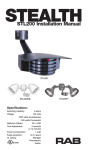
Specifications:
Switching Capacity:
8 amps
Voltage:120 volts
Installation Manual
The STEALTH 360 is the most reliable
and technically advanced motionactivated light control ever
produced. This technical manual is
written for electrical professionals
who wish to maximize the
performance and reliability of this
superb sensor.
Protection Pattern:
180º forward
360º below and to the sides
Time Adjustment:
5 seconds to 12 minutes
Power Consumption:
1 watt
Surge protection:
6000 volts
RAB welcomes your questions or
comments.
Please call 888 722 1000 or email
[email protected].
Thank you for purchasing a RAB sensor.
Cautions:
TURN OFF ALL POWER AT CIRCUIT BREAKER/FUSE PANEL
STL360H
STL360HBW
STL3FFLED18
■■ Read entire Installation Manual before proceeding.
■■ All wiring should comply with local electrical codes and
requires a qualified electrician.
■■ The total lighting load connected to STL360 must not exceed (1000 watts
incandescent, 250 watts fluorescent). To switch more wattage, an electrician can install a relay.
■■ Line Carrier Remote Control Systems such as X-10, Leviton or Radio Shack
are incompatible with sensors and may cause false activations.
■■ Do not install sensors on a circuit that feeds motor loads such as kitchen
appliances, HVAC equipment, washer/dryer, or garage door openers.
■■ Sensor functions best when the direction of expected
movement is across its detection pattern, not towards the sensor.
Mount 6’-10’ high for optimum range and detection.
How Does the Super Stealth 360 Work?
The STL360’s infrared sensor “ sees” temperature changes caused by the
motion of people or cars within its protection zone and turns on lights
automatically. It welcomes visitors and may deter intruders.
Total coverage. Two sensors in one.
Two powerful detectors combine to
give the STL360 “Can’t Miss” Detection:
180º long forward range (180º x 60’)
plus superb 360º detection below and
to all sides.
How long do the lights stay on?
Lights remain on as long as there is movement within the
protection zone. Once the zone is vacated lights can be adjusted to remain
on approximately 5 seconds up to 12 minutes. Since the lights are on only
when needed, and the sensor uses only one watt. The Stealth is extremely
energy efficient.
Can outdoor lights still be turned on with the light switch?
Yes. STL360 can be controlled by a conventional indoor switch or circuit
breaker. STL360 operates in the auto mode unless changed. Lights can be
turned on or off manually at night only with the Manual Override Mode..
Wall Switch Manual Override: (to keep lights on)
How do the scanning LED detection indicators work?
Scanning LEDs serve as a
deterrent by indicating a
security device in operation. They
also show the STL360’s mode of
operation.
Automatic Mode: When the STL360
is “On Guard” in Auto mode, three
red LEDs scan
continuously day and night, except
during detections
(at which time the controlled lights
will go on and LEDs will be off ).
Flip the switch twice slowly (off-on-off-on) within 1–2 seconds. If you set this
during the sensor will become “ready” for the Manual Override Mode and will
start Manual Override at dusk.
Evening Timer: (to keep lights on, and is repeated every night): Flip the
switch three times slowly (off-on-off-on-off-on) within 1½ – 3 seconds. You
can set this during the day and the Evening Timer Mode will begin at dusk.
To Resume Automatic Mode:
“On Guard Auto Mode”
LEDs scan continuously back & forth
Switch power off for at least 10 seconds, then back on.
Will STL360 detect animals?
STL360 may detect large animals. Having animals trigger the sensor can give
property a “lived-in” look. However, you can limit animal detection by turning
down the sensitivity knob and/or placing the blinders provided on the lower
part of the forward lens.
Test Mode: When the sensor is in
“Test Mode” all of the LEDs will be
off.
Manual Override Mode:
“Test Mode” all LEDs off
When the sensor is ready for
“Manual Override Mode” the middle
LED will be on steady.
Evening Timer Mode:
When the sensor is ready for “Evening Timer Mode Mode” the middle
LED will be blink.
STEALTH-IN-1114
1
Middle LED on steady is
Manual Override Mode
Middle LED blinking is
Evening Timer Mode
How do you make
adjustments to the sensor?
EVENING
TIMER
Use the adjustment tool
provided, or a screwdriver with a 1/8”
wide blade, to adjust the controls
on the front of the sensor. (see page
11-12)
1
2
8 HRS
5 SECS
TIME
12 MINS
SENS
–
+
Choosing a Location
The best location is where the sensor can “see” all paths of movement. The
sensor may be wall or soffit mounted.
As distance from the sensor increases, larger movement will be required for
detection. For instance, at 10 feet, a half step will be enough, while at 50 feet
several steps will be necessary for detection.
How large an area does STL360 protect?
Two powerful detectors combine to give the STL360 180ºx60’ long forward
range plus superb 360º downward detection below and to all sides.
Difficult Locations:
Sensor may be triggered by unwanted movement or heat source, such
as a swaying tree, road traffic, dryer
vent, swimming pool or hot tub.
To improve performance in
difficult locations:
• Reduce sensitivity by turning the
SENS knob counterclockwise,
EVENING
TIMER
1
8 HRS
5 SECS
TIME
SENS
–
12 MINS
and/or...
• Mask lens in the direction of the
unwanted movement or heat
source using the lens mask provided or opaque tape.
side view
20’
6-10’
mask
Mounting Stability
60’
• Mount sensor on stable surface.
Do not mount on a tree or pole
that will move in the wind.
wrong
• Make sure sensor and lights are
mounted firmly. If they move
when touched, tighten all screws.
60’
Mounting Height
Mounting at 6-10’ above the ground allows maximum range. If the sensor is
mounted above 15’ high, the usable range is reduced.
Light vs. Sensor Position
• Make sure heat from lights is not
triggering sensor. Sensor must be
located below and as far away as
possible from its lights.
OK!
6-10’
60’
Maximum Range
STEALTH-IN-1114
wrong
40’
Reduced Range
3
4
+
Choosing a Location
Locations Near Roads
Cars and passing traffic may activate the sensor if it is aimed at the road.
To Improve Performance in Difficult Locations:
• Reduce sensitivity by turning the SENS knob counterclockwise,
EVENING
TIMER
1
8 HRS
5 SECS
TIME
SENS
–
12 MINS
Better detection after
“micro adjustment”
Choose a Protected Location
Mount sensor in protected area.
The more protected the mounting
location, the less chance of lights
turning on occasionally during
rain, snow and windstorms. This
could happen because the sensor
is detecting dramatic changes in
temperature.
OK!
20’
safety
zone
STEALTH-IN-1114
More sensitive
If the sensor is located over a
pathway so all movement is directly
toward it, range may appear limited.
“Micro Adjust” sensor by moving
sideways 1/4” or so, which may
reposition the zones enough to
allow earlier detection.
Lens Mask
(included)
Mount Level
The sensor should be mounted level
from side to side and pointed at the
area where you desire coverage. If
tilted, part of the detection zone
may be high in the air over people’s
heads.
WRONG
WRONG
OK!
5
Less
sensitive
+
• Mask lens in the direction of
the traffic using the lens mask
provided or opaque tape.
(Lens Mask can be broken
along lines to desired size)
• Make sure that sensor is not aimed
at traffic. The sensor should
be aimed down so that the
maximum range of the sensor
ends at least 20’ from the road.
This will avoid detection of
passing trucks and cars, or the
air currents they create.
Locate for Movement Across Pattern
Check that movement is not directly
towards sensor. Sensor will see
movement ACROSS its pattern
move quickly. Check that movement far away and directly towards
sensor is not entirely within one
zone. To fix, change the sensor
angle or location.
6
OK!
STL360 Kit Assembly and Wiring
STL360H
1. Attach the Universal Mounting bar with the screws provided to the junction box. If you are attaching your STL360 kit to a surface mount weatherproof box, you must use with the metal mouting plate with gasket.
STL360HBW
STL360 floodlight kits come pre-wired and assemble on the RAB CU4 EZ
plate, allowing for mounting on round, rectangular or octagonal surface or
recessed boxes.
Mounting
CU4 EZ Plate
Bar Screws
Gasket
Insert
close-up
plug in
unused
hole
Center
Screw
Universal
Mounting
Bar
Finishing
Cap
Hook
O-Ring
Gasket
Gasket &
Surface Plate
Wiring
Red pigtail is only used to switch
remote or additional fixtures.
Red
(pigtail)
Red
Black
Black
Power In
White
Ground
STEALTH-IN-1114
7
White
Ground
2. Easy Wiring Tip:
Use the “S” shaped Hands
Free Hanging Hook to hold
the CU4 EZ Plate during wiring.
Hands Free
Hanging
Hook
Hood rests
in notch on
crossbar
3. Bring power leads and sensor
kit leads through holes in
gasket and plate into
junction box.
4. Strip 1/2” of insulation from
all leads.
CU4 EZ Plate
5. Attach ground wire(s) to junction box grounding screw.
Connect as shown in wiring diagram on page 7.
6. Twist on wire nuts. Secure with electrical tape.
7. Align CU4 EZ Plate and metal surface plate with gasket (for use with
surface mounted junction boxes) to ensure proper seal. Tighten CU4 EZ
Plate center screw (make sure O-Ring gasket is on the screw) to attach
CU4 EZ Plate to the box.
8. Insert plastic Finishing Cap in the center of the CU4 EZ Plate for a weatherproof seal.
9. Use silicone sealant around plate and all opening to ensure a weather
proof seal. Seal all unsued conduit entries on surface junction box.
10. Screw in light bulbs. Turn on power. Conduct walk test to adjust
sensor response (see page 15).
8
STL360 Assembly and Wiring
Multiple Sensors
■■
To install a STL360 Sensor with separately purchased floodlights,
start at #1
■■
To install STL360 Pre-wired Floodlight Kits, see page 7.
Multiple sensors may be wired together, but doing this will make problems
difficult to troubleshoot. Single sensors that control their own lights will give
a more accurate location of movement and trouble-free operation.
1. Screw the threaded arms of each floodlight into the RAB CU4 EZ Plate.
(See diagram on page 7)
2. Screw the threaded arm of the sensor into the bottom hole of the EZ
Plate. Sensor should be below and as far away from the floodlights as
possible.
3. Attach the Universal Mounting bar with the screws provided to the
junction box. If you are attaching your STL360 kit to a surface mount
weatherproof box, you must use the metal mounting plate with gasket.
4. Use the “S” shaped Hands Free Hanging Hook to hold the EZ Plate
during wiring.
Multiple Fixtures
Multiple fixtures may be wired
to a single sensor.
To handle loads greater than
1000 watts, a qualified
electrician should install a relay.
5. Bring power leads and sensor kit leads through holes in gasket into
junction box.
6. Attach ground wire(s) to junction box grounding screw.
7. Position CU4 EZ Plate and metal surface plate with
gasket (required for mounting on surface junction boxes) (see pg #7).
8. Strip 1/2” of insulation from all leads.
Connect as shown in wiring diagram.
9. Twist on wire nuts.
Secure with electrical tape.
10. Make sure all unused openings
in CU4 EZ Plate are closed
with plugs (provided).
11. Use silicone sealant around plate and all openings to ensure a weather
proof seal. Seal all unsued conduit entries on surface junction box.
Power Quality
It is not recommended to install sensors on a circuit that also feeds motor
loads such as HVAC equipment, kitchen appliances, or garage door openers.
The Stealth circuit is surge and transient protected to IEC specifications.
However, if voltage varies significantly from 120 volts, the sensor may
malfunction. This may occur on circuits with motor loads.
12. Screw in light bulbs. Turn on power.
13. Conduct walk test to adjust sensor response (see page 15).
STEALTH-IN-1114
9
10
Adjusting the Settings
TIME
EVENING TIMER
EVENING
TIMER
1
8 HRS
5 SECS
TIME
SENS
–
12 MINS
EVENING
TIMER
+
Sets the time that lights will remain on after the detection zone is vacated.
Adjustable from approximately 5 seconds to 12 minutes. The factory setting
is 12 minutes.
PHOTOCELL
EVENING
TIMER
1
8 HRS
5 SECS
TIME
SENS
–
12 MINS
+
For night-only operation, turn the knob completely counterclockwise to (to
the MOON symbol). For 24-hour operation turn the knob all the way clockwise to the MOON/SUN symbol. Adjust counterclockwise to have the sensor
come on later at dusk, clockwise to have it come on earlier. The Factory
Setting is Night-only (MOON). If you set Evening Timer while set to 24 hour
operation Evening Timer will begin immediately after flipping switch.
1
8 HRS
5 SECS
TIME
SENS
12 MINS
EVENING
TIMER
1
8 HRS
5 SECS
TIME
SENS
–
12 MINS
Increases or decreases the resposiveness and range of the
sensor (adjustable from 30% to 100%). The Factory Setting is 100%.
STEALTH-IN-1114
11
+
+
The STL360 provides an alternative to normal motion-activated lighting. The
EVENING TIMER can keep lights on continuously - without motion - for 1 to
8 hours after dusk. This is great for evening activities requiring continuous
light. During vacations the EVENING TIMER provides a “lived-in” look by
simulating an occupant turning lights on at dusk, and then off at bedtime.
To activate the EVENING TIMER, flip the wall switch controlling the sensor
three times slowly (off-on-off-on-off-on) within 3 seconds. If you activate
the EVENING TIMER during daytime, the middle LED should start blinking,
indicating that the EVENING TIMER will start when dusk is detected.
Choose the length of time you want continuous lighting. For example, if you
set the EVENING TIMER to “8”, the sensor will keep lights ON continuosly for 8
hours after dusk. Once 8 hours have passed, the sensor will revert to motion
activated mode. At dawn, the photocell will detect light and prevent lights
from turning on during the daytime. The Evening Timer Mode will continue
until you de-activate it.
If you do not want to use the
EVENING TIMER, do NOT flip the
switch 3 times, as described above.
SENSITIVITY
–
RAB
STEALTH360
To de-activate the EVENING TIMER,
switch the sensor OFF for at least
10seconds, then ON again. Sensor
will be in Automatic Mode. (After
completing the 30 sec warm-up period)
You can affix this label (right),
provided, to your indoor light
switch plate for easy reference.
12
To Keep Lights On:
Switch off-on-off-on
within 2 seconds. Resets
to Auto Mode at dawn.
To Set
Evening Timer:
To keep lights on for
1-8 hours after dusk, set
the Evening Timer knob
on the sensor, then flip
this switch off-on-off-on
within 3 seconds.
To Resume
Auto Mode:
Switch off for 10
seconds, then back on.
Sensor Modes
MANUAL OVERRIDE MODE
AUTOMATIC MODE
Lights will turn on when there
is movement within the detection zone after dusk.
“On Guard Auto Mode”
LEDs scan continuously back and forth
EVENING TIMER MODE
Keeps lights on for 1-8 hours after dusk. Sensor then reverts to Automatic
Mode until dawn. If you set the Evening Timer Mode during daylight, the
sensor will be prepared to turn on at dusk and remain on for the number of
hours you set. When the sensor is in “Ready for Evening Timer
Mode”, the middle LED will
blink 3 times, pause and repeat.
Set the Evening Timer by
flipping the switch that operates
the sensor 3 times within
3 seconds (off-onoff-of off-on).
“Ready for Evening Timer Mode”
Middle LED blinks
EVENING
TIMER
8 HRS
5 SECS
TIME
By flipping the switch that operates the sensor twice (off-on-off-on) within
2 seconds you will override the sensor to keep lights on continuously until
dawn.
If you set the Manual Override Mode during daylight, the sensor will be
prepared to turn on at dusk and remain on until dawn. This is a handy feature
if you leave home for the day and you want the lights on to greet you when
you return. When the sensor is in “ Ready for Manual Override Mode” the
middle LED will be on.
“Ready for Manual Override Mode”
Middle LED on
SENS
–
+
TEST MODE
The Test Mode will allow you to test the sensor during the day regardless of
the photocell setting. To enter Test Mode, turn time setting to 5 sec on the
unit. Turn power off for 10 secs then back on. There is a 30 second warm-up
period, then the Test Mode starts. During the warm-up, the lights stay on
continiously and LEDs are off. During Test Mode the LEDs remain off. The
sensor will stay in Test Mode until the detection zone is vacated for one
minute.
1
The STL360 has a “protected” Manual Override that requires a double-flip of
the light switch so momentary power problems do not interfere with normal
sensor operation.
12 MINS
TO RESUME AUTOMATIC MODE
Switch OFF the power for at least 10 seconds, then turn it ON again. Sensor
will reset to Automatic Mode after completing the warm-up period.
DAYTIME (24-HOUR) OPERATION OF MANUAL OVERRIDE
If you set Manual Override while set to 24 hour operation, lights will come on
and remain on continously.
Lights will not turn off at dawn.
During the Test Period, the sensor will keep lights on for
5 seconds each time it detects movement in its detection zone. Perform the
walk test and make any adjustments needed. Vacate the detection zone for
one minunte to end Test Mode. Scanning LEDs will appear when test mode
ends. Set back to desired time setting after testing complete.
STEALTH-IN-1114
13
14
Walk Testing
Technical Tips:
Lights Do Not Turn Off
STL360’s full coverage pattern reduces the need for aiming and adjustment.
The purpose of the Walk Test is to check and adjust the coverage pattern. The
STL360 must be manually set into Test Mode (see pg 13).
1. Make sure that the sensor is not in Manual Override Mode. Turn sensor
OFF for 10 seconds, then back ON. The Sensor will be go through 30
second warm up period where the lights are one then will go into
Automatic Mode with lights off and ready to detect movement.
To enter Test Mode:
Turn Time setting to 5 seconds and turn off sensor for 10 seconds. After a
warm up period of 30 seconds the LEDs will be off.
2. Make sure that the sensor is not in Evening Timer Mode. Turn power OFF
for 10 seconds (see # 1).
1. Aim the sensor at the traffic
pattern you want to detect.
Sensor will detect any
movement ACROSS its
pattern most effectively.
2. Start outside the pattern and
walk across the pattern until
the lights go on. As distance from the sensor increases, it will take more
movement to be detected.
3. Adjust sensor aiming as necessary to improve coverage. Make sure sensor is level.
4. Sensitivity may be decreased with the SENS knob to detect a limited area
or if the sensor is being activated by wind, foliage, traffic or animals, or
increased to cover a larger area. [See pg. 11-12 to adjust sensor settings.]
The lens mask can also be used to drastically reduce coverage, or allow
undetected movement from some directions.
5. STL360 is factory set for night only operation. For 24 hour operation, turn
the photocell control completely toward the SUN/MOON setting. Turn
counter clockwise to have the sensor come on later at dusk, clockwise to
have it come on earlier.
6. Repeat steps 1-5 until you are satisfied with coverage. Vacate the
detection zone for 1 minute and then turn the settings back to desired
time delay. Your sensor is now ready for operation.
Easy Installation & Product Help
©2014 RAB LIGHTING Inc.
Northvale, New Jersey 07647 USA
Tech Help Line
Call our experts 888 RAB-1000
STEALTH-IN-1114
rabweb.com
Visit our website for product info
15
email
Answered promptly [email protected]
3. Make sure sensor is not aimed at or mounted over something that
would move or change temperature such as waving branches, water, air
conditioners, windows or heating vents even on neighboring property.
You can test for infrared sources in the area by placing a box or bag over
the sensor. Put sensor into test mode. Lights should stay off. Wave your
hand inside bag in front of sensor. Lights should go on and then time out.
If sensor operates
properly when covered, check items # 4-8.
Problem: Sensor is triggered by
unwanted movement or heat source.
Solution:
(1) Aim sensor away from movement, or
(2) Mask lens in the direction of the source
(3) Lower sensitivity control setting
4. Make sure sensor and lights are mounted
firmly and do not move even slightly when
touched. If they move, tighten all screws.
5. Make sure sensor is not mounted on an
unstable object such as a tree or pole
that will move in the wind.
Problem: Movement of tree triggers sensor.
Solution: Mount on stable surface.
6. Was sensor wired hot (with power on etc)?
If so, circuitry may have been damaged.
7. Make sure sensor is not aimed within 20 feet of a road.
Problem: Passing cars activate sensor.
Solution: A 20 foot safety zone and lower sensitivity are
recommended to avoid activation from passing cars.
8. Make sure heat from lights is not
triggering sensor. Make sure the
sensor is below and as far as
possible away from lights.
16
Technical Tips:
Lights Turn On and Off Inappropriately
Technical Tips:
Lights Do Not Turn On
1. Make sure the sensor is installed on its own dedicated circuit, free of
motor loads such as HVAC equipment, kitchen appliances or garage
door openers.
1. Check that lamps and fixtures work. Compare wiring to the wiring diagram in this manual. Check that the power is on.
2. It is not recommended to wire sensors in parallel. More than one sensor
wired together makes them difficult to troubleshoot. Disconnect
multiple sensors and test separately.
2. If installing during daylight, LED will go into automatic mode after 30
sec warm up period and will not work during daylight if the photocell is
turned to the night only position (moon symbol).
3. Keep all people completely out of the detection pattern to make sure
the sensor is not detecting them.
If you require a test mode, turn time setting to 5 seconds and turn the
power off at least 10 seconds and back on again.
4. Make sure sensor is located below and
as far as possible from its lights. Heat from
the lights may trigger the sensor.
If you require the sensor to operate
EVENING
both day and night, turn
the
TIMER
SUN/MOON control knob
1
5 SECS
clockwise to the
sun8 HRS
and moon
symbol.
Solution: Move sensor below and away
from the lights.
OK!
WRONG
5. Make sure lights are not reflecting back into sensor. Check for white or
reflective surfaces close to the sensor.
Solution: Aim sensor away from reflective
objects, or move the objects and lower sensitivity.
6. Make sure sensor is not aimed within 20 feet of a road or sidewalk. Passing cars will activate sensor.
TIME
3. Check that lights from another source, such as adjacent porch lights,
garden lights or street lights are not in the sensor’s view. The sensor’s
photocell may detect the light and deactivate “daylight”.
If you desire the sensor to operate
EVENING
in higher ambient light
levels, turn
TIMER
the SUN/MOON control knob
1
8 HRS the
5 SECS
counter clockwise
toward
sun symbol.
Solution: A 20 foot safety zone and reduced sentivity
20’
are recommended to avoid activation from passing cars. safety
zone
7. Heavy rain, snow or high winds may activate the sensor occasionally.
Reduce sensitivity control slightly until problem stops.
8. Moths can be attracted to the lights and fly close to the sensor causing
triggering. Reducing the sensitivity may help.
9. Check Solutions #3, 4, 5, 6, 7 and 8 under “Lights Do Not Turn OFF”.
17
–
12 MINS
TIME
12 MINS
4. Was sensor wired hot? If so circuitry may have been damaged.
STEALTH-IN-1114
SENS
18
SENS
–
Technical Tips:
Lights Turn Off too quickly
Technical Tips:
Range Appears Limited
1. Check if sensor is being “tricked” by reflected light. If lights controlled by
the sensor shine or reflect into the photocell (located behind the lens) the
unit will go on briefly, see its own light, and turn off “thinking” that it is
daytime:
1. Check that the sensor is level
from side to side and pointed
at the area you desire. If unit
is tilted, part of the detection
zone may be high in the air over
people’s heads.
Problems:
Lights reflect into photocell
Lights shine directly into photocell
Solution:
Adjust SUN/MOON knob
slightly clockwise, to allow
operation at higher ambient
light levels. Alternatively, move
the lights or reflectosEVENING
or mask
TIMER
the lens in the direction of the
lights and/or1reflections.
8 HRS
5 SECS
Solution: Position sensor
exactly level from side to side.
2. Check that the sensor is not
mounted too high. If mounted
above 20’, much of the usable
range will be lost.
TIME
SENS
–
12 MINS
2. Check if “R” lamps, non-reflector “A” lamps or self-ballasted PL lamps are
being used in non-enclosed lampholder. If so, switch to reflector PAR
floodlight lamps so the sensor is not affected by stray light. If using PAR
floodlights, consider using lower wattage, energy saving lamps.
WRONG
OK!
+
Solution: Mounting at 6’ to 10’
allows maximum range.
20’
Reduced Range
6-10’
40’
Maximum Range
3. Check that movement is not
directly towards sensor. Sensor
will see movement across its
pattern more quickly. To fix, move
the sensor.
60’
4. Check that movement far away
and directly towards sensor is not
entirely within one zone.
Less sensitive
Problem:Sensor will not detect
until movement crosses zones.
More sensitive
Solution:”Micro Adjust” sensor
by moving sideways 1/4”. This
may move the zones to allow
earlier detection.
No detection until here
STEALTH-IN-1114
19
Detection here now
20
Contents of Accessory Kit
Limited Warranty
RAB Lighting
Product Warranties
•
•
•
•
•
The RAB Mini Sensor will be free from defects
in materials and workmanship for a period of
five (5) years from the date of delivery to the
end-user.
The following warranties apply to RAB Lighting, Inc. (“RAB”)
products that meet all of the following conditions: (a) the
product was purchased by the contractor or end-user
from an authorized RAB distributor who purchased the
product directly from RAB and from no other source; (b) if
the product has been installed, the entire installation was
performed by a licensed electrician or under the supervision
of a licensed electrician and the product was in its original,
unopened and new condition at the time of installation.
RAB LIGHTING DISCLAIMS ALL REPRESENTATIONS AND
WARRANTIES WITH RESPECT TO ALL OTHER PRODUCTS,
INCLUDING WITHOUT LIMITATION PRODUCTS THAT HAVE
BEEN PURCHASED FROM ANY PERSON OR ENTITY OTHER
THAN AN AUTHORIZED RAB DISTRIBUTOR, OR INSTALLED
BY ANY PERSON OR ENTITY OTHER THAN A LICENSED
ELECTRICIAN OR UNDER THE SUPERVISION OF A LICENSED
ELECTRICIAN, AND ALL PRODUCTS THAT ARE USED OR
ARE OTHERWISE NOT IN THEIR ORIGINAL RAB LIGHTING
PACKAGING AT THE TIME OF INSTALLATION.
•
•
•
•
•
•
•
2 Lens Masks
Indoor Switchplate Label
3 Wire Nuts
Adjustment Tool
Mylar lens Mask
Sensors must be installed by a properly
insured and licensed electrician or under
the supervision of a licensed electrician
and the product must be in its original,
unopened and new condition at the time
of installation. The information provided in
the RAB Sensor Owner’s Manual is critical
in determining the location, conditions,
intended use and other requirements with
respect to the use and installation of a
sensor product. Using a sensor product in
any manner other than as disclosed in the
RAB Owner’s Manual automatically voids
the warranty.
Crossbar with Green
Ground Screw
Hanging Hook
1/2” Close Up Plugs (3)
Slotted Screws (4)
Finishing Cap
O-ring Gasket
Center Mounting Screw
Exceptions. The above warranties shall not
apply and RAB makes no representations or
warranties with respect to:
a. problems caused by acts of God including
without limitation lightning strikes; and
b. problems caused by any improper action or
failure to act by any person or entity other RAB,
including without limitation problems caused
by improper installation by the buyer, an
authorized RAB distributor, or any other person
or entity; and
c. using or installing a sensor product in any
manner other than as disclosed in the RAB
Owner’s Manual.
•
Metal Surface Mounting Plate
with Gasket
d. use with Instant Start ballasts; use with
Instant Start ballasts will void the RAB warranty.
Out of warranty sensors replacement program.
If your sensor is out of warranty or if damage
is unrelated to its original manufacture, return
your sensor (freight prepaid and insured)
directly to us (at RAB Lighting Inc. 170 Ludlow
Ave. Northvale, NJ 07647) with a check for
$20.00 made payable to RAB Lighting Inc. We
will repair or replace your sensor promptly.
Easy Installation & Product Help
©2014 RAB LIGHTING Inc.
Northvale, New Jersey 07647 USA
Tech Help Line
Call our experts 888 RAB-1000
STEALTH-IN-1114
rabweb.com
Visit our website for product info
21
email
Answered promptly [email protected]
York and buyer agrees that such courts are a convenient
forum for adjudication. In the event that suit is necessary
to recover amounts owed RAB, buyer shall be liable for
reasonable attorney’s fees, interest and costs of collection.
No agreement or understanding varying the terms and
conditions hereof shall be binding upon RAB or buyer unless
in writing and signed by duly authorized representatives of
both parties. These product warranty terms shall inure to
the benefit of and be binding upon the parties hereto and
their respective successors and assigns.
Toll Free Technical Assistance
If you need technical assistance, please
do the following:
1. Re-read the Technical Tips sections of
this manual.
Remedy. RAB’s obligations for breach of warranty shall be
limited to repair or replacement, at RAB’s option, of any
products or parts which prove to be defective, provided that
buyer gives RAB written notice and returns the defective
product to RAB in accordance with RAB’s return material
authorization (RMA) policies, and RAB confirms the defect.
Buyer is responsible for all costs to de-install defective
products and re-install replacement or repaired products
and RAB shall not be liable for labor or other costs related to
de-installation or re-installation.
2. Call the Tech Help Line at 888 RAB1000, 8AM to 6PM Eastern Time M-F
and we will be glad to help you.
Before you call, please have the
following information handy:
DISCLAIMER. THE FOREGOING WARRANTIES ARE
IN LIEU OF, AND RAB EXPRESSLY DISCLAIMS, ALL
OTHER REPRESENTATIONS, GUARANTEES AND
WARRANTIES, EXPRESS OR IMPLIED IN FACT OR BY LAW,
INCLUDING WITHOUT LIMITATION ALL WARRANTIES
OF MERCHANTABILITY OR FITNESS FOR A PARTICULAR
PURPOSE OR OTHERWISE. THE FOREGOING WARRANTIES
STATE RAB’S ENTIRE AND EXCLUSIVE LIABILITY, AND BUYER’S
SOLE AND EXCLUSIVE REMEDY, IN CONNECTION WITH THE
PRODUCTS AND ALL PARTS, THEIR DESIGN, SUITABILITY FOR
USE, INSTALLATION AND OPERATION.
a) Catalog number of your unit;
LIMITATION OF LIABILITY. RAB shall not be liable under
any theory of relief, including without limitation breach of
warranty, breach of contract, tort (including negligence),
strict liability, or otherwise, arising out of or related to any
breach of warranty, any RAB products and the use thereof,
or any other acts or omissions of RAB for: (i) any indirect,
incidental, special or consequential damages, whatsoever
(including without limitation, loss of anticipated value of
a business or its reputation) or (ii) any damage or loss in
excess of the price actually paid by buyer to the authorized
RAB distributor for the products that caused the damages.
Any action by buyer must be commenced within one year
after the cause of action has accrued.
d) Serial Number (4 digits) on the back
of the sensor.
b) Wattage, types and locations of
lights connected to the sensor;
c) The electrical circuit on which the
sensor is installed. What else does
it feed? How is the sensor power
switched?
e) This installation Manual
RAB Lighting cannot give electrical
wiring instructions by phone. Please
consult a qualified electrician
Note: These instructions do not cover
all details or variations in equipment
nor do they provide for every possible
situation during installation operation or
maintenance.
Miscellaneous. These product warranty terms shall be
governed by the laws of the State of New York. Buyer
consents to the personal jurisdiction and venue of the
courts of the State of New York. Any legal or equitable
claim of any nature arising hereunder shall be filed and
maintained in the state or federal courts in the State of New
22