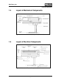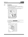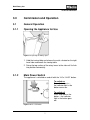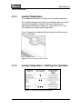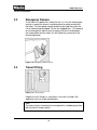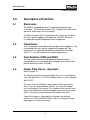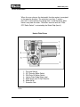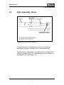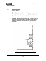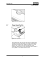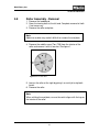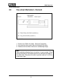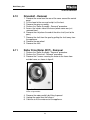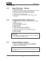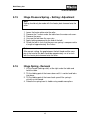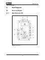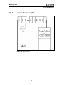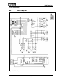
1
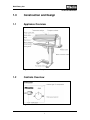
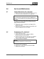
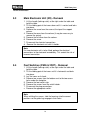
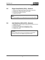
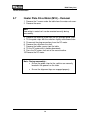
TECHNICAL INFORMATION B890 Rotary Iron © 2003 Miele B890 Rotary Iron - Table of Contents 1.0 CONSTRUCTION & DESIGN 1.1 Appliance Overview 1 1.2 Controls Overview 1 1.3 Technical Specifications 2 1.4 Layout of Mechanical Components 3 1.5 Layout of Electrical Components 3 2.0 INSTALLATION Installation Procedures 5 3.0 COMMISSION and OPERATION 3.1 General Operation 7 3.1.1 Opening the Appliance for Use 7 3.1.2 Main Power Switch 7 3.1.3 Ironing Temperature 8 3.1.4 Ironing Temperature / Clothing Care Symbols 8 3.1.5 Adjusting Roller Speed 9 3.1.6 Foot Pedal Operation 9 3.2 Emergency Release 10 3.3 Transit Fitting 10 4.0 DESCRIPTION of FUNCTION 4.1 Electronics 11 4.2 Transformer 11 4.3 Foot Switches 12 4.4 Heater Plate Drives – Operation 13 4.5 Roller Assembly / Drives 13 4.6 Heater Circuit 14 4.7 Finger Guard Switch 15 5.0 SERVICE and MAINTENANCE 5.1 Control Electronic – Removal 17 5.2 Transformer – Removal 17 5.3 Main Electronic Unit – Removal 18 5.4 Foot Switches – Removal 18 5.5 Finger Guard Switch – Removal 19 5.6 Limit Switches – Removal 19 5.7 Heater Plate Drive Motor - Removal 20 5.8 Roller Assembly - Removal 21 5.9 Free Wheel Mechanism - Removal 22 5.10 Drive Shaft – Removal 23 5.11 Roller Drive Motor - Removal 23 5.12 Heater Plate Cover - Opening 24 5.13 Leaf Spring With Holder – Replacement 24 5.14 Insulation Matting - Removal 24 5.15 Hinge Pressure Spring – Setting / Adjustment 25 5.16 Hinge Spring – Removal 25 5.17 Bowden Cable – Releasing Tension 26 5.18 Bowden Cable - Removal 26 6.0 FAULT DIAGNOSIS 6.1 Electronic Boards 28 6.1.1Main Electronic 28 6.1.2 Control Electronic 29 6.2 Wire Diagram 30 B890 Rotary Iron – List of Figures 1-1 Overview of Rotary Iron 1 1-2 Overview of Controls 1 1-3 Overview of Mechanical Components 3 1-4 Overview of Electrical Components 3 2-1 Removing the Feed Board 5 2-2 Removing the Protective Cover from the Roller 5 3-1 Opening the Rotary Iron 7 3-2 On / Off Switch 7 3-3 Temperature Adjustment Control 8 3-4 Roller Speed Control 9 3-5 Foot Pedal Operation 9 3-6 Emergency Release Latch 10 3-7 Transit Fitting 10 4-1 Heater Plate Drives 12 4-2 Roller and Drive Components 13 4-3 Heater Circuit 14 4-4 Heater Temperature Control 15 4-5 Finger Guard 15 5-1 End of Roller 21 5-2 Free Wheel Mechanism 22 5-3 Motor Mounting Bolts 23 6-1 Main Electronic 28 6-2 Control Electronic 29 6-3 Wiring Diagram 30 B890 Rotary Iron – List of Tables 1-1 Product Specifications 2 3-1 Temperature Clothing Care Symbols 8 6-3 Wiring Diagram 30 B890 Rotary Iron Technical Information 1.0 Construction and Design 1.1 Appliance Overview Figure 1-1: Overview of Rotary Iron 1.2 Controls Overview Figure 1-2: Overview of Controls 1 B890 Rotary Iron Technical Information 1.3 Technical Specifications Height Width Depth Weight 37” (41 ¾” folded) 39 3/8” (16 3/8 folded) 16 3/8” 84 lbs. Table 1-1: Product Specifications The appliance is supplied with a power cord and NEMA 6-20 P plug ready for connection to an AC single phase 208 V 60 Hz supply. The fuse rating is 20 amps. The actual amperage draw from the appliance is 13 amps. All electrical work should be carried out by a qualified electrician in accordance with local and national safety regulations. Do not connect the rotary ironer to an extension cord. Extension cords do not guarantee the required safety of the appliance (e.g. danger of overheating). Important If it is necessary to change the plug or power cord of the rotary iron, please take note of the following color codes of the wires: Green/yellow = ground Blue = live 1 Brown = live 2 WARNING: This appliance must be grounded 2 B890 Rotary Iron Technical Information 1.4 Layout of Mechanical Components Figure 1-3: Overview of Mechanical Components (B890 shown) 1.5 Layout of Electrical Components Figure 1-4: Overview of Electrical Components (B890 shown) 3 B890 Rotary Iron Technical Information 4 B890 Rotary Iron Technical Information 2.0 Installation 1. Unpack / uncrate the appliance from the box. 2. Remove the Transit Fitting - see supplementary information for details. 3. Move the appliance to the desired location - see supplementary information for details on moving the appliance. 4. Install recommended plug to the power cord - DO NOT plug in at this time. 5. Unlatch; remove the Feed Board from the appliance - see figure 1. Figure 2-1: First remove the feed board by lifting it out of the right hand holder, then pull it out to the left of the roller. 6. 7. 8. 9. Plug the appliance in; briefly turn on the power - the Heater Plate should rise. Turn off the power. Remove the protective cover from the roller - see figure 2. Perform an operational check; ensure all safety features and functions are in working order. Figure 2-2: Removing the protective cover from the roller. 5 B890 Rotary Iron Technical Information 6 B890 Rotary Iron Technical Information 3.0 Commission and Operation 3.1 General Operation 3.1.1 Opening the Appliance for Use Figure 3-1: Opening the Rotary Open 1. Hold the ironing table and release the catch situated on the right hand side underneath the ironing table. 2. Swing the top section of the rotary ironer to the side until it clicks into position horizontally. 3.1.2 Main Power Switch The appliance is switched on and off with the “I=On / 0=Off” button. To switch on Press the button in – the indicator light in the button comes on. To switch off Press and release the button – the indicator light in the button goes out. Figure 3-2: On / Off Switch 7 B890 Rotary Iron Technical Information 3.1.3 Ironing Temperature The temperature selector is used to set the ironing temperature. The individual temperature ranges are marked by dots on the dial around the temperature selector. These correspond to the international clothing care symbols for ironing (see 3.1.3). Turn the temperature selector to the temperature. The o C temperature indicator light will come on while the heater plate is heating up. Figure 3-3: Temperature Adjustment Control 3.1.4 Ironing Temperature / Clothing Care Symbols Table 3-1: Temperature Clothing Care Symbol 8 B890 Rotary Iron Technical Information 3.1.5 Adjusting the Roller Speed There are 5 roller speed settings, from low (approx. 2 meters per minute) to high (approx. 4.5 meters per minute). Turn the knob clockwise to increase the speed. A lower roller speed makes it easier to iron complicated articles such as shirts and blouses. It is also best to select a lower roller speed when ironing folded items, which may require more than one pass through the ironer to get them smooth and dry. Figure 3-4: Roller Speed Control 3.1.6 Foot Pedal Operation The ironing process is controlled by the foot pedal which has three operating positions: raising the heater plate (rest) pressing ironing Figure 3-5: Foot Pedal Operation 9 B890 Rotary Iron Technical Information 3.2 Emergency Release In the event of a power loss when the iron is in use the heater plate may be in a position where it could continue to make contact with the roller. The item being ironed would then be held there with the risk of it becoming damaged. To free the trapped item - Pull upward on the emergency release lever to reduce the pressure between the heater plate and the roller; this will allow easy removal of the item being ironed. Figure 3-6: Emergency Release Latch 3.3 Transit Fitting Figure 3-7: Transit Fitting Keep the transit fitting in a safe place. It must be re-fitted if the appliance ever has to be moved again. Note The rotary ironer should only be transported in a folded up position with the transit fitting in place. 10 B890 Rotary Iron Technical Information 4.0 Description of Function 4.1 Electronics The B890 is equipped with two (2) separate electronic board assemblies. The Control Electronic (A1) is fitted to the inside of the top cover, and houses the user controls. The Main Electronic (N2) is located beneath a cover on the top of the main vertical support of the appliance. The Main Electronic Is responsible for providing power to the components. 4.2 4.3 4.4 Transformer The Transformer is mounted to the base-plate of the appliance, and is covered by the main vertical support of the appliance. The Transformer is responsible for reducing voltage from 240 (208) VAC to 17 V for the electronic and several components. Foot Switches (2S26 and 2S27) The foot switches are mounted below the footplate and are actuated by the user to engage the heaterplate to the roller and to provide drive to the roller assembly. Heater Plate Drives - Operation Refer to figure 4-1. The Heater Plate drives are actuated by the user via the footplate (see Foot Switches 4.3). The Drive Motor (item 6) is then energized with 24VDC. The shaft of the Drive Motor is connected to the Eccentric Cam (item 7) via an e-clip connection (item 5) so as the Drive Motor turns the Eccentric Cam rotates. The rotation of the eccentric cam moves the Guide Strips (item4) and applies pressure to the spring (item 1) causing the heater plate to close against the roller. Power to the motor is interrupted as the guide strip actuator contacts the “Plate ON Roller Switch” (item 2), leaving the heater plate against the roller for ironing. 11 B890 Rotary Iron Technical Information When the user releases the foot pedal, the drive motor is energized in the opposite direction. The eccentric cam (item 7) rotates – pressure is released from the spring (item 1) and the heater plate moves away from the roller. The drives continue until the “Plate OFF Roller Switch” is actuated by the Guide Strip (item 4). Heater Plate Drives 6 7 1. 2. 3. 4. 5. 6. 7. Pressure Spring S27 Plate on Roller Switch S26 Plate Off Roller Switch Heater Plate Guide Strips (two) Motor Shaft and “E-Clip” Retainer Motor (M18) Eccentric Cam Figure 4-1: Heater Plate Drives 12 B890 Rotary Iron Technical Information 4.5 Roller Assembly / Drives Figure 4-2: Roller and drive components A single driveshaft is connected to the roller via a free-wheel bearing which permits the roller to turn in one direction only. The driveshaft is mechanically connected to the Drive Motor (M17). Power to the motor (24 VDC) is controlled by the users actions via the footplate (see Footswitches 4.3). 13 B890 Rotary Iron Technical Information 4.6 Heater Circuit Refer to figure 4-3. The Heaterplate contains three heating elements within a parallel Circuit (1 Kw / 52 ohms for each element). The temperature is regulated using an Adjustable Temperature Control Device (see figure 4-4) mounted in series before the heating elements. In addition, the heating circuit contains two Thermal (Hi-limit) Cutouts also electrically mounted in series to the heating elements. Should the temperature exceed 2000 C the circuit electrically interrupted. Figure 4-3: Heater electrical circuit 14 B890 Rotary Iron Technical Information Figure 4-4: Heater temperature control 4.7 Finger Guard Switch Figure 4-5: Finger Guard The Finger Guard is the small lip in the front of the Heater Plate Assembly, that can be lifted slightly. The Finger Guard Switch is actuated if the Finger Guard is lifted or moved from it’s regular position. This system ensures that if the operator should accidentally make contact with the Heaterplate while the Roller is turning; power is interrupted to prevent injuries. 15 B890 Rotary Iron Technical Information 16 B890 Rotary Iron Technical Information 5.0 5.1 Service and Maintenance Control Electronic (A1) - Removal 1. Remove the cover screw and lift off the cover (rear first). 2. Tilt cover forward and upward from the appliance. Note Use caution when removing cover from the appliance as wiring is still connected to the control board mounted inside the cover. To Remove the Control Panel Circuit Board from the cover continue as follows: 3. Remove the screws securing the circuit board to the inside of the cover. 4. Make note of the location of electrical connections and carefully unplug from the circuit board. 5.2 Transformer (T1) - Removal 1. Lay the ironer on its back. 2. Remove the tension from the Bowden cable by disconnecting the tensioner spring. 3. Remove four bolts from the underside of the footplate from the support column using a socket spanner. 4. Carefully remove the footplate. Caution The electrical connections are not very long. 5. Disconnect the 2 group plugs. 6. Remove the 2 screws from the transformer holder. 7. Remove the transformer. 17 B890 Rotary Iron Technical Information 5.3 Main Electronic Unit (N2) - Removal 1. Lift the handle (locking catch) at the right under the table and hold the table. 2. Tilt the folding part of the ironer down until it is vertical and locks into place. 3. Remove the screw from the cover at the top of the support column. 4. Remove the cover from the column (it may be necessary to remove the spring). 5. Remove the left cover from the column. 6. Remove the screw. 7. Disconnect the electrical connections. 8. Remove the electronic unit with its holder. Note If a new electronic unit is to be fitted, perform the electrical connections to the electronic immediately. This avoids the risk of incorrect connection. 5.4 Foot Switches (2S26 & 2S27) - Removal 1. Lift the handle (locking catch) at the right under the table and hold the table. 2. Tilt the folding part of the ironer until it is horizontal and locks into place. 3. Lay the ironer on its back. 4. Remove two screws from the bottom next to the two access holes under the footplate. 5. Remove the foot switch strip. 6. Remove the screws from the switch holder. 7. Disconnect the plug connections. 8. Remove the appropriate switch. Note When refitting the screws, slide the bearings into the correct positions so the guide lugs engage in their holes. 18 B890 Rotary Iron Technical Information 5.5 Finger Guard Switch (F6/5) - Removal 1. 2. 3. 4. Perform the “Opening the Heater Plate Cover” procedure. Remove the 2 screws from the switch holder. Disconnect the plug connections. Remove the switch. Note The switching point of the finger guard strip cannot be modified. 5.6 Limit Switches (S26 & S27) - Removal 1. 2. 3. 4. 5. Remove the 2 screws under the table from the motor unit cover. Remove the cover. Disconnect the plug from the appropriate switch. Remove the 2 screws from the appropriate switch. Remove the switch. Caution When refitting, take care to ensure the plugs are connected correctly as they are not coded or keyed connections. 19 B890 Rotary Iron Technical Information 5.7 Heater Plate Drive Motor (M18) – Removal 1. Remove the 2 screws under the table from the motor unit cover. 2. Remove the cover. Note How wiring is routed so it can be rerouted correctly during reassembly. 3. Remove the retaining screw from the left and right guide strips. 4. Tilt the guide strips with the switches slightly and remove them. 5. Disconnect the plug connections from the DC motor. 6. Remove the e-clip from the shaft. 7. Remove the holder screws from the table. 8. Tilt the DC motor with its holder downwards. 9. Press the DC motor shaft out of the eccentric drive. 10. Remove the DC motor. Note - During reassembly… Ensure the guide strips for the switches are correctly located in the grooves on the slider Ensure the alignment lugs are engaged properly 20 B890 Rotary Iron Technical Information 5.8 Roller Assembly - Removal 1. Remove the feed board. 2. Open the ironing cloth at the left end. Complete removal of cloth is not necessary. 3. Remove the roller end plate. Note Adhesive residue may make it difficult to remove the end plate. 4. Remove the middle screw (Torx T30) from the interior of the roller and remove it with its washer. See figure 1. Figure 5-1: End of roller 5. Loosen the roller at the right by giving it an axial jolt using both hands. 6. Remove the roller. Note When refitting the end plate, ensure the notch aligns with the lug on the interior of the roller. 21 B890 Rotary Iron Technical Information 5.9 Free-wheel Mechanism - Removal Figure 5-2: Free-wheel mechanism 1. Perform the “Roller Assembly - Removal” procedure. 2. Unscrew the three screws from the interior of the roller. 3. Remove the free-wheel mechanism and bearing flange. Note Reassemble by following these instructions in reverse order. When refitting, position the free-wheel mechanism and bearing flange on the roller shaft. Then place the roller in position and turn it until the screw holes align. 22 B890 Rotary Iron Technical Information 5.10 5.11 Driveshaft - Removal 1. Remove the screw from the rear of the cover around the control panel. 2. Lift the hood at the rear and unclip it at the front. 3. Remove the cover assembly. 4. Perform the “Roller Assembly - Removal” procedure. 5. Access the interior side of the frame (where cover was just removed from). 6. Remove the e-clip from the end of the drive shaft (next to the gear) 7. Remove the shaft from the gear by pulling the shaft away from the appliance. 8. Remove the cog wheel. 9. Remove the shaft. Roller Drive Motor (M17) - Removal 1. Perform the “Roller Assembly - Removal” procedure. 2. Perform the “Driveshaft - Removal” procedure. 3. Remove the 2 screws securing the motor to the frame from outside frame, as shown in figure2. Figure 5-3: The motor is mounted to the frame using two bolts. 4. Remove the motor partially by lifting it upward. 5. Unplug the motor from the harness. 6. Continue to lift the motor out of the appliance. 23 B890 Rotary Iron Technical Information 5.12 5.13 Heater Plate Cover – Opening 1. 2. 3. 4. 5. 6. Switch on the machine. Operate the foot switch to lower the heater plate onto the roller. Switch off the machine and unplug it from the mains. Remove the screws from the left and right end-caps. Remove the left and right end caps. Lift the cover at the top and carefully slide it down onto the folding part. Leaf Spring With Holder - Replacement 1. Perform the “Opening The Heater Plate Cover” and “Insulation Matting. 2. Removal” procedures. 3. Pull the tensioning strap upwards. 4. Remove the circlip. 5. Remove the bolt. 6. Remove the wiring harness fixing clips. 7. Disconnect the earth wire from the bracket. 8. Remove the holder fixing screws from the heater plate. 9. Remove the holder. 10. Fit the new holder. Service Tip If the Emergency Release does not allow laundry to be removed the leaf spring may need replacement. 5.14 Insulation Matting - Removal 1. Perform the “Opening the Heater Plate Cover” procedure. 2. Disconnect the electrical connections from the switches. 3. Remove the insulation matting. Note Take care not to damage the matting cutouts when pulling it free of the switches. 24 B890 Rotary Iron Technical Information 5.15 Hinge Pressure Spring – Setting / Adjustment Note Setting should only be made with the heater plate lowered onto the roller. 1. 2. 3. 4. 5. 6. Lower the heater plate onto the roller. Remove the 2 screws under the table from the motor unit cover. Remove the cover. Unscrew the bolt from the cross pin. Apply locking compound to the end of the bolt. Screw the bolt in such that the pressure spring is compressed to a length of approximately 13/16 inches Note After correct setting, the gap between the bolt head and the cross pin at the head of the bolt should be approximately 1/16 of an inch with the heater plate lowered onto the roller. 5.16 Hinge Spring - Removal 1. Lift the handle (locking catch) at the right under the table and hold the table. 2. Tilt the folding part of the ironer down until it is vertical and locks into place. 3. Tilt the folding part of the ironer back up until the spring is virtually un-tensioned. 4. Release the spring from its holder using needle-nose pliers. 25 B890 Rotary Iron Technical Information 5.17 Bowden Cable - Releasing Tension 1. Access the underside of the iron directly under the main vertical support. 2. Use a suitable tool to grasp the hook end of the spring. 3. Carefully lift the spring from its mounting hole. 4. Move spring away from the mounting hole and allow spring to pull itself into the spring opening. Caution When spring tension has been removed from the Bowden Cable the iron will open very differently and have no self tensioning at the hinge. 5.18 Bowden Cable - Removal 1. Perform “Bowden Cable - Releasing Tension” (5.17). 2. Carefully open the iron into the vertical position. 3. Loosen the cable retainer screw and move the cable retainer to the side. 4. Pull cable from retainer area and lift cable from vertical support. It may be necessary to reposition the iron if the hook on the spring attached itself to the frame again. 26 B890 Rotary Iron Technical Information 27 B890 Rotary Iron Technical Information 6. Fault Diagnosis 6.1 Electronic Boards 6.1.1 Main Electronic (N2) Figure 6-1: Main Electronic 28 B890 Rotary Iron Technical Information 6.1.2 Control Electronic (A1) Figure 6-2: Control Electronic 29 B890 Rotary Iron Technical Information 6.2 Wire Diagram Figure 6-3: Wire Diagram 30 B890 Rotary Iron Technical Information 31