1
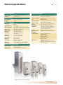
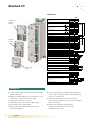
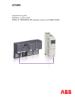
Catalog
ABB industrial drives
ACS850, drive modules, 1 to 600 Hp /
1.1 to 500 kW
Contents
Type code stucture:
1
2
3
4
5
2
Product series
- Type & dimension
- Ratings
- Voltage
Options
Control
Highlights
Contact
ACS850
-
04
-
XX
-
5
+
XX
ABB industrial drives, ACS850, drive modules, 1 to 600 Hp
ABB industrial drives........................................................4
Drive modules main features............................................5
Technical specifications...................................................7
Types, ratings and dimensions.........................................8
Brake Options.................................................................9
Other Options................................................................11
Standard I/O..................................................................14
EMC filters.....................................................................15
Programming.................................................................16
Software features..........................................................17
PC tools........................................................................18
Remote monitoring and diagnostic tools........................19
Summary of features and options..................................20
Contact and web information.........................................21
1
2
3
4
5
3
ABB industrial drives
ACS850
-
04
-
XX
-
5
ABB industrial drives
XX
ACS850-04 single drive modules
ABB industrial drives are highly flexible AC drives, designed
for industrial applications, specifically for those in process
industries such as the pulp & paper, metals, mining, cement,
power, chemical, and oil &
gas industries.
ACS850-04 modules are UL listed in compliance with
UL508C-2003. They offer a wide range of internal options
such as extended I/O and high speed communications. In
addition to these, a wide selection of external accessories is
also available.
The drives can be configured to meet the precise needs of
these industries, and hence order-based configuration is an
integral part of the offering. Covering a wide power and
voltage range and with a vast array of standard and optional
features, the drives are readily programmable, making their
adaptation to different applications easy.
Because the modules are specifically designed for cabinet
assembly, they can be mounted side-by-side. Cabinet
assembly documentation is included. The documentation
gives examples of different cabinet configurations,
examples of drawings and hints on the selection of auxiliary
equipment. The flexibility and programmability of the
modules makes them an ideal choice for many applications in
a variety of industries.
Robust design
The current ratings of ABB industrial drives are designed for
applications that have a high overload requirement.
At the heart of the drive is the motor control platform,
Direct Torque Control (DTC) that provides accurate static
and dynamic speed and torque control, high starting torque
and long motor cables.
Furthermore, built-in drive options make the drive installation
fast and easy.
The drive is designed for a long working life and as such,
parts like fans and capacitors have been selected to maximize
their lifetime. This, together with the extensive protection
features and design details, such as coated circuit boards,
results in excellent reliability for the demanding industrial
market.
Drive modules
Drive modules are designed to be built into a customer’s
own cabinet. The ACS850-04 units are complete single drive
modules that are optimized for this purpose, using minimal
cabinet space while ensuring cabinet assembly is as easy as
possible.
ABB industrial drive modules are suitable for system
integrators and/or OEMs which are making their own
systems. The modules typically have an IP20 enclosure class.
4
+
1
Product series
Type code
The type code is a unique reference number that clearly
identifies the drive by construction, power, voltage rating
and selected options. Using the type code you can specify
your drives from the wide range of available selections.
Customer-specific options are added to the type code using
the corresponding + code.
Safe Torque Off
The Safe Torque Off (STO) function disables the control
voltage of the power semiconductors in the drive output
stage, thus preventing the inverter from generating the
voltage required to rotate the motor.
With this function, the power supply does not need to be
turned off while doing cleaning or maintenance on the nonelectrical parts of the machinery.
The function meets the requirements of these safety
standards:
Safety Integrity Level 3 (SIL 3) according to IEC 61508
Safety Category 3 acc. to EN 954-1
Drive modules main features
Features
Advantage
Benefits
Compact size
Smallest frame size is only 3-1/2 inches wide.
More drives can be placed in the same cabinet.
Optimum installation layout and efficient cabinet
space usage.
Space and cost savings in the cabinets and
electrical rooms.
Side by side mounting
Minimized cabinet wall space.
No need to remember correct air gaps.
Space and cost savings in the cabinets and
electrical rooms.
Modular design
Many standard features and a wide range of options
allow different system configurations.
Fits many application needs.
Offers flexibility in system design.
Optimal location of power
terminals
Top-down power flow in frames A to D enables the
most optimal cabinet layout in many cases.
Easy connection of power cables.
Optimum installation layout and efficient cabinet
space usage.
Optimized design from an EMC point of view.
Integrated braking chopper
Braking chopper as standard up to 60 Hp (frames
A to D) and a built-in option for other frame sizes.
Compact and cost-effective design.
Intuitive human-machine
interface
Large alphanumeric display showing different
assistants and macros.
Extremely easy to use and commission the drive.
DriveStudio PC-program offers easy access to drive
parameter setting and start-up features.
Faster and more accurate drive configuration.
Optimal drive settings as assistants offer
interactive help.
Drive programming and
configuration
Can replace relays and small PLCs with function block
programming.
Lower investment cost.
Higher flexibility in system design.
Memory unit for easy drive
management
Complete drive configuration and settings are stored
in a separate memory unit.
Power or control unit can be replaced without
parameter setting.
Drive functionality can be easily configured,
modified or updated with the memory unit.
Offers quick and easy after-sales service.
Robust main circuit design
Enhanced reliability.
Coated boards and long life time components.
Cooling supervision (depending on frame size).
Less process interruptions.
Lower maintenance costs.
Extensive protection
Advanced thermal protection of the drive
semiconductors and motor.
Several adjustable protections for the drive and
adjoining equipment ensure a reliable operation.
Higher process uptime.
Early warning of any production interruptions.
Maintenance assistant
Indicates preventive maintenance needs of drive,
motor or machine.
User-set alarms and triggering limits.
Monitors running hours, cooling fan running hours,
number of relay switchings etc.
Helps with maintenance schedules and cost control
of maintenance.
Fewer unexpected process interruptions.
Diagnostic assistant
Drive helps in locating failures or reasons for
performance changes and suggest remedies.
Reduced process downtime.
Faster recovery to drive's optimum performance.
Energy saving calculator
Monitors used and saved energy by the motor in kWh,
Euros and $.
Easy check of the return on investment.
Load analyzer
Shows the load profile of the drive.
Easy process analysis.
Energy optimizer
Maximizes efficiency by optimizing the motor flux.
Improves motors performance therefore makes
process more efficient.
Energy savings are realised and money saved.
Modular and compact design
User interface and programming
Designed for reliability
Optimized use
Product series
1
5
Drive modules main features
Features
Advantage
Benefits
Standard induction
(asynchronous) and permanent
magnet motors compatibility
Same drive can be used to control different
motor types.
Savings in investment costs.
Savings in spares stockholding.
Wide range of speed feedback
interfaces
In the rare case a speed feedback device is needed,
almost any type of device can be connnected.
Additional hardware flexibility.
Unmatched open-loop performance.
Embedded Modbus link or
drive-to-drive link is standard
No additional hardware needed for master-follower
communication or Modbus.
Galvanic isolation.
Lower investment cost.
More reliable, disturbance-free isolation.
Different communication
options
Flexibility with master communication - drive supports
PROFIBUS, CANopen, DeviceNet, Modbus, Modbus
TCP and Ethernet / IP communication.
Drive can be applied to many existing processes.
Integrated Safe Torque-Off
function (SIL 3)
Safe Torque-Off is used to prevent unexpected
start-up.
High SIL class means high reliability of the
safety function.
Can also be used to implement Emergency Stop
without contactors.
Enhances safety of the machines.
Cost-effective and certified solution for safe
machine maintenance.
Satisfies new safety directives IEB 61508, IEC
62061 and EN ISO 13489-1.
Extensive configurable
standard I/Os.
Optimized accessibility.
No need for extra I/O.
Lower cost.
Fewer parts and installation work needed for
cabinet assembly.
Optional I/O extensions
Plug-in analog and digital I/O extensions.
Extends drives’ scope, performance and
applications opportunities.
Direct Torque Control
Accurate, dynamic and static speed and torque control.
Excellent process control even without pulse encoder.
Power interruption ride-through using kinetic energy
of load.
Fast reaction to load or voltage variations.
No shock torques.
No torque ripple - minimized risk for torsional vibration.
Less noise during motor operation.
Output frequency up to 500 Hz.
Enhanced motor identification at stand still.
Improves product quality, productivity and reliability
Lower investment cost.
No unnecessary trips or process interruptions
Lower mechanical stress.
Suitable for use where audible noise is an issue.
Applicable in high speed applications.
Better process control due to more accurate
identification.
Can do motor identification without decoupling
the load.
High overload and high starting
torque
Smooth start without over-dimensioning the drive.
Longer motor and gear lifetime thereby reduced
maintenance costs.
Global market leader in
AC drives
Long experience
Well proven, safe and reliable solutions.
Application know-how.
Highly reliable drives.
World wide service and support
network
Professional support available around the world.
High quality service and support wherever
you need it.
Control and performance
Made by ABB
Note: some of the features will be available during 2009
6
1
Product series
Technical specifications
Mains connection
Supply voltage
Frequency
Operating conditions
3-phase 380 to 500 V +10 /- 15%
50 to 60 Hz ± 5%
Ambient temperature
DC connection
DC voltage level
Charging
485 to 675 V DC ± 10%
Internal
Motor connection
Motor types
Output frequency
Motor cable length
Motor control
Torque control:
Open loop
Closed loop
Open loop
Closed loop
Speed control:
Open loop
Closed loop
Open loop
Closed loop
Degree of protection
Induction motors and permanent magnet
motors
0 to 500 Hz
A&B frames 150 m (with 2nd env. Filter 100 m)
C-G frames: 300 m (with 2nd env. Filter 100 m)
ABB´s Direct Torque Control
Torque step rise time:
<5ms with nominal torque
<5ms with nominal torque
Non-linearity:
±4% with nominal torque
±3% with nominal torque
Static accuracy:
10% of motor slip
0.01% of nominal speed
Dynamic accuracy
0.3 to 0.4%sec. with 100% torque step
0.1 to 0.2%sec. with 100% torque step
Installation altitude
Relative humidity
Climatic/
environmental
conditions
Vibration
EMC (According to
EN 61800-3)
Functional safety
Compliance
IP20 as per EN 60529 (G frame IP00);
Open type as per UL 508.
-10 to +55 °C (G frame +50 °C), derating
above 40 °C
No frost allowed
0 to 4000 m (IT network: 2000 m), derating
above 1000 m: 1% / 100 m
max. 95%, no condensation allowed
Class 3K3, 3C2 acc. to EN 60721-3-3.
Oil mist, formation of ice, moisture
condensation, water drops, water spray,
water splashes and water jets are not
permissible (EN 60204, Part 1)
Class 3M4 as per EN 60721-3-3
Categories C2 and C3 with optional filter
(STO acc. EN 61800-5-2)
IEC 61508: SIL 3
EN 954-1: Category 4
IEC 62061: SILCL 3
EN ISO 13849-1: PL e
Certified by TÜV
Frames A - D: CE, GOST R, UL, cUL;
pending: CSA, C-Tick
Frames E0 - G: CE, GOST R; pending: UL,
cUL, CSA, C-Tick
Braking power connection
Braking chopper
Braking resistor
Standard in frames A to D, built-in option in
the other frame sizes
External resistor connected to drive
Shown with optional control panel (+J400)
Product series
1
7
Types, ratings and dimensions
Feature / frame size
Current & Power
Nominal current (400 V)
Maximum current (400 V)
Typical motor power (400 V)
Braking chopper
Braking resistor
Input choke
EMC filter / C3 *
EMC filter / C2
Mounting and cooling
Air cooling
Side-by-side mounting
DIN-rail mounting
Removable power connectors
Removable control connectors
= standard
A
B
C
D
E0
E
G
3 to 8 A
4.4 to 10.5 A
1.1 to 3 kW
10.5 to 18 A
13.5 to 21 A
4 to 7.5 kW
25 to 50 A
33 to 66 A
9 to 22 kW
61 to 94 A
78 to 124 A
30 to 45 kW
103 to 144 A
131 to 170 A
55 to 75 kW
166 to 210 A
202 to 348 A
90 to 160 kW
430 to 720 A
588 to 1017 A
200 to 400 kW
–
–
–
= option, internal
= option, external
– = not available
–
–
–
–
–
–
–
–
–
* External EMC filters are plug-in type filters that fit to the drive within its installation footprint.
Ratings (UN = 480V)
Type Code
ACS850-04--03A0-5
ACS850-04--03A6-5
ACS850-04--04A8-5
ACS850-04--06A0-5
ACS850-04--08A0-5
ACS850-04--010A-5
ACS850-04--014A-5
ACS850-04--018A-5
ACS850-04--025A-5
ACS850-04--030A-5
ACS850-04--035A-5
ACS850-04--044A-5
ACS850-04--050A-5
ACS850-04--061A-5
ACS850-04--078A-5
ACS850-04--094A-5
ACS850-04-103A-5
ACS850-04-144A-5
ACS850-04-166A-5
ACS850-04-202A-5
ACS850-04-225A-5
ACS850-04-260A-5
ACS850-04-290A-5
ACS850-04--430A-5
ACS850-04--521A-5
ACS850-04--602A-5
ACS850-04--693A-5
ACS850-04--720A-5
Frame
Size
A
A
A
A
A
B
B
B
C
C
C
C
C
D
D
D
E0
E0
E
E
E
E
E
G
G
G
G
G
Input RMS Current
Nominal Ratings
Light Duty
Heavy Duty
I1N
*I1N
continuous
current
I2N
rated
power
P2N
maximum
current
IMAX
continuous
current
ILD
rated
power
PLD
continuous
current
IHD
rated
power
PHD
A
2.3
3.1
4
5.5
6.6
8.7
12
16
20
26
30
36
42
55
65
82
100
142
163
198
221
254
283
423
501
581
674
705
A
4
6
7
9
11
13
18
23
–
–
–
–
–
–
–
–
–
–
–
–
–
–
–
–
–
–
–
–
A
3
3.6
4.8
6
8
10.5
14
18
25
30
35
44
50
61
78
94
103
144
166
202
225
260
290
430
521
602
693
720
HP
1.5
2
3
3
5
5
7.5
10
15
20
25
30
30
40
60
60
75
100
125
150
150
200
200
350
450
500
550
600
A
4.4
5.3
7
8.8
10.5
13.5
16.5
21
33
36
44
53
66
78
100
124
138
170
202
282
326
326
348
588
588
840
1017
1017
Adc
2.8
3.4
4.5
5.5
7.6
9.7
13
16.8
23
28
32
41
46
57
74
90
100
141
155
184
220
254
286
425
516
590
679
704
HP
1
2
2
3
5
5
7.5
10
15
20
20
30
30
40
50
60
75
100
125
150
150
200
200
350
450
500
550
600
Adc
2.5
3
4
5
6
9
11
14
19
24
29
35
44
52
69
75
88
100
115
141
163
215
232
340
370
477
590 1)
635 2)
HP
1
1.5
2
3
3
5
7.5
10
10
15
20
25
30
40
50
50
60
75
75
100
125
150
150
250
300
400
500
500
Noise
level
Air
Flow
@ 60 Hz
dBA
47
47
47
47
47
39
39
39
63
63
71
71
71
70
70
70
65
65
65
65
65
65
65
72
72
72
72
72
ft3/min
10
10
10
10
10
30
30
30
80
80
120
120
120
170
170
170
100
240
240
240
240
240
240
720
720
720
720
720
1) For ambient temperature of less than 95 deg. F (35 C), maximum overload is 150% of IHD. For ambient temperature of 104 deg. F (40 C), maximum overload is 145% of IHD.
2) For ambient temperature of less than 86 deg. F (30 C), maximum overload is 150% of IHD. For ambient temperature of 104 deg. F (40 C), maximum overload is 140% of IHD.
Dimensions
Nominal ratings:
I2N: rated current available continuously without overloading at 40 °C.
Imax: maximum output current. Available for 10 s at start, otherwise as long as
allowed by drive temperature. Note: max. motor shaft power is 150% Phd.
Typical ratings:
No-overload use
PN: typical motor power in no-overload use.
Light-duty use
ILd: continuous current allowing 110% ILd for 1min / 5 min at 40 °C.
PLd: typical motor power in light-duty use.
Heavy-duty use
Ihd: continuous current allowing 150% Ihd for 1min / 5 min at 40 °C.
Phd: typical motor power in heavy-duty use.
The current ratings are the same regardless of the supply voltage within one
voltage range.
The ratings apply at 40 °C ambient temperature.
8
1
Product series
Frame
size
A
B
C
D
E0
E
G6
Height 3)
in
14.3
15.0
22.3
22.3
23.7
27.6
61.6
mm
364
380
567
567
602
700
1564
Depth 4)
in
7.8
10.8
10.9
10.9
13.9
17.4
22.4
mm
197
274
276
276
354
443
568
Width
in
3.7
4.0
6.5
8.7
10.9
12.3
22.1
mm
93
101
166
221
276
312
562
Weight
lb
7
11
35
51
77
147
441
kg
3
5
16
23
35
67
205
Notes
All dimensions and weights are without options.
3) Height is the maximum measure without clamping plates.
4) An additional 50 mm should be reserved for feedback cabling if
FEN-01, 11 or 21 option is used.
5) Control panel adds 0.9in (23mm) to the depth
6) Frame G drives include separately mounted control section, 12.8h x 4.5d x 3.7w, 3 lb.
Brake options
Brake resistor
Brake chopper
The ACS850 has built in brake choppers for all types. Therefore, no additional space or installation time is needed. The
brake chopper is part of the standard delivery for the frame
sizes A-D. For the other frames a brake chopper is a selectable option.
Brake resistors are separately available for all ACS850 drives.
Resistors other than the standard resistors may be used providing the specified resistance value is not decreased, and the
heat dissipation capacity of the resistor is sufficient for the
drive application.
Braking control is integrated into the ACS850 through frame
G. It controls the braking, supervises the system status and
detects failures such as brake resistor and resistor cable short
circuits, chopper short circuit, and calculated resistor overtemperature.
For ACS850 units, no separate fuses in the brake circuit are
required if the following conditions are met:
n The ACS850 mains cable is protected with fuses
n No mains cable/fuse overrating takes place
Dynamic Braking Table - 380-480V applications, stopping duty only
Drive P/N
ACS850-04-
HP
ND
06A0-5
3
Duty Cycle = 3sec on / 27sec off
Resistor
Ohms Watts
Dimensions
Part No.
P14494-61
120
300
12Wx5Dx5H
Duty Cycle = 10sec on / 50sec off
Resistor
Ohms Watts
Dimensions
Part No.
P14494-61
120
300
12Wx5Dx5H
08A0-5
5
P14494-61
120
300
12Wx5Dx5H
ABB-48431-110
120
600
12Wx7Dx5H
10A0-5
5
ABB-48431-050
80
400
12Wx5Dx5H
ABB-48431-052
80
800
12Wx7Dx5H
014A-5
7.5
ABB-41152
45
600
12Wx7Dx5H
P14494-25
45
800
12Wx7Dx5H
018A-5
10
ABB-41152
45
600
12Wx7Dx5H
P14494-26
45
1260
12Wx10Dx5H
025A-5
15
ABB-48431-002
22
819
12Wx7Dx5H
ABB-48431-004
22
1408
12Wx13Dx5H
030A-5
20
ABB-41154
22
900
12Wx10Dx5H
ABB-48431-005
22
1862
12Wx16Dx5H
035A-5
20
ABB-48431-003
22
1140
12Wx10Dx5H
ABB-44472
22
1904
12Wx16Dx5H
044A-5
30
ABB-48431-030
13
1433
12Wx13Dx5H
ABB-48431-033
13
3328
19Wx10Dx5H
050A-5
30
ABB-48431-030
13
1433
12Wx13Dx5H
ABB-48431-033
13
3328
19Wx10Dx5H
061A-5
40
ABB-48431-031
13
1872
12Wx16Dx5H
ABB-48431-033
13
3328
19Wx10Dx5H
078A-5
50
ABB-48431-033
13
3328
19Wx10Dx5H
ABB-44495
13
4153
26.5Wx10Dx5H
094A-5
60
ABB-48431-033
13
3328
19Wx10Dx5H
ABB-48431-036
13
6292
26.5Wx13Dx5H
26.5Wx16Dx5H
103A-5
75
ABB-41170
8
4600
26.5Wx10Dx5H
ABB-48431-120
8
6272
144A-5
100
ABB-41161
6
4600
26.5Wx10Dx5H
ABB-44499
6.1
9444
28Wx10Dx10H
166A-5
125
ABB-48431-183
4.3
6209
26.5Wx13Dx5H
ABB-48431-184
4.3
10750
28Wx10Dx10H
202A-5
150
ABB-44479
4.26
9872
26.5Wx16Dx5H
ABB-44480
4.26
11696
28Wx10Dx10H
225A-5
150
ABB-44479
4.26
9872
26.5Wx16Dx5H
ABB-44480
4.26
11696
28Wx10Dx10H
260A-5
200
ABB-44479
4.26
9872
26.5Wx16Dx5H
ABB-48431-185
4.3
17067
28Wx13Dx10H
Drive P/N
ACS850-04-
HP
ND
06A0-5
3
08A0-5
5
ABB-48431-110
120
600
12Wx7Dx5H
P14494-18
150
1200
12Wx13Dx5H
10A0-5
5
ABB-48431-052
80
800
12Wx7Dx5H
ABB-48431-053
80
1600
12Wx13Dx5H
014A-5
8
P14494-26
45
1260
12Wx10Dx5H
P14494-27
45
1920
12Wx16Dx5H
018A-5
10
P14494-26
45
1260
12Wx10Dx5H
P14494-28
45
2450
19Wx13Dx5H
025A-5
15
ABB-48431-005
22
1862
12Wx16Dx5H
ABB-48431-008
22
3168
19Wx13Dx5H
Duty Cycle = 30sec on / 180sec off
Resistor
Ohms Watts
Dimensions
Part No.
ABB-48431-110
120
600
12Wx7Dx5H
Duty Cycle = 60sec on / 180sec off
Resistor
Ohms Watts
Dimensions
Part No.
P14494-17
150
900
12Wx10Dx5H
030A-5
20
ABB-48431-007
22
2426
19Wx10Dx5H
ABB-48431-009
22
5632
26.5Wx10Dx5H
035A-5
23
ABB-44515
22
2910
19Wx13Dx5H
ABB-48431-009
22
5632
26.5Wx10Dx5H
044A-5
30
ABB-44474
13
3558
19Wx10Dx5H
ABB-48431-036
13
6292
26.5Wx13Dx5H
050A-5
30
ABB-44474
13
3558
19Wx10Dx5H
ABB-48431-036
13
6292
26.5Wx13Dx5H
061A-5
40
ABB-44517
13.3
5093
26.5Wx13Dx5H
ABB-48431-037
13
8125
26.5Wx16Dx5H
078A-5
50
ABB-48431-036
13
6292
26.5Wx13Dx5H
ABB-48431-038
13
11700
28Wx13Dx10H
094A-5
60
ABB-48431-037
13
8125
26.5Wx16Dx5H
ABB-48431-038
13
11700
28Wx13Dx10H
28Wx16Dx10H
103A-5
75
ABB-48431-122
8
11552
28Wx10Dx10H
ABB-48431-123
8
15488
144A-5
100
ABB-44500
6.44
10892
28Wx10Dx10H
ABB-44544
6.39
21955
28Wx16Dx10H
166A-5
125
ABB-48431-185
4.3
17067
28Wx13Dx10H
ABB-48431-187
4.3
27520
30Wx18Dx24H
202A-5
150
ABB-48431-186
4.3
21070
28Wx16Dx10H
ABB-48431-188
4.3
34830
30Wx18Dx24H
225A-5
150
ABB-48431-186
4.3
21070
28Wx16Dx10H
ABB-48431-188
4.3
34830
30Wx18Dx24H
260A-5
200
ABB-48431-187
4.3
27520
30Wx18Dx24H
ABB-48431-189
4.3
43000
30Wx18Dx24H
Options
2
9
Brake options
Dynamic Braking Table - 380-480V applications, stopping duty only
Drive P/N
ACS850-04290A-5
HP
ND
200
Duty Cycle = 3sec on / 27sec off
Resistor
Ohms Watts
Dimensions
Part No.
ABB-48431-271
2.9
14210
28Wx10Dx10H
Duty Cycle = 10sec on / 50sec off
Resistor
Ohms Watts
Dimensions
Part No.
ABB-48431-272
2.9
16313
28Wx10Dx10H
300
ABB-48431-330
2.2
14080
28Wx16Dx10H
ABB-48431-332
2.2
26620
30Wx18Dx24H
430A-5
350
ABB-48431-331
2.2
17820
28Wx13Dx10H
ABB-48431-333
2.2
31680
30Wx18Dx24H
400
ABB-48431-392
1.7
17000
28Wx13Dx10H
ABB-48431-394
1.7
30983
30Wx18Dx32H
521A-5
450
ABB-48431-393
1.7
24480
30Wx18Dx16H
ABB-44508
1.72
43916
30Wx18Dx32H
602A-5
500
ABB-48431-450
1.35
24604
30Wx18Dx16H
ABB-48431-453
1.35
46204
30Wx18Dx32H
693A-5
550
ABB-48431-512
1
27225
30Wx18Dx24H
ABB-48431-516
1
50625
30Wx18Dx24H
720A-5
600
ABB-48431-512
1
27225
30Wx18Dx24H
ABB-48431-516
1
50625
30Wx18Dx24H
Drive P/N
ACS850-04-
HP
ND
290A-5
430A-5
521A-5
200
Duty Cycle = 30sec on / 180sec off
Resistor
Ohms Watts
Dimensions
Part No.
ABB-48431-273
2.9
23490
28Wx16Dx10H
Duty Cycle = 60sec on / 180sec off
Resistor
Ohms Watts
Dimensions
Part No.
ABB-48431-275
2.9
41760
30Wx18Dx32H
300
ABB-48431-334
2.2
40095
30Wx18Dx32H
ABB-43503
2.27
68450
30Wx18Dx48H
350
ABB-48431-334
2.2
40095
30Wx18Dx32H
ABB-43503
2.27
68450
30Wx18Dx48H
400
ABB-44508
1.72
43916
30Wx18Dx32H
ABB-43504
1.72
82280
30Wx18Dx40H
450
ABB-48431-396
1.7
58183
30Wx18Dx32H
ABB-43504
1.72
82280
30Wx18Dx40H
104527
30Wx18Dx72H
602A-5
500
ABB-48431-455
1.35
68344
30Wx18Dx32H
ABB-44553
1.38
693A-5
550
ABB-48431-517
1
67600
30Wx18Dx40H
ABB-48431-519
1
122500 (2) 30Wx18Dx40H
720A-5
600
ABB-48431-518
1
90000
30Wx18Dx48H
ABB-48431-519
1
122500 (2) 30Wx18Dx40H
* Requires two resistor assemblies each rated as show and connected in series. (Order quantity 2)
10
2
Options
Options
Optional Inputs and Outputs
Fieldbus control
The ACS850 drive modules have one of the most extensive
offering of standard Inputs and Outputs (I/O) in the market.
In addition, optional I/O extension modules are available,
providing additional connection possibilities. Options include
analog and digital extension modules and pulse encoder
interface modules which are mounted in the slots on the
ACS850 control board. The control board has two slots
available for I/O extension modules. Additionally, there is a
third slot available for communication buses.
Options
Data
Install
in
Analogue & digital extension
FIO-01
4xDI/O, 2xRO
FIO-11
3xAI (mA/V), 1xAO (mA), 2xDI/O
FIO-21
1xAI (mA/V), 1xAO (mA), 1XDI, 2xRO
Slot 1
or 2
Feedback interface
FEN-01
2 inputs (TTL incremental encoder), 1 output *
FEN-11
2 inputs (SinCos absolute, TTL incremental encoder),
1 output *
FEN-21
Slot 1
2 inputs (Resolver, TTL incremental encoder), 1 output* or 2
FEN-31
1 input (HTL incremental encoder), 1 output
Communication
FPBA-01
PROFIBUS-DP, DPV0/DPV1
FCAN-01
CANopen
FDNA-01
DeviceNet
FENA-01
Ethernet/IP, Modbus TCP
FSCA-01
Modbus
FLON-01
LONWORKS®
Slot 3
* When this module is used, the lower part of the control unit cover is not used
The ACS850 drive modules have an embedded Modbus
link as standard. This RS-485 link is galvanically isolated for
trouble-free operation and can be alternatively configured as
a high speed drive-to-drive link for master-follower operation.
Other fieldbus protocols are also supported, enabling
connectivity to major automation systems. This is achieved
using dedicated interface modules between the different
fieldbus systems and ABB drives.
The fieldbus interface module can easily be mounted inside
the drive. Because of the wide range of fieldbus gateways,
your choice of automation system is independent of your
decision to use ABB AC drives.
This allows manufacturing flexibility and reduced installation
and engineering effort via:
■■ Drive control (using a 16-bit word)
■■ Drive monitoring
■■ Drive diagnostics (via alarms, limit and fault words)
■■ Drive parameter handling
■■ Optimized design
■■ Precommissioning
■■ Fast and easy assembly
Currently available interfaces
Fieldbus
Protocol
Device profile
Baud rate
PROFIBUS
(+K454)
FPBA-01
DP, DPV0, DPV1
PROFIdrive
ABB Drives
9.6 kbit/s 12 Mbit/s
DeviceNet
(+K451)
FDNA-01
-
AC/DC drive
ABB Drives
125 kbit/s 500 kbit/s
CANopen
(+K457)
FCAN-01
-
Drives and
motion control
ABB Drives
50 kbit/s,
1 Mbit/s
Modbus
(+K458)
FSCA-01
RTU
ABB Drives
9.6 kbit/s 115.2 kbit/s
Ethernet
(+K464)
FENA-01
Modbus/TCP
Ethernet / IP
ABB Drives
10/100 Mbit/s
Options
2
11
Options
Assistant Control Panel
The assistant control panel features a multilingual
alphanumeric display for easy drive configuration.
It is an ideal tool for service engineers, providing the
following features:
■■ A large alphanumeric display
■■ Extremely easy to navigate
■■ Soft and convenient keys
■■ Local control keys
(start/stop/reference)
■■ Set and monitor parameters
■■ Status and history data
■■ Real-time clock
ACS850's unique holder enables mounting of the control panel
either on the drive itself or on the cabinet door.
Control Panel Options
Without control panel
(standard)
Control panel on the drive. Includes
control panel, holder and internal interface
cable
(+J400)
Control panel and holder for
cabinet door mounting, with
IP54 kit and 10 ft cable
(+J410)
Holder and cover, without control panel,
mounted on the drive. Cover has "power" and
"fault" indicators
(+J414)
No control panel and without control unit
cover. This decreases overall depth of the
drive module by 2 inches.
(+OC168)
12
2
Options
Options
du/dt filters
Filter selection table for ACS850
Du/dt filtering suppresses inverter output voltage spikes and
rapid voltage changes that stress motor insulation.
Additionally, du/dt filtering reduces capacitive leakage
currents and high frequency emission of the motor cable
as well as high frequency losses and bearing currents in the
motor.
The need for du/dt filtering depends on the motor age and
insulation. For information on the construction of the motor
insulation, consult the motor manufacturer. If the motor does
not fulfil the requirements of the filter selection table, the
lifetime of the motor might decrease. Insulated N-end (nondriven end) bearings and/or common mode filters are also
required for motor bearing currents with motors bigger than
100 kW. For more information please see the ACS850 hardware
manual.
External du/dt filters
Motor type
Nominal mains
voltage (UN)
Motor insulation requirement
ABB M2 and
M3 motors
UN ≤ 500 V
Standard insulation system.
ABB form380 V < UN ≤ 500 V
wound HXR
and AM motors
Standard insulation system.
ABB random380 V < UN ≤ 500 V
wound HXR
and AM motors
Check motor insulation system with
the motor manufacturer.
Non-ABB
Randomwound and
form-wound
If the insulation system withstands
ÛLL=1600 V and Δt=0.2 μs, du/dt
filtering is not required. With du/dt
filtering the insulation system must
withstand ÛLL=1300 V.
UN ≤ 420 V
Symbol
Explanation
UN
Nominal mains voltage.
ÛLL
Peak line to line voltage at motor terminals.
Δt
Rise time, i.e. interval during which line to line voltage at
motor terminals changes from 10% to 90% of full voltage
range.
Dimensions and weights of the du/dt filters
du/dt filter type (3 filters included in kits marked *)
du/dt filter
Height
in
Width
in
Depth
in
NOCH0016-60
7.7
5.5
4.5
5.28
NOCH0030-60
8.5
6.5
5.1
10.34
NOCH0070-60
10.3
7.1
5.9
20.9
NOCH0120-60*
7.9
6.1
4.2
15.4
NOCH0260-60*
15.1
7.3
4.4
26.4
FOCH0260-70
15.0
7.5
10.0
103.4
FOCH0320-50
26.1
12.6
11.1
143
FOCH0610-70
26.1
12.6
11.1
143
FOCH0610-70
FOCH0320-50
FOCH0260-70
* NOCH0260-60
* NOCH0120-60
NOCH0070-60
NOCH0030-60
500V
ACS850-04-03A0-5
ACS850-04-03A6-5
ACS850-04-04A8-5
ACS850-04-06A0-5
ACS850-04-08A0-5
ACS850-04-010A-5
ACS850-04-014A-5
ACS850-04-018A-5
ACS850-04-025A-5
ACS850-04-030A-5
ACS850-04-035A-5
ACS850-04-044A-5
ACS850-04-050A-5
ACS850-04-061A-5
ACS850-04-078A-5
ACS850-04-094A-5
ACS850-04-103A-5
ACS850-04-144A-5
ACS850-04-166A-5
ACS850-04-202A-5
ACS850-04-225A-5
ACS850-04-260A-5
ACS850-04-290A-5
ACS850-04-430A-5
ACS850-04-521A-5
ACS850-04-602A-5
ACS850-04-693A-5
ACS850-04-720A-5
NOCH0016-60
Unprotected (IP00)
1
Weight
lb
* 3 filters included, dimensions apply for one filter.
Mains chokes
Mains chokes are typically used to reduce harmonics in the
mains current.
1
Frames C to G are equipped with built-in choke as standard.
For frames A and B, the ACS850 drive modules do not
necessarily need a separate mains choke for operation. If
however separate mains choke are needed they are available
to meet different system design needs.
1
1
1
1
1
1
Options
2
13
Standard I/O
Control unit
External power input
24 V DC, 1.6 A
Analogue and
digital I/O
extension
Relay output RO1 [Ready]
250 V AC / 30 V DC
2A
Relay output RO2
250 V AC / 30 V DC
2A
Relay output RO3
250 V AC / 30 V DC
2A
+24 V DC*
Digital input ground
+24 V DC*
Digital input/output ground
XPOW
+24VI
1
2
GND
XRO1, XRO2, XRO3
NO
1
2
COM
3
NC
NO
4
5
COM
6
NC
NO
7
8
COM
9
NC
XD24
+24VD
1
DIGND
2
3
+24VD
DIOGND
4
Ground selection jumper
Feedback
interface
Digital input DI1 [Stop/Start]
Digital input DI2
Digital input DI3 [Reset]
Digital input DI4
Digital input DI5
Digital input DI6 or thermistor input
Start interlock (0 = Stop)
Digital input/output DIO1 [Output: Ready]
Digital input/output DIO2 [Output: Running]
Reference voltage (+)
Reference voltage (–)
Ground
Analog input AI1 (Current or voltage, selectable by jumper AI1)
[Speed reference 1]
Analog input AI2 (Current or voltage, selectable by jumper AI2)
DI1
DI2
DI3
DI4
DI5
DI6
DIIL
DIO1
DIO2
+VREF
-VREF
AGND
AI1+
AI1AI2+
AI2-
AI1 current/voltage selection jumper
AI2 current/voltage selection jumper
Communication
interface
Analog output AO1 [Current %]
Analog output AO2 [Speed %]
AO1+
AO1AO2+
AO2-
Drive-to-drive link termination jumper
Drive-to-drive link.
B
A
BGND
Safe Torque-Off. Both circuits must be closed for
the drive to start.
OUT1
OUT2
IN1
IN2
XDI
1
2
3
4
5
6
A
XDIO
1
2
XAI
1
2
3
4
5
6
7
AI1
AI2
XAO
1
2
3
4
XD2D
T
1
2
3
XSTO
1
2
3
4
Control panel connection
Memory unit connection
*Total maximum current: 200 mA
Standard I/O
connections
■■ Control voltage supply: external supply (24V DC) input
for the control unit
■■ Digital I/O: 6xDI, 2xDI/O (can be used also for pulse
train inputs or outputs, max 32 kHz), 3xRO
■■ Analog I/O: 2xAI (mA or V), 2xAO
■■ Thermistor input: motor thermistor (PTC, KTY)
■■ Start interlock: drive interlock input
■■ Drive-to-drive link: galvanically isolated, can also
be used for ModBus
14
2
Options
■■ Safe Torque-Off (STO): designed for Safety Integrity
Level 3 (SIL 3) according to IEC 61508 and Safety Category 4 acc. to EN 954-1
■■ Control panel connection: PC tools and control
panel connection (RJ45). Can be used also as a Modbus
link for monitoring
■■ Memory unit connection: complete drive
configuration and settings are stored in the
removable memory unit
EMC filters
1st environment vs 2nd environment
1st environment (category C1 & C2)
1st environment includes domestic premises. It also includes
establishments directly connected without intermediate
transformer to a low-voltage power supply network which
supplies buildings used for domestic purposes.
2nd environment (category C3 & C4)
2nd environment includes all establishments other than those
directly connected to a low-voltage power supply network
which supplies buildings used for domestic purposes.
EMC - Electromagnetic Compatibility
and modules
The electrical/electronic equipment must be able to operate
without problems within an electromagnetic environment.
This is called immunity. The ACS850 is designed to
have adequate immunity against interference from other
equipment. Likewise, the equipment must not disturb or
interfere with any other product or system within its locality.
This is called emission. Each ACS850 model can be equipped
with an built-in filter to reduce high frequency emission.
the specific EMC requirements stated for drives (tested with
motor and cable) within the EU.
EMC standards such as EN 55011, or EN 61000-6-3/4, are
applicable to industrial and domestic equipments and systems
including drive component inside. Drive units complying with
requirements of EN 61800-3 are compliant with comparable
categories in EN 55011 and EN 61000-6-3/4, but not
necessarily vice versa. EN 55011 and EN 61000-6-3/4 do not
specify cable length nor require a motor to be connected as
a load. The emission limits are comparable according to the
following table, EMC standards.
Selecting an EMC filter
The following table gives the correct filter selection.
EMC standards
The EMC product standard (EN 61800-3 (2004)) covers
EMC standards
Option / Frame
A&B
C&D
E0&E
G
Built-in C3 filter, earthed/unearthed network*
Built-in C3 filter, earthed network only*
External, plug-in C3 filter, earthed network only*
Built-in C2 filter, earthed network only*
External C2 filter, earthed network only*
* Max. cable length 100 m
EN61800-3 (2004) product standard
EN 55011, product family standard
for industrial, scientific and medical
(ISM) equipment
EN61000-6-4, generic emission
standard for industrial environments
EN61000-6-3, generic emission
standard for residential, commercial
and light-industrial environment
Category C1
(1st environment)
Group 1
Class B
Not applicable
Applicable
Category C2
(1st environment)
Group 1
Class A
Applicable
Not applicable
Category C3
(2nd environment)
Group 2
Class A
Not applicable
Not applicable
Category C4
(2nd environment)
Not applicable
Not applicable
Not applicable
Options
2
15
Programming
Based on Direct Torque Control technology, the ACS850
offers highly advanced features as standard. The ACS850
standard program provides solutions to virtually all AC
drives applications such as mixers, separators, extruders and
conveyors, to name few.
Fast and easy commissioning
The standard ACS850 program offers flexibility and
extensive parameter settings. It consists of a simple, readymade program that can easily be modified to meet specific
application needs. Commissioning is also simplified with the
help of the start-up assistant that come standard with every
drive.
Pre-programmed protection functions
A wide range of features provides protection for the drive,
motor and the process.
■■ Ambient temperature
■■ DC overvoltage
■■ DC undervoltage
■■ Drive temperature
■■ Input phase loss
■■ Overcurrent
■■ Power limits
■■ Short circuit
Furthermore the standard application program offers an
integrated emergency stop and supports the functionality of
prevention of unexpected start-up.
Programmable protection functions
■■ Adjustable power limits
■■ Control signal supervision
■■ Critical frequencies lock-out
■■ Current and torque limits
■■ Earth fault protection
■■ External fault
■■ Motor phase loss
■■ Motor stall protection
■■ Motor thermal protection
■■ Motor underload protection
■■ Panel loss
16
3
Control
Program customization
Using DriveSPC allows fine-tuning of the standard program
to fit any application. In addition to parameters, ABB
industrial drives offer function block programming, this
makes it possible to replace relays or even a PLC, in some
applications.
Removable memory block
A removable memory block provides easy maintenance by
storing the complete firmware, including all user settings
and motor data. Thus, if the power unit or control unit is
replaced, the drive can be re-commissioned without any
reprogramming, just move the memory block.
■■ Stores the drive firmware and parameter settings
■■ Fast and easy recommissioning
■■ Enables firmware and parameter configuration at workshop instead of doing it on-site
Software features
ABB industrial drive modules have many features to enhance
their reliability and durability as well as the ease of use. Among
those, several macros for parameter settings and several
advanced functions such as short and long parameter menus,
I/O mapping and changed parameters list, makes the drive
simple to use.
All these functions can be accessed either via the user-friendly
control panel or DriveStudio PC tool.
Macros
Start-up assistant
The intelligent and intuitive start-up assistant allows firsttime users to quickly get up-to-speed and customize the
drive according to their needs. This is complemented by a
built-in help function to make parameter-by-parameter setting
easy. This way the drive can be quickly commissioned, even
without manuals.
Maintenance assistant
ASSISTANTS
2
Energy saving calculator
Motor Set-up
Short/long menus
The user interface can be configured so that it displays only
the most common parameters. This short menu allows users
to quickly access the parameters they need without having to
go through all the drive’s parameters.
A long menu is available, displaying the complete
list of parameters for a more advanced configuration.
This functionality allows user to easily go through the I/O
configuration of the drive.
Application
Speed control EXT1
Speed control EXT2
16:31
■■ An energy efficiency optimizer that adjusts the motor flux
in such a way that the total efficiency
is maximized
■■ A counter that monitors used and saved energy
by the motor and displays them in kWh, currency
($ or €) or volume of CO2 emission
■■ A load analyzer showing the load profile of the drive
I/O mapping
Start-up Assistant
EXIT
Each ACS850-04 drive module is equipped with a diagnostic
assistant that helps in locating the cause of any disturbance to
the drive and even suggests possible remedies. This reduces
process downtime
by making repair or adjustments quicker and easier.
This feature consists of three functionalities:
Several macros which have pre-set, application-specific
parameter settings are available as standard in each drive.
These pre-programmed parameter settings enable fast and
easy commissioning by adjusting all the relevant parameters
in just a couple of clicks.
LOC
Diagnostic assistant
SEL
The maintenance assistant reminds the user about the drive’s
preventive maintenance schedule or routine, or that of
its associated components such as motor, cabinet air inlet
filters and input contactors. It reminds users of planned
maintenance needs based on running hours, operating hours,
relay switching to reduce unplanned process interruptions.
List of changed parameters
This feature allows users to go through the list of changed
parameters. This way, the user does not have to go through
all the drive’s parameters and it is quickly possible to identify
the ones recently changed.
Control
3
17
PC tools
DriveStudio
DriveSize
User-friendly PC tool for quick drive startup, drive tuning and
advanced programming tasks.
Start-up and maintenance tools:
■■ Fast parameter navigation
■■ Parameter setting
■■ Data logging and online drive signal monitoring of multiple signal channels for drive tuning
■■ Back-up and restore tool for drive parameter and
DriveSPC program cloning
■■ Case sensitive help with detailed descriptions of drive
parameters, events and functions
■■ Overview of the drive performance and status
DriveSPC
DriveSPC is a programming tool that enables easy
modification or extension of drive functionality:
■■ Simple, easy-to-learn function block interface showing
drive firmware functions, signals and parameters
■■ Easy addition of user-defined function block programs
even on the fast time levels of the drive control
■■ Function block programming with standard IEC61131
function block library
■■ Professional programming environment with hierarchy
levels, custom circuits, user parameters and copy protection of DriveSPC programs
DriveStudio parameter browser and monitor.
18
3
Control
DriveSize is a PC program for helping the user select the
optimal motor, frequency converter and transformer,
especially in the case where a straightforward selection
from a catalogue is not possible. Additionally it can be used
to compute currents, network harmonics and to create
documents about the dimensioning based on actual load.
DriveSize contains the current versions of the ABB motor
and AC drive catalogues.
The default values make DriveSize simple to use, and the
user is provided with ample options for drive selection. The
shortcut keys make drive selection
easy while giving the optimal dimensioning result.
A manual selection mode is also supported.
DriveSize features:
■■ Selects the optimal motor, drive unit, supply unit and
transformer
■■ Calculates network harmonics for a single supply unit or
for the whole system
■■ Allows importation of own motor database
■■ Supplies dimensioning results in graphical and numerical
format
■■ Prints and saves the results
Remote monitoring and diagnostic tools
SREA-01 enables remote access
With drives increasingly being installed in remote locations,
operational data needs to be acquired from the process for
sending to a central location for process monitoring and
further analysis. Furthermore, with no qualified service
people on site it is vital to be able to monitor the drive
remotely.
ABB’s SREA-01 Ethernet adapter performs all these remote
access tasks. Designed as an optional remote interface
module for the drives, the SREA-01 can send process data,
data logs and event messages independently, without a PLC
or a dedicated on-site computer, and has an internal web
server for configuration and drive access.
SREA-01 also has an internal Modbus TCP gateway,
providing a standard interface that can be used by SCADA
(Supervisory Control And Data Acquisition) applications to
display drive information in real-time.
Receive alarms and access the drive
remotely
The SREA-01 unit can be used to monitor the drive for
abnormal situations, such as too high process temperatures,
Connect a maximum of 10 drives to an
Ethernet or GPRS network
In addition to a standard Ethernet port, the SREA-01 is
equipped with an additional serial port for connecting to
a standard GSM/GPRS modem for Internet connectivity
in isolated places. The modem connection can be used for
sending e-mail or SMS messages, uploading data files by FTP
or accessing the Web pages of the module.
The SREA-01 is connected to the panel port, or alternatively
to the Modbus interface, of a drive. A maximum of 10 drives
can be connected to a single SREA-01 module, although
an additional RS-485 converter is needed for each drive if
several drives are connected by their panel port interfaces.
Collect data logs and integrate drive data
in SCADA applications
For collecting data from the drive for further analysis, the
SREA-01 has a fully configurable data logger that can store
values from the drives to a file, with sample intervals from
ten seconds to one hour. The files are stored in the standard
Comma Separated Values (CSV) format that can be imported
to applications such as Microsoft Excel for processing.
The collected data logs can be sent by e-mail or FTP, either
on a local area network or the Internet. The sending interval
can also be configured by the user, with logs being sent, for
example, every hour or once a week.
and send alarm messages to maintenance personnel. The
event and alarm messages can be sent as SMS messages
or by e-mail. The event conditions and messages can be
configured by the user to make them suitable for a number
of applications.
If emergency situations or faults occur, the internal web
server of the SREA-01 provides an easy-to-use user interface
for accessing the drives. Travel to sites can often be avoided
by using a regular web browser to view and change the drive
parameters, monitor the status of all connected drives and
browse the fault history of the installation.
In addition to providing data logging functionality, the
Control
3
19
Summary of features and options
Easy and cost efficient cabinet assembly
■■ Compact size
■■ Side-by-side installation
■■ Optimal location of power and I/O
terminals
Customizable to meet all needs
■■ Wide selection of options "order what you need"
■■ Extensive standard I/O offering and
extensions available
■■ Flexible software: extensive parameter
settings
■■ Good programmability
(also function block programming)
Maximized process uptime
■■ Diagnostic assistant to identify and
solve potential problems
■■ Maintenance assistant for preventive
maintenance
■■ Coated boards as standards
■■ Advanced thermal protection of
power semiconductors
■■ Fast and advanced over/under voltage and load protections
■■ Cooling fan supervision (up to 45 kW)
Fast and easy commissioning
■■ Intuitive multilingual user interface
■■ Intelligent and intuitive start-up assistant with built-in help function
■■ Removable memory unit
20
4
Highlights
Safety as standard
■■ Integrated Safe Torque-Off function
(SIL 3)
■■ Solutions for other safety functions
available
Precise and reliable control
■■ DTC with enhanced features
■■ Drive-to-drive link as standard
Save money and the environment
■■ Energy optimizer
■■ Energy-saving calculator
Services and support
■■ Extensive support documentation
and support material
■■ Advanced PC tools available for
dimensioning, programming, commissioning and maintenance
■■ Worldwide service network by ABB
and partners
ABB Inc.
Low Voltage Drives- Canada
2117, 32nd Avenue
Lachine, QC H8T 3J1
Phone:(800) 215-3066
Fax: (514) 420- 3137
Web: www.abb.com
© Copyright 2009 ABB. All rights reserved.
Specifications subject to change without notice.
ACS850-PHTC01U-EN REV A 10/01/2009
ABB Inc.
Low Voltage Drives
16250 W. Glendale Drive
New Berlin, WI 53151 USA
Phone:(800) 752-0696
Fax: (262) 785-0397
Web: www.abb.us/drives
ABB09_00220/2009
Contact us