1
Catalog
Wall Mounted Split Systems
Models: MWM09J/JR
MWM15J/JR
MWM20J/JR
MWM25J/JR
M5WM10J/JR
M5WM15J/JR
MWM - J - 2011
MWM-J-2011
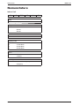
Table of Contents
Table of Contents
Nomenclature......................................................................................................................1
Indoor Unit .....................................................................................................................1
Outdoor Unit ..................................................................................................................2
Product Line-Up.............................................................................................................3
Features...............................................................................................................................7
Application Information .....................................................................................................8
Operating Range ...........................................................................................................8
Refrigerant Circuit Diagram ...........................................................................................9
Controller ....................................................................................................................13
Installation Guideline ...................................................................................................14
Sound Data........................................................................................................................24
Sound Pressure Level .................................................................................................24
NC Curve .....................................................................................................................25
Engineering & Physical Data ...........................................................................................28
General Data ...............................................................................................................28
Component Data .........................................................................................................34
Performance Data .............................................................................................................40
Calculation Steps.........................................................................................................41
Performance Data .......................................................................................................46
Outline and Dimension ....................................................................................................64
Electrical Data ...................................................................................................................66
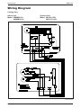
Wiring Diagram .................................................................................................................69
Service and Maintenance.................................................................................................73
Troubleshooting ...............................................................................................................75
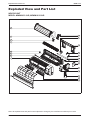
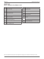
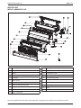
Exploded View and Part List ...........................................................................................83
“McQuay” is a registered trademark of McQuay International. All rights reserved.
© 2011 McQuay International. All rights reserved throughout the world.
Bulletin illustrations cover the general appearance of McQuay International products at the time of publication.
We reserve the right to change design and construction specifications at any time without notice.
Nomenclature
MWM-J-2011
Nomenclature
Indoor Unit
M
5
WM
10
Brand
M
: Mcquay
Refrigerant
“ “
4
5
: Omitted if R22
: R407C
: R410A
Model Name
WM
: Wall Mounted
Capacity Index
10
15
20
25
: 10,000 Btu/h
: 15,000 Btu/h
: 20,000 Btu/h
: 25,000 Btu/h
Series
G
J
: G Series
: J Series
Model Type
“ “
R
1
: Omitted if cooling only
: Heatpump
J
R
MWM-J-2011
Nomenclature
Outdoor Unit
M
5
LC
10
C
R
Brand
M
: Mcquay
Refrigerant
“ “
4
5
: Omitted if R22
: R407C
: R410A
Model Name
LC
: Single Split Condensing Unit
Capacity Index
10
15
20
25
: 10,000 Btu/h
: 15,000 Btu/h
: 20,000 Btu/h
: 25,000 Btu/h
Series
C
: C Series
Model Type
“ “
R
: Omitted if cooling only
: Heatpump
2
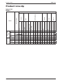
Product Line-Up
MWM-J-2011
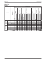
Product Line-Up
Indoor Unit
MWM-J
3
CE
A
ACLAA
X
X
X
X
X
15J
ACLAA
X
X
X
X
X
20J
ACLAA
X
X
X
X
X
25J
ACLAA
X
X
X
X
X
09JR
ACLAA
X
X
X
X
X
15JR
ACLAA
X
X
X
X
X
20JR
ACLAA
X
X
X
X
X
25JR
ACLAA
X
X
X
X
X
Others
Grille
Marking
Air Purification
09J
Bio Filter
Saranet Filter
PCB
LGSN
Nomenclature
G17
HEATPUMP
COOLING
ONLY
MWM
Handset
Classification
MWM-J-2011
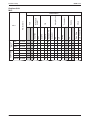
Product Line-Up
Indoor Unit
M5WM-J
CE
ACLAA
X
X
X
X
X
15J
ACLAA
X
X
X
X
X
10JR
ACLAA
X
X
X
X
X
15JR
ACLAA
X
X
X
X
X
Others
Marking
A
10J
Bio Filter
Saranet Filter
Grille
Air Purification
Handset
G17
PCB
LGSN
HEATPUMP
COOLING
ONLY
M5WM
Nomenclature
Classification
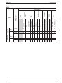
4
5
Cap Tube
09C
ACPOH
X
X
X
X
15C
ACPOH
X
X
X
X
020C
ACPOD
X
X
X
X
025C
ACPOD
X
X
X
X
09CR
ACPOH
X
X
X
X
X
15CR
ACPOJ
X
X
X
X
X
020CR ACPOD
X
X
X
X
X
025CR ACPOD
X
X
X
X
X
Low Ambient Kit
Drain Elbow
LP
HP
Contactor
Aluminium Fin
Blue Fin
Gold Fin
Others
Marking
Compressor
Safety Devices
FIN
Refrigerant
Control
PCB
Nomenclature
MLC
EXV
CE
COOLING
ONLY
Rotary
HEATPUMP
Product Line-Up
MWM-J-2011
Outdoor Unit
MLC
Classification
HEATPUMP
COOLING
ONLY
15CJ
10CRJ
15CRJ
ACPGG
X
X
X
X
ACPOG
X
X
X
X
ACPGG
X
X
X
X
ACPOG
X
X
X
X
ACPOG
X
X
X
X
ACPOG
X
X
X
X
Low Ambient Kit
Drain Elbow
LP
HP
Contactor
Bare
Blue Coated
Gold Coated
EXV
CE
10CJ
Rotary
Cap Tube
M5LC
Others
Marking
Compressor
Safety Devices
FIN
Refrigerant
Control
PCB
Nomenclature
MWM-J-2011
Product Line-Up
Outdoor Unit
M5LC
Classification
X
X
6
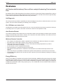
Features
MWM-J-2011
Features
Air Filtration with Bio Antibody Filter and Photo-catalytic Deodorizing Titanium Apatite
Filter
Bio Antibody Filter is effective against various airborne infectious viruses while Titanium Apatite Filter is able to
trap microscopic particles as well as break down and decompose odors. The filter can be used for approximately
3 years without replacement if wash about once every six months.
Self Diagnosis
The microprocessor provides the possibility to detect and diagnose any fault or malfunction that occurs in the
system. The error will be reflected by the blinking of the LED lights.
On / Off Button on Indoor Unit
On/Off button is provided on the front panel of the unit. It can be used when the remote controller is missing or
if its battery has run out. (Note: This button can also be used for forced operation mode)
Auto Random Restart
Auto random restart function allows the unit to automatic restart as the last setting condition when the power
supply is resumed after power failure. However, the compressor will restart randomly if more than one unit is
installed and sharing the same phase of power.
Wireless Remote Controller
• The compact LCD transmitter is able to operate the air conditioner unit within the distance of 8 meters.
• Fan speed can be set at high / medium / low / super low or automatic.
• Sleep mode auto control will gradually increase or decrease the setting temperature to provide a
comfortable surrounding for sleeping.
• Air flow direction can be controlled automatically.
• Room temperature is controlled by electronic thermostat.
• The real time timer allows the air conditioner to be switched On and Off automatically based on user
settings.
• Turbo mode function is available to enables the required set temperature to be achieved in a short time.
• Personalized Setting allows user to preset and store 2 groups of personal settings (including timer setting)
in the handset.
Energy Efficiency
Using a more efficient compressor and superior R410A refrigerant, M5WM10JR series achieves the highest
European Energy Rating of A/A. This ensures higher energy savings is accomplished especially during daily
usage. M5WM-J series participates in the Eurovent Certification Programme under category of Comfort Air
Conditioners rated below 12kW cooling capacity (AC1). The certified data for the certified models are listed in
the Eurovent Directory.
7
MWM-J-2011
Application Information
Application Information
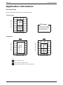
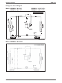
Operating Range
Ensure the operating temperature is in allowable range.
Cooling only
Outdoor temp. (°CDB)
46
Standard
point
35
!
Caution :
19
The use of your air conditioner
outside the range of working
temperature and humidity can
result in serious failure.
Low ambient kit
-5
23
14
Indoor temp. (°CWB)
Heatpump
Cooling
Heating
Outdoor temp. (°CDB)
Outdoor temp. (°CWB)
18
Standard
point
6
-9
46
Standard
point
35
19
Low ambient kit
-5
16
21
30
Indoor temp. (°CDB)
14
23
Indoor temp. (°CWB)
Note :
Standard operating range.
With Low ambient kit. (Optional item)
Please refer to local dealer for unit of this specification.
8
Application Information
MWM-J-2011
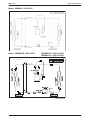
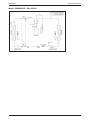
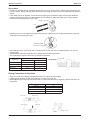
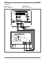
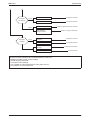
Refrigerant Circuit Diagram
Model: MWM09J - MLC09C
MWM15J - MLC15C
M5WM10J - M5LC10CJ
M5WM15J - M5LC15CJ
70034 049971
Model: MWM20J - MLC020C
9
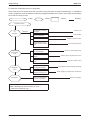
MWM-J-2011
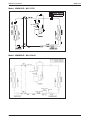
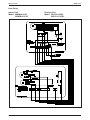
Application Information
Model: MWM25J - MLC025C
Model: MWM09JR - MLC09CR
M5WM10JR - M5LC10CRJ
M5WM15JR - M5LC15CRJ
70034 023154
10
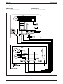
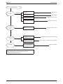
Application Information
MWM-J-2011
Model: MWM15JR - MLC15CR
70034 095236
Model: MWM20JR - MLC020CR
11
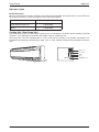
MWM-J-2011
Application Information
Model: MWM025JR - MLC025CR
12
Application Information
MWM-J-2011
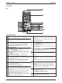
Controller
G17
1
2
P1 P2
10
9
3
8
MODE
4
SLEEP
7
5
CANCEL
SET
OFF TIMER
13
ON TIMER
SET
14
12
CANCEL
6a 6b
11
15
Operation Guide
1
Transmission Source
• The source where the signal will be transmitted.
2
Signal Transmission Indication
• Blink to confirm that the last setting has been transmitted
to the unit.
3
Temperature Setting
• To set the desired room temperature, press the v or V
button to increase orde crease the set temperature.
• The temperature setting range is from 16°C to 30°C
(optional setting 20°C to 30°C).
4
Personalize Setting
10 “ON/OFF” Button
• Press and hold for 3s, then will blink. Press again to
• Press one to start the air conditioner unit.
cycle between and
• Press again to stop the unit.
• Set the desire setting, then leave the hand set for 4s
without pressing any key and it will save the setting into the
11 Timer Cancel
programme.
• Press once to activate the P1 setting, press again to
• Press the TIMER CANCEL button to cancel the on timer
cycle between P1 and P2.
setting.
• Press any key to deactivate the personalize setting.
12 OFF Timer Setting
Automatic Air Swing (optional)
• Press the OFF TIMER button will activate the off timer
• Press the SWING button to activate the automatic air
function.
swing function.
• Set the desired off time by pressing the OFF TIMER button
• To distribute the air to a specific direction, press the
continuously.
SWING
button and wait until the louver move to the
desired direction and press the button once again.
13 ON Timer Setting
Silent Function
• Press the ON TIMER button will activate the on timer
• Press for quiet operation.
function.
• Fan speed turn to minimum speed.
• Set the desired on time by pressing the ON TIMER
• Press again to deactivate the function.
button continuously. If the timer is set to 7.30am, the air
conditioner will turn on at 7.30am sharp.
Sleep Mode Setting
5
6
7
• Press the SLEEP button will activate the sleep mode
function. This function is available under COOL, HEAT and
AUTO mode.
• When the unit is operating under cooling mode, the set
temperature is increased by 0.5°C after 30 minutes, 1°C
after an hour, and 2°C after 2 hours.
• When the unit is operating under heating mode, the set
temperature is decreased by 1°C after 30 minutes, 2°C
after an hour, and 3°C after 2 hours.
13
8
Operating Mode
• Press the MODE button to select the type of operating
mode.
• For cooling only unit, the available modes are: COOL (7),
DRY (6) and FAN ( ).
9
Fan Speed Selection
• Press the
button continuously will toggle the fan speed
in the following order:
Low p Med p High p Auto
• Stop pressing when the desired fan speed appears on the
display screen.
14 Turbo Function
• Press
for fast cooling.
• Fan speed turn to maximum speed.
• Press again to deactivate the function.
15 Clock Time Setting
• Press
and hold to set the clock time.
MWM-J-2011
Application Information
Installation Guideline
Safety Precautions
WARNING
CAUTION
• Installation and maintenance should be performed by
qualified persons who are familiar with local code and
regulation, and experienced with this type of appliance.
• All field wiring must be installed in accordance with the
national wiring regulation.
• Ensure that the rated voltage of the unit corresponds
to that of the name plate before commencing wiring
work according to the wiring diagram.
• The unit must be GROUNDED to prevent possible
hazard due to insulation failure.
• All electrical wiring must not touch the refrigerant
piping or any moving parts of the fan motors.
• Confirm that the unit has been switched OFF before
installing or servicing the unit.
• Disconnect from the main power supply before
servicing the air conditioner unit.
• DO NOT pull out the power cord when the power is
ON. This may cause serious electrical shocks which
may result in fire hazards.
• Keep the indoor and outdoor units, power cable and
transmission wiring, at least 1m from TVs and radios,
to prevent distorted pictures and static. {Depending on
the type and source of the electrical waves, static may
be heard even when more than 1m away}.
Please take note of the following important points
when installing.
• Do not install the unit where leakage of flammable
gas may occur.
If gas leaks and accumulates around the unit, it
may cause fire ignition.
• Ensure that drainage piping is connected properly.
If the drainage piping is not connected properly,
it may cause water leakage which will dampen
the furniture.
• Do not overcharge the unit.
This unit is factory pre-charged. Overcharge will
cause over-current or damage to the compressor.
• Ensure that the unit’s panel is closed after service
or installation.
Unsecured panels will cause the unit to operate
noisily.
• Sharp edges and coil surfaces are potential
locations which may cause injury hazards. Avoid
from being in contact with these places.
• Before turning off the power supply, set the remote
controller’s ON/OFF switch to the “OFF” position
to prevent the nuisance tripping of the unit. If this is
not done, the unit’s fans will start turning automatically
when power resumes, posing a hazard to service
personnel or the user.
• Do not operate any heating apparatus too close to the
air conditioner unit. This may cause the plastic panel to
melt or deform as a result of the excessive heat.
• Ensure the color of wires of the outdoor unit and
the terminal markings are same to the indoors
respectively.
• IMPORTANT : DO NOT INSTALL OR USE THE
• AIR CONDITIONER UNIT IN A LAUNDRY ROOM.
• Do not use joined and twisted wires for incoming
power supply.
NOTICE
Disposal requirements
Your air conditioning product is marked with this symbol. This means that electrical and electronic products
shall not be mixed with unsorted household waste.
Do not try to dismantle the system yourself: the dismantling of the air conditioning system, treatment of
the refrigerant, of oil and of other parts must be done by a qualified installer in accordance with relevant
local and national legislation. Air conditioners must be treated at a specialized treatment facility for re-use,
recycling and recovery. By ensuring this product is disposed of correctly, you will help to prevent potential
negative consequences for the environment and human health. Please contact the installer or local authority
for more information.
Batteries must be removed from the remote controller and disposed of separately in accordance with relevant
local and national legislation.
14
Application Information
MWM-J-2011
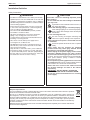
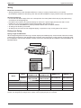
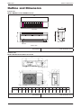
Installation Diagram
Indoor Unit
30mm or more from ceiling
Caulk pipe
hole gap
with putty.
Front panel
Wrap the insulation pipe with
the finishing tape from bottom
to top.
50mm or more from walls
(on both sides)
Air filter
Cut thermal insulation
pipe to an appropriate
length and wrap it with
tape, making sure that no
gap is left in the insulation
pipe's cut line.
M4 x 12L
Service lid
Opening service lid
Service lid is opening/closing
type.
Opening method
1) Remove the service lid
screws.
2) Pull out the service lid
diagonally down in
thedirection of the arrow.
1) Pull down.
Air-Purifying Filter with
bacteriostatic virustatic function (2)
Air-Purifying Filter with
bacteriostatic virustatic
function
Filter frame
Air filter
Tab
Outdoor Unit
250mm from wall
Caution
• Before installing the unit, ensure that the power supply matches the power requirement of the air conditioner.
Installation of Indoor Unit
Service Space
Install the indoor unit at a location with the following requirements
• Location is suitable for wiring, piping and drainage.
• No obstruction of air flow into and out of unit where cooler air can be evenly distributed.
• Ensure that air discharge is not short circuited with air intake.
• Ensure that wall is sufficiently strong, rigid, flat, perpendicular and vibration free.
• Where air filter cassette can be slided in or out easily.
• Where there is no danger of flammable gases.
• Where there is no direct sunlight on unit.
min. 50
(Space for
maintenance)
15
min. 30
(Space for
performance)
Air flow
(Indoor)
Required space
min. 50
(Space for
maintenance)
MWM-J-2011
Application Information
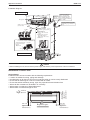
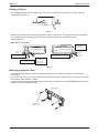
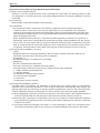
Routing of Piping
• The refrigerant piping can be routed to the unit in one of 5 directions, by using the cut outs in the unit
casing (refer to Figure 1).
3
2
1
4
5
Figure 1
• Carefully bend the pipes to the required position to align with the hole. For right hand and rear side draw
out, hold the bottom of the piping and fix direction before shaping it to the desired position
(refer to Figure 2).
Right & Rear Side Routing
Remove pipe port
cover here for
left-side piping
Left-side
piping
Right-side
piping
Remove pipe port cover
here for right-side piping
Right-back piping
Right-bottom
piping
Remove pipe port cover
here for right-bottom piping
Remove pipe port cover here for
left-bottom piping
Left-back
piping
Left-bottom piping
Bind coolant pipe
and drain hose
together with
insulating tape.
Figure 2
Mounting Installation Plate
• Paste the installation plan provided on the desired location on the wall and marks the holes location
accordingly.
• Ensure the wall is strong enough to withstand the weight of the unit. Otherwise, it is necessary to reinforce
the wall with plates, beams or pillars.
• Ensure the levelness of the installation plate, and fix with 5 suitable screws for M(5)WM09/10/15J/JR and 7
suitable screws for MWM20/25J/JR.
Mounting plate
Mounting plate
fixing screw
16
Application Information
MWM-J-2011
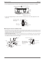
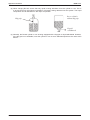
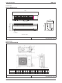
• Fix the installation plate firmly to the wall, without tilting to left or right. Use a plumb line, if available.
Use tape measure as shown.
Position the end of a tape measure
at
184
Recommended mounting plate
retention spots (5 spots in all)
42.2
42.2
42.2
166
45.9
45.9
288
Through
the wall
hole
Ø 65mm
54.5
153.8
263
51.9
181.7
555
800
Liquid pipe end
Gas pipe end
Drain
hose
position
All dimensions are in mm
• In case of rear piping drawings out, drill a hole 65mm in diameter with a cone drill, slightly lower on the
outside wall.
Hole with cone drill
Wall embedded pipe
(Field supply)
Inside
Outside
Caulking
Ø 65
Wall hole cover
(Field supply)
Wall embedded pipe
(Field supply)
Mounting Unit onto the Installation Plate
• Hook the indoor unit onto the upper portion of the installation plate (engage the two hooks at the rear top of
the indoor unit with the upper edge of the installation plate). Ensure the hooks are properly seated onto the
installation plate by moving it to the left and right.
• To attach the indoor unit, hook the claws of the bottom frame to the mounting plate. If the claws are difficult
to hook, remove the front grille.
• To remove the indoor unit, push the marked area (at the lower part of the front grille) to release the claws.
If it is difficult to release, remove the front grille.
Mounting
plate
Clip
Bottom frame
Front grille
17
Hang indoor unit's hook here.
Mounting plate
When stripping the
ends of interconnecting
wires in advance, bind
right ends of wires with
insulating tape.
Interconnecting
wires
Wire guide
Mark (rear side)
MWM-J-2011
Application Information
Water Drainage Piping
• The indoor drain pipe must be downward gradient for smooth drainage. Avoid situation as shown in figure
below.
Water Drainage
Water
Retention
Water
leaking
Water
leaking
Water
leaking
End
dipped
into
water
Drain
Correct
Wrong
Wrong
Wrong
Installation of Outdoor Unit
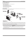
Condensed Water Disposal of Outdoor Unit (Heat Pump Unit Only)
• There are 2 holes on the base of outdoor unit for condensed water to flow out. Insert the drain elbow to
one of the holes.
• To install the drain elbow, first insert one portion of the hook to the base (portion A), the pull the drain elbow
in the direction shown by the arrow while inserting the other portion to the base. After installation, check to
ensure that the drain elbow clings to base firmly.
• If the unit is installed in a snowy and chilly area, condensed water may freeze in the base. In such case,
please remove plug at the bottom of unit to smooth the drainage.
A
18
Application Information
MWM-J-2011
As condensing temperature rises, evaporating temperature rises and cooling capacity drops. In order to achieve
maximum cooling capacity, the location selected for outdoor unit should fulfill the following requirements:
• Install the condensing (outdoor) unit in a way such that hot air distributed by the outdoor condensing unit
cannot be drawn in again (as in the case of short circuit of hot discharge air). Allow sufficient space for
maintenance around the unit.
• Ensure that there is no obstruction of air flow into or out of the unit. Remove obstacles which block air
intake or discharge.
• The location must be well ventilated, so that the unit can draw in and distribute plenty of air thus lowering
the condensing temperature.
• A place capable of bearing the weight of the outdoor unit and isolating noise and vibration.
• A place protected from direct sunlight. Otherwise use an awning for protection, if necessary.
• The location must not be susceptible to dust or oil mist.
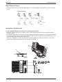
Installation Clearance
• Outdoor units must be installed such that there is no short circuit of the hot discharge air or obstruction to
smooth air flow. Select the coolest possible place where intake air should not be hotter than the outside
temperature (max. 45˚C).
ALL MODELS
Minimum Distance
A
B
C
D
300 mm
1000 mm
300 mm
500 mm
CAUTION : If the condensing unit is operated in an atmosphere containing oils (including machine oils), salt (coastal area),
sulphide gas (near hot spring, oil refinery plant), such substances may lead to failure of the unit.
19
MWM-J-2011
Application Information
Wiring
Electrical Connections
• Wiring regulations on wire diameters differ from country to country. Please refer to your LOCAL
ELECTRICAL CODES for field wiring rules. Be sure that installations comply with the rules and regulations.
General Precautions
• Ensure that the rated voltage of the unit corresponds to the name plate before carrying out proper wiring
according to the wiring diagram.
• Provide a power outlet to be used exclusively for each unit. A power supply disconnects and a circuit
breaker for over-current protection should be provided in the exclusive line.
• The unit must be GROUNDED to prevent possible hazards due to insulation failures.
• All wiring must be firmly connected.
• All wiring must not touch the hot refrigerant piping, compressor or any moving parts of fan motors.
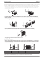
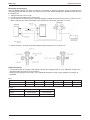
Refrigerant Piping
Piping Length and Elevation
When the pipe length becomes too long, both the capacity and reliability drop. As the number of bends increases,
system piping resistance to the refrigerant flow increases, thus lowering the cooling capacity, and as the result
the compressor may become defective. Always choose the shortest path and follow the recommendation as
tabulated below:
Indoor Unit
Outdoor Unit
L
H
Indoor
MWM09J/JR
M5WM10J/JR
MWM15J/JR
M5WM15J/JR
MWM20J/JR
MWM25J/JR
Outdoor
MLC09C/CR
M5LC10C/CR
MLC15C/CR
M5LC15C/CR
MLC020C/CR
MLC025C/CR
Min. Allowable Length, m (L)
3
3
3
3
Max. Allowable Length, m (L)
15
15
15
15
Max. Allowable Height, m (H)
Liquid, mm/in
10
6.35 / 1/4
10
6.35 / 1/4
8
9.52 / 3/8
8
9.52 / 3/8
Suction, mm/in
9.52 / 3/8
12.70 / 1/2
15.87 / 5/8
15.87 / 5/8
Model
* Be sure to add the proper amount of additional refrigerant. Failure to do so may result in reduced performance
Remark: The refrigerant pre-charged in the outdoor unit is for piping length up to 7.6m/25ft.
20
Application Information
MWM-J-2011
Piping Works
• Do not use contaminated or damaged copper tubing. Do not remove plastic, rubber plugs and brass nuts
from the valves, fittings, tubings and coils until you are ready to connect suction or liquid line into valves or
fittings.
• If any brazing work is required, ensure that the nitrogen gas is passed through coil and joints while the
brazing work is being done. This will eliminate soot formation on the inside walls of the copper tubings.
• Cut the connection pipe with a pipe cutter.
Cutting copper tube
1/4t
• Remove burrs from cut edges of the pipes with remover. Hold the end of the pipe downwards to prevent
metal chips from entering the pipe.
Remove burr
• Insert the flare nuts, mounted on the connection parts of both the indoor unit and outdoor unit onto the
copper pipes.
• Flare the pipe with extra length above the flaring tool as shown in the table.
• The flared edge must be even and not cracked or scratched.
Ø Tube,
D (mm / in)
A (mm)
Copper tube
Imperial Die
Rigid Die
6.35 / 1/4
1.3
0.7
9.52 / 3/8
1.6
1.0
12.70 / 1/2
1.9
1.3
15.88 / 5/8
2.2
1.7
Swaging block
Piping Connection to the Units
• Align the center of the piping and tighten the flare nut sufficiently with fingers.
• Finally tighten the flare nut with torque wrench unit the wrench clicks.
• When tightening the flare nut with torque wrench, ensure the direction for tightening follows the arrow on
the wrench.
Flare joint
Indoor piping
Pipe Size (mm/in)
Torque (Nm)
6.35 (1/4)
18
9.52 (3/8)
42
12.70 (1/2)
55
15.88 (5/8)
65
Flared tube
Flare nut
Spanar
21
Torque wrench
MWM-J-2011
Application Information
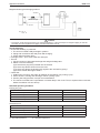
Vacuuming and Charging
The pre-charged outdoor unit does not need any vacuuming or charging. However once it is connected, the
connecting pipe line and the indoor unit need to be vacuumed before releasing the R22/R407C/R410A from
the outdoor unit.
1. Open the service port core cap.
2. Connect pressure gauge to the service port.
3. Connect the line to vacuum pump. Open the charging manifold valve and turn the pump on. Vacuum to -0.1
MPa (-760mmHg) or lower. (Evacuation time varies by the pump but averagely in 1 hour).
Filter Dryer
(Mclecular-Sieve Type
Note : R22 - Nil
R410A - Nil
4. After evacuation, unscrew the spindle (diagram B) for the gas to run to indoor unit.
Additional Charge
• The refrigerant gas is charged in the outdoor unit and, if the piping length is 7.6m, additional charge of the
refrigerant after vacuuming is not necessary.
• When the piping length is more than 7.6m, additional refrigerant charge (g) per additional 1m length as
tabulated:
R22
Indoor
MWM09J/JR
MWM15J/JR
MWM20J
MWM25J
MWM20JR
MWM25JR
Outdoor
MLC09C/CR
MLC15C/CR
MLC020C
MLC025C
MLC020CR
MLC025CR
16
23
15
22
39
55
Additional Charge (g/m)
R410A
Indoor
M5WM10J/JR
M5WM15J/JR
Outdoor
M5LC10C/CR
M5LC15C/CR
9
6
Additional Charge (g/m)
22
Application Information
MWM-J-2011
Diagram shows typical charging method:
(Mclecular-Sieve Type)
Note : R22 - Nil
R410A - Nil
Caution
• For R410A, avoid prolong exposure of an opened compressor, or the internal part of refrigerant piping to moist air.
The POE oil in the compressor and piping can absorb moisture from air.
Overall Checking
• Ensure the following, in particular:
1. The unit is mounted solidly and rigid in position.
2. Piping and connections are leak proof after charging.
3. Proper wiring has been done.
• Drainage check – pour some water into drain pan.
• Test run
1. Conduct a test run after water drainage test and gas leakage test.
2. Watch out for the following:
(a) Is the electric plug firmly inserted into the socket?
(b) Is there any abnormal sound from the unit?
(c) Is there any abnormal vibration with regard to the unit itself or piping?
(d) Is there smooth drainage of water?
• Check that:
1. Outdoor fan is running, with warm air blowing off the outdoor unit (cooling cycle).
2. Indoor blower is running and discharge cool air (cooling cycle).
3. Suction (low side) pressure is as per recommendations.
4. The remote controller has incorporated a 3 minutes delay in the circuit. Thus, it requires about 3 minutes
before the outdoor unit can start up.
Standard Operating Condition
Cooling only unit
Temperature
Ts °C / °F
Th °C / °F
Minimum indoor temperature
19.0 / 66.2
14.0 / 57.2
Maximum indoor temperature
32.0 / 89.6
23.0 / 73.4
Minimum outdoor temperature
19.4 / 66.9
-
Maximum outdoor temperature
46.0 / 114.8
-
Temperature
Ts °C / °F
Th °C / °F
Minimum indoor temperature
16.0 / 60.8
-
Maximum indoor temperature
30.0 / 86.0
-
Minimum outdoor temperature
-8.0 / 17.6
-9.0 / 15.8
Maximum outdoor temperature
24.0 / 75.2
18.0 / 64.4
Heat pump unit
Ts : Dry bulb temperature
23
Th : Wet bulb temperature
MWM-J-2011
Application Information
Special Precautions When Dealing With Refrigerant R410A Unit
(1) What is new refrigerant R410A?
R410A is a new HFC refrigerant which does not damage the ozone layer. The working pressure of this
new refrigerant is 1.6 times higher than conventional refrigerant (R22), thus proper installation / servicing
is essential.
(2) Components
Mixture weight composition R32(50%) and R125(50%)
(3) Characteristic
• R410A liquid and vapor components have different compositions when the fluid evaporates or
condenses. Hence, when leak occurs and only vapor leaks out, the composition of the refrigerant
mixture left in the system will change and subsequently affect the system performance. DO NOT add
new refrigerant to leaked system. It is recommended that the system should be evacuated thoroughly
before recharging with R410A.
• When refrigerant R410A is used, the composition will differ depending on whether it is in gaseous or
liquid phase. Hence when charging R410A, ensure that only liquid is being withdrawn from the cylinder
or can. This is to make certain that only original composition of R410A is being charged into the system.
• POE oil is used as lubricant for R410A compressor, which is different from the mineral oil used for R22
compressor. Extra precaution must be taken not to expose the R410A system too long to moist air.
(4) Check list before installation / servicing
• Tubing
Refrigerant R410A is more easily affected by dust of moisture compared with R22, make sure to
temporarily cover the ends of the tubing prior to installation.
• Compressor oil
No additional charge of compressor oil is permitted.
• Refrigerant
No other refrigerant other that R410A
• Tools (size of service port is different from R22 system)
Tools specifically for R410A only (must not be used for R22 or other refrigerant)
i) Gauge manifold and charging hose
ii) Gas leak detector
iii) Refrigerant cylinder/charging cylinder
iv) Vacuum pump c/w adapter
v) Flare tools
vi) Refrigerant recovery machine
(5) Handling and installation guidelines
Like R22 system, the handling and installation of R410A system are closely similar. All precautionary
measures; such as ensuring no moisture, no dirt or chips in the system, clean brazing using nitrogen, and
thorough leak check and vacuuming are equally important requirements. However, due to its hydroscopic
POE oil, additional precautions must be taken to ensure optimum and trouble free system operation.
(a) During installation or servicing, avoid prolong exposure of the internal part of the refrigerant system to
moist air. Residual POE oil in the piping and components can absorb moisture from the air.
(b) Ensure that the compressor is not exposed to open air for more than the recommended time specified
by its manufacturer (typically less than 10 minutes). Removed the seal plugs only when the compressor
is about to be brazed.
(c) The system should be thoroughly vacuumed to 1.0 Pa (700mmHg) or lower. This vacuuming level is
more stringent than R22 system so as to ensure no incompressible gas and moisture in the system.
24
Application Information
MWM-J-2011
(d) When charging R410A, ensure that only liquid is being withdrawn from the cylinder or can. This is
to ensure that only the original composition of R410A is being delivered into the system. The liquid
composition can be different from the vapor composition.
Dip-pipe
Invert cylinder
without dip-pipe
Liquid
withdrawal
(e) Normally, the R410A cylinder or can is being equipped with a dip pipe for liquid withdrawal. However,
if the dip pipe is not available, invert the cylinder or can so as to withdraw liquid from the valve at the
bottom.
25
MWM-J-2011
Sound Data
Sound Data
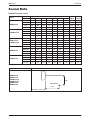
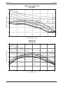
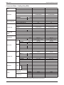
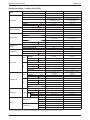
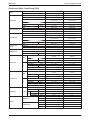
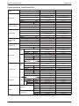
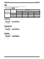
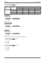
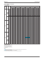
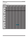
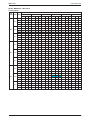
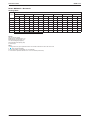
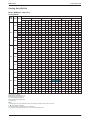
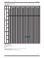
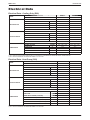
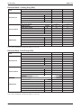
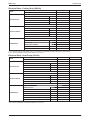
Sound Pressure Level
Speed
Model
(RPM)
MWM09J/JR
M5WM10J/JR
MWM15J/JR
M5WM15J/JR
MWM20J/JR
MWM25J/JR
1/1 Octave Sound Pressure Level (dB, ref 20μPa)
125 Hz 250 Hz 500 Hz 1k Hz
2k Hz
4k Hz
Overall Noise
8k Hz (dBA) Criteria
High
30
32
33
29
25
19
9
34
28
Medium
27
29
31
27
22
20
11
32
25
Low
24
26
28
23
19
19
11
29
22
S. Low
24
25
27
22
18
19
11
28
22
High
31
35
36
34
30
22
9
38
33
Medium
26
30
31
27
22
13
5
32
25
Low
24
26
27
22
15
7
7
27
21
S. Low
23
24
25
20
13
6
5
25
-
High
32
35
36
34
31
22
11
38
33
Medium
30
32
33
29
25
16
10
34
28
Low
29
28
28
24
19
11
10
29
22
S. Low
28
26
27
22
17
9
9
27
21
High
21
31
36
38
36
27
15
42
37
Medium
17
28
34
35
32
23
13
39
34
Low
14
26
31
32
29
20
12
36
32
S. Low
12
25
31
31
27
20
13
35
30
High
40
42
42
42
39
32
20
46
43
Medium
37
39
39
39
36
27
19
43
39
Low
34
37
37
36
32
24
18
40
37
S. Low
31
35
35
33
29
22
18
37
33
Microphone position: 1m in front and 0.8m below the vertical centre line of the unit. (JIS C 9612)
Model
Measuring location
MWM09J/JR
MWM15J/JR
M5WM10J/JR
M5WM15J/JR
MWM20J/JR
MWM25J/JR
0.8m
Microphone
1.0m
Standard : JIS C 9612
24
Sound Data
MWM-J-2011
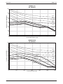
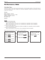
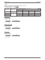
MWM09J/JR
NC CURVES
60
Sound pressure level (dB,ref20µPa)
50
NC-45
40
NC-40
NC-35
High Fan
30
Medium Fan
NC-30
Low Fan
NC-25
S.Low Fan
20
NC-20
10
0
125
250
500
1000
2000
4000
8000
Octave-band frequency (Hz)
M5WM10J/JR
NC CURVES
60
50
Sound pressure level (dB,ref20µPa)
NC-45
40
NC-40
NC-35
High Fan
30
NC-30
Medium Fan
NC-25
Low Fan
20
NC-20
S.Low Fan
10
0
125
250
500
1000
Octave-band frequency (Hz)
25
2000
4000
8000
MWM-J-2011
Sound Data
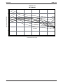
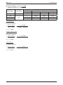
MWM15J/JR, M5WM15J/JR
NC CURVES
60
Sound pressure level (dB, ref20µPa)
50
NC45
40
NC-40
30
High Fan
NC-35
Medium Fan
NC-30
NC-25
Low Fan
20
NC-20
S.Low Fan
10
0
125
250
500
1000
2000
4000
8000
Octave-band frequency (Hz)
M5WM20J/JR
NC CURVES
60
Sound pressure level (dB,ref20µPa)
50
NC-45
40
NC-40
NC-35
High Fan
30
NC-30
Medium Fan
NC-25
Low Fan
20
NC-20
S.Low Fan
10
0
125
250
500
1000
2000
4000
8000
Octave-band frequency (Hz)
26
Sound Data
MWM-J-2011
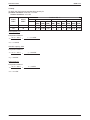
MWM25J/JR
NC CURVES
60
Sound pressure level (dB,ref20µPa)
50
NC-45
40
NC-40
High Fan
NC-35
Medium Fan
NC-30
30
NC-25
Low Fan
20
NC-20
S.Low Fan
10
0
125
250
500
1000
Octave-band frequency (Hz)
27
2000
4000
8000
MWM-J-2011
Engineering & Physical Data
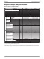
Engineering & Physical Data
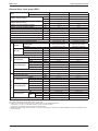
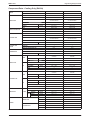
General Data - Cooling Only (R22)
INDOOR UNIT
MODEL
OUTDOOR UNIT
NOMINAL CAPACITY
MWM09J
MWM15J
MLC09C
MLC15C
Btu/h
8400
12000
W
2460
3520
1176
NOMINAL TOTAL INPUT POWER
W
925
NOMINAL RUNNING CURRENT
A
4.10
5.40
V/Ph/Hz
220 - 240 / 1 / 50
220 - 240 / 1 / 50
W/W
3.11
3.20
POWER SOURCE
EER
REFRIGERANT TYPE
REFRIGERANT CONTROL (EXPANSION DEVICE)
CONTROL
AIR DISCHARGE
OPERATION
INDOOR UNIT
AIR FLOW
R22
OUTDOOR CAP. TUBE
AUTO LOUVER (UP & DOWN) &
GRILLE (LEFT & RIGHT)
AUTO LOUVER (UP & DOWN) &
GRILLE (LEFT & RIGHT)
LCD REMOTE CONTROL
LCD REMOTE CONTROL
HIGH
l/s / CFM
145 / 309
163 / 346
MEDIUM
l/s / CFM
125 / 265
138 / 293
LOW
l/s / CFM
105 / 223
113 / 240
38 / 34 / 29
SOUND PRESSURE LEVEL (H/M/L)
UNIT DIMENSION
PACKING DIMENSION
dBA
34 / 32 / 29
HEIGHT
mm/in
288 / 11.3
288 / 11.3
WIDTH
mm/in
800 / 31.5
800 / 31.5
DEPTH
mm/in
204 / 8.0
204 / 8.0
HEIGHT
mm/in
350 / 13.8
350 / 13.8
WIDTH
mm/in
874 / 34.4
874 / 34.4
DEPTH
mm/in
280 / 11.0
280 / 11.0
12 / 26.5
UNIT WEIGHT
kg/lb
12 / 26.5
mm/in
16 / 0.6
16 / 0.6
l/s / CFM
349 / 740
457 / 969
dBA
45
49
HEIGHT
mm/in
475 / 18.7
540 / 21.3
WIDTH
mm/in
600 / 23.6
700 / 27.6
DEPTH
mm/in
245 / 9.6
250 / 9.8
HEIGHT
mm/in
535 / 21.1
620 / 24.4
WIDTH
mm/in
712 / 28.0
810 / 31.9
DEPTH
mm/in
320 / 12.6
330 / 13.0
kg/lb
33 / 72.6
34 / 75.0
FLARE VALVE
FLARE VALVE
CONDENSATE DRAIN SIZE
AIR FLOW
SOUND PRESSURE LEVEL
UNIT DIMENSION
OUTDOOR UNIT
R22
OUTDOOR CAP. TUBE
PACKING DIMENSION
UNIT WEIGHT
TYPE
PIPE CONNECTION
REFRIGERANT CHARGE
SIZE
LIQUID
mm/in
6.4 / 1/4
6.4 / 1/4
GAS
mm/in
9.5 / 3/8
12.7 / 1/2
kg/lb
0.65 / 1.43
0.75 / 1.65
1) ALL SPECIFICATIONS ARE SUBJECTED TO CHANGE BY THE MANUFACTURER WITHOUT PRIOR NOTICE.
2) ALL UNITS ARE BEING TESTED AND COMPLY TO ISO 5151.
3) NOMINAL COOLING AND HEATING CAPACITY ARE BASED ON THE CONDITIONS BELOW :
COOLING - 27°C DB / 19°C WB INDOOR AND 35°C DB / 24°C WB OUTDOOR
4) SOUND PRESSURE LEVEL ARE ACCORDING TO JIS B 8615 STANDARD. POSITION OF THE MEASUREMENT POINT IS 1m IN FRONT AND 1m
BELOW THE UNIT.
28
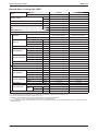
Engineering & Physical Data
MWM-J-2011
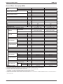
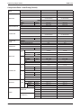
General Data - Cooling Only (R22)
MODEL
INDOOR UNIT
MWM20J
MWM25J
OUTDOOR UNIT
MLC020C
MLC025C
Btu/h
19500
24000
W
5720
7030
W
1850
2530
NOMINAL CAPACITY
NOMINAL TOTAL INPUT POWER
NOMINAL RUNNING CURRENT
POWER SOURCE
EER
A
8.21
11.30
V/Ph/Hz
220 - 240 / 1 / 50
220 - 240 / 1 / 50
W/W
3.29
3.22
R22
R22
REFRIGERANT TYPE
REFRIGERANT CONTROL (EXPANSION DEVICE)
CONTROL
AIR DISCHARGE
OPERATION
INDOOR UNIT
AIR FLOW
PACKING DIMENSION
LCD REMOTE CONTROL
LCD REMOTE CONTROL
l/s / CFM
252 / 536
290 / 616
MEDIUM
l/s / CFM
225 / 478
253 / 537
LOW
l/s / CFM
200 / 424
223 / 474
dBA
42 / 39 / 36
43 / 39 / 37
HEIGHT
mm/in
310 / 12.2
310 / 12.2
WIDTH
mm/in
1065 / 41.9
1065 / 41.9
DEPTH
mm/in
224 / 8.8
224 / 8.8
HEIGHT
mm/in
370 / 14.6
370 / 14.6
WIDTH
mm/in
1121 / 44.1
1121 / 44.1
DEPTH
mm/in
285 / 11.2
285 / 11.2
UNIT WEIGHT
CONDENSATE DRAIN SIZE
AIR FLOW
SOUND PRESSURE LEVEL
OUTDOOR UNIT
UNIT DIMENSION
PACKING DIMENSION
kg/lb
14 / 30.8
14 / 30.8
mm/in
19.05 / 0.75
19.05 / 0.75
l/s / CFM
614 / 1300
755 / 1600
dBA
51
52
HEIGHT
mm/in
654 / 25.7
756 / 29.8
WIDTH
mm/in
855 / 33.7
855 / 33.7
DEPTH
mm/in
328 / 12.9
328 / 12.9
HEIGHT
mm/in
710 / 28.0
810 / 31.9
WIDTH
mm/in
990 / 39.0
990 / 39.0
DEPTH
mm/in
415 / 16.3
415 / 16.3
kg/lb
57 / 125.4
60 / 132.0
FLARE VALVE
FLARE VALVE
UNIT WEIGHT
TYPE
PIPE CONNECTION
REFRIGERANT CHARGE
OUTDOOR CAP. TUBE
AUTO LOUVER (UP & DOWN) &
GRILLE (LEFT & RIGHT)
HIGH
SOUND PRESSURE LEVEL (H/M/L)
UNIT DIMENSION
OUTDOOR CAP. TUBE
AUTO LOUVER (UP & DOWN) &
GRILLE (LEFT & RIGHT)
SIZE
LIQUID
mm/in
9.52 / 3/8
9.52 / 3/8
GAS
mm/in
15.87 / 5/8
15.87 / 5/8
kg/lb
1.63 / 3.59
1.72 / 3.78
1) ALL SPECIFICATIONS ARE SUBJECTED TO CHANGE BY THE MANUFACTURER WITHOUT PRIOR NOTICE.
2) ALL UNITS ARE BEING TESTED AND COMPLY TO ISO 5151.
3) NOMINAL COOLING AND HEATING CAPACITY ARE BASED ON THE CONDITIONS BELOW :
COOLING - 27°C DB / 19°C WB INDOOR AND 35°C DB / 24°C WB OUTDOOR
4) SOUND PRESSURE LEVEL ARE ACCORDING TO JIS B 8615 STANDARD. POSITION OF THE MEASUREMENT POINT IS 1m IN FRONT AND 1m
BELOW THE UNIT.
29
MWM-J-2011
Engineering & Physical Data
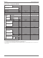
General Data - Heat pump (R22)
MODEL
INDOOR UNIT
MWM09JR
MWM15JR
OUTDOOR UNIT
MLC09CR
MLC15CR
Btu/h
8400
11800
NOMINAL COOLING CAPACITY
NOMINAL HEATING CAPACITY
W
2460
3460
Btu/h
9000
13000
W
2640
3810
NOMINAL TOTAL INPUT POWER (COOLING)
W
925
1192
NOMINAL TOTAL INPUT POWER (HEATING)
W
750
1064
NOMINAL RUNNING CURRENT (COOLING)
A
4.10
5.50
NOMINAL RUNNING CURRENT (HEATING)
A
3.40
4.90
POWER SOURCE
V/Ph/Hz
220 - 240 / 1 / 50
220 - 240 / 1 / 50
EER
W/W
3.11
3.20
COP
W/W
3.55
3.61
R22
R22
REFRIGERANT TYPE
REFRIGERANT CONTROL (EXPANSION DEVICE)
CONTROL
AIR DISCHARGE
OPERATION
INDOOR UNIT
AIR FLOW
OUTDOOR CAP. TUBE
AUTO LOUVER (UP & DOWN) &
GRILLE (LEFT & RIGHT)
LCD REMOTE CONTROL
LCD REMOTE CONTROL
HIGH
l/s / CFM
145 / 309
163 / 346
MEDIUM
l/s / CFM
125 / 265
138 / 293
LOW
l/s / CFM
105 / 223
113 / 240
38 / 32 / 27
SOUND PRESSURE LEVEL (H/M/L)
UNIT DIMENSION
PACKING DIMENSION
dBA
34 / 32 / 29
HEIGHT
mm/in
288 / 11.3
288 / 11.3
WIDTH
mm/in
800 / 31.5
800 / 31.5
DEPTH
mm/in
204 / 8.0
204 / 8.0
HEIGHT
mm/in
350 / 13.8
350 / 13.8
WIDTH
mm/in
874 / 34.4
874 / 34.4
DEPTH
mm/in
280 / 11.0
280 / 11.0
kg/lb
12 / 26.5
12 / 26.5
UNIT WEIGHT
CONDENSATE DRAIN SIZE
mm/in
16 / 0.6
16 / 0.6
l/s / CFM
349 / 740
457 / 969
dBA
45
49
HEIGHT
mm/in
475 / 18.7
540 / 21.3
WIDTH
mm/in
600 / 23.6
700 / 27.6
DEPTH
mm/in
245 / 9.6
250 / 9.8
HEIGHT
mm/in
535 / 21.1
620 / 24.4
WIDTH
mm/in
712 / 28.0
810 / 31.9
DEPTH
mm/in
320 / 12.6
330 / 13.0
kg/lb
33 / 72.6
34 / 75.0
FLARE VALVE
FLARE VALVE
AIR FLOW
SOUND PRESSURE LEVEL
UNIT DIMENSION
OUTDOOR UNIT
OUTDOOR CAP. TUBE
AUTO LOUVER (UP & DOWN) &
GRILLE (LEFT & RIGHT)
PACKING DIMENSION
UNIT WEIGHT
TYPE
PIPE CONNECTION
REFRIGERANT CHARGE
SIZE
LIQUID
mm/in
6.4 / 1/4
6.4 / 1/4
GAS
mm/in
9.5 / 3/8
12.7 / 1/2
kg/lb
0.65 / 1.43
0.93/2.04
1) ALL SPECIFICATIONS ARE SUBJECTED TO CHANGE BY THE MANUFACTURER WITHOUT PRIOR NOTICE.
2) ALL UNITS ARE BEING TESTED AND COMPLY TO ISO 5151.
3) NOMINAL COOLING AND HEATING CAPACITY ARE BASED ON THE CONDITIONS BELOW :
a) COOLING - 27°C DB / 19°C WB INDOOR AND 35°C DB / 24°C WB OUTDOOR
b) HEATING - 20°C DB INDOOR AND 7°C DB / 6°C WB OUTDOOR
4) SOUND PRESSURE LEVEL ARE ACCORDING TO JIS B 8615 STANDARD. POSITION OF THE MEASUREMENT POINT IS 1m IN FRONT AND 1m
BELOW THE UNIT.
30
Engineering & Physical Data
MWM-J-2011
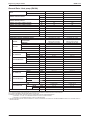
General Data - Heat pump (R22)
MODEL
INDOOR UNIT
OUTDOOR UNIT
Btu/h
NOMINAL COOLING CAPACITY
NOMINAL HEATING CAPACITY
MWM20JR
MWM25JR
MLC020CR
MLC025CR
19500
24000
W
5720
7030
Btu/h
19500
25000
W
5720
7330
NOMINAL TOTAL INPUT POWER (COOLING)
W
1850
2530
NOMINAL TOTAL INPUT POWER (HEATING)
W
1750
2465
NOMINAL RUNNING CURRENT (COOLING)
A
8.21
11.30
NOMINAL RUNNING CURRENT (HEATING)
A
7.73
11.01
V/Ph/Hz
220 - 240 / 1 / 50
220 - 240 / 1 / 50
EER
W/W
3.29
3.21
COP
W/W
3.67
3.62
POWER SOURCE
REFRIGERANT TYPE
REFRIGERANT CONTROL (EXPANSION DEVICE)
CONTROL
AIR DISCHARGE
OPERATION
INDOOR UNIT
AIR FLOW
PACKING DIMENSION
OUTDOOR UNIT
LCD REMOTE CONTROL
MEDIUM
l/s / CFM
225 / 478
253 / 537
LOW
l/s / CFM
200 / 424
223 / 474
dBA
42 / 39 / 36
43 / 39 / 37
HEIGHT
mm/in
310 / 12.2
310 / 12.2
WIDTH
mm/in
1065 / 41.9
1065 / 41.9
DEPTH
mm/in
224 / 8.8
224 / 8.8
HEIGHT
mm/in
370 / 14.6
370 / 14.6
WIDTH
mm/in
1121 / 44.1
1121 / 44.1
DEPTH
mm/in
285 / 11.2
285 / 11.2
kg/lb
14 / 30.8
14 / 30.8
mm/in
19.05 / 0.75
19.05 / 0.75
l/s / CFM
614 / 1300
755 / 1600
SOUND PRESSURE LEVEL
dBA
51
52
HEIGHT
mm/in
654 / 25.7
756 / 29.8
WIDTH
mm/in
855 / 33.7
855 / 33.7
DEPTH
mm/in
328 / 12.9
328 / 12.9
HEIGHT
mm/in
710 / 28.0
810 / 31.9
WIDTH
mm/in
990 / 39.0
990 / 39.0
DEPTH
mm/in
415 / 16.3
415 / 16.3
kg/lb
57 / 125.4
60 / 132.0
FLARE VALVE
FLARE VALVE
UNIT WEIGHT
TYPE
REFRIGERANT CHARGE
LCD REMOTE CONTROL
290 / 616
CONDENSATE DRAIN SIZE
PIPE CONNECTION
AUTO LOUVER (UP & DOWN) &
GRILLE (LEFT & RIGHT)
252 / 536
AIR FLOW
PACKING DIMENSION
AUTO LOUVER (UP & DOWN) &
GRILLE (LEFT & RIGHT)
l/s / CFM
UNIT WEIGHT
UNIT DIMENSION
R22
OUTDOOR CAP. TUBE
HIGH
SOUND PRESSURE LEVEL (H/M/L)
UNIT DIMENSION
R22
OUTDOOR CAP. TUBE
SIZE
LIQUID
mm/in
9.52 / 3/8
9.52 / 3/8
GAS
mm/in
15.87 / 5/8
15.87 / 5/8
kg/lb
1.63 / 3.59
1.72 / 3.78
1) ALL SPECIFICATIONS ARE SUBJECTED TO CHANGE BY THE MANUFACTURER WITHOUT PRIOR NOTICE.
2) ALL UNITS ARE BEING TESTED AND COMPLY TO ISO 5151.
3) NOMINAL COOLING AND HEATING CAPACITY ARE BASED ON THE CONDITIONS BELOW :
a) COOLING - 27°C DB / 19°C WB INDOOR AND 35°C DB / 24°C WB OUTDOOR
b) HEATING - 20°C DB INDOOR AND 7°C DB / 6°C WB OUTDOOR
4) SOUND PRESSURE LEVEL ARE ACCORDING TO JIS B 8615 STANDARD. POSITION OF THE MEASUREMENT POINT IS 1m IN FRONT AND 1m
BELOW THE UNIT.
31
MWM-J-2011
Engineering & Physical Data
General Data - Cooling Only (R410A)
MODEL
INDOOR UNIT
M5WM10J
M5WM15J
OUTDOOR UNIT
M5LC10C
M5LC15C
Btu/h
9040
10750
NOMINAL CAPACITY
W
2650
3150
NOMINAL TOTAL INPUT POWER
W
825
1094
NOMINAL RUNNING CURRENT
A
3.70
5.10
V/Ph/Hz
220 - 240 / 1 / 50
220 - 240 / 1 / 50
W/W
3.30
3.32
R410A
R410A
OUTDOOR CAP. TUBE
OUTDOOR CAP. TUBE
AUTO LOUVER (UP & DOWN) &
GRILLE (LEFT & RIGHT)
AUTO LOUVER (UP & DOWN) &
GRILLE (LEFT & RIGHT)
POWER SOURCE
EER
REFRIGERANT TYPE
REFRIGERANT CONTROL (EXPANSION DEVICE)
CONTROL
AIR DISCHARGE
OPERATION
INDOOR UNIT
AIR FLOW
LCD REMOTE CONTROL
LCD REMOTE CONTROL
HIGH
l/s / CFM
158 / 335
163 / 346
MEDIUM
l/s / CFM
132 / 279
138 / 293
LOW
l/s / CFM
105 / 222
113 / 240
dBA
38 / 32 / 27
38 / 34 / 29
HEIGHT
mm/in
288 / 11.3
288 / 11.3
WIDTH
mm/in
800 / 31.5
800 / 31.5
DEPTH
mm/in
204 / 8.0
204 / 8.0
HEIGHT
mm/in
350 / 13.8
350 / 13.8
WIDTH
mm/in
874 / 34.4
874 / 34.4
DEPTH
mm/in
280 / 11.0
280 / 11.0
kg/lb
12 / 26.5
12 / 26.5
mm/in
16 / 0.6
16 / 0.6
l/s / CFM
396 / 840
457 / 969
dBA
46
49
HEIGHT
mm/in
540 / 21.3
540 / 21.3
WIDTH
mm/in
700 / 27.6
700 / 27.6
SOUND PRESSURE LEVEL (H/M/L)
UNIT DIMENSION
PACKING DIMENSION
UNIT WEIGHT
CONDENSATE DRAIN SIZE
AIR FLOW
SOUND PRESSURE LEVEL
OUTDOOR UNIT
UNIT DIMENSION
PACKING DIMENSION
DEPTH
mm/in
250 / 9.8
250 / 9.8
HEIGHT
mm/in
620 / 24.4
620 / 24.4
WIDTH
mm/in
810 / 31.9
810 / 31.9
DEPTH
mm/in
330 / 13.0
330 / 13.0
kg/lb
34 / 75.0
34 / 75.0
FLARE VALVE
FLARE VALVE
6.4 / 1/4
6.4 / 1/4
UNIT WEIGHT
TYPE
PIPE CONNECTION
REFRIGERANT CHARGE
SIZE
LIQUID
mm/in
GAS
mm/in
9.5 / 3/8
12.7 / 1/2
kg/lb
0.80 / 1.76
0.89/1.96
1) ALL SPECIFICATIONS ARE SUBJECTED TO CHANGE BY THE MANUFACTURER WITHOUT PRIOR NOTICE.
2) ALL UNITS ARE BEING TESTED AND COMPLY TO ISO 5151.
3) NOMINAL COOLING AND HEATING CAPACITY ARE BASED ON THE CONDITIONS BELOW :
COOLING - 27°C DB / 19°C WB INDOOR AND 35°C DB / 24°C WB OUTDOOR
4) SOUND PRESSURE LEVEL ARE ACCORDING TO JIS B 8615 STANDARD. POSITION OF THE MEASUREMENT POINT IS 1m IN FRONT AND 1m
BELOW THE UNIT.
32
Engineering & Physical Data
MWM-J-2011
General Data - Heat pump (R410A)
MODEL
INDOOR UNIT
M5WM10JR
M5WM15JR
OUTDOOR UNIT
M5LC10CR
M5LC15CR
9040
10750
Btu/h
NOMINAL COOLING CAPACITY
NOMINAL HEATING CAPACITY
W
2650
3150
Btu/h
9550
11530
W
2800
3380
NOMINAL TOTAL INPUT POWER (COOLING)
W
825
1094
NOMINAL TOTAL INPUT POWER (HEATING)
W
775
988
NOMINAL RUNNING CURRENT (COOLING)
A
3.70
5.10
NOMINAL RUNNING CURRENT (HEATING)
A
3.20
4.70
220 - 240 / 1 / 50
POWER SOURCE
V/Ph/Hz
220 - 240 / 1 / 50
EER
W/W
3.33
3.35
COP
W/W
3.71
3.72
R410A
R410A
REFRIGERANT TYPE
REFRIGERANT CONTROL (EXPANSION DEVICE)
CONTROL
AIR DISCHARGE
OPERATION
INDOOR UNIT
AIR FLOW
OUTDOOR CAP. TUBE
AUTO LOUVER (UP & DOWN) &
GRILLE (LEFT & RIGHT)
LCD REMOTE CONTROL
LCD REMOTE CONTROL
HIGH
l/s / CFM
158 / 335
163 / 346
MEDIUM
l/s / CFM
132 / 279
138 / 293
LOW
l/s / CFM
105 / 222
113 / 240
38 / 34 / 29
SOUND PRESSURE LEVEL (H/M/L)
UNIT DIMENSION
PACKING DIMENSION
dBA
38 / 32 / 27
HEIGHT
mm/in
288 / 11.3
288 / 11.3
WIDTH
mm/in
800 / 31.5
800 / 31.5
DEPTH
mm/in
204 / 8.0
204 / 8.0
HEIGHT
mm/in
350 / 13.8
350 / 13.8
WIDTH
mm/in
874 / 34.4
874 / 34.4
DEPTH
mm/in
280 / 11.0
280 / 11.0
kg/lb
12 / 26.5
12 / 26.5
UNIT WEIGHT
CONDENSATE DRAIN SIZE
mm/in
16 / 0.6
16 / 0.6
l/s / CFM
396 / 840
457 / 969
dBA
46
49
HEIGHT
mm/in
540 / 21.3
540 / 21.3
WIDTH
mm/in
700 / 27.6
700 / 27.6
DEPTH
mm/in
250 / 9.8
250 / 9.8
HEIGHT
mm/in
620 / 24.4
620 / 24.4
WIDTH
mm/in
810 / 31.9
810 / 31.9
DEPTH
mm/in
330 / 13.0
330 / 13.0
kg/lb
34 / 75.0
34 / 75.0
FLARE VALVE
FLARE VALVE
AIR FLOW
SOUND PRESSURE LEVEL
UNIT DIMENSION
OUTDOOR UNIT
OUTDOOR CAP. TUBE
AUTO LOUVER (UP & DOWN) &
GRILLE (LEFT & RIGHT)
PACKING DIMENSION
UNIT WEIGHT
TYPE
PIPE CONNECTION
REFRIGERANT CHARGE
SIZE
LIQUID
mm/in
6.4 / 1/4
6.4 / 1/4
GAS
mm/in
9.5 / 3/8
12.7 / 1/2
kg/lb
0.80 / 1.76
0.89 / 1.96
1) ALL SPECIFICATIONS ARE SUBJECTED TO CHANGE BY THE MANUFACTURER WITHOUT PRIOR NOTICE.
2) ALL UNITS ARE BEING TESTED AND COMPLY TO ISO 5151.
3) NOMINAL COOLING AND HEATING CAPACITY ARE BASED ON THE CONDITIONS BELOW :
a) COOLING - 27°C DB / 19°C WB INDOOR AND 35°C DB / 24°C WB OUTDOOR
b) HEATING - 20°C DB INDOOR AND 7°C DB / 6°C WB OUTDOOR
4) SOUND PRESSURE LEVEL ARE ACCORDING TO JIS B 8615 STANDARD. POSITION OF THE MEASUREMENT POINT IS 1m IN FRONT AND 1m
BELOW THE UNIT.
33
MWM-J-2011
Engineering & Physical Data
Component Data - Cooling Only (R22)
MODEL
INDOOR UNIT
MWM09J
MWM15J
OUTDOOR UNIT
MLC09C
MLC15C
CROSS FLOW FAN
CROSS FLOW FAN
TYPE
INDOOR FAN
QUANTITY
1
1
MATERIAL
GLASS REINFORCED ACRYL
STYRENE RESIN
GLASS REINFORCED ACRYL
STYRENE RESIN
DIRECT
DIRECT
DRIVE
DIAMETER
mm/in
92 / 3.6
92 / 3.6
LENGTH
mm/in
607 / 23.9
607 / 23.9
INDUCTION
INDUCTION
TYPE
INDOOR FAN MOTOR
QUANTITY
INDEX OF PROTECTION (IP)
TYPE
OUTDOOR FAN
PROPELLER
PROPELLER
1
MATERIAL
GLASS REINFORCED ACRYL
STYRENE RESIN
GLASS REINFORCED ACRYL
STYRENE RESIN
DIRECT
DIRECT
mm/in
TYPE
QUANTITY
INDEX OF PROTECTION (IP)
TYPE
OIL TYPE
cm3 / fl.oz.
OIL AMOUNT
MATERIAL
TUBE
FIN
1
1
IP24
IP24
ROTARY
ROTARY
RB68A or FREOL ALPHA68M
RB68A or FREOL ALPHA68M
350 / 12.3
430 / 15.1
SEAMLESS INNER GROOVE
COPPER
SEAMLESS INNER GROOVE
COPPER
7.00 / 0.276
7.00 / 0.276
mm/in
0.28 / 0.011
0.28 / 0.011
ALUMINIUM (HYDROPHILIC FIN)
ALUMINIUM (HYDROPHILIC FIN)
THICKNESS
mm/in
0.11 / 0.004
0.11 / 0.004
FACE AREA
m2/ft2
0.18 / 1.930
0.18 / 1.930
2
2
MATERIAL
DIAMETER
mm/in
THICKNESS
mm/in
MATERIAL
FIN
INDUCTION
mm/in
FIN PER INCH
OUTDOOR COIL
406 / 16
INDUCTION
THICKNESS
ROW
TUBE
356 / 14
DIAMETER
MATERIAL
INDOOR COIL
18
18
SEAMLESS INNER GROOVE
COPPER
SEAMLESS INNER GROOVE
COPPER
7.00 / 0.276
7.00 / 0.276
0.24 / 0.009
0.24 / 0.009
ALUMINIUM (RAISE LANCE)
ALUMINIUM (RAISE LANCE)
THICKNESS
mm/in
0.10 / 0.004
0.10 / 0.004
FACE AREA
m /ft
0.31 / 3.400
0.36 / 3.940
2
2
ROW
1
1
FIN PER INCH
18
20
MILDEW PROOF PP FILTER
MILDEW PROOF PP FILTER
TYPE
QUANTITY
AIR QUALITY
IP44
1
DIAMETER
COMPRESSOR
1
IP44
QUANTITY
DRIVE
OUTDOOR FAN
MOTOR
1
FILTER
SIZE
INDOOR UNIT
CASING
OUTDOOR UNIT
pc
2
2
LENGTH
mm/in
302 / 11.9
302 / 11.9
WIDTH
mm/in
280 / 11.0
280 / 11.0
THICKNESS
mm/in
2.0 / 0.1
2.0 / 0.1
MATERIAL
HIGH IMPACT POLYSTYRENE
HIGH IMPACT POLYSTYRENE
FINISHING
MAT
MAT
COLOUR
WHITE
WHITE
MATERIAL
GALVANISED MILD STEEL
GALVANISED MILD STEEL
FINISHING
POLYESTER POWDER
POLYESTER POWDER
COLOUR
LIGHT GREY
LIGHT GREY
1) ALL SPECIFICATIONS ARE SUBJECTED TO CHANGE BY THE MANUFACTURER WITHOUT PRIOR NOTICE.
34
Engineering & Physical Data
MWM-J-2011
Component Data - Cooling Only (R22)
MODEL
INDOOR UNIT
MWM20J
OUTDOOR UNIT
MLC020C
MLC025C
CROSS FLOW FAN
CROSS FLOW FAN
QUANTITY
1
1
MATERIAL
GLASS REINFORCED ACRYL
STYRENE RESIN
GLASS REINFORCED ACRYL
STYRENE RESIN
TYPE
INDOOR FAN
DRIVE
DIAMETER
mm/in
LENGTH
mm/in
TYPE
INDOOR FAN MOTOR
QUANTITY
INDEX OF PROTECTION (IP)
867 / 34.13
INDUCTION
1
1
IP44
QUANTITY
1
1
MATERIAL
GLASS REINFORCED ACRYL
STYRENE RESIN
GLASS REINFORCED ACRYL
STYRENE RESIN
mm/in
TYPE
QUANTITY
INDEX OF PROTECTION (IP)
TYPE
OIL TYPE
cm3 / fl.oz.
OIL AMOUNT
MATERIAL
TUBE
FIN
FIN
INDUCTION
INDUCTION
1
1
IP54
IP54
ROTARY HERMETIC
ROTARY HERMETIC
ATMOS NM56M or SUNISO 4GDID
ATMOS NM56M or SUNISO 4GDID
1000 / 35.2
700 / 24.6
SEAMLESS INNER GROOVE
COPPER
SEAMLESS INNER GROOVE
COPPER
mm/in
7.00 / 0.276
7.00 / 0.276
mm/in
0.24 / 0.009
0.28 / 0.011
ALUMINIUM (HYDROPHILIC FIN)
ALUMINIUM (HYDROPHILIC FIN)
THICKNESS
mm/in
0.105 / 0.0041
0.11 / 0.004
FACE AREA
m2/ft2
0.29 / 3.100
0.18 / 1.930
ROW
2
2
FIN PER INCH
18
18
SEAMLESS INNER GROOVE
COPPER
SEAMLESS INNER GROOVE
COPPER
7.00 / 0.276
DIAMETER
mm/in
7.00 / 0.276
THICKNESS
mm/in
0.28 / 0.011
0.28 / 0.011
ALUMINIUM (RAISE LANCE)
ALUMINIUM (RAISE LANCE)
MATERIAL
OUTDOOR COIL
DIRECT
457.2 / 18
THICKNESS
MATERIAL
TUBE
DIRECT
457.2 / 18
DIAMETER
MATERIAL
INDOOR COIL
THICKNESS
mm/in
0.11 / 0.0043
0.127 / 0.005
FACE AREA
m2/ft2
0.52 / 5.59
0.61 / 6.52
2
2
ROW
FIN PER INCH
18
18
SARANET
SARANET
pc
2
2
LENGTH
mm/in
421 / 16.57
421 / 16.57
WIDTH
mm/in
306 / 12.05
306 / 12.05
THICKNESS
mm/in
2 / 0.08
2 / 0.08
MATERIAL
HIGH IMPACT POLYSTYRENE
HIGH IMPACT POLYSTYRENE
FINISHING
MAT
MAT
COLOUR
WHITE
WHITE
MATERIAL
GALVANISED MILD STEEL
GALVANISED MILD STEEL
FINISHING
POLYESTER POWDER
POLYESTER POWDER
COLOUR
LIGHT GREY
LIGHT GREY
TYPE
QUANTITY
AIR QUALITY
867 / 34.13
INDUCTION
PROPELLER
DIAMETER
COMPRESSOR
DIRECT
102 / 4.02
IP44
DRIVE
OUTDOOR FAN
MOTOR
DIRECT
102 / 4.02
PROPELLER
TYPE
OUTDOOR FAN
FILTER
SIZE
INDOOR UNIT
CASING
OUTDOOR UNIT
1) ALL SPECIFICATIONS ARE SUBJECTED TO CHANGE BY THE MANUFACTURER WITHOUT PRIOR NOTICE.
35
MWM25J
MWM-J-2011
Engineering & Physical Data
Component Data - Heat Pump (R22)
MODEL
INDOOR UNIT
MWM09JR
OUTDOOR UNIT
MLC09CR
MLC15CR
CROSS FLOW FAN
CROSS FLOW FAN
TYPE
QUANTITY
1
1
MATERIAL
GLASS REINFORCED ACRYL
STYRENE RESIN
GLASS REINFORCED ACRYL
STYRENE RESIN
DIRECT
DIRECT
INDOOR FAN
DRIVE
DIAMETER
mm/in
92 / 3.6
92 / 3.6
LENGTH
mm/in
607 / 23.9
607 / 23.9
INDUCTION
INDUCTION
1
1
TYPE
INDOOR FAN MOTOR
QUANTITY
INDEX OF PROTECTION (IP)
TYPE
OUTDOOR FAN
1
1
GLASS REINFORCED ACRYL
STYRENE RESIN
GLASS REINFORCED ACRYL
STYRENE RESIN
DIRECT
DIRECT
mm/in
TYPE
QUANTITY
INDEX OF PROTECTION (IP)
TYPE
OIL TYPE
OIL AMOUNT
cm3 / fl.oz.
MATERIAL
TUBE
DIAMETER
mm/in
THICKNESS
mm/in
MATERIAL
INDOOR COIL
FIN
TUBE
FIN
406 / 16
INDUCTION
INDUCTION
1
1
IP24
IP24
ROTARY
ROTARY
RB68A or FREOL ALPHA68M
RB68A or FREOL ALPHA68M
350 / 12.3
430 / 15.1
SEAMLESS INNER GROOVE
COPPER
SEAMLESS INNER GROOVE
COPPER
7.00 / 0.276
7.00 / 0.276
0.28 / 0.011
0.28 / 0.011
ALUMINIUM (HYDROPHILIC FIN)
ALUMINIUM (HYDROPHILIC FIN)
mm/in
0.11 / 0.004
0.11 / 0.004
FACE AREA
m /ft
0.18 / 1.930
0.18 / 1.930
2
2
ROW
2
2
FIN PER INCH
18
18
SEAMLESS INNER GROOVE
COPPER
SEAMLESS INNER GROOVE
COPPER
DIAMETER
mm/in
7.00 / 0.276
9.52 / 3/8
THICKNESS
mm/in
0.24 / 0.009
0.28 / 0.011
ALUMINIUM (RAISE LANCE)
ALUMINIUM (HYDROPHILIC FIN)
MATERIAL
OUTDOOR COIL
356 / 14
THICKNESS
MATERIAL
THICKNESS
mm/in
0.10 / 0.004
0.11 / 0.004
FACE AREA
m 2/ft2
0.31 / 3.400
0.36 / 3.940
ROW
1
1
FIN PER INCH
18
18
MILDEW PROOF PP FILTER
MILDEW PROOF PP FILTER
TYPE
QUANTITY
AIR QUALITY
IP44
PROPELLER
QUANTITY
DIAMETER
COMPRESSOR
IP44
PROPELLER
MATERIAL
DRIVE
OUTDOOR FAN
MOTOR
MWM15JR
FILTER
SIZE
INDOOR UNIT
CASING
OUTDOOR UNIT
pc
2
2
LENGTH
mm/in
302 / 11.9
302 / 11.9
WIDTH
mm/in
280 / 11.0
280 / 11.0
THICKNESS
mm/in
2.0 / 0.1
2.0 / 0.1
MATERIAL
HIGH IMPACT POLYSTYRENE
HIGH IMPACT POLYSTYRENE
FINISHING
MAT
MAT
COLOUR
WHITE
WHITE
MATERIAL
GALVANISED MILD STEEL
GALVANISED MILD STEEL
FINISHING
POLYESTER POWDER
POLYESTER POWDER
COLOUR
LIGHT GREY
LIGHT GREY
1) ALL SPECIFICATIONS ARE SUBJECTED TO CHANGE BY THE MANUFACTURER WITHOUT PRIOR NOTICE.
36
Engineering & Physical Data
MWM-J-2011
Component Data - Heat Pump (R22)
MODEL
INDOOR UNIT
MWM20JR
OUTDOOR UNIT
MLC020CR
MLC025CR
CROSS FLOW FAN
CROSS FLOW FAN
QUANTITY
1
1
MATERIAL
GLASS REINFORCED ACRYL
STYRENE RESIN
GLASS REINFORCED ACRYL
STYRENE RESIN
TYPE
INDOOR FAN
DRIVE
DIRECT
DIRECT
DIAMETER
mm/in
102 / 4.02
102 / 4.02
LENGTH
mm/in
867 / 34.13
867 / 34.13
INDUCTION
INDUCTION
TYPE
INDOOR FAN MOTOR
QUANTITY
INDEX OF PROTECTION (IP)
TYPE
OUTDOOR FAN
IP44
PROPELLER
PROPELLER
1
MATERIAL
GLASS REINFORCED ACRYL
STYRENE RESIN
GLASS REINFORCED ACRYL
STYRENE RESIN
DIRECT
DIRECT
mm/in
TYPE
QUANTITY
INDEX OF PROTECTION (IP)
TYPE
OIL TYPE
cm3 / fl.oz.
OIL AMOUNT
MATERIAL
TUBE
FIN
1
IP54
IP54
ROTARY HERMETIC
ROTARY HERMETIC
ATMOS NM56M or SUNISO 4GDID
ATMOS NM56M or SUNISO 4GDID
1000 / 35.2
700 / 24.6
SEAMLESS INNER GROOVE
COPPER
SEAMLESS INNER GROOVE
COPPER
mm/in
7.00 / 0.276
7.00 / 0.276
0.24 / 0.009
0.28 / 0.011
ALUMINIUM (HYDROPHILIC FIN)
ALUMINIUM (HYDROPHILIC FIN)
THICKNESS
mm/in
0.105 / 0.0041
0.11 / 0.004
FACE AREA
m2/ft2
0.29 / 3.100
0.18 / 1.930
2
2
MATERIAL
DIAMETER
mm/in
THICKNESS
mm/in
MATERIAL
FIN
1
mm/in
FIN PER INCH
OUTDOOR COIL
457.2 / 18
INDUCTION
THICKNESS
ROW
TUBE
457.2 / 18
INDUCTION
DIAMETER
MATERIAL
INDOOR COIL
18
18
SEAMLESS INNER GROOVE
COPPER
SEAMLESS INNER GROOVE
COPPER
7.00 / 0.276
7.00 / 0.276
0.28 / 0.011
0.28 / 0.011
ALUMINIUM (RAISE LANCE)
ALUMINIUM (RAISE LANCE)
THICKNESS
mm/in
0.11 / 0.0043
0.11 / 0.0043
FACE AREA
m2/ft2
0.52 / 5.59
0.61 / 6.52
ROW
2
2
FIN PER INCH
18
18
SARANET
SARANET
TYPE
QUANTITY
AIR QUALITY
1
IP44
1
DIAMETER
COMPRESSOR
1
QUANTITY
DRIVE
OUTDOOR FAN
MOTOR
FILTER
SIZE
INDOOR UNIT
CASING
OUTDOOR UNIT
pc
2
2
LENGTH
mm/in
421 / 16.57
421 / 16.57
WIDTH
mm/in
306 / 12.05
306 / 12.05
THICKNESS
mm/in
2 / 0.08
2 / 0.08
MATERIAL
HIGH IMPACT POLYSTYRENE
HIGH IMPACT POLYSTYRENE
FINISHING
MAT
MAT
COLOUR
WHITE
WHITE
MATERIAL
GALVANISED MILD STEEL
GALVANISED MILD STEEL
FINISHING
POLYESTER POWDER
POLYESTER POWDER
COLOUR
LIGHT GREY
LIGHT GREY
1) ALL SPECIFICATIONS ARE SUBJECTED TO CHANGE BY THE MANUFACTURER WITHOUT PRIOR NOTICE.
37
MWM25JR
MWM-J-2011
Engineering & Physical Data
Component Data - Cooling Only (R410A)
MODEL
INDOOR UNIT
M5WM10J
OUTDOOR UNIT
M5LC10C
M5LC15C
CROSS FLOW FAN
CROSS FLOW FAN
TYPE
QUANTITY
1
1
MATERIAL
GLASS REINFORCED ACRYL
STYRENE RESIN
GLASS REINFORCED ACRYL
STYRENE RESIN
DIRECT
DIRECT
INDOOR FAN
DRIVE
DIAMETER
mm/in
92 / 3.6
92 / 3.6
LENGTH
mm/in
607 / 23.9
607 / 23.9
INDUCTION
INDUCTION
1
1
TYPE
INDOOR FAN MOTOR
QUANTITY
INDEX OF PROTECTION (IP)
IP44
IP44
PROPELLER
PROPELLER
QUANTITY
1
1
MATERIAL
GLASS REINFORCED ACRYL
STYRENE RESIN
GLASS REINFORCED ACRYL
STYRENE RESIN
DIRECT
DIRECT
406 / 16
406 / 16
INDUCTION
INDUCTION
TYPE
OUTDOOR FAN
DRIVE
DIAMETER
mm/in
TYPE
OUTDOOR FAN
MOTOR
QUANTITY
INDEX OF PROTECTION (IP)
TYPE
COMPRESSOR
OIL TYPE
OIL AMOUNT
cm3 / fl.oz.
MATERIAL
TUBE
FIN
ROTARY
ROTARY
RB68A or FREOL ALPHA68M
RB68A or FREOL ALPHA68M
350 / 12.3
430 / 15.1
SEAMLESS INNER GROOVE
COPPER
SEAMLESS INNER GROOVE
COPPER
7.00 / 0.276
7.00 / 0.276
mm/in
0.28 / 0.011
0.28 / 0.011
ALUMINIUM (HYDROPHILIC FIN)
ALUMINIUM (HYDROPHILIC FIN)
THICKNESS
mm/in
0.11 / 0.004
0.11 / 0.004
FACE AREA
m2/ft2
0.18 / 1.930
0.18 / 1.930
2
2
MATERIAL
DIAMETER
mm/in
THICKNESS
mm/in
MATERIAL
FIN
IP24
mm/in
FIN PER INCH
OUTDOOR COIL
1
IP24
THICKNESS
ROW
TUBE
1
DIAMETER
MATERIAL
INDOOR COIL
18
18
SEAMLESS INNER GROOVE
COPPER
SEAMLESS INNER GROOVE
COPPER
7.00 / 0.276
9.52 / 3/8
0.28 / 0.011
0.33 / 0.013
ALUMINIUM (RAISE LANCE)
ALUMINIUM (SLIT FIN)
THICKNESS
mm/in
0.10 / 0.004
0.11 / 0.004
FACE AREA
m2/ft2
0.36 / 3.940
0.36 / 3.940
1
1
ROW
FIN PER INCH
20
18
MILDEW PROOF PP FILTER
MILDEW PROOF PP FILTER
pc
2
2
LENGTH
mm/in
302 / 11.9
302 / 11.9
WIDTH
mm/in
280 / 11.0
280 / 11.0
THICKNESS
mm/in
2.0 / 0.1
2.0 / 0.1
MATERIAL
HIGH IMPACT POLYSTYRENE
HIGH IMPACT POLYSTYRENE
FINISHING
MAT
MAT
COLOUR
WHITE
WHITE
MATERIAL
GALVANISED MILD STEEL
GALVANISED MILD STEEL
FINISHING
POLYESTER POWDER
POLYESTER POWDER
COLOUR
LIGHT GREY
LIGHT GREY
TYPE
QUANTITY
AIR QUALITY
M5WM15J
FILTER
SIZE
INDOOR UNIT
CASING
OUTDOOR UNIT
1) ALL SPECIFICATIONS ARE SUBJECTED TO CHANGE BY THE MANUFACTURER WITHOUT PRIOR NOTICE.
38
Engineering & Physical Data
MWM-J-2011
Component Data - Heat Pump (R410A)
MODEL
INDOOR UNIT
M5WM10JR
OUTDOOR UNIT
M5LC10CR
M5LC15CR
CROSS FLOW FAN
CROSS FLOW FAN
TYPE
QUANTITY
1
1
MATERIAL
GLASS REINFORCED ACRYL
STYRENE RESIN
GLASS REINFORCED ACRYL
STYRENE RESIN
DIRECT
DIRECT
INDOOR FAN
DRIVE
DIAMETER
mm/in
92 / 3.6
92 / 3.6
LENGTH
mm/in
607 / 23.9
607 / 23.9
INDUCTION
INDUCTION
1
1
TYPE
INDOOR FAN MOTOR
QUANTITY
INDEX OF PROTECTION (IP)
IP44
IP44
PROPELLER
PROPELLER
QUANTITY
1
1
MATERIAL
GLASS REINFORCED ACRYL
STYRENE RESIN
GLASS REINFORCED ACRYL
STYRENE RESIN
DIRECT
DIRECT
406 / 16
406 / 16
INDUCTION
INDUCTION
TYPE
OUTDOOR FAN
DRIVE
DIAMETER
mm/in
TYPE
OUTDOOR FAN
MOTOR
QUANTITY
INDEX OF PROTECTION (IP)
TYPE
COMPRESSOR
OIL TYPE
OIL AMOUNT
cm3 / fl.oz.
MATERIAL
TUBE
FIN
ROTARY
ROTARY
RB68A or FREOL ALPHA68M
RB68A or FREOL ALPHA68M
350 / 12.3
430 / 15.1
SEAMLESS INNER GROOVE
COPPER
SEAMLESS INNER GROOVE
COPPER
7.00 / 0.276
7.00 / 0.276
mm/in
0.28 / 0.011
0.28 / 0.011
ALUMINIUM (HYDROPHILIC FIN)
ALUMINIUM (HYDROPHILIC FIN)
THICKNESS
mm/in
0.11 / 0.004
0.11 / 0.004
FACE AREA
m2/ft2
0.18 / 1.930
0.18 / 1.930
2
2
MATERIAL
DIAMETER
mm/in
THICKNESS
mm/in
MATERIAL
FIN
IP24
mm/in
FIN PER INCH
OUTDOOR COIL
1
IP24
THICKNESS
ROW
TUBE
1
DIAMETER
MATERIAL
INDOOR COIL
18
18
SEAMLESS INNER GROOVE
COPPER
SEAMLESS INNER GROOVE
COPPER
7.00 / 0.276
9.52 / 3/8
0.28 / 0.011
0.33 / 0.013
ALUMINIUM (RAISE LANCE)
ALUMINIUM (HYDROPHILIC FIN)
THICKNESS
mm/in
0.10 / 0.004
0.11 / 0.004
FACE AREA
m2/ft2
0.36 / 3.940
0.36 / 3.940
1
1
ROW
FIN PER INCH
20
18
MILDEW PROOF PP FILTER
MILDEW PROOF PP FILTER
pc
2
2
LENGTH
mm/in
302 / 11.9
302 / 11.9
WIDTH
mm/in
280 / 11.0
280 / 11.0
THICKNESS
mm/in
2.0 / 0.1
2.0 / 0.1
MATERIAL
HIGH IMPACT POLYSTYRENE
HIGH IMPACT POLYSTYRENE
FINISHING
MAT
MAT
COLOUR
WHITE
WHITE
MATERIAL
GALVANISED MILD STEEL
GALVANISED MILD STEEL
FINISHING
POLYESTER POWDER
POLYESTER POWDER
COLOUR
LIGHT GREY
LIGHT GREY
TYPE
QUANTITY
AIR QUALITY
FILTER
SIZE
INDOOR UNIT
CASING
OUTDOOR UNIT
1) ALL SPECIFICATIONS ARE SUBJECTED TO CHANGE BY THE MANUFACTURER WITHOUT PRIOR NOTICE.
39
M5WM15JR
MWM-J-2011
Performance Data
Performance Data
Calculation Steps
Interpolation method can be used to get the total capacity, TC and sensible capacity, SC and power input, PI
at those temperatures which are not stated out in the table. Extrapolation method are not allowed to be used
to get the TC, SC and PI
Example:
Model: MWM09J - MLC09C
Indoor Condition: 25°C DB, 17°C WB
Outdoor Condition: 37°C DB
Fan speed: High
Solution:
Overall
Based on the Performance table:
1. Refer to the Indoor DB column,
- 25°C is located between 24°C and 27°C for 16oCWB (Thus, Interpolation need to be applied)
- 25°C is located between 24°C and 27°C for 19oCWB (Thus, Interpolation need to be applied)
2. Refer to the Indoor WB column,
- 17°C is located between 16°CWB and 19°CWB for 25oCDB (Thus, Interpolation need to be applied)
3. Refer to the Outdoor DB column,
- 37°C is located between 35°C and 40°C. (Thus, Interpolation need to be applied)
Please follow the steps below in order to get the required capacity.
1st Step
Extrapolation of Indoor WB
2nd Step
Interpolation of Indoor DB
3rd Step
Interpolation of Outdoor DB
Find TC, SC, PI for
(a) Indoor: 25°C DB, 16°C WB
Outdoor: 35°C DB
(b) Indoor: 25°C DB, 19°C WB
Outdoor: 35°C DB
Find TC, SC, PI for
(a) Indoor: 25°C DB, 17°C WB
Outdoor: 35°C DB
Find TC, SC, PI for
(a) Indoor: 25°C DB, 17°C WB
Outdoor: 37°C DB
(b) Indoor: 25°C DB, 17°C WB
Outdoor: 40°C DB
(c) Indoor: 25°C DB, 16°C WB
Outdoor: 40°C DB
(d) Indoor: 25°C DB, 19°C WB
Outdoor: 40°C DB
40
Performance Data
MWM-J-2011
Details:
1st Step:
To obtain the Total capacity, Sensible capacity and Power input for
(a) Indoor Condition: 25°C DB, 16°C WB
Outdoor Condition: 35°C DB
Outdoor DB, ˚C
Indoor DB˚C
Indoor WB˚C
35
24
16
25
...........................................
27
Total capacity, TC
Interpolation Method:
⇒
25º C – 24º C
27º C – 24º C
=
x1 – 10.85kW
11.03kW – 10.85kW
⇒ x1 = 10.91kW
Sensible capacity, SHC
Interpolation Method:
⇒
25º C – 24º C
27º C – 24º C
=
y1 – 10.39kW
11.03kW – 10.39kW
⇒ y1 = 10.60kW
Power Input, PI
Interpolation Method:
⇒
25º C – 24º C
27º C – 24º C
⇒ z1 = 4.00kW
41
=
z1 – 4.00kW
4.01kW – 4.00kW
TC (kW)
SHC (kW)
PI (kW)
10.85
10.39
x1
y1
4.00
z1
11.03
11.03
4.01
MWM-J-2011
Performance Data
(b) Indoor Condition: 25°C DB, 16°C WB
Outdoor Condition: 40°C DB
Outdoor DB, ˚C
Indoor DB˚C
Indoor WB˚C
40
24
16
25
...........................................
27
TC (kW)
SHC (kW)
PI (kW)
10.42
10.23
x2
y2
4.36
z2
10.66
10.66
4.38
Total capacity, TC
Interpolation Method:
⇒
25º C – 24º C
27º C – 24º C
=
x2 – 10.42kW
11.66kW – 10.42kW
⇒ x1 = 10.50kW
Sensible capacity, SHC
Interpolation Method:
⇒
25º C – 24º C
27º C – 24º C
=
y2 – 10.23kW
10.66kW – 10.23kW
⇒ y2 = 10.37kW
Power Input, PI
Interpolation Method:
⇒
25º C – 24º C
27º C – 24º C
=
z2 – 4.36kW
4.38kW – 4.36kW
⇒ z2 = 4.37kW
* Repeat process (a) and (b) in 1st step for the condition below:
(c) Indoor Condition: 25°C DB, 19°C WB
Outdoor Condition: 35°C DB
⇒ x3= 11.65kW
⇒ y3= 8.94kW
⇒ z3= 4.08kW
(d) Indoor Condition: 25°C DB, 19°C WB
Outdoor Condition: 40°C DB
⇒ x4= 11.36kW
⇒ y4= 9.03kW
⇒ z4= 4.43kW
42
Performance Data
MWM-J-2011
2nd Step:
To obtain the Total capacity, Sensible capacity and Power input for
(a) Indoor Condition: 25°C DB, 17°C WB
Outdoor Condition: 35°C DB
Outdoor DB, ˚C
Indoor DB˚C
Indoor WB˚C
35
17
25
...........................................
19
Total capacity, TC
Interpolation Method:
⇒
17º C – 16º C
19º C – 16º C
=
x5 – 10.91kW
11.65kW – 10.91kW
⇒ x5 = 11.16kW
Sensible capacity, SHC
Interpolation Method:
⇒
17º C – 16º C
19º C – 16º C
=
y5 – 10.60kW
8.94kW – 10.60kW
⇒ y5 = 10.05kW
Power Input, PI
Interpolation Method:
⇒
17º C – 16º C
19º C – 16º C
⇒ z5 = 4.03kW
43
=
z5 – 4.00kW
4.08kW – 4.00kW
PI (kW)
........
16
SHC (kW)
........
TC (kW)
10.91
x5
10.60
y5
4.00
z5
11.65
8.94
4.08
MWM-J-2011
Performance Data
(b) Indoor Condition: 25°C DB, 17°C WB
Outdoor Condition: 40°C DB
Outdoor DB, ˚C
Indoor DB˚C
Indoor WB˚C
40
17
25
...........................................
18
PI (kW)
........
16
SHC (kW)
........
TC (kW)
10.50
x6
10.37
y6
4.37
z6
11.36
9.03
4.43
Total capacity, TC
Interpolation Method:
⇒
17º C – 16º C
19º C – 16º C
=
x6 – 10.50kW
11.36kW – 10.50kW
⇒ x6 = 10.79kW
Sensible capacity, SHC
Interpolation Method:
⇒
17º C – 16º C
19º C – 16º C
=
y6 – 10.37kW
9.03kW – 10.37kW
⇒ y5 = 10.05kW
Power Input, PI
Interpolation Method:
⇒
17º C – 16º C
19º C – 16º C
=
z6 – 4.37kW
4.43kW – 4.37kW
⇒ z6 = 4.39kW
44
Performance Data
MWM-J-2011
3rd Step:
To obtain the Total capacity and Sensible capacity for
(a) Indoor Condition: 25°C DB, 17°C WB
Outdoor Condition: 37°C DB
Outdoor DB, ˚C
Indoor
DB˚C
Indoor
WB˚C
23
15
35
TC
(kW)
......................
PI
(kW)
TC
(kW)
SHC
(kW)
PI
(kW)
TC
(kW)
SHC
(kW)
PI
(kW)
11.16 10.05
4.03
x
y
z
10.79
9.92
4.39
Interpolation Method:
37º C – 35º C
40º C – 35º C
=
x – 11.16kW
10.79kW – 11.16kW
⇒ x = 11.01kW
Sensible capacity, SHC
Interpolation Method:
⇒
37º C – 35º C
40º C – 35º C
=
y – 10.05kW
9.92kW – 10.05kW
⇒ y = 9.99kW
Power Input, PI
Interpolation Method:
⇒
37º C – 35º C
40º C – 35º C
⇒ z = 4.17kW
45
=
40
SHC
(kW)
Total capacity, TC
⇒
37
z – 4.03kW
4.39kW – 4.03kW
MWM-J-2011
Performance Data
Cooling Only (R22)
Model: MWM09J - MLC09C
Cooling Mode
Outdoor temperature
AFR
EWB
(CFM)
EDB
19°C
TC
16°C
222
19°C
22°C
16°C
279
19°C
22°C
16°C
335
19°C
22°C
SHC
25°C
PI
TC
SHC
30°C
PI
TC
SHC
35°C
PI
TC
SHC
40°C
PI
TC
SHC
46°C
PI
TC
SHC
PI
21°C
2.32 1.82 0.70 2.24 1.77 0.76 2.16 1.72 0.82 2.07 1.67 0.89 1.90 1.56 0.97 1.75 1.46 1.07
24°C
2.32 2.17 0.70 2.24 2.13 0.76 2.16 2.08 0.82 2.07 2.02 0.89 1.90 1.89 0.97 1.76 1.76 1.07
27°C
2.34 2.34 0.70 2.26 2.26 0.76 2.18 2.18 0.83 2.10 2.10 0.90 1.94 1.94 0.97 1.80 1.80 1.07
30°C
2.41 2.41 0.71 2.34 2.34 0.77 2.27 2.27 0.83 2.20 2.20 0.90 2.04 2.04 0.98 1.91 1.91 1.08
24°C
2.56 1.70 0.71 2.47 1.65 0.77 2.38 1.61 0.84 2.29 1.56 0.91 2.10 1.46 0.99 1.94 1.37 1.09
27°C
2.56 1.94 0.71 2.47 1.90 0.77 2.38 1.85 0.84 2.29 1.81 0.91 2.10 1.69 0.99 1.94 1.60 1.09
30°C
2.57 2.39 0.71 2.48 2.34 0.77 2.39 2.29 0.84 2.30 2.24 0.91 2.12 2.09 0.99 1.96 1.96 1.09
33°C
2.60 2.60 0.72 2.51 2.51 0.78 2.43 2.43 0.84 2.35 2.35 0.91 2.17 2.17 0.99 2.03 2.03 1.10
27°C
2.82 1.66 0.73 2.72 1.62 0.79 2.62 1.58 0.85 2.52 1.54 0.93 2.31 1.43 1.01 2.14 1.35 1.11
30°C
2.82 2.02 0.73 2.72 1.98 0.79 2.62 1.93 0.85 2.52 1.89 0.93 2.32 1.77 1.01 2.14 1.68 1.11
33°C
2.82 2.36 0.73 2.72 2.32 0.79 2.62 2.27 0.85 2.52 2.22 0.93 2.32 2.09 1.01 2.15 1.98 1.11
36°C
2.83 2.68 0.73 2.73 2.62 0.79 2.64 2.57 0.86 2.54 2.51 0.93 2.35 2.35 1.01 2.18 2.18 1.11
21°C
2.42 1.89 0.71 2.33 1.85 0.77 2.24 1.80 0.83 2.15 1.75 0.90 1.97 1.63 0.98 1.82 1.53 1.08
24°C
2.42 2.30 0.71 2.34 2.25 0.77 2.25 2.19 0.83 2.16 2.14 0.90 1.98 1.98 0.98 1.83 1.83 1.08
27°C
2.45 2.45 0.71 2.37 2.37 0.77 2.29 2.29 0.83 2.21 2.21 0.91 2.04 2.04 0.98 1.90 1.90 1.09
30°C
2.55 2.55 0.72 2.48 2.48 0.78 2.40 2.40 0.84 2.33 2.33 0.91 2.16 2.16 0.99 2.01 2.01 1.10
24°C
2.66 1.79 0.72 2.57 1.75 0.78 2.47 1.70 0.85 2.37 1.66 0.92 2.18 1.54 1.00 2.01 1.45 1.10
27°C
2.67 2.06 0.72 2.57 2.02 0.78 2.47 1.97 0.85 2.37 1.93 0.92 2.18 1.80 1.00 2.02 1.71 1.10
30°C
2.68 2.55 0.72 2.58 2.49 0.78 2.49 2.44 0.85 2.40 2.38 0.92 2.21 2.21 1.00 2.05 2.05 1.10
33°C
2.72 2.72 0.72 2.64 2.64 0.79 2.56 2.56 0.85 2.47 2.47 0.93 2.29 2.29 1.01 2.14 2.14 1.11
27°C
2.92 1.76 0.73 2.82 1.71 0.80 2.72 1.67 0.86 2.61 1.63 0.94 2.40 1.52 1.01 2.22 1.43 1.12
30°C
2.93 2.15 0.73 2.82 2.11 0.80 2.72 2.06 0.86 2.61 2.01 0.94 2.40 1.89 1.02 2.22 1.79 1.12
33°C
2.93 2.52 0.74 2.83 2.48 0.80 2.73 2.43 0.86 2.62 2.37 0.94 2.41 2.23 1.02 2.23 2.11 1.12
36°C
2.95 2.85 0.74 2.86 2.80 0.80 2.76 2.74 0.87 2.66 2.66 0.94 2.45 2.45 1.02 2.28 2.28 1.13
21°C
2.50 1.98 0.72 2.41 1.93 0.77 2.32 1.88 0.84 2.22 1.82 0.91 2.04 1.70 0.99 1.88 1.60 1.09
24°C
2.52 2.40 0.72 2.43 2.35 0.77 2.34 2.29 0.84 2.24 2.23 0.91 2.06 2.06 0.99 1.90 1.90 1.09
27°C
2.56 2.56 0.72 2.47 2.47 0.78 2.39 2.39 0.84 2.31 2.31 0.91 2.13 2.13 0.99 1.99 1.99 1.10
30°C
2.69 2.69 0.72 2.61 2.61 0.79 2.53 2.53 0.85 2.44 2.44 0.92 2.26 2.26 1.00 2.11 2.11 1.11
24°C
2.76 1.90 0.73 2.66 1.85 0.79 2.56 1.80 0.85 2.45 1.75 0.93 2.25 1.63 1.00 2.08 1.54 1.11
27°C
2.76 2.19 0.73 2.67 2.14 0.79 2.57 2.09 0.85 2.46 2.04 0.93 2.26 1.91 1.00 2.09 1.81 1.11
30°C
2.79 2.70 0.73 2.69 2.64 0.79 2.59 2.58 0.86 2.49 2.49 0.93 2.30 2.30 1.01 2.13 2.13 1.11
33°C
2.85 2.85 0.73 2.76 2.76 0.79 2.68 2.68 0.86 2.59 2.59 0.94 2.40 2.40 1.02 2.25 2.25 1.12
27°C
3.03 1.86 0.74 2.92 1.82 0.80 2.81 1.77 0.87 2.69 1.72 0.94 2.48 1.61 1.02 2.29 1.52 1.13
30°C
3.03 2.29 0.74 2.92 2.24 0.80 2.81 2.20 0.87 2.70 2.15 0.94 2.48 2.01 1.02 2.29 1.90 1.13
33°C
3.04 2.68 0.74 2.94 2.63 0.80 2.83 2.58 0.87 2.72 2.52 0.95 2.50 2.36 1.03 2.32 2.24 1.13
36°C
3.07 3.03 0.74 2.97 2.97 0.81 2.87 2.87 0.87 2.77 2.77 0.95 2.56 2.56 1.03 2.38 2.38 1.14
Remark:
AFR: Air flow rate (CFM)
EWB: Entering Wet Bulb Temp. (°C)
EDB: Entering Dry Bulb Temp. (°C)
TC: Total Cooling Capacity (kW)
SHC: Sensible Heat Capacity (kW)
PI: Power Input
Notes:
1. Ratings shown are gross capacities which do not include a deduction for indoor fan motor heat.
2.
shows nominal capacities.
3. Direct interpolation is permissible. Do not extrapolate.
4. Unit is able to operate at ambient from 0 °C to 46°C without pressure trip.
46
Performance Data
MWM-J-2011
Model: MWM15J - MLC15C
Cooling Mode
Outdoor temperature
AFR
EWB
(CFM)
EDB
19°C
TC
16°C
240
19°C
22°C
16°C
293
19°C
22°C
16°C
346
19°C
22°C
SHC
25°C
PI
TC
SHC
30°C
PI
TC
SHC
35°C
PI
TC
PI
TC
SHC
46°C
PI
TC
SHC
PI
21°C
3.32 2.38 0.89 3.20 2.31 0.97 3.08 2.25 1.05 2.96 2.19 1.13 2.71 2.04 1.23 2.51 1.92 1.36
24°C
3.32 2.85 0.89 3.20 2.78 0.97 3.08 2.72 1.05 2.96 2.65 1.14 2.72 2.47 1.23 2.52 2.33 1.36
27°C
3.35 3.23 0.90 3.23 3.15 0.97 3.12 3.08 1.05 3.00 3.00 1.14 2.77 2.77 1.24 2.58 2.58 1.36
30°C
3.45 3.45 0.90 3.35 3.35 0.97 3.25 3.25 1.06 3.14 3.14 1.15 2.91 2.91 1.25 2.73 2.73 1.38
24°C
3.66 2.22 0.91 3.53 2.16 0.98 3.40 2.11 1.06 3.26 2.05 1.15 3.00 1.91 1.25 2.77 1.79 1.38
27°C
3.66 2.54 0.91 3.53 2.48 0.98 3.40 2.42 1.06 3.27 2.37 1.15 3.00 2.21 1.25 2.78 2.10 1.38
30°C
3.67 3.13 0.91 3.54 3.07 0.98 3.41 3.00 1.07 3.28 2.93 1.16 3.02 2.74 1.25 2.81 2.59 1.38
33°C
3.71 3.71 0.91 3.59 3.59 0.99 3.47 3.47 1.07 3.35 3.35 1.16 3.10 3.10 1.26 2.90 2.90 1.39
27°C
4.02 2.17 0.92 3.88 2.12 1.00 3.74 2.07 1.09 3.60 2.01 1.18 3.31 1.87 1.28 3.06 1.77 1.41
30°C
4.02 2.65 0.92 3.89 2.59 1.00 3.74 2.53 1.09 3.60 2.47 1.18 3.31 2.31 1.28 3.06 2.19 1.41
33°C
4.03 3.09 0.92 3.89 3.03 1.00 3.75 2.97 1.09 3.60 2.91 1.18 3.31 2.73 1.28 3.07 2.60 1.41
36°C
4.04 3.51 0.92 3.91 3.44 1.00 3.77 3.36 1.09 3.63 3.29 1.18 3.35 3.08 1.28 3.12 2.93 1.41
21°C
3.45 2.48 0.90 3.33 2.42 0.97 3.20 2.35 1.06 3.07 2.29 1.14 2.82 2.13 1.24 2.60 2.00 1.37
24°C
3.46 3.01 0.90 3.34 2.94 0.98 3.21 2.87 1.06 3.08 2.80 1.15 2.83 2.61 1.24 2.62 2.46 1.37
27°C
3.50 3.42 0.90 3.38 3.34 0.98 3.27 3.25 1.06 3.15 3.15 1.15 2.91 2.91 1.25 2.71 2.71 1.38
30°C
3.65 3.65 0.91 3.54 3.54 0.99 3.43 3.43 1.07 3.32 3.32 1.16 3.08 3.08 1.26 2.88 2.88 1.39
24°C
3.80 2.35 0.92 3.67 2.29 0.99 3.53 2.23 1.07 3.39 2.17 1.17 3.11 2.02 1.26 2.87 1.90 1.39
27°C
3.81 2.70 0.92 3.67 2.64 0.99 3.53 2.58 1.07 3.39 2.52 1.17 3.12 2.36 1.26 2.88 2.23 1.39
30°C
3.83 3.33 0.92 3.69 3.26 0.99 3.56 3.19 1.08 3.42 3.11 1.17 3.15 2.91 1.27 2.93 2.75 1.40
33°C
3.89 3.89 0.92 3.77 3.77 1.00 3.65 3.65 1.08 3.53 3.53 1.18 3.27 3.27 1.28 3.06 3.06 1.41
27°C
4.18 2.30 0.93 4.03 2.24 1.01 3.88 2.19 1.10 3.73 2.13 1.19 3.42 1.98 1.29 3.17 1.87 1.42
30°C
4.18 2.82 0.93 4.03 2.76 1.01 3.88 2.70 1.10 3.73 2.64 1.19 3.43 2.47 1.29 3.17 2.34 1.42
33°C
4.19 3.30 0.93 4.04 3.24 1.01 3.89 3.17 1.10 3.74 3.11 1.19 3.44 2.91 1.29 3.19 2.77 1.42
36°C
4.21 3.73 0.94 4.08 3.66 1.01 3.94 3.59 1.10 3.79 3.50 1.19 3.50 3.28 1.30 3.26 3.09 1.43
21°C
3.58 2.59 0.91 3.45 2.52 0.98 3.31 2.46 1.06 3.18 2.39 1.15 2.91 2.22 1.25 2.69 2.09 1.38
24°C
3.60 3.14 0.91 3.47 3.07 0.98 3.34 2.99 1.07 3.20 2.92 1.16 2.94 2.72 1.25 2.72 2.57 1.38
27°C
3.65 3.60 0.91 3.54 3.51 0.99 3.42 3.41 1.07 3.29 3.29 1.16 3.04 3.04 1.26 2.84 2.84 1.39
30°C
3.84 3.84 0.92 3.73 3.73 1.00 3.61 3.61 1.08 3.49 3.49 1.17 3.23 3.23 1.28 3.02 3.02 1.41
24°C
3.94 2.48 0.92 3.80 2.42 1.00 3.65 2.36 1.08 3.50 2.29 1.17 3.21 2.14 1.27 2.97 2.02 1.40
27°C
3.95 2.87 0.92 3.81 2.81 1.00 3.66 2.74 1.08 3.52 2.67 1.18 3.23 2.50 1.28 2.98 2.37 1.41
30°C
3.98 3.53 0.93 3.84 3.46 1.00 3.70 3.38 1.09 3.56 3.29 1.18 3.28 3.08 1.28 3.04 2.90 1.41
33°C
4.07 4.07 0.93 3.95 3.95 1.01 3.83 3.83 1.09 3.70 3.70 1.19 3.43 3.43 1.29 3.21 3.21 1.43
27°C
4.32 2.43 0.94 4.17 2.37 1.02 4.01 2.32 1.11 3.85 2.25 1.20 3.54 2.10 1.30 3.27 1.99 1.43
30°C
4.33 2.99 0.94 4.18 2.94 1.02 4.02 2.87 1.11 3.86 2.81 1.20 3.54 2.63 1.30 3.28 2.49 1.43
33°C
4.35 3.51 0.94 4.20 3.45 1.02 4.04 3.37 1.11 3.88 3.30 1.20 3.57 3.09 1.30 3.31 2.94 1.44
36°C
4.38 3.96 0.94 4.25 3.89 1.02 4.10 3.80 1.11 3.95 3.71 1.21 3.65 3.46 1.31 3.41 3.26 1.44
Remark:
AFR: Air flow rate (CFM)
EWB: Entering Wet Bulb Temp. (°C)
EDB: Entering Dry Bulb Temp. (°C)
TC: Total Cooling Capacity (kW)
SHC: Sensible Heat Capacity (kW)
PI: Power Input
Notes:
1. Ratings shown are gross capacities which do not include a deduction for indoor fan motor heat.
2.
shows nominal capacities.
3. Direct interpolation is permissible. Do not extrapolate.
4. Unit is able to operate at ambient from 0 °C to 46°C without pressure trip.
47
SHC
40°C
MWM-J-2011
Performance Data
Model: MWM20J - MLC020C
Cooling Mode
Outdoor temperature
AFR
EWB
(CFM)
EDB
19°C
TC
16°C
424
19°C
22°C
16°C
478
19°C
22°C
16°C
536
19°C
22°C
SHC
25°C
PI
TC
SHC
30°C
PI
TC
SHC
35°C
PI
TC
SHC
40°C
PI
TC
SHC
46°C
PI
TC
SHC
PI
21°C
5.25 3.57 1.41 5.07 3.47 1.52 4.88 3.38 1.65 4.68 3.28 1.79 4.30 3.06 1.94 3.97 2.87 2.14
24°C
5.26 4.27 1.41 5.07 4.17 1.52 4.88 4.08 1.65 4.69 3.98 1.79 4.31 3.71 1.94 3.98 3.50 2.14
27°C
5.30 4.84 1.41 5.12 4.73 1.52 4.94 4.62 1.65 4.76 4.50 1.79 4.39 4.19 1.94 4.08 3.94 2.14
30°C
5.46 5.46 1.41 5.31 5.31 1.53 5.15 5.15 1.66 4.98 4.98 1.80 4.62 4.62 1.96 4.32 4.32 2.16
24°C
5.79 3.33 1.43 5.59 3.25 1.55 5.38 3.16 1.67 5.17 3.07 1.82 4.75 2.86 1.97 4.39 2.69 2.17
27°C
5.80 3.81 1.43 5.59 3.73 1.55 5.39 3.64 1.68 5.18 3.55 1.82 4.76 3.32 1.97 4.40 3.15 2.17
30°C
5.81 4.70 1.43 5.60 4.60 1.55 5.41 4.50 1.68 5.20 4.39 1.82 4.79 4.11 1.97 4.44 3.89 2.18
33°C
5.87 5.87 1.43 5.68 5.68 1.55 5.50 5.50 1.68 5.31 5.31 1.83 4.91 4.91 1.98 4.59 4.59 2.19
27°C
6.37 3.26 1.45 6.15 3.18 1.58 5.93 3.10 1.71 5.70 3.02 1.85 5.24 2.81 2.01 4.85 2.65 2.21
30°C
6.37 3.97 1.45 6.15 3.89 1.58 5.93 3.80 1.71 5.70 3.71 1.85 5.24 3.47 2.01 4.85 3.29 2.21
33°C
6.38 4.64 1.45 6.16 4.55 1.58 5.93 4.46 1.71 5.70 4.37 1.85 5.25 4.10 2.01 4.86 3.90 2.22
36°C
6.40 5.26 1.46 6.19 5.16 1.58 5.97 5.05 1.71 5.76 4.94 1.86 5.31 4.63 2.01 4.93 4.39 2.22
21°C
5.46 3.72 1.42 5.27 3.62 1.53 5.07 3.53 1.66 4.86 3.43 1.80 4.46 3.19 1.95 4.11 3.00 2.15
24°C
5.48 4.52 1.42 5.28 4.41 1.53 5.09 4.30 1.66 4.88 4.20 1.80 4.48 3.91 1.96 4.14 3.69 2.16
27°C
5.55 5.13 1.42 5.36 5.01 1.54 5.17 4.88 1.67 4.99 4.74 1.81 4.61 4.40 1.96 4.29 4.11 2.17
30°C
5.78 5.78 1.43 5.61 5.61 1.55 5.44 5.44 1.68 5.26 5.26 1.83 4.88 4.88 1.98 4.56 4.56 2.19
24°C
6.02 3.52 1.44 5.80 3.43 1.56 5.59 3.34 1.69 5.36 3.25 1.83 4.92 3.03 1.99 4.55 2.85 2.19
27°C
6.03 4.05 1.44 5.81 3.96 1.56 5.60 3.87 1.69 5.37 3.78 1.83 4.94 3.54 1.99 4.56 3.35 2.19
30°C
6.06 5.00 1.44 5.85 4.89 1.56 5.64 4.78 1.69 5.42 4.67 1.84 4.99 4.36 1.99 4.63 4.12 2.20
33°C
6.16 6.16 1.45 5.97 5.97 1.57 5.78 5.78 1.70 5.59 5.59 1.85 5.18 5.18 2.01 4.84 4.84 2.22
27°C
6.61 3.45 1.47 6.38 3.36 1.59 6.14 3.28 1.72 5.90 3.19 1.87 5.42 2.98 2.03 5.01 2.81 2.23
30°C
6.62 4.23 1.47 6.39 4.14 1.59 6.15 4.05 1.72 5.91 3.95 1.87 5.43 3.70 2.03 5.02 3.51 2.23
33°C
6.63 4.95 1.47 6.40 4.86 1.59 6.17 4.76 1.73 5.93 4.66 1.87 5.45 4.37 2.03 5.05 4.15 2.24
36°C
6.67 5.60 1.47 6.46 5.49 1.60 6.23 5.38 1.73 6.01 5.26 1.88 5.54 4.92 2.04 5.17 4.64 2.25
21°C
5.67 3.88 1.43 5.46 3.78 1.55 5.25 3.68 1.67 5.03 3.58 1.82 4.61 3.33 1.97 4.25 3.14 2.17
24°C
5.70 4.72 1.43 5.49 4.60 1.55 5.28 4.49 1.68 5.07 4.37 1.82 4.65 4.08 1.97 4.30 3.85 2.17
27°C
5.79 5.41 1.44 5.60 5.27 1.55 5.41 5.12 1.68 5.21 4.96 1.83 4.82 4.59 1.98 4.49 4.29 2.19
30°C
6.08 6.08 1.45 5.90 5.90 1.57 5.72 5.72 1.70 5.53 5.53 1.85 5.12 5.12 2.01 4.78 4.78 2.22
24°C
6.24 3.72 1.45 6.01 3.63 1.57 5.78 3.54 1.70 5.55 3.44 1.85 5.09 3.21 2.00 4.70 3.03 2.21
27°C
6.25 4.31 1.45 6.03 4.21 1.57 5.80 4.11 1.71 5.57 4.01 1.85 5.11 3.75 2.01 4.73 3.55 2.21
30°C
6.31 5.30 1.46 6.08 5.19 1.58 5.86 5.07 1.71 5.64 4.94 1.85 5.19 4.61 2.01 4.82 4.35 2.22
33°C
6.44 6.44 1.46 6.25 6.25 1.59 6.06 6.06 1.72 5.86 5.86 1.87 5.43 5.43 2.03 5.08 5.08 2.24
27°C
6.84 3.64 1.48 6.60 3.56 1.60 6.35 3.47 1.74 6.10 3.38 1.89 5.60 3.16 2.04 5.17 2.98 2.25
30°C
6.86 4.49 1.48 6.61 4.41 1.60 6.36 4.31 1.74 6.11 4.21 1.89 5.61 3.94 2.05 5.19 3.74 2.25
33°C
6.88 5.26 1.48 6.64 5.17 1.61 6.40 5.06 1.74 6.15 4.95 1.89 5.66 4.64 2.05 5.24 4.40 2.26
36°C
6.94 5.94 1.49 6.72 5.83 1.61 6.49 5.71 1.75 6.26 5.56 1.90 5.78 5.19 2.06 5.39 4.89 2.27
Remark:
AFR: Air flow rate (CFM)
EWB: Entering Wet Bulb Temp. (°C)
EDB: Entering Dry Bulb Temp. (°C)
TC: Total Cooling Capacity (kW)
SHC: Sensible Heat Capacity (kW)
PI: Power Input
Notes:
1. Ratings shown are gross capacities which do not include a deduction for indoor fan motor heat.
2.
shows nominal capacities.
3. Direct interpolation is permissible. Do not extrapolate.
4. Unit is able to operate at ambient from 0 °C to 46°C without pressure trip.
48
Performance Data
MWM-J-2011
Model: MWM25J - MLC025C
Cooling Mode
Outdoor temperature
AFR
EWB
(CFM)
EDB
19°C
TC
16°C
474
19°C
22°C
16°C
537
19°C
22°C
16°C
616
19°C
22°C
SHC
25°C
PI
TC
SHC
30°C
PI
TC
SHC
35°C
PI
TC
PI
TC
SHC
46°C
PI
TC
SHC
PI
21°C
6.49 4.59 1.88 6.26 4.47 2.04 6.03 4.35 2.21 5.79 4.23 2.39 5.32 3.94 2.60 4.91 3.70 2.86
24°C
6.50 5.50 1.88 6.27 5.38 2.04 6.04 5.25 2.21 5.80 5.12 2.39 5.33 4.78 2.60 4.93 4.51 2.86
27°C
6.55 6.24 1.89 6.34 6.10 2.04 6.11 5.95 2.21 5.88 5.80 2.40 5.43 5.40 2.60 5.05 5.05 2.87
30°C
6.76 6.76 1.90 6.56 6.56 2.05 6.36 6.36 2.23 6.16 6.16 2.42 5.71 5.71 2.63 5.34 5.34 2.90
24°C
7.16 4.29 1.91 6.91 4.18 2.07 6.66 4.07 2.25 6.39 3.95 2.43 5.88 3.68 2.64 5.43 3.47 2.91
27°C
7.17 4.91 1.91 6.92 4.80 2.07 6.66 4.69 2.25 6.40 4.57 2.44 5.88 4.28 2.64 5.44 4.05 2.91
30°C
7.18 6.06 1.91 6.93 5.93 2.07 6.69 5.80 2.25 6.43 5.66 2.44 5.92 5.29 2.65 5.49 5.01 2.92
33°C
7.26 7.26 1.92 7.03 7.03 2.08 6.80 6.80 2.25 6.57 6.57 2.45 6.08 6.08 2.66 5.68 5.68 2.94
27°C
7.88 4.20 1.95 7.61 4.10 2.11 7.33 3.99 2.29 7.04 3.88 2.48 6.48 3.62 2.69 6.00 3.41 2.97
30°C
7.88 5.12 1.95 7.61 5.01 2.11 7.33 4.89 2.29 7.05 4.78 2.48 6.48 4.47 2.69 6.00 4.24 2.97
33°C
7.89 5.98 1.95 7.61 5.86 2.11 7.34 5.75 2.29 7.05 5.63 2.48 6.49 5.28 2.69 6.01 5.02 2.97
36°C
7.91 6.78 1.95 7.65 6.64 2.11 7.39 6.50 2.29 7.12 6.36 2.49 6.56 5.96 2.70 6.10 5.66 2.98
21°C
6.76 4.79 1.90 6.51 4.67 2.06 6.27 4.54 2.23 6.01 4.42 2.41 5.51 4.11 2.62 5.09 3.87 2.89
24°C
6.78 5.82 1.90 6.53 5.68 2.06 6.29 5.54 2.23 6.03 5.40 2.42 5.54 5.04 2.62 5.12 4.76 2.89
27°C
6.86 6.61 1.91 6.63 6.45 2.06 6.40 6.29 2.24 6.17 6.10 2.43 5.70 5.66 2.63 5.31 5.30 2.91
30°C
7.14 7.14 1.92 6.94 6.94 2.08 6.73 6.73 2.26 6.51 6.51 2.45 6.03 6.03 2.66 5.64 5.64 2.94
24°C
7.44 4.53 1.93 7.18 4.42 2.09 6.91 4.30 2.27 6.63 4.19 2.46 6.09 3.90 2.66 5.63 3.68 2.94
27°C
7.46 5.22 1.93 7.19 5.11 2.09 6.92 4.99 2.27 6.64 4.87 2.46 6.10 4.55 2.67 5.64 4.31 2.94
30°C
7.49 6.44 1.94 7.23 6.30 2.10 6.97 6.16 2.27 6.71 6.01 2.46 6.17 5.62 2.67 5.73 5.31 2.95
33°C
7.62 7.62 1.94 7.38 7.38 2.10 7.15 7.15 2.28 6.91 6.91 2.48 6.40 6.40 2.69 5.99 5.99 2.97
27°C
8.18 4.44 1.97 7.89 4.33 2.13 7.60 4.22 2.31 7.30 4.11 2.51 6.70 3.83 2.72 6.20 3.62 2.99
30°C
8.19 5.45 1.97 7.90 5.33 2.13 7.61 5.21 2.31 7.30 5.09 2.51 6.71 4.77 2.72 6.21 4.53 2.99
33°C
8.20 6.38 1.97 7.92 6.26 2.13 7.63 6.13 2.31 7.33 6.00 2.51 6.74 5.63 2.72 6.25 5.34 3.00
36°C
8.25 7.21 1.97 7.99 7.08 2.14 7.71 6.93 2.32 7.43 6.77 2.52 6.85 6.33 2.73 6.39 5.98 3.01
21°C
7.01 5.00 1.92 6.75 4.87 2.07 6.49 4.74 2.24 6.22 4.61 2.43 5.71 4.29 2.64 5.26 4.04 2.91
24°C
7.04 6.08 1.92 6.79 5.93 2.08 6.53 5.79 2.25 6.27 5.63 2.44 5.76 5.26 2.64 5.32 4.96 2.91
27°C
7.16 6.96 1.92 6.92 6.78 2.08 6.69 6.59 2.26 6.45 6.39 2.45 5.96 5.92 2.66 5.55 5.53 2.94
30°C
7.51 7.51 1.94 7.29 7.29 2.10 7.07 7.07 2.28 6.84 6.84 2.48 6.33 6.33 2.69 5.91 5.91 2.97
24°C
7.71 4.80 1.95 7.43 4.68 2.11 7.15 4.56 2.28 6.86 4.43 2.48 6.29 4.13 2.69 5.81 3.90 2.96
27°C
7.73 5.55 1.95 7.46 5.42 2.11 7.18 5.29 2.29 6.89 5.17 2.48 6.32 4.83 2.69 5.84 4.57 2.96
30°C
7.80 6.83 1.95 7.52 6.68 2.12 7.25 6.53 2.29 6.98 6.36 2.49 6.42 5.94 2.70 5.96 5.60 2.97
33°C
7.97 7.97 1.96 7.73 7.73 2.13 7.50 7.50 2.31 7.25 7.25 2.51 6.72 6.72 2.72 6.28 6.28 3.01
27°C
8.46 4.69 1.99 8.16 4.59 2.15 7.85 4.47 2.33 7.54 4.36 2.53 6.92 4.06 2.74 6.40 3.84 3.02
30°C
8.48 5.78 1.99 8.18 5.67 2.15 7.87 5.55 2.33 7.55 5.42 2.53 6.94 5.08 2.74 6.42 4.82 3.02
33°C
8.51 6.78 1.99 8.21 6.66 2.15 7.91 6.52 2.34 7.60 6.38 2.53 6.99 5.98 2.75 6.48 5.67 3.03
36°C
8.58 7.65 1.99 8.32 7.51 2.16 8.03 7.35 2.34 7.74 7.17 2.54 7.15 6.68 2.76 6.67 6.29 3.05
Remark:
AFR: Air flow rate (CFM)
EWB: Entering Wet Bulb Temp. (°C)
EDB: Entering Dry Bulb Temp. (°C)
TC: Total Cooling Capacity (kW)
SHC: Sensible Heat Capacity (kW)
PI: Power Input
Notes:
1. Ratings shown are gross capacities which do not include a deduction for indoor fan motor heat.
2.
shows nominal capacities.
3. Direct interpolation is permissible. Do not extrapolate.
4. Unit is able to operate at ambient from 0 °C to 46°C without pressure trip.
49
SHC
40°C
MWM-J-2011
Performance Data
Heat Pump (R22)
Model: MWM09JR - MLC09CR
Cooling Mode
Outdoor temperature
AFR
EWB
(CFM)
EDB
19°C
TC
16°C
222
19°C
22°C
16°C
279
19°C
22°C
16°C
335
19°C
22°C
SHC
25°C
PI
TC
SHC
30°C
PI
TC
SHC
35°C
PI
TC
SHC
40°C
PI
TC
SHC
46°C
PI
TC
SHC
PI
21°C
2.32 1.82 0.70 2.24 1.77 0.76 2.16 1.72 0.82 2.07 1.67 0.89 1.90 1.56 0.97 1.75 1.46 1.07
24°C
2.32 2.17 0.70 2.24 2.13 0.76 2.16 2.08 0.82 2.07 2.02 0.89 1.90 1.89 0.97 1.76 1.76 1.07
27°C
2.34 2.34 0.70 2.26 2.26 0.76 2.18 2.18 0.83 2.10 2.10 0.90 1.94 1.94 0.97 1.80 1.80 1.07
30°C
2.41 2.41 0.71 2.34 2.34 0.77 2.27 2.27 0.83 2.20 2.20 0.90 2.04 2.04 0.98 1.91 1.91 1.08
24°C
2.56 1.70 0.71 2.47 1.65 0.77 2.38 1.61 0.84 2.29 1.56 0.91 2.10 1.46 0.99 1.94 1.37 1.09
27°C
2.56 1.94 0.71 2.47 1.90 0.77 2.38 1.85 0.84 2.29 1.81 0.91 2.10 1.69 0.99 1.94 1.60 1.09
30°C
2.57 2.39 0.71 2.48 2.34 0.77 2.39 2.29 0.84 2.30 2.24 0.91 2.12 2.09 0.99 1.96 1.96 1.09
33°C
2.60 2.60 0.72 2.51 2.51 0.78 2.43 2.43 0.84 2.35 2.35 0.91 2.17 2.17 0.99 2.03 2.03 1.10
27°C
2.82 1.66 0.73 2.72 1.62 0.79 2.62 1.58 0.85 2.52 1.54 0.93 2.31 1.43 1.01 2.14 1.35 1.11
30°C
2.82 2.02 0.73 2.72 1.98 0.79 2.62 1.93 0.85 2.52 1.89 0.93 2.32 1.77 1.01 2.14 1.68 1.11
33°C
2.82 2.36 0.73 2.72 2.32 0.79 2.62 2.27 0.85 2.52 2.22 0.93 2.32 2.09 1.01 2.15 1.98 1.11
36°C
2.83 2.68 0.73 2.73 2.62 0.79 2.64 2.57 0.86 2.54 2.51 0.93 2.35 2.35 1.01 2.18 2.18 1.11
21°C
2.42 1.89 0.71 2.33 1.85 0.77 2.24 1.80 0.83 2.15 1.75 0.90 1.97 1.63 0.98 1.82 1.53 1.08
24°C
2.42 2.30 0.71 2.34 2.25 0.77 2.25 2.19 0.83 2.16 2.14 0.90 1.98 1.98 0.98 1.83 1.83 1.08
27°C
2.45 2.45 0.71 2.37 2.37 0.77 2.29 2.29 0.83 2.21 2.21 0.91 2.04 2.04 0.98 1.90 1.90 1.09
30°C
2.55 2.55 0.72 2.48 2.48 0.78 2.40 2.40 0.84 2.33 2.33 0.91 2.16 2.16 0.99 2.01 2.01 1.10
24°C
2.66 1.79 0.72 2.57 1.75 0.78 2.47 1.70 0.85 2.37 1.66 0.92 2.18 1.54 1.00 2.01 1.45 1.10
27°C
2.67 2.06 0.72 2.57 2.02 0.78 2.47 1.97 0.85 2.37 1.93 0.92 2.18 1.80 1.00 2.02 1.71 1.10
30°C
2.68 2.55 0.72 2.58 2.49 0.78 2.49 2.44 0.85 2.40 2.38 0.92 2.21 2.21 1.00 2.05 2.05 1.10
33°C
2.72 2.72 0.72 2.64 2.64 0.79 2.56 2.56 0.85 2.47 2.47 0.93 2.29 2.29 1.01 2.14 2.14 1.11
27°C
2.92 1.76 0.73 2.82 1.71 0.80 2.72 1.67 0.86 2.61 1.63 0.94 2.40 1.52 1.01 2.22 1.43 1.12
30°C
2.93 2.15 0.73 2.82 2.11 0.80 2.72 2.06 0.86 2.61 2.01 0.94 2.40 1.89 1.02 2.22 1.79 1.12
33°C
2.93 2.52 0.74 2.83 2.48 0.80 2.73 2.43 0.86 2.62 2.37 0.94 2.41 2.23 1.02 2.23 2.11 1.12
36°C
2.95 2.85 0.74 2.86 2.80 0.80 2.76 2.74 0.87 2.66 2.66 0.94 2.45 2.45 1.02 2.28 2.28 1.13
21°C
2.50 1.98 0.72 2.41 1.93 0.77 2.32 1.88 0.84 2.22 1.82 0.91 2.04 1.70 0.99 1.88 1.60 1.09
24°C
2.52 2.40 0.72 2.43 2.35 0.77 2.34 2.29 0.84 2.24 2.23 0.91 2.06 2.06 0.99 1.90 1.90 1.09
27°C
2.56 2.56 0.72 2.47 2.47 0.78 2.39 2.39 0.84 2.31 2.31 0.91 2.13 2.13 0.99 1.99 1.99 1.10
30°C
2.69 2.69 0.72 2.61 2.61 0.79 2.53 2.53 0.85 2.44 2.44 0.92 2.26 2.26 1.00 2.11 2.11 1.11
24°C
2.76 1.90 0.73 2.66 1.85 0.79 2.56 1.80 0.85 2.45 1.75 0.93 2.25 1.63 1.00 2.08 1.54 1.11
27°C
2.76 2.19 0.73 2.67 2.14 0.79 2.57 2.09 0.85 2.46 2.04 0.93 2.26 1.91 1.00 2.09 1.81 1.11
30°C
2.79 2.70 0.73 2.69 2.64 0.79 2.59 2.58 0.86 2.49 2.49 0.93 2.30 2.30 1.01 2.13 2.13 1.11
33°C
2.85 2.85 0.73 2.76 2.76 0.79 2.68 2.68 0.86 2.59 2.59 0.94 2.40 2.40 1.02 2.25 2.25 1.12
27°C
3.03 1.86 0.74 2.92 1.82 0.80 2.81 1.77 0.87 2.69 1.72 0.94 2.48 1.61 1.02 2.29 1.52 1.13
30°C
3.03 2.29 0.74 2.92 2.24 0.80 2.81 2.20 0.87 2.70 2.15 0.94 2.48 2.01 1.02 2.29 1.90 1.13
33°C
3.04 2.68 0.74 2.94 2.63 0.80 2.83 2.58 0.87 2.72 2.52 0.95 2.50 2.36 1.03 2.32 2.24 1.13
36°C
3.07 3.03 0.74 2.97 2.97 0.81 2.87 2.87 0.87 2.77 2.77 0.95 2.56 2.56 1.03 2.38 2.38 1.14
50
Performance Data
MWM-J-2011
Model: MWM09JR - MLC09CR
Heating Mode
Outdoor WB°C
ID DB°C
-9
-6
-5
6
12
15
18
TC(kW) SC(kW) TC(kW) SC(kW) TC(kW) SC(kW) TC(kW) SC(kW) TC(kW) SC(kW) TC(kW) SC(kW) TC(kW) SC(kW)
15
1.169
1.169
1.441
1.441
1.532
1.532
2.528
2.528
3.071
3.071
3.343
3.343
3.615
3.615
17
1.145
1.145
1.414
1.414
1.503
1.503
2.523
2.523
2.988
2.988
3.250
3.250
3.512
3.512
19
1.122
1.122
1.386
1.386
1.474
1.474
2.517
2.517
2.904
2.904
3.157
3.157
3.409
3.409
21
1.098
1.098
1.359
1.359
1.445
1.445
2.512
2.512
2.821
2.821
3.064
3.064
3.306
3.306
23
1.090
1.090
1.335
1.335
1.417
1.417
2.386
2.386
2.737
2.737
2.971
2.971
3.204
3.204
25
1.083
1.083
1.312
1.312
1.388
1.388
2.260
2.260
2.654
2.654
2.877
2.877
3.101
3.101
27
1.076
1.076
1.288
1.288
1.359
1.359
2.134
2.134
2.571
2.571
2.784
2.784
2.998
2.998
FROST REGION
Remark:
AFR: Air flow rate (CFM)
EWB: Entering Wet Bulb Temp. (°C)
EDB: Entering Dry Bulb Temp. (°C)
TC: Total Cooling Capacity (kW)
SHC: Sensible Heat Capacity (kW)
PI: Power Input
Notes:
1. Ratings shown are gross capacities which do not include a deduction for indoor fan motor heat.
shows nominal capacities.
2.
3. Direct interpolation is permissible. Do not extrapolate.
4. Unit is able to operate at ambient from 0 °C to 46°C without pressure trip.
51
MWM-J-2011
Performance Data
Model: MWM15JR - MLC15CR
Cooling Mode
Outdoor temperature
AFR
EWB
(CFM)
EDB
19°C
TC
16°C
240
19°C
22°C
16°C
293
19°C
22°C
16°C
346
19°C
22°C
SHC
25°C
PI
TC
SHC
30°C
PI
TC
SHC
35°C
PI
TC
SHC
40°C
PI
TC
SHC
46°C
PI
TC
SHC
PI
21°C
3.26 2.34 0.91 3.14 2.28 0.98 3.03 2.21 1.06 2.91 2.15 1.15 2.67 2.00 1.25 2.46 1.88 1.38
24°C
3.26 2.80 0.91 3.15 2.73 0.98 3.03 2.67 1.06 2.91 2.60 1.15 2.67 2.43 1.25 2.47 2.29 1.38
27°C
3.29 3.17 0.91 3.18 3.10 0.98 3.07 3.03 1.06 2.95 2.95 1.15 2.72 2.72 1.25 2.54 2.54 1.38
30°C
3.39 3.39 0.91 3.29 3.29 0.99 3.19 3.19 1.07 3.09 3.09 1.16 2.87 2.87 1.26 2.68 2.68 1.39
24°C
3.60 2.18 0.92 3.47 2.13 1.00 3.34 2.07 1.08 3.21 2.01 1.17 2.95 1.87 1.27 2.73 1.76 1.40
27°C
3.60 2.50 0.92 3.47 2.44 1.00 3.34 2.38 1.08 3.21 2.33 1.17 2.95 2.18 1.27 2.73 2.06 1.40
30°C
3.60 3.08 0.92 3.48 3.01 1.00 3.36 2.95 1.08 3.23 2.88 1.17 2.97 2.69 1.27 2.76 2.55 1.40
33°C
3.65 3.65 0.92 3.53 3.53 1.00 3.41 3.41 1.08 3.30 3.30 1.18 3.05 3.05 1.28 2.85 2.85 1.41
27°C
3.96 2.14 0.94 3.82 2.08 1.01 3.68 2.03 1.10 3.54 1.98 1.19 3.25 1.84 1.29 3.01 1.74 1.43
30°C
3.96 2.60 0.94 3.82 2.55 1.01 3.68 2.49 1.10 3.54 2.43 1.19 3.25 2.27 1.29 3.01 2.16 1.43
33°C
3.96 3.04 0.94 3.82 2.98 1.01 3.68 2.92 1.10 3.54 2.86 1.19 3.26 2.69 1.29 3.02 2.55 1.43
36°C
3.97 3.45 0.94 3.84 3.38 1.02 3.71 3.31 1.10 3.57 3.23 1.20 3.29 3.03 1.30 3.06 2.88 1.43
21°C
3.39 2.44 0.91 3.27 2.37 0.99 3.15 2.31 1.07 3.02 2.25 1.16 2.77 2.09 1.26 2.55 1.97 1.39
24°C
3.40 2.96 0.91 3.28 2.89 0.99 3.16 2.82 1.07 3.03 2.75 1.16 2.78 2.57 1.26 2.57 2.42 1.39
27°C
3.44 3.36 0.92 3.33 3.28 0.99 3.21 3.20 1.07 3.10 3.10 1.17 2.86 2.86 1.27 2.66 2.66 1.40
30°C
3.59 3.59 0.92 3.48 3.48 1.00 3.38 3.38 1.08 3.27 3.27 1.18 3.03 3.03 1.28 2.83 2.83 1.41
24°C
3.74 2.31 0.93 3.60 2.25 1.01 3.47 2.19 1.09 3.33 2.13 1.18 3.06 1.98 1.28 2.82 1.87 1.41
27°C
3.74 2.66 0.93 3.61 2.60 1.01 3.48 2.54 1.09 3.34 2.48 1.18 3.06 2.32 1.28 2.83 2.19 1.41
30°C
3.76 3.28 0.93 3.63 3.21 1.01 3.50 3.13 1.09 3.37 3.06 1.18 3.10 2.86 1.28 2.88 2.70 1.42
33°C
3.82 3.82 0.93 3.71 3.71 1.01 3.59 3.59 1.10 3.47 3.47 1.19 3.21 3.21 1.29 3.01 3.01 1.43
27°C
4.11 2.26 0.95 3.96 2.20 1.02 3.81 2.15 1.11 3.66 2.09 1.20 3.37 1.95 1.31 3.11 1.84 1.44
30°C
4.11 2.77 0.95 3.97 2.71 1.02 3.82 2.65 1.11 3.67 2.59 1.20 3.37 2.43 1.31 3.12 2.30 1.44
33°C
4.12 3.25 0.95 3.98 3.18 1.03 3.83 3.12 1.11 3.68 3.05 1.21 3.38 2.86 1.31 3.14 2.72 1.44
36°C
4.14 3.67 0.95 4.01 3.60 1.03 3.87 3.53 1.11 3.73 3.44 1.21 3.44 3.22 1.31 3.21 3.04 1.45
21°C
3.52 2.54 0.92 3.39 2.48 1.00 3.26 2.41 1.08 3.12 2.35 1.17 2.87 2.19 1.27 2.64 2.06 1.40
24°C
3.54 3.09 0.92 3.41 3.02 1.00 3.28 2.94 1.08 3.15 2.87 1.17 2.89 2.68 1.27 2.67 2.52 1.40
27°C
3.59 3.54 0.93 3.48 3.45 1.00 3.36 3.35 1.09 3.24 3.24 1.18 2.99 2.99 1.28 2.79 2.79 1.41
30°C
3.77 3.77 0.93 3.66 3.66 1.01 3.55 3.55 1.10 3.43 3.43 1.19 3.18 3.18 1.29 2.97 2.97 1.43
24°C
3.87 2.44 0.94 3.73 2.38 1.01 3.59 2.32 1.10 3.44 2.26 1.19 3.16 2.10 1.29 2.92 1.98 1.42
27°C
3.88 2.82 0.94 3.74 2.76 1.01 3.60 2.69 1.10 3.46 2.63 1.19 3.18 2.46 1.29 2.93 2.33 1.42
30°C
3.92 3.47 0.94 3.78 3.40 1.02 3.64 3.32 1.10 3.50 3.24 1.19 3.22 3.02 1.30 2.99 2.85 1.43
33°C
4.00 4.00 0.94 3.88 3.88 1.02 3.76 3.76 1.11 3.64 3.64 1.20 3.37 3.37 1.31 3.15 3.15 1.44
27°C
4.25 2.39 0.95 4.10 2.33 1.03 3.94 2.28 1.12 3.79 2.22 1.21 3.48 2.07 1.32 3.21 1.95 1.45
30°C
4.26 2.94 0.95 4.11 2.89 1.03 3.95 2.82 1.12 3.79 2.76 1.22 3.48 2.58 1.32 3.22 2.45 1.45
33°C
4.27 3.45 0.96 4.12 3.39 1.04 3.97 3.32 1.12 3.82 3.24 1.22 3.51 3.04 1.32 3.25 2.89 1.45
36°C
4.31 3.89 0.96 4.18 3.82 1.04 4.03 3.74 1.13 3.89 3.65 1.22 3.59 3.40 1.33 3.35 3.20 1.46
52
Performance Data
MWM-J-2011
Model: MWM15JR - MLC15CR
Heating Mode
Outdoor WB°C
ID DB°C
-9
-6
-5
6
12
15
18
TC(kW) SC(kW) TC(kW) SC(kW) TC(kW) SC(kW) TC(kW) SC(kW) TC(kW) SC(kW) TC(kW) SC(kW) TC(kW) SC(kW)
15
1.684
1.684
2.074
2.074
2.204
2.204
3.634
3.634
4.414
4.414
4.804
4.804
5.194
5.194
17
1.650
1.650
2.034
2.034
2.162
2.162
3.632
3.632
4.294
4.294
4.670
4.670
5.046
5.046
19
1.616
1.616
1.995
1.995
2.121
2.121
3.630
3.630
4.174
4.174
4.536
4.536
4.899
4.899
21
1.582
1.582
1.955
1.955
2.080
2.080
3.629
3.629
4.054
4.054
4.403
4.403
4.751
4.751
23
1.571
1.571
1.922
1.922
2.039
2.039
3.441
3.441
3.934
3.934
4.269
4.269
4.603
4.603
25
1.560
1.560
1.888
1.888
1.997
1.997
3.254
3.254
3.814
3.814
4.135
4.135
4.456
4.456
27
1.549
1.549
1.854
1.854
1.956
1.956
3.067
3.067
3.694
3.694
4.001
4.001
4.308
4.308
FROST REGION
Remark:
AFR: Air flow rate (CFM)
EWB: Entering Wet Bulb Temp. (°C)
EDB: Entering Dry Bulb Temp. (°C)
TC: Total Cooling Capacity (kW)
SHC: Sensible Heat Capacity (kW)
PI: Power Input
Notes:
1. Ratings shown are gross capacities which do not include a deduction for indoor fan motor heat.
shows nominal capacities.
2.
3. Direct interpolation is permissible. Do not extrapolate.
4. Unit is able to operate at ambient from 0 °C to 46°C without pressure trip.
53
MWM-J-2011
Performance Data
Model: MWM20JR - MLC020CR
Cooling Mode
Outdoor temperature
AFR
EWB
(CFM)
EDB
19°C
TC
16°C
424
19°C
22°C
16°C
478
19°C
22°C
16°C
536
19°C
22°C
SHC
25°C
PI
TC
SHC
30°C
PI
TC
SHC
35°C
PI
TC
SHC
40°C
PI
TC
SHC
46°C
PI
TC
SHC
PI
21°C
5.39 3.66 1.41 5.20 3.57 1.52 5.01 3.47 1.65 4.80 3.37 1.79 4.41 3.14 1.94 4.07 2.95 2.14
24°C
5.40 4.38 1.41 5.20 4.28 1.52 5.01 4.18 1.65 4.81 4.08 1.79 4.42 3.81 1.94 4.09 3.60 2.14
27°C
5.44 4.97 1.41 5.26 4.86 1.52 5.07 4.74 1.65 4.88 4.62 1.79 4.50 4.30 1.94 4.19 4.04 2.14
30°C
5.61 5.61 1.41 5.45 5.45 1.53 5.28 5.28 1.66 5.11 5.11 1.80 4.74 4.74 1.96 4.43 4.43 2.16
24°C
5.94 3.42 1.43 5.74 3.33 1.55 5.53 3.24 1.67 5.31 3.15 1.82 4.88 2.93 1.97 4.51 2.76 2.17
27°C
5.95 3.91 1.43 5.74 3.82 1.55 5.53 3.74 1.68 5.31 3.64 1.82 4.88 3.41 1.97 4.51 3.23 2.17
30°C
5.96 4.83 1.43 5.75 4.72 1.55 5.55 4.62 1.68 5.34 4.51 1.82 4.91 4.22 1.97 4.56 3.99 2.18
33°C
6.03 6.03 1.43 5.83 5.83 1.55 5.64 5.64 1.68 5.45 5.45 1.83 5.04 5.04 1.98 4.71 4.71 2.19
27°C
6.54 3.35 1.45 6.31 3.26 1.58 6.08 3.18 1.71 5.85 3.10 1.85 5.38 2.88 2.01 4.98 2.72 2.21
30°C
6.54 4.08 1.45 6.32 3.99 1.58 6.08 3.90 1.71 5.85 3.81 1.85 5.38 3.56 2.01 4.98 3.38 2.21
33°C
6.55 4.76 1.45 6.32 4.67 1.58 6.09 4.58 1.71 5.85 4.48 1.85 5.38 4.21 2.01 4.99 4.00 2.22
36°C
6.57 5.40 1.46 6.35 5.29 1.58 6.13 5.18 1.71 5.91 5.07 1.86 5.45 4.75 2.01 5.06 4.51 2.22
21°C
5.61 3.82 1.42 5.40 3.72 1.53 5.20 3.62 1.66 4.99 3.52 1.80 4.58 3.28 1.95 4.22 3.08 2.15
24°C
5.62 4.63 1.42 5.42 4.53 1.53 5.22 4.42 1.66 5.01 4.31 1.80 4.60 4.02 1.96 4.25 3.79 2.16
27°C
5.69 5.26 1.42 5.50 5.14 1.54 5.31 5.01 1.67 5.12 4.86 1.81 4.73 4.51 1.96 4.40 4.22 2.17
30°C
5.93 5.93 1.43 5.76 5.76 1.55 5.58 5.58 1.68 5.40 5.40 1.83 5.00 5.00 1.98 4.68 4.68 2.19
24°C
6.18 3.61 1.44 5.96 3.52 1.56 5.73 3.43 1.69 5.50 3.33 1.83 5.05 3.11 1.99 4.67 2.93 2.19
27°C
6.19 4.16 1.44 5.97 4.07 1.56 5.74 3.98 1.69 5.51 3.88 1.83 5.07 3.63 1.99 4.68 3.44 2.19
30°C
6.22 5.13 1.44 6.00 5.02 1.56 5.79 4.91 1.69 5.56 4.79 1.84 5.12 4.48 1.99 4.75 4.23 2.20
33°C
6.32 6.32 1.45 6.13 6.13 1.57 5.93 5.93 1.70 5.74 5.74 1.85 5.31 5.31 2.01 4.97 4.97 2.22
27°C
6.79 3.54 1.47 6.55 3.45 1.59 6.30 3.37 1.72 6.05 3.27 1.87 5.56 3.05 2.03 5.15 2.88 2.23
30°C
6.80 4.34 1.47 6.56 4.25 1.59 6.31 4.15 1.72 6.06 4.06 1.87 5.57 3.80 2.03 5.15 3.61 2.23
33°C
6.81 5.08 1.47 6.57 4.99 1.59 6.33 4.89 1.73 6.08 4.78 1.87 5.59 4.49 2.03 5.19 4.26 2.24
36°C
6.85 5.75 1.47 6.63 5.64 1.60 6.40 5.52 1.73 6.16 5.39 1.88 5.69 5.05 2.04 5.30 4.76 2.25
21°C
5.81 3.98 1.43 5.60 3.88 1.55 5.39 3.78 1.67 5.16 3.67 1.82 4.74 3.42 1.97 4.36 3.22 2.17
24°C
5.84 4.84 1.43 5.63 4.73 1.55 5.42 4.61 1.68 5.20 4.49 1.82 4.78 4.19 1.97 4.41 3.95 2.17
27°C
5.94 5.55 1.44 5.74 5.40 1.55 5.55 5.25 1.68 5.35 5.09 1.83 4.95 4.72 1.98 4.61 4.40 2.19
30°C
6.24 6.24 1.45 6.05 6.05 1.57 5.87 5.87 1.70 5.67 5.67 1.85 5.25 5.25 2.01 4.91 4.91 2.22
24°C
6.40 3.82 1.45 6.17 3.73 1.57 5.93 3.63 1.70 5.69 3.53 1.85 5.22 3.29 2.00 4.82 3.11 2.21
27°C
6.42 4.42 1.45 6.19 4.32 1.57 5.96 4.22 1.71 5.72 4.12 1.85 5.25 3.85 2.01 4.85 3.64 2.21
30°C
6.47 5.44 1.46 6.24 5.32 1.58 6.02 5.20 1.71 5.79 5.07 1.85 5.33 4.73 2.01 4.95 4.46 2.22
33°C
6.61 6.61 1.46 6.42 6.42 1.59 6.22 6.22 1.72 6.02 6.02 1.87 5.57 5.57 2.03 5.21 5.21 2.24
27°C
7.02 3.74 1.48 6.77 3.66 1.60 6.52 3.56 1.74 6.26 3.47 1.89 5.75 3.24 2.04 5.31 3.06 2.25
30°C
7.04 4.61 1.48 6.79 4.52 1.60 6.53 4.42 1.74 6.27 4.32 1.89 5.76 4.05 2.05 5.33 3.84 2.25
33°C
7.06 5.40 1.48 6.82 5.31 1.61 6.57 5.19 1.74 6.31 5.08 1.89 5.80 4.76 2.05 5.38 4.52 2.26
36°C
7.12 6.10 1.49 6.90 5.99 1.61 6.66 5.86 1.75 6.42 5.71 1.90 5.93 5.33 2.06 5.54 5.01 2.27
54
Performance Data
MWM-J-2011
Model: MWM20JR - MLC020CR
Heating Mode
Outdoor WB°C
ID DB°C
-9
-6
-5
6
12
15
18
TC(kW) SC(kW) TC(kW) SC(kW) TC(kW) SC(kW) TC(kW) SC(kW) TC(kW) SC(kW) TC(kW) SC(kW) TC(kW) SC(kW)
15
2.446
2.446
17
2.381
2.381
19
2.316
2.316
21
2.252
2.252
23
2.250
2.250
25
2.249
2.249
27
2.248
2.248
3.074
3.074
3.284
3.284
5.590
5.590
6.847
6.847
7.476
7.476
8.105
8.105
3.011
3.011
3.221
3.221
5.541
5.541
6.661
6.661
7.268
7.268
7.874
7.874
2.948
2.948
3.158
3.158
5.492
5.492
6.474
6.474
7.059
7.059
7.644
7.644
2.884
2.884
3.095
3.095
5.443
5.443
6.287
6.287
6.850
6.850
7.413
7.413
2.837
2.837
3.032
3.032
5.201
5.201
6.100
6.100
6.642
6.642
7.183
7.183
2.789
2.789
2.969
2.969
4.959
4.959
5.913
5.913
6.433
6.433
6.952
6.952
2.742
2.742
2.906
2.906
4.716
4.716
5.727
5.727
6.224
6.224
6.722
6.722
FROST REGION
Remark:
AFR: Air flow rate (CFM)
EWB: Entering Wet Bulb Temp. (°C)
EDB: Entering Dry Bulb Temp. (°C)
TC: Total Cooling Capacity (kW)
SHC: Sensible Heat Capacity (kW)
PI: Power Input
Notes:
1. Ratings shown are gross capacities which do not include a deduction for indoor fan motor heat.
shows nominal capacities.
2.
3. Direct interpolation is permissible. Do not extrapolate.
4. Unit is able to operate at ambient from 0 °C to 46°C without pressure trip.
55
MWM-J-2011
Performance Data
Model: MWM25JR - MLC025CR
Cooling Mode
Outdoor temperature
AFR
EWB
(CFM)
EDB
19°C
TC
16°C
474
19°C
22°C
16°C
537
19°C
22°C
16°C
616
19°C
22°C
SHC
25°C
PI
TC
SHC
30°C
PI
TC
SHC
35°C
PI
TC
SHC
40°C
PI
TC
SHC
46°C
PI
TC
SHC
PI
21°C
6.49 4.59 1.88 6.26 4.47 2.04 6.03 4.35 2.21 5.79 4.23 2.39 5.32 3.94 2.60 4.91 3.70 2.86
24°C
6.50 5.50 1.88 6.27 5.38 2.04 6.04 5.25 2.21 5.80 5.12 2.39 5.33 4.78 2.60 4.93 4.51 2.86
27°C
6.55 6.24 1.89 6.34 6.10 2.04 6.11 5.95 2.21 5.88 5.80 2.40 5.43 5.40 2.60 5.05 5.05 2.87
30°C
6.76 6.76 1.90 6.56 6.56 2.05 6.36 6.36 2.23 6.16 6.16 2.42 5.71 5.71 2.63 5.34 5.34 2.90
24°C
7.16 4.29 1.91 6.91 4.18 2.07 6.66 4.07 2.25 6.39 3.95 2.43 5.88 3.68 2.64 5.43 3.47 2.91
27°C
7.17 4.91 1.91 6.92 4.80 2.07 6.66 4.69 2.25 6.40 4.57 2.44 5.88 4.28 2.64 5.44 4.05 2.91
30°C
7.18 6.06 1.91 6.93 5.93 2.07 6.69 5.80 2.25 6.43 5.66 2.44 5.92 5.29 2.65 5.49 5.01 2.92
33°C
7.26 7.26 1.92 7.03 7.03 2.08 6.80 6.80 2.25 6.57 6.57 2.45 6.08 6.08 2.66 5.68 5.68 2.94
27°C
7.88 4.20 1.95 7.61 4.10 2.11 7.33 3.99 2.29 7.04 3.88 2.48 6.48 3.62 2.69 6.00 3.41 2.97
30°C
7.88 5.12 1.95 7.61 5.01 2.11 7.33 4.89 2.29 7.05 4.78 2.48 6.48 4.47 2.69 6.00 4.24 2.97
33°C
7.89 5.98 1.95 7.61 5.86 2.11 7.34 5.75 2.29 7.05 5.63 2.48 6.49 5.28 2.69 6.01 5.02 2.97
36°C
7.91 6.78 1.95 7.65 6.64 2.11 7.39 6.50 2.29 7.12 6.36 2.49 6.56 5.96 2.70 6.10 5.66 2.98
21°C
6.76 4.79 1.90 6.51 4.67 2.06 6.27 4.54 2.23 6.01 4.42 2.41 5.51 4.11 2.62 5.09 3.87 2.89
24°C
6.78 5.82 1.90 6.53 5.68 2.06 6.29 5.54 2.23 6.03 5.40 2.42 5.54 5.04 2.62 5.12 4.76 2.89
27°C
6.86 6.61 1.91 6.63 6.45 2.06 6.40 6.29 2.24 6.17 6.10 2.43 5.70 5.66 2.63 5.31 5.30 2.91
30°C
7.14 7.14 1.92 6.94 6.94 2.08 6.73 6.73 2.26 6.51 6.51 2.45 6.03 6.03 2.66 5.64 5.64 2.94
24°C
7.44 4.53 1.93 7.18 4.42 2.09 6.91 4.30 2.27 6.63 4.19 2.46 6.09 3.90 2.66 5.63 3.68 2.94
27°C
7.46 5.22 1.93 7.19 5.11 2.09 6.92 4.99 2.27 6.64 4.87 2.46 6.10 4.55 2.67 5.64 4.31 2.94
30°C
7.49 6.44 1.94 7.23 6.30 2.10 6.97 6.16 2.27 6.71 6.01 2.46 6.17 5.62 2.67 5.73 5.31 2.95
33°C
7.62 7.62 1.94 7.38 7.38 2.10 7.15 7.15 2.28 6.91 6.91 2.48 6.40 6.40 2.69 5.99 5.99 2.97
27°C
8.18 4.44 1.97 7.89 4.33 2.13 7.60 4.22 2.31 7.30 4.11 2.51 6.70 3.83 2.72 6.20 3.62 2.99
30°C
8.19 5.45 1.97 7.90 5.33 2.13 7.61 5.21 2.31 7.30 5.09 2.51 6.71 4.77 2.72 6.21 4.53 2.99
33°C
8.20 6.38 1.97 7.92 6.26 2.13 7.63 6.13 2.31 7.33 6.00 2.51 6.74 5.63 2.72 6.25 5.34 3.00
36°C
8.25 7.21 1.97 7.99 7.08 2.14 7.71 6.93 2.32 7.43 6.77 2.52 6.85 6.33 2.73 6.39 5.98 3.01
21°C
7.01 5.00 1.92 6.75 4.87 2.07 6.49 4.74 2.24 6.22 4.61 2.43 5.71 4.29 2.64 5.26 4.04 2.91
24°C
7.04 6.08 1.92 6.79 5.93 2.08 6.53 5.79 2.25 6.27 5.63 2.44 5.76 5.26 2.64 5.32 4.96 2.91
27°C
7.16 6.96 1.92 6.92 6.78 2.08 6.69 6.59 2.26 6.45 6.39 2.45 5.96 5.92 2.66 5.55 5.53 2.94
30°C
7.51 7.51 1.94 7.29 7.29 2.10 7.07 7.07 2.28 6.84 6.84 2.48 6.33 6.33 2.69 5.91 5.91 2.97
24°C
7.71 4.80 1.95 7.43 4.68 2.11 7.15 4.56 2.28 6.86 4.43 2.48 6.29 4.13 2.69 5.81 3.90 2.96
27°C
7.73 5.55 1.95 7.46 5.42 2.11 7.18 5.29 2.29 6.89 5.17 2.48 6.32 4.83 2.69 5.84 4.57 2.96
30°C
7.80 6.83 1.95 7.52 6.68 2.12 7.25 6.53 2.29 6.98 6.36 2.49 6.42 5.94 2.70 5.96 5.60 2.97
33°C
7.97 7.97 1.96 7.73 7.73 2.13 7.50 7.50 2.31 7.25 7.25 2.51 6.72 6.72 2.72 6.28 6.28 3.01
27°C
8.46 4.69 1.99 8.16 4.59 2.15 7.85 4.47 2.33 7.54 4.36 2.53 6.92 4.06 2.74 6.40 3.84 3.02
30°C
8.48 5.78 1.99 8.18 5.67 2.15 7.87 5.55 2.33 7.55 5.42 2.53 6.94 5.08 2.74 6.42 4.82 3.02
33°C
8.51 6.78 1.99 8.21 6.66 2.15 7.91 6.52 2.34 7.60 6.38 2.53 6.99 5.98 2.75 6.48 5.67 3.03
36°C
8.58 7.65 1.99 8.32 7.51 2.16 8.03 7.35 2.34 7.74 7.17 2.54 7.15 6.68 2.76 6.67 6.29 3.05
56
Performance Data
MWM-J-2011
Model: MWM25JR - MLC025CR
Heating Mode
Outdoor WB°C
ID DB°C
-9
-6
-5
6
12
15
18
TC(kW) SC(kW) TC(kW) SC(kW) TC(kW) SC(kW) TC(kW) SC(kW) TC(kW) SC(kW) TC(kW) SC(kW) TC(kW) SC(kW)
15
3.926
3.926
4.540
4.540
4.745
4.745
6.995
6.995
8.223
8.223
8.836
8.836
9.450
9.450
17
3.920
3.920
4.477
4.477
4.662
4.662
6.989
6.989
8.003
8.003
8.592
8.592
9.182
9.182
19
3.914
3.914
4.414
4.414
4.580
4.580
6.984
6.984
7.783
7.783
8.348
8.348
8.913
8.913
21
3.908
3.908
4.351
4.351
4.498
4.498
6.978
6.978
7.563
7.563
8.104
8.104
8.645
8.645
23
3.812
3.812
4.265
4.265
4.416
4.416
6.633
6.633
7.343
7.343
7.859
7.859
8.376
8.376
25
3.717
3.717
4.180
4.180
4.334
4.334
6.287
6.287
7.123
7.123
7.615
7.615
8.107
8.107
27
3.622
3.622
4.095
4.095
4.252
4.252
5.941
5.941
6.903
6.903
7.371
7.371
7.839
7.839
FROST REGION
Remark:
AFR: Air flow rate (CFM)
EWB: Entering Wet Bulb Temp. (°C)
EDB: Entering Dry Bulb Temp. (°C)
TC: Total Cooling Capacity (kW)
SHC: Sensible Heat Capacity (kW)
PI: Power Input
Notes:
1. Ratings shown are gross capacities which do not include a deduction for indoor fan motor heat.
shows nominal capacities.
2.
3. Direct interpolation is permissible. Do not extrapolate.
4. Unit is able to operate at ambient from 0 °C to 46°C without pressure trip.
57
MWM-J-2011
Performance Data
Cooling Only (R410A)
Model: M5WM10J - M5LC10CJ
Cooling Mode
Outdoor temperature
AFR
EWB
(CFM)
EDB
19°C
TC
16°C
222
19°C
22°C
16°C
279
19°C
22°C
16°C
335
19°C
22°C
SHC
25°C
PI
TC
SHC
30°C
PI
TC
SHC
35°C
PI
TC
SHC
40°C
PI
TC
SHC
46°C
PI
TC
SHC
PI
21°C
2.50 1.93 0.63 2.41 1.88 0.68 2.32 1.83 0.73 2.23 1.78 0.80 2.04 1.65 0.86 1.89 1.56 0.95
24°C
2.50 2.31 0.63 2.41 2.26 0.68 2.32 2.21 0.73 2.23 2.15 0.80 2.05 2.01 0.86 1.90 1.90 0.95
27°C
2.52 2.52 0.63 2.44 2.44 0.68 2.35 2.35 0.74 2.26 2.26 0.80 2.09 2.09 0.87 1.94 1.94 0.96
30°C
2.60 2.60 0.63 2.52 2.52 0.68 2.45 2.45 0.74 2.37 2.37 0.80 2.20 2.20 0.87 2.05 2.05 0.97
24°C
2.76 1.80 0.64 2.66 1.76 0.69 2.56 1.71 0.75 2.46 1.66 0.81 2.26 1.55 0.88 2.09 1.46 0.97
27°C
2.76 2.06 0.64 2.66 2.02 0.69 2.56 1.97 0.75 2.46 1.92 0.81 2.26 1.80 0.88 2.09 1.70 0.97
30°C
2.76 2.55 0.64 2.67 2.49 0.69 2.57 2.44 0.75 2.47 2.38 0.81 2.28 2.22 0.88 2.11 2.10 0.97
33°C
2.79 2.79 0.64 2.70 2.70 0.69 2.62 2.62 0.75 2.53 2.53 0.81 2.34 2.34 0.88 2.19 2.19 0.98
27°C
3.03 1.77 0.65 2.93 1.72 0.70 2.82 1.68 0.76 2.71 1.63 0.83 2.49 1.52 0.90 2.31 1.43 0.99
30°C
3.03 2.15 0.65 2.93 2.11 0.70 2.82 2.06 0.76 2.71 2.01 0.83 2.49 1.88 0.90 2.31 1.78 0.99
33°C
3.03 2.51 0.65 2.93 2.46 0.70 2.82 2.42 0.76 2.71 2.37 0.83 2.50 2.22 0.90 2.31 2.11 0.99
36°C
3.04 2.85 0.65 2.94 2.79 0.70 2.84 2.73 0.76 2.74 2.67 0.83 2.52 2.51 0.90 2.35 2.35 0.99
21°C
2.60 2.02 0.63 2.51 1.96 0.68 2.41 1.91 0.74 2.31 1.86 0.80 2.12 1.73 0.87 1.96 1.63 0.96
24°C
2.61 2.45 0.63 2.51 2.39 0.68 2.42 2.33 0.74 2.32 2.27 0.80 2.13 2.12 0.87 1.97 1.97 0.96
27°C
2.64 2.64 0.63 2.55 2.55 0.69 2.46 2.46 0.74 2.37 2.37 0.81 2.19 2.19 0.88 2.04 2.04 0.97
30°C
2.75 2.75 0.64 2.67 2.67 0.69 2.59 2.59 0.75 2.50 2.50 0.81 2.32 2.32 0.88 2.17 2.17 0.98
24°C
2.86 1.91 0.64 2.76 1.86 0.70 2.66 1.81 0.75 2.55 1.76 0.82 2.34 1.64 0.89 2.16 1.55 0.98
27°C
2.87 2.20 0.64 2.77 2.15 0.70 2.66 2.10 0.75 2.56 2.05 0.82 2.35 1.92 0.89 2.17 1.81 0.98
30°C
2.88 2.71 0.64 2.78 2.65 0.70 2.68 2.59 0.76 2.58 2.53 0.82 2.38 2.36 0.89 2.20 2.20 0.98
33°C
2.93 2.93 0.65 2.84 2.84 0.70 2.75 2.75 0.76 2.66 2.66 0.82 2.46 2.46 0.90 2.30 2.30 0.99
27°C
3.15 1.87 0.65 3.04 1.82 0.71 2.92 1.78 0.77 2.81 1.73 0.83 2.58 1.61 0.90 2.39 1.52 1.00
30°C
3.15 2.29 0.65 3.04 2.24 0.71 2.93 2.19 0.77 2.81 2.14 0.83 2.58 2.01 0.90 2.39 1.90 1.00
33°C
3.16 2.68 0.66 3.05 2.63 0.71 2.93 2.58 0.77 2.82 2.52 0.83 2.59 2.37 0.91 2.40 2.25 1.00
36°C
3.18 3.03 0.66 3.07 2.98 0.71 2.97 2.92 0.77 2.86 2.85 0.84 2.64 2.64 0.91 2.46 2.46 1.00
21°C
2.70 2.10 0.64 2.60 2.05 0.69 2.50 2.00 0.75 2.39 1.94 0.81 2.20 1.81 0.88 2.02 1.70 0.97
24°C
2.71 2.56 0.64 2.61 2.50 0.69 2.51 2.43 0.75 2.41 2.37 0.81 2.22 2.21 0.88 2.05 2.05 0.97
27°C
2.75 2.75 0.64 2.66 2.66 0.69 2.57 2.57 0.75 2.48 2.48 0.81 2.29 2.29 0.88 2.14 2.14 0.98
30°C
2.89 2.89 0.65 2.81 2.81 0.70 2.72 2.72 0.76 2.63 2.63 0.82 2.44 2.44 0.90 2.28 2.28 0.99
24°C
2.97 2.02 0.65 2.86 1.97 0.70 2.75 1.92 0.76 2.64 1.87 0.82 2.42 1.74 0.89 2.24 1.64 0.98
27°C
2.98 2.33 0.65 2.87 2.28 0.70 2.76 2.23 0.76 2.65 2.17 0.83 2.43 2.03 0.89 2.25 1.92 0.99
30°C
3.00 2.87 0.65 2.89 2.81 0.70 2.79 2.75 0.76 2.68 2.68 0.83 2.47 2.47 0.90 2.29 2.29 0.99
33°C
3.07 3.07 0.65 2.98 2.98 0.71 2.88 2.88 0.77 2.79 2.79 0.83 2.58 2.58 0.91 2.42 2.42 1.00
27°C
3.26 1.97 0.66 3.14 1.93 0.72 3.02 1.88 0.78 2.90 1.83 0.84 2.66 1.71 0.91 2.46 1.61 1.00
30°C
3.26 2.43 0.66 3.15 2.39 0.72 3.03 2.34 0.78 2.91 2.28 0.84 2.67 2.14 0.91 2.47 2.03 1.00
33°C
3.27 2.85 0.66 3.16 2.80 0.72 3.04 2.74 0.78 2.93 2.68 0.84 2.69 2.51 0.91 2.49 2.39 1.01
36°C
3.30 3.22 0.66 3.20 3.16 0.72 3.09 3.09 0.78 2.98 2.98 0.85 2.75 2.75 0.92 2.57 2.57 1.01
Remark:
AFR: Air flow rate (CFM)
EWB: Entering Wet Bulb Temp. (°C)
EDB: Entering Dry Bulb Temp. (°C)
TC: Total Cooling Capacity (kW)
SHC: Sensible Heat Capacity (kW)
PI: Power Input
Notes:
1. Ratings shown are gross capacities which do not include a deduction for indoor fan motor heat.
2.
shows nominal capacities.
3. Direct interpolation is permissible. Do not extrapolate.
4. Unit is able to operate at ambient from 0 °C to 46°C without pressure trip.
58
Performance Data
MWM-J-2011
Model: M5WM15J - M5LC15CJ
Cooling Mode
Outdoor temperature
AFR
EWB
(CFM)
EDB
19°C
TC
16°C
240
19°C
22°C
16°C
293
19°C
22°C
16°C
346
19°C
22°C
SHC
25°C
PI
TC
SHC
30°C
PI
TC
SHC
35°C
PI
TC
PI
TC
SHC
46°C
PI
TC
SHC
PI
21°C
2.97 2.18 0.83 2.86 2.13 0.90 2.76 2.07 0.97 2.65 2.01 1.06 2.43 1.87 1.15 2.24 1.76 1.26
24°C
2.97 2.62 0.83 2.87 2.56 0.90 2.76 2.50 0.97 2.65 2.43 1.06 2.44 2.27 1.15 2.25 2.15 1.26
27°C
3.00 2.97 0.83 2.90 2.90 0.90 2.80 2.80 0.98 2.69 2.69 1.06 2.48 2.48 1.15 2.31 2.31 1.27
30°C
3.09 3.09 0.84 3.00 3.00 0.91 2.91 2.91 0.98 2.82 2.82 1.07 2.61 2.61 1.16 2.44 2.44 1.28
24°C
3.28 2.04 0.84 3.16 1.99 0.91 3.04 1.94 0.99 2.92 1.88 1.07 2.69 1.75 1.17 2.48 1.65 1.28
27°C
3.28 2.33 0.84 3.16 2.28 0.91 3.05 2.23 0.99 2.93 2.17 1.07 2.69 2.03 1.17 2.49 1.93 1.28
30°C
3.28 2.88 0.84 3.17 2.82 0.91 3.06 2.76 0.99 2.94 2.69 1.08 2.71 2.52 1.17 2.51 2.38 1.29
33°C
3.32 3.32 0.85 3.21 3.21 0.92 3.11 3.11 0.99 3.00 3.00 1.08 2.78 2.78 1.17 2.60 2.60 1.29
27°C
3.60 2.00 0.86 3.48 1.95 0.93 3.35 1.90 1.01 3.22 1.85 1.10 2.96 1.72 1.19 2.74 1.62 1.31
30°C
3.60 2.43 0.86 3.48 2.38 0.93 3.35 2.33 1.01 3.22 2.27 1.10 2.96 2.13 1.19 2.74 2.02 1.31
33°C
3.61 2.84 0.86 3.48 2.79 0.93 3.35 2.73 1.01 3.22 2.68 1.10 2.97 2.51 1.19 2.75 2.39 1.31
36°C
3.62 3.22 0.86 3.50 3.16 0.93 3.38 3.09 1.01 3.25 3.02 1.10 3.00 2.83 1.19 2.79 2.69 1.31
21°C
3.09 2.28 0.84 2.98 2.22 0.91 2.87 2.16 0.98 2.75 2.10 1.06 2.52 1.96 1.16 2.33 1.84 1.27
24°C
3.10 2.77 0.84 2.99 2.70 0.91 2.88 2.64 0.98 2.76 2.57 1.07 2.54 2.40 1.16 2.34 2.26 1.27
27°C
3.14 3.14 0.84 3.03 3.03 0.91 2.93 2.93 0.99 2.82 2.82 1.07 2.61 2.61 1.16 2.43 2.43 1.28
30°C
3.27 3.27 0.85 3.17 3.17 0.92 3.08 3.08 0.99 2.98 2.98 1.08 2.76 2.76 1.17 2.58 2.58 1.30
24°C
3.40 2.16 0.85 3.28 2.10 0.92 3.16 2.05 1.00 3.03 1.99 1.08 2.79 1.86 1.18 2.57 1.75 1.30
27°C
3.41 2.48 0.85 3.29 2.43 0.92 3.17 2.37 1.00 3.04 2.32 1.08 2.79 2.17 1.18 2.58 2.05 1.30
30°C
3.43 3.06 0.85 3.31 3.00 0.92 3.19 2.93 1.00 3.07 2.86 1.09 2.82 2.67 1.18 2.62 2.53 1.30
33°C
3.48 3.48 0.86 3.38 3.38 0.93 3.27 3.27 1.01 3.16 3.16 1.09 2.93 2.93 1.19 2.74 2.74 1.31
27°C
3.74 2.11 0.87 3.61 2.06 0.94 3.47 2.01 1.02 3.34 1.96 1.11 3.07 1.82 1.20 2.84 1.72 1.32
30°C
3.75 2.59 0.87 3.61 2.54 0.94 3.48 2.48 1.02 3.34 2.42 1.11 3.07 2.27 1.20 2.84 2.15 1.32
33°C
3.75 3.04 0.87 3.62 2.98 0.94 3.49 2.92 1.02 3.35 2.85 1.11 3.08 2.68 1.20 2.86 2.54 1.32
36°C
3.77 3.43 0.87 3.65 3.37 0.94 3.53 3.30 1.02 3.40 3.22 1.11 3.13 3.01 1.20 2.92 2.84 1.33
21°C
3.20 2.38 0.85 3.09 2.32 0.91 2.97 2.26 0.99 2.85 2.19 1.07 2.61 2.04 1.16 2.41 1.92 1.28
24°C
3.22 2.89 0.85 3.10 2.82 0.92 2.99 2.75 0.99 2.87 2.68 1.08 2.63 2.50 1.17 2.43 2.36 1.29
27°C
3.27 3.27 0.85 3.17 3.17 0.92 3.06 3.06 1.00 2.95 2.95 1.08 2.73 2.73 1.17 2.54 2.54 1.29
30°C
3.44 3.44 0.86 3.34 3.34 0.93 3.23 3.23 1.01 3.13 3.13 1.09 2.90 2.90 1.19 2.70 2.70 1.31
24°C
3.53 2.28 0.86 3.40 2.22 0.93 3.27 2.17 1.01 3.14 2.11 1.09 2.88 1.97 1.19 2.66 1.85 1.31
27°C
3.54 2.64 0.86 3.41 2.58 0.93 3.28 2.52 1.01 3.15 2.46 1.09 2.89 2.30 1.19 2.67 2.17 1.31
30°C
3.57 3.25 0.86 3.44 3.18 0.93 3.32 3.10 1.01 3.19 3.03 1.10 2.94 2.83 1.19 2.73 2.66 1.31
33°C
3.64 3.64 0.87 3.54 3.54 0.94 3.43 3.43 1.02 3.32 3.32 1.11 3.07 3.07 1.20 2.87 2.87 1.33
27°C
3.87 2.23 0.88 3.73 2.18 0.95 3.59 2.13 1.03 3.45 2.07 1.11 3.17 1.93 1.21 2.93 1.83 1.33
30°C
3.88 2.75 0.88 3.74 2.70 0.95 3.60 2.64 1.03 3.46 2.58 1.12 3.17 2.42 1.21 2.94 2.29 1.33
33°C
3.89 3.22 0.88 3.76 3.17 0.95 3.62 3.10 1.03 3.48 3.03 1.12 3.20 2.84 1.21 2.96 2.70 1.33
36°C
3.93 3.64 0.88 3.80 3.57 0.95 3.67 3.50 1.03 3.54 3.41 1.12 3.27 3.18 1.22 3.05 2.99 1.34
Remark:
AFR: Air flow rate (CFM)
EWB: Entering Wet Bulb Temp. (°C)
EDB: Entering Dry Bulb Temp. (°C)
TC: Total Cooling Capacity (kW)
SHC: Sensible Heat Capacity (kW)
PI: Power Input
Notes:
1. Ratings shown are gross capacities which do not include a deduction for indoor fan motor heat.
2.
shows nominal capacities.
3. Direct interpolation is permissible. Do not extrapolate.
4. Unit is able to operate at ambient from 0 °C to 46°C without pressure trip.
59
SHC
40°C
MWM-J-2011
Performance Data
Heat Pump (R410A)
Model: M5WM10JR - M5LC10CRJ
Cooling Mode
Outdoor temperature
AFR
EWB
(CFM)
EDB
19°C
TC
16°C
222
19°C
22°C
16°C
279
19°C
22°C
16°C
335
19°C
22°C
SHC
25°C
PI
TC
SHC
30°C
PI
TC
SHC
35°C
PI
TC
SHC
40°C
PI
TC
SHC
46°C
PI
TC
SHC
PI
21°C
2.50 1.93 0.61 2.41 1.88 0.66 2.32 1.83 0.71 2.23 1.78 0.77 2.04 1.65 0.84 1.89 1.56 0.93
24°C
2.50 2.31 0.61 2.41 2.26 0.66 2.32 2.21 0.71 2.23 2.15 0.77 2.05 2.01 0.84 1.90 1.90 0.93
27°C
2.52 2.52 0.61 2.44 2.44 0.66 2.35 2.35 0.72 2.26 2.26 0.78 2.09 2.09 0.84 1.94 1.94 0.93
30°C
2.60 2.60 0.61 2.52 2.52 0.66 2.45 2.45 0.72 2.37 2.37 0.78 2.20 2.20 0.85 2.05 2.05 0.94
24°C
2.76 1.80 0.62 2.66 1.76 0.67 2.56 1.71 0.73 2.46 1.66 0.79 2.26 1.55 0.85 2.09 1.46 0.94
27°C
2.76 2.06 0.62 2.66 2.02 0.67 2.56 1.97 0.73 2.46 1.92 0.79 2.26 1.80 0.85 2.09 1.70 0.94
30°C
2.76 2.55 0.62 2.67 2.49 0.67 2.57 2.44 0.73 2.47 2.38 0.79 2.28 2.22 0.86 2.11 2.10 0.94
33°C
2.79 2.79 0.62 2.70 2.70 0.67 2.62 2.62 0.73 2.53 2.53 0.79 2.34 2.34 0.86 2.19 2.19 0.95
27°C
3.03 1.77 0.63 2.93 1.72 0.68 2.82 1.68 0.74 2.71 1.63 0.80 2.49 1.52 0.87 2.31 1.43 0.96
30°C
3.03 2.15 0.63 2.93 2.11 0.68 2.82 2.06 0.74 2.71 2.01 0.80 2.49 1.88 0.87 2.31 1.78 0.96
33°C
3.03 2.51 0.63 2.93 2.46 0.68 2.82 2.42 0.74 2.71 2.37 0.80 2.50 2.22 0.87 2.31 2.11 0.96
36°C
3.04 2.85 0.63 2.94 2.79 0.68 2.84 2.73 0.74 2.74 2.67 0.80 2.52 2.51 0.87 2.35 2.35 0.96
21°C
2.60 2.02 0.61 2.51 1.96 0.66 2.41 1.91 0.72 2.31 1.86 0.78 2.12 1.73 0.85 1.96 1.63 0.93
24°C
2.61 2.45 0.62 2.51 2.39 0.67 2.42 2.33 0.72 2.32 2.27 0.78 2.13 2.12 0.85 1.97 1.97 0.93
27°C
2.64 2.64 0.62 2.55 2.55 0.67 2.46 2.46 0.72 2.37 2.37 0.78 2.19 2.19 0.85 2.04 2.04 0.94
30°C
2.75 2.75 0.62 2.67 2.67 0.67 2.59 2.59 0.73 2.50 2.50 0.79 2.32 2.32 0.86 2.17 2.17 0.95
24°C
2.86 1.91 0.62 2.76 1.86 0.68 2.66 1.81 0.73 2.55 1.76 0.79 2.34 1.64 0.86 2.16 1.55 0.95
27°C
2.87 2.20 0.63 2.77 2.15 0.68 2.66 2.10 0.73 2.56 2.05 0.79 2.35 1.92 0.86 2.17 1.81 0.95
30°C
2.88 2.71 0.63 2.78 2.65 0.68 2.68 2.59 0.73 2.58 2.53 0.80 2.38 2.36 0.86 2.20 2.20 0.95
33°C
2.93 2.93 0.63 2.84 2.84 0.68 2.75 2.75 0.74 2.66 2.66 0.80 2.46 2.46 0.87 2.30 2.30 0.96
27°C
3.15 1.87 0.64 3.04 1.82 0.69 2.92 1.78 0.75 2.81 1.73 0.81 2.58 1.61 0.88 2.39 1.52 0.97
30°C
3.15 2.29 0.64 3.04 2.24 0.69 2.93 2.19 0.75 2.81 2.14 0.81 2.58 2.01 0.88 2.39 1.90 0.97
33°C
3.16 2.68 0.64 3.05 2.63 0.69 2.93 2.58 0.75 2.82 2.52 0.81 2.59 2.37 0.88 2.40 2.25 0.97
36°C
3.18 3.03 0.64 3.07 2.98 0.69 2.97 2.92 0.75 2.86 2.85 0.81 2.64 2.64 0.88 2.46 2.46 0.97
21°C
2.70 2.10 0.62 2.60 2.05 0.67 2.50 2.00 0.73 2.39 1.94 0.79 2.20 1.81 0.85 2.02 1.70 0.94
24°C
2.71 2.56 0.62 2.61 2.50 0.67 2.51 2.43 0.73 2.41 2.37 0.79 2.22 2.21 0.85 2.05 2.05 0.94
27°C
2.75 2.75 0.62 2.66 2.66 0.67 2.57 2.57 0.73 2.48 2.48 0.79 2.29 2.29 0.86 2.14 2.14 0.95
30°C
2.89 2.89 0.63 2.81 2.81 0.68 2.72 2.72 0.74 2.63 2.63 0.80 2.44 2.44 0.87 2.28 2.28 0.96
24°C
2.97 2.02 0.63 2.86 1.97 0.68 2.75 1.92 0.74 2.64 1.87 0.80 2.42 1.74 0.87 2.24 1.64 0.96
27°C
2.98 2.33 0.63 2.87 2.28 0.68 2.76 2.23 0.74 2.65 2.17 0.80 2.43 2.03 0.87 2.25 1.92 0.96
30°C
3.00 2.87 0.63 2.89 2.81 0.68 2.79 2.75 0.74 2.68 2.68 0.80 2.47 2.47 0.87 2.29 2.29 0.96
33°C
3.07 3.07 0.63 2.98 2.98 0.69 2.88 2.88 0.75 2.79 2.79 0.81 2.58 2.58 0.88 2.42 2.42 0.97
27°C
3.26 1.97 0.64 3.14 1.93 0.70 3.02 1.88 0.75 2.90 1.83 0.82 2.66 1.71 0.89 2.46 1.61 0.98
30°C
3.26 2.43 0.64 3.15 2.39 0.70 3.03 2.34 0.75 2.91 2.28 0.82 2.67 2.14 0.89 2.47 2.03 0.98
33°C
3.27 2.85 0.64 3.16 2.80 0.70 3.04 2.74 0.76 2.93 2.68 0.82 2.69 2.51 0.89 2.49 2.39 0.98
36°C
3.30 3.22 0.64 3.20 3.16 0.70 3.09 3.09 0.76 2.98 2.98 0.82 2.75 2.75 0.89 2.57 2.57 0.99
Remark:
AFR: Air flow rate (CFM)
EWB: Entering Wet Bulb Temp. (°C)
EDB: Entering Dry Bulb Temp. (°C)
TC: Total Cooling Capacity (kW)
SHC: Sensible Heat Capacity (kW)
PI: Power Input
Notes:
1. Ratings shown are gross capacities which do not include a deduction for indoor fan motor heat.
2.
shows nominal capacities.
3. Direct interpolation is permissible. Do not extrapolate.
4. Unit is able to operate at ambient from 0 °C to 46°C without pressure trip.
60
Performance Data
MWM-J-2011
Model: M5WM10JR - M5LC10CRJ
Heating Mode
Outdoor WB°C
ID DB°C
-9
-6
-5
6
12
15
18
TC(kW) SC(kW) TC(kW) SC(kW) TC(kW) SC(kW) TC(kW) SC(kW) TC(kW) SC(kW) TC(kW) SC(kW) TC(kW) SC(kW)
15
1.692
1.692
1.915
1.915
1.989
1.989
2.807
2.807
3.253
3.253
3.476
3.476
3.700
3.700
17
1.648
1.648
1.850
1.850
1.944
1.944
2.804
2.804
3.201
3.201
3.423
3.423
3.645
3.645
19
1.603
1.603
1.785
1.785
1.898
1.898
2.801
2.801
3.149
3.149
3.370
3.370
3.591
3.591
21
1.559
1.559
1.737
1.737
1.852
1.852
2.757
2.757
3.097
3.097
3.317
3.317
3.536
3.536
23
1.515
1.515
1.705
1.705
1.806
1.806
2.674
2.674
3.045
3.045
3.263
3.263
3.482
3.482
25
1.470
1.470
1.674
1.674
1.760
1.760
2.591
2.591
2.993
2.993
3.210
3.210
3.428
3.428
27
1.426
1.426
1.642
1.642
1.714
1.714
2.508
2.508
2.941
2.941
3.157
3.157
3.373
3.373
FROST REGION
Remark:
AFR: Air flow rate (CFM)
EWB: Entering Wet Bulb Temp. (°C)
EDB: Entering Dry Bulb Temp. (°C)
TC: Total Cooling Capacity (kW)
SHC: Sensible Heat Capacity (kW)
PI: Power Input
Notes:
1. Ratings shown are gross capacities which do not include a deduction for indoor fan motor heat.
shows nominal capacities.
2.
3. Direct interpolation is permissible. Do not extrapolate.
4. Unit is able to operate at ambient from 0 °C to 46°C without pressure trip.
61
MWM-J-2011
Performance Data
Heat Pump (R410A)
Model: M5WM15JR - M5LC15CRJ
Cooling Mode
Outdoor temperature
AFR
EWB
(CFM)
EDB
19°C
TC
16°C
240
19°C
22°C
16°C
293
19°C
22°C
16°C
346
19°C
22°C
SHC
25°C
PI
TC
SHC
30°C
PI
TC
SHC
35°C
PI
TC
SHC
40°C
PI
TC
SHC
46°C
PI
TC
SHC
PI
21°C
2.97 2.18 0.83 2.86 2.13 0.90 2.76 2.07 0.97 2.65 2.01 1.06 2.43 1.87 1.15 2.24 1.76 1.26
24°C
2.97 2.62 0.83 2.87 2.56 0.90 2.76 2.50 0.97 2.65 2.43 1.06 2.44 2.27 1.15 2.25 2.15 1.26
27°C
3.00 2.97 0.83 2.90 2.90 0.90 2.80 2.80 0.98 2.69 2.69 1.06 2.48 2.48 1.15 2.31 2.31 1.27
30°C
3.09 3.09 0.84 3.00 3.00 0.91 2.91 2.91 0.98 2.82 2.82 1.07 2.61 2.61 1.16 2.44 2.44 1.28
24°C
3.28 2.04 0.84 3.16 1.99 0.91 3.04 1.94 0.99 2.92 1.88 1.07 2.69 1.75 1.17 2.48 1.65 1.28
27°C
3.28 2.33 0.84 3.16 2.28 0.91 3.05 2.23 0.99 2.93 2.17 1.07 2.69 2.03 1.17 2.49 1.93 1.28
30°C
3.28 2.88 0.84 3.17 2.82 0.91 3.06 2.76 0.99 2.94 2.69 1.08 2.71 2.52 1.17 2.51 2.38 1.29
33°C
3.32 3.32 0.85 3.21 3.21 0.92 3.11 3.11 0.99 3.00 3.00 1.08 2.78 2.78 1.17 2.60 2.60 1.29
27°C
3.60 2.00 0.86 3.48 1.95 0.93 3.35 1.90 1.01 3.22 1.85 1.10 2.96 1.72 1.19 2.74 1.62 1.31
30°C
3.60 2.43 0.86 3.48 2.38 0.93 3.35 2.33 1.01 3.22 2.27 1.10 2.96 2.13 1.19 2.74 2.02 1.31
33°C
3.61 2.84 0.86 3.48 2.79 0.93 3.35 2.73 1.01 3.22 2.68 1.10 2.97 2.51 1.19 2.75 2.39 1.31
36°C
3.62 3.22 0.86 3.50 3.16 0.93 3.38 3.09 1.01 3.25 3.02 1.10 3.00 2.83 1.19 2.79 2.69 1.31
21°C
3.09 2.28 0.84 2.98 2.22 0.91 2.87 2.16 0.98 2.75 2.10 1.06 2.52 1.96 1.16 2.33 1.84 1.27
24°C
3.10 2.77 0.84 2.99 2.70 0.91 2.88 2.64 0.98 2.76 2.57 1.07 2.54 2.40 1.16 2.34 2.26 1.27
27°C
3.14 3.14 0.84 3.03 3.03 0.91 2.93 2.93 0.99 2.82 2.82 1.07 2.61 2.61 1.16 2.43 2.43 1.28
30°C
3.27 3.27 0.85 3.17 3.17 0.92 3.08 3.08 0.99 2.98 2.98 1.08 2.76 2.76 1.17 2.58 2.58 1.30
24°C
3.40 2.16 0.85 3.28 2.10 0.92 3.16 2.05 1.00 3.03 1.99 1.08 2.79 1.86 1.18 2.57 1.75 1.30
27°C
3.41 2.48 0.85 3.29 2.43 0.92 3.17 2.37 1.00 3.04 2.32 1.08 2.79 2.17 1.18 2.58 2.05 1.30
30°C
3.43 3.06 0.85 3.31 3.00 0.92 3.19 2.93 1.00 3.07 2.86 1.09 2.82 2.67 1.18 2.62 2.53 1.30
33°C
3.48 3.48 0.86 3.38 3.38 0.93 3.27 3.27 1.01 3.16 3.16 1.09 2.93 2.93 1.19 2.74 2.74 1.31
27°C
3.74 2.11 0.87 3.61 2.06 0.94 3.47 2.01 1.02 3.34 1.96 1.11 3.07 1.82 1.20 2.84 1.72 1.32
30°C
3.75 2.59 0.87 3.61 2.54 0.94 3.48 2.48 1.02 3.34 2.42 1.11 3.07 2.27 1.20 2.84 2.15 1.32
33°C
3.75 3.04 0.87 3.62 2.98 0.94 3.49 2.92 1.02 3.35 2.85 1.11 3.08 2.68 1.20 2.86 2.54 1.32
36°C
3.77 3.43 0.87 3.65 3.37 0.94 3.53 3.30 1.02 3.40 3.22 1.11 3.13 3.01 1.20 2.92 2.84 1.33
21°C
3.20 2.38 0.85 3.09 2.32 0.91 2.97 2.26 0.99 2.85 2.19 1.07 2.61 2.04 1.16 2.41 1.92 1.28
24°C
3.22 2.89 0.85 3.10 2.82 0.92 2.99 2.75 0.99 2.87 2.68 1.08 2.63 2.50 1.17 2.43 2.36 1.29
27°C
3.27 3.27 0.85 3.17 3.17 0.92 3.06 3.06 1.00 2.95 2.95 1.08 2.73 2.73 1.17 2.54 2.54 1.29
30°C
3.44 3.44 0.86 3.34 3.34 0.93 3.23 3.23 1.01 3.13 3.13 1.09 2.90 2.90 1.19 2.70 2.70 1.31
24°C
3.53 2.28 0.86 3.40 2.22 0.93 3.27 2.17 1.01 3.14 2.11 1.09 2.88 1.97 1.19 2.66 1.85 1.31
27°C
3.54 2.64 0.86 3.41 2.58 0.93 3.28 2.52 1.01 3.15 2.46 1.09 2.89 2.30 1.19 2.67 2.17 1.31
30°C
3.57 3.25 0.86 3.44 3.18 0.93 3.32 3.10 1.01 3.19 3.03 1.10 2.94 2.83 1.19 2.73 2.66 1.31
33°C
3.64 3.64 0.87 3.54 3.54 0.94 3.43 3.43 1.02 3.32 3.32 1.11 3.07 3.07 1.20 2.87 2.87 1.33
27°C
3.87 2.23 0.88 3.73 2.18 0.95 3.59 2.13 1.03 3.45 2.07 1.11 3.17 1.93 1.21 2.93 1.83 1.33
30°C
3.88 2.75 0.88 3.74 2.70 0.95 3.60 2.64 1.03 3.46 2.58 1.12 3.17 2.42 1.21 2.94 2.29 1.33
33°C
3.89 3.22 0.88 3.76 3.17 0.95 3.62 3.10 1.03 3.48 3.03 1.12 3.20 2.84 1.21 2.96 2.70 1.33
36°C
3.93 3.64 0.88 3.80 3.57 0.95 3.67 3.50 1.03 3.54 3.41 1.12 3.27 3.18 1.22 3.05 2.99 1.34
Remark:
AFR: Air flow rate (CFM)
EWB: Entering Wet Bulb Temp. (°C)
EDB: Entering Dry Bulb Temp. (°C)
TC: Total Cooling Capacity (kW)
SHC: Sensible Heat Capacity (kW)
PI: Power Input
Notes:
1. Ratings shown are gross capacities which do not include a deduction for indoor fan motor heat.
2.
shows nominal capacities.
3. Direct interpolation is permissible. Do not extrapolate.
4. Unit is able to operate at ambient from 0 °C to 46°C without pressure trip.
62
Performance Data
MWM-J-2011
Model: M5WM15JR - M5LC15CRJ
Heating Mode
Outdoor WB°C
ID DB°C
-9
-6
-5
6
12
15
18
TC(kW) SC(kW) TC(kW) SC(kW) TC(kW) SC(kW) TC(kW) SC(kW) TC(kW) SC(kW) TC(kW) SC(kW) TC(kW) SC(kW)
15
2.043
2.043
2.312
2.312
2.402
2.402
3.389
3.389
3.928
3.928
4.197
4.197
4.467
4.467
17
1.989
1.989
2.255
2.255
2.347
2.347
3.385
3.385
3.869
3.869
4.137
4.137
4.406
4.406
19
1.936
1.936
2.197
2.197
2.293
2.293
3.381
3.381
3.810
3.810
4.078
4.078
4.345
4.345
21
1.882
1.882
2.143
2.143
2.238
2.238
3.331
3.331
3.751
3.751
4.018
4.018
4.285
4.285
23
1.829
1.829
2.091
2.091
2.184
2.184
3.236
3.236
3.692
3.692
3.958
3.958
4.224
4.224
25
1.775
1.775
2.038
2.038
2.129
2.129
3.140
3.140
3.633
3.633
3.898
3.898
4.164
4.164
27
1.722
1.722
1.986
1.986
2.074
2.074
3.045
3.045
3.574
3.574
3.839
3.839
4.103
4.103
FROST REGION
Remark:
AFR: Air flow rate (CFM)
EWB: Entering Wet Bulb Temp. (°C)
EDB: Entering Dry Bulb Temp. (°C)
TC: Total Cooling Capacity (kW)
SHC: Sensible Heat Capacity (kW)
PI: Power Input
Notes:
1. Ratings shown are gross capacities which do not include a deduction for indoor fan motor heat.
shows nominal capacities.
2.
3. Direct interpolation is permissible. Do not extrapolate.
4. Unit is able to operate at ambient from 0 °C to 46°C without pressure trip.
63
MWM-J-2011
Outline and Dimension
Outline and Dimension
Indoor Unit
Model: MWM09/15J/JR, M5WM10/15J/JR
800
206
288
288
TOP VIEW
SIDE VIEW
LOUVER
FRONT VIEW
50123456789
Note: Dimension in mm
Outdoor Unit
Model: MLC09/15C/CR, M5LC10/15C/CR
K
L
N
30
(1.2)
C
M
N
L
C
H
F
G
19
( 0.7)
80 65
(3.1) (2.6)
B
E
3
(0 .1 )
A
D
O
Dimension
10 / 15C / CR
I
J
A
B
C
D
E
F
G
H
I
J
K
L
M
N
O
700
521
250
485
175
36
95
93
86
68
441
130
111
15
18
(27.5)
(20.5)
(9.8)
(19.1)
(6.8)
(1.4)
(3.7)
(3.6)
(3.3)
(2.6)
(17.3)
(5.1)
(4.3)
(0.5)
(0.7)
50123456789
Note: Dimension in mm
64
Outline and Dimension
MWM-J-2011
Indoor Unit
Model: MWM20/25J/JR
1065
224
310
310
TOP VIEW
SIDE VIEW
LOUVER
FRONT VIEW
Note: Dimension in mm
Outdoor Unit
Model: MLC020/025C/CR
For M5LC / MLC025C/CR
Note : Dimension in mm
MODEL
A
B
C
D
E
F
G
H
I
J
K
L
M
N
O
P
Q
R
S
T
MLC020C/CR
855
628
328
508
181
44
93
149
101
113
603
126
164
17
49
32
3
23
73
75
MLC025C/CR
855
730
328
513
182
44
93
149
101
113
603
126
164
17
47
32
3
23
73
75
Note: Dimension in mm
65
MWM-J-2011
Electrical Data
Electrical Data
Electrical Data - Cooling Only (R22)
MODEL
INDOOR UNIT
MLC09C
MLC15C
INSULATION GRADE
CLASS E
CLASS E
V/Ph/Hz
220 - 240 / 1/ 50
220 - 240 / 1/ 50
W
31
40
RATED RUNNING CURRENT
A
0.18
0.20
MOTOR OUTPUT
W
18
18
RATED INPUT POWER
POLES
INSULATION GRADE
POWER SOURCE
OUTDOOR MOTOR
V/Ph/Hz
4
4
CLASS B
CLASS B
220 - 240 / 1/ 50
220 - 240 / 1/ 50
RATED INPUT POWER
W
45
59
RATED RUNNING CURRENT
A
0.20
0.26
MOTOR OUTPUT
W
18
24
6
6
POLES
INSULATION GRADE
CLASS E
CLASS E
V/Ph/Hz
220 - 240 / 1/ 50
220 - 240 / 1/ 50
CAPACITOR
μF
30.0
30.0
RATED INPUT POWER
W
849
1077
RATED RUNNING CURRENT
A
3.70
4.90
LOCKED ROTOR AMP.
A
20
23
POWER SOURCE
COMPRESSOR
MWM15J
OUTDOOR UNIT
POWER SOURCE
INDOOR MOTOR
MWM09J
1) ALL SPECIFICATIONS ARE SUBJECTED TO CHANGE BY THE MANUFACTURER WITHOUT PRIOR NOTICE.
2) ALL UNITS ARE BEING TESTED AND COMPLY TO ISO 5151.
Electrical Data - Heat Pump (R22)
MODEL
INDOOR UNIT
MWM09JR
MWM15JR
OUTDOOR UNIT
MLC09CR
MLC15CR
INSULATION GRADE
POWER SOURCE
INDOOR MOTOR
V/Ph/Hz
W
31
40
RATED RUNNING CURRENT
A
0.18
0.20
MOTOR OUTPUT
W
18
18
4
4
CLASS B
CLASS B
V/Ph/Hz
220 - 240 / 1/ 50
220 - 240 / 1/ 50
W
45
59
RATED RUNNING CURRENT
A
0.20
0.26
MOTOR OUTPUT
W
18
24
INSULATION GRADE
POWER SOURCE
RATED INPUT POWER
POLES
6
6
CLASS E
CLASS E
V/Ph/Hz
220 - 240 / 1/ 50
220 - 240 / 1/ 50
μF
30.0
30.0
RATED INPUT POWER (COOLING)
W
849
1093
RATED INPUT POWER (HEATING)
W
674
967
RATED RUNNING CURRENT (COOLING)
A
3.70
5.00
RATED RUNNING CURRENT (HEATING)
A
3.00
4.50
LOCKED ROTOR AMP.
A
20
23
INSULATION GRADE
POWER SOURCE
CAPACITOR
COMPRESSOR
CLASS E
220 - 240 / 1/ 50
RATED INPUT POWER
POLES
OUTDOOR MOTOR
CLASS E
220 - 240 / 1/ 50
1) ALL SPECIFICATIONS ARE SUBJECTED TO CHANGE BY THE MANUFACTURER WITHOUT PRIOR NOTICE.
2) ALL UNITS ARE BEING TESTED AND COMPLY TO ISO 5151.
66
Electrical Data
MWM-J-2011
Electrical Data - Cooling Only (R22)
MODEL
INDOOR UNIT
MWM20J
MWM25J
OUTDOOR UNIT
MLC020C
MLC025C
INSULATION GRADE
CLASS E
CLASS E
V/Ph/Hz
220 - 240 / 1 / 50
220 - 240 / 1 / 50
W
60
72
RATED RUNNING CURRENT
A
0.27
0.34
MOTOR OUTPUT
W
26
30
4
4
POWER SOURCE
INDOOR MOTOR
RATED INPUT POWER
POLES
INSULATION GRADE
POWER SOURCE
OUTDOOR MOTOR
V/Ph/Hz
CLASS B
220 - 240 / 1 / 50
RATED INPUT POWER
W
120
124
RATED RUNNING CURRENT
A
0.53
0.54
MOTOR OUTPUT
W
64
75
6
6
POLES
INSULATION GRADE
POWER SOURCE
COMPRESSOR
CLASS B
220 - 240 / 1 / 50
V/Ph/Hz
CLASS E
CLASS E
220 - 240 / 1 / 50
220 - 240 / 1 / 50
CAPACITOR
μF
60.0
50.0
RATED INPUT POWER
W
1674
2334
RATED RUNNING CURRENT
A
7.41
10.41
LOCKED ROTOR AMP.
A
32
54
1) ALL SPECIFICATIONS ARE SUBJECTED TO CHANGE BY THE MANUFACTURER WITHOUT PRIOR NOTICE.
2) ALL UNITS ARE BEING TESTED AND COMPLY TO ISO 5151.
Electrical Data - Heat Pump (R22)
MODEL
INDOOR UNIT
MWM20JR
MWM25JR
OUTDOOR UNIT
MLC020CR
MLC025CR
CLASS E
CLASS E
V/Ph/Hz
220 - 240 / 1 / 50
220 - 240 / 1 / 50
W
60
72
RATED RUNNING CURRENT
A
0.27
0.34
MOTOR OUTPUT
W
26
30
4
4
INSULATION GRADE
POWER SOURCE
INDOOR MOTOR
RATED INPUT POWER
POLES
INSULATION GRADE
POWER SOURCE
OUTDOOR MOTOR
V/Ph/Hz
CLASS B
220 - 240 / 1 / 50
RATED INPUT POWER
W
120
124
RATED RUNNING CURRENT
A
0.53
0.54
MOTOR OUTPUT
W
75
75
6
6
POLES
INSULATION GRADE
POWER SOURCE
COMPRESSOR
CLASS B
220 - 240 / 1 / 50
V/Ph/Hz
CLASS E
CLASS E
220 - 240 / 1 / 50
220 - 240 / 1 / 50
CAPACITOR
μF
60.0
50.0
RATED INPUT POWER (COOLING)
W
1674
2334
RATED INPUT POWER (HEATING)
W
1574
2269
RATED RUNNING CURRENT (COOLING)
A
7.41
10.41
RATED RUNNING CURRENT (HEATING)
A
6.93
10.13
LOCKED ROTOR AMP.
A
32
54
1) ALL SPECIFICATIONS ARE SUBJECTED TO CHANGE BY THE MANUFACTURER WITHOUT PRIOR NOTICE.
2) ALL UNITS ARE BEING TESTED AND COMPLY TO ISO 5151.
67
MWM-J-2011
Electrical Data
Electrical Data - Cooling Only (R410A)
MODEL
INDOOR UNIT
M5WM10J
M5WM15J
OUTDOOR UNIT
M5LC10C
M5LC15C
INSULATION GRADE
CLASS E
CLASS E
V/Ph/Hz
220 - 240 / 1/ 50
220 - 240 / 1/ 50
W
32
40
RATED RUNNING CURRENT
A
0.17
0.20
MOTOR OUTPUT
W
18
18
POWER SOURCE
INDOOR MOTOR
RATED INPUT POWER
POLES
INSULATION GRADE
POWER SOURCE
OUTDOOR MOTOR
V/Ph/Hz
4
CLASS B
220 - 240 / 1/ 50
220 - 240 / 1/ 50
RATED INPUT POWER
W
52
59
RATED RUNNING CURRENT
A
0.23
0.26
MOTOR OUTPUT
W
35
35
6
6
POLES
INSULATION GRADE
CLASS E
CLASS E
V/Ph/Hz
220 - 240 / 1/ 50
220 - 240 / 1/ 50
CAPACITOR
μF
30.0
25.0
RATED INPUT POWER
W
741
995
RATED RUNNING CURRENT
A
3.30
4.60
LOCKED ROTOR AMP.
A
17
23
POWER SOURCE
COMPRESSOR
4
CLASS B
1) ALL SPECIFICATIONS ARE SUBJECTED TO CHANGE BY THE MANUFACTURER WITHOUT PRIOR NOTICE.
2) ALL UNITS ARE BEING TESTED AND COMPLY TO ISO 5151.
Electrical Data - Heat Pump (R410A)
MODEL
INDOOR UNIT
M5WM10JR
M5WM15JR
OUTDOOR UNIT
M5LC10CR
M5LC15CR
INSULATION GRADE
CLASS E
CLASS E
V/Ph/Hz
220 - 240 / 1/ 50
220 - 240 / 1/ 50
W
32
40
RATED RUNNING CURRENT
A
0.17
0.20
MOTOR OUTPUT
W
18
18
POWER SOURCE
INDOOR MOTOR
RATED INPUT POWER
POLES
4
4
CLASS B
CLASS B
V/Ph/Hz
220 - 240 / 1/ 50
220 - 240 / 1/ 50
W
52
59
RATED RUNNING CURRENT
A
0.23
0.26
MOTOR OUTPUT
W
35
35
INSULATION GRADE
POWER SOURCE
OUTDOOR MOTOR
RATED INPUT POWER
POLES
INSULATION GRADE
POWER SOURCE
COMPRESSOR
6
6
CLASS E
CLASS E
V/Ph/Hz
220 - 240 / 1/ 50
220 - 240 / 1/ 50
CAPACITOR
μF
30.0
25.0
RATED INPUT POWER (COOLING)
W
741
995
RATED INPUT POWER (HEATING)
W
691
891
RATED RUNNING CURRENT (COOLING)
A
3.3
4.6
RATED RUNNING CURRENT (HEATING)
A
2.8
4.2
LOCKED ROTOR AMP.
A
17
23
1) ALL SPECIFICATIONS ARE SUBJECTED TO CHANGE BY THE MANUFACTURER WITHOUT PRIOR NOTICE.
2) ALL UNITS ARE BEING TESTED AND COMPLY TO ISO 5151.
68
Wiring Diagram
MWM-J-2011
Wiring Diagram
Cooling Only
Indoor Unit
Model: MWM09/15J
M5WM10/15J
Outdoor Unit
Model: MLC09/15CJ
M5LC10/15CJ
70034 101945
69
MWM-J-2011
Wiring Diagram
Cooling Only
Indoor Unit
Model: MWM20/25J
Outdoor Unit
Model: MLC020/025C
70034 108883
70
Wiring Diagram
MWM-J-2011
Heat Pump
Indoor Unit
Model: MWM09/15JR
M5WM10/15JR
Outdoor Unit
Model: MLC09/15CRJ
M5LC10/15CRJ
70034 101944
71
MWM-J-2011
Wiring Diagram
Heat Pump
Indoor Unit
Model: MWM20/25JR
Outdoor Unit
Model: MLC020/025CR
70034 108882
72
Service and Maintenance
MWM-J-2011
Service and Maintenance
Warning
• Disconnect from main supply before servicing the air conditioner.
• The unit is designed to give long life operation with minimum maintenance required. However, it should be regularly
checked and the following items should be given due attention.
Components
Maintenance Procedures
Period
Air Filter
(Indoor Unit)
1. Remove any dust adhering to the filter by using a vacuum cleaner
or wash in lukewarm water (below 40˚C) with a neutral cleaning
detergent.
2. Rinse the filter well and dry before placing it back onto the unit.
3. Note: Never use gasoline, volatile substances or chemicals to
clean the filter.
At least once every 2
weeks.
More frequently if
necessary.
Indoor Unit
1. Clean any dirt or dust on the grille or panel by wiping it with a
soft cloth soaked in lukewarm water (below 40˚C) and a neutral
detergent solution.
2. Note: Never use gasoline, volatile substances or chemicals to
clean the indoor unit.
At least once every 2
weeks.
More frequently if
necessary.
Condense Drain
Pan & Pipe
1. Check the cleanliness and clean it if necessary.
2. Check the condensate water flow.
Every 3 months.
Indoor Fan
Check if there is any abnormal noise.
If necessary.
Indoor / Outdoor
Coil
1. Check and remove the dirt between the fins.
Every month.
2. Check and remove any obstacles which hinder air flow through
the indoor or outdoor.
Power Supply
1. Check the running current and voltage for indoor and outdoor Every 2 months.
unit.
2. Check the electrical wiring and tighten the wire onto the terminal Every year.
block if necessary.
Compressor
No maintenance needed if refrigerant circuit remains sealed. However, check for refrigerant leak at joint and fitting.
Indoor Models
Recess on
main unit
1. Open the front panel
• Hold the panel at the recesses on the main unit
(2 recesses on right and left sides) and lift it until
it stops.
2. Remove the front panel
• While lifting the front panel further, slide it to the
right and pull it to the front side. The left rotating
shaft is detached. Slide the right rotating shaft to
the left and pull it to the front side to remove it.
Every 6 months.
Rotating
shaft
3. Attach the front panel
• Align the right and left rotating shafts of the front
panel with the grooves and push them all the
way in.
• Gently close the front panel. (Push both ends
and the center on the front panel.)
Caution
•
•
•
•
Don’t touch the metal parts of the indoor unit. It may cause an injury.
When removing or attaching the front panel, use a robust and stable stool and watch your steps carefully.
When removing or attaching the front panel, support the panel securely with hand to prevent from it falling.
For cleansing, do no use hot water above 40°C, benzene, gasoline, thinner, nor other volatile oils, polishing
compound, scrubbing brushes, nor other hand stuff.
• After cleaning, make sure that the front panel is securely fixed.
73
MWM-J-2011
Service and Maintenance
Pre Start Up Maintenance
(After Extended Shutdown)
•
•
•
•
•
•
•
Inspect thoroughly and clean indoor and outdoor units.
Clean or replace air filters.
Clean condensates drain line.
Clean clogged indoor and outdoor coils.
Check fan imbalance before operation.
Tighten all wiring connections and panels.
Check for refrigerant leakage.
Outdoor Models
The design of the M5LC outdoor series allows servicing to be carried out easily. The removal of the top, front
and side panels makes almost every part accessible.
Under normal circumstances, these outdoor units only require a check and cleaning of air intake coil surface
once every 3 months. However, if a unit is installed in areas subjected to much oil mist and dust, the coils must
be regularly cleaned by qualified Air Conditioner Service Technicians to ensure sufficient heat exchange and
proper operation. Otherwise, the systems life span may be shortened.
Caution
• Do not charge OXYGEN, ACETYLENE OR OTHER FLAMMABLE and poisonous gases into the unit when
performing a leakage test or an airtight test. These gases could cause severe explosion and damage if exposed to
high temperature and pressure.
• It is recommended that only nitrogen or refrigerant be charged when performing the leakage or airtight test.
74
Troubleshooting
MWM-J-2011
Troubleshooting
Error Code / Fault Condition
When a malfunction of the air conditioner unit is detected, immediately switch off the main power supply before
proceeding with the following troubleshooting procedures.
The following are common fault conditions and simple troubleshooting tips. If any other fault conditions which
are not listed occur, contact your nearest local dealer. DO NOT attempt to troubleshoot the unit by yourself.
No
75
Fault conditions
Possible causes / corrective actions
1
The air conditioner unit will not resume after
power failure.
• The auto restart function is not functioning.
Please turn on the unit with the wireless /
wired controller.
2
The compressor does not operate 3 minutes
after the air conditioner unit is started.
• Protection against frequent starting.
• Wait for 3 or 4 minutes for the compressor to
start operating by it self.
3
The airflow is too slow or room cannot be
cooled sufficiently.
• The air filter is dirty.
• The doors and windows are opened.
• The air suction and discharge of both indoor
and outdoor units are clogged or blocked.
• The regulated temperature or temperature
setting is not low enough.
4
Discharge airflow has bad odor.
• Cigarettes, smoke particles, perfume and
others, which might have adhered onto the
coil, may cause odor.
• Contact your nearest dealer.
5
Condensation on the front air grille of the indoor • This is caused by air humidity after an
unit.
extended period of operation.
• The set temperature is too low. Increase the
temperature setting and operate the unit at
high fan speed.
6
Water flowing out from the air conditioner.
• Switch off the unit and contact your nearest
dealer. This might be due to tilted installation.
7
Hissing airflow sound from the air conditioner
unit during operation.
• Liquid refrigerant flowing into the evaporator
coil.
8
The wireless controller display is dim.
• The batteries are discharged.
• The batteries are not correctly inserted.
• The assembly is not good.
9
Compressor operates continuously.
• Dirty air filter. Clean the air filter.
• Temperature setting too low (cooling). Use
higher temperature setting.
• Temperature setting too high (heating), Use
lower temperature setting.
10
No cool air comes out during cooling cycle, or
no hot air comes out during heating cycle.
• Temperature setting too high (cooling). Use
lower temperature setting.
• Temperature setting too low (heating). Use
higher temperature setting.
11
On heating cycle, warm air does not come out.
• Unit is in defrost mode. Heating operation will
resume after defrost cycle ends.
MWM-J-2011
Troubleshooting
Diagnostic Guidelines
By means of pressure readings:
High side
Low side
High side
Low side
High side
Low side
High side
Low side
High side
Low side
•
•
•
•
Probable cause
Too high
A little high
Normal
Too low
Circuit
Pressure
A little low
Data
•
1.
2.
3.
4.
Overcharged with refrigerant.
Non-condensable gases in refrigerant circuit (e.g. air)
Obstructed air-intake / discharge.
Hot air short circuiting in outdoor unit.
1. Poor compression /no compression (compressor
defective)
2. Reversing valve leaking.
1.
2.
3.
4.
5.
Undercharged with refrigerant.
Refrigerant leakage.
Air filter clogged / dirty (indoor unit).
Indoor fan locked / seized.
Defective defrost control, outdoor coil freeze up
(heating).
6. Outdoor fan locked / seized (heating).
•
•
•
•
1.
2.
3.
4.
5.
Outdoor fan blocked (cooling).
Outdoor coil dirty (cooling).
Indoor fan locked / seized (heating).
Indoor air filter clogged / dirty (heating).
Non-condensable gases in refrigerant circuit (e.g. air)
1. Air intake temperature of indoor unit too high.
•
76
Troubleshooting
MWM-J-2011
By means of diagnostic flow chart:
Generally, there are two kinds of problems, i.e. starting failure and insufficient cooling/heating. “Starting failure”
is caused by electrical defect while improper application or defects in refrigerant circuit causes “Insufficient
cooling / heating”.
i ) Diagnosis of Electric circuit
: Faulty
: Check
: Cause
: Remedy
No cooling/heating (Unit fails to start)
Evaporator
fan motor
Stop
Unit power
supply
Faulty
No voltage or low voltage
Wrong phase/missing
phase (applicable to 3
phase model)
Fuse for
operation
circuit
Blown
Over current
relay for
evaporator
fan
Tripped
Components shorted
Get the right voltage
Repair the power line
Repair or replace the components
Connections loose
Tighten the connections
High or low voltage
Get the right voltage
Running
Evaporator
fan contactor
Condenser
fan motor
Running
1
77
Wrong phase/missing
phase (applicable to 3
phase model)
Faulty
Coil burned
Contact faulty
Check the power supply to the
motor: repair when necessary
Change the contactor
Repair the contacts
Faulty fan motor
Repair or change the motor
Defective operation switch
Repair or change the switch
Stop
Over current
relay for
condenser
fan
2
Tripped
No voltage or low voltage
Wrong phase/missing
phase (applicable to 3
phase model)
Get the right voltage
Check the power supply to the
motor: repair when necessary
MWM-J-2011
1
Troubleshooting
2
Condenser
fan contactor
Faulty
Coil burnt
Contact faulty
Blown
Fan motor faulty
Other electrical
component faulty
Evaporator
contactor
Faulty
Coil burnt
Contact faulty
Open compressor
windings
Incorrect wiring
Change the contactor
Change the contacts
Repair or replace the motor contactor
Repair or change if necessary
Change the contactor
Change the contacts
Change the compressor
Correct the wiring
The most common causes of air conditioner failure to “start” are :
a) Voltage not within ±10% of rated voltage.
b) Power supply interrupted.
c) Improper control settings.
d) Air conditioner is disconnected from main power source.
e) Fuse blown or circuit breaker off.
78
Troubleshooting
MWM-J-2011
ii ) Diagnosis of Refrigerant Circuit / Application
There might be some causes where the unit starts running but does not perform satisfactorily, i.e. insufficient
cooling. Judgement could be made by measuring temperature difference of indoor unit’s intake and discharge
air as well as running current.
: Faulty
: Check
: Cause
: Remedy
Insufficient cooling
Air
circulation
Restricted
Indoor/outdoor coil dirty
(clogged)
Indoor air filter dirty
Fan motor malfunction
Obstruction at air inlet
/outlet of indoor / outdoor
unit
High cooling
load
Excessive heat source.
e.g. electric kettle
Room overcrowded with
people
Windows / doors wide
open
Refrigerant
circuit
Refrigerant short charge
or refrigerant leakage
Restriction e.g. at strainer,
capillary, filter dryer, etc.
Compressor
Less or no compression
(Low running current)
Satisfactory operation with temperature difference of air
intake & discharge of indoor unit 8°C to 13°C. *
( * value is for reference only )
79
Clean the coil
Clean the filter
Change or repair the motor
Remove the obstruction
Remove or reduce heat source
Reduce number of people in the room
Close the windows / doors
Add refrigerant. Repair leakage if detected
Repair clogging or replace faulty components
Replace compressor
MWM-J-2011
Troubleshooting
Insufficient heating
Air
circulation
Restricted
Indoor/outdoor coil dirty
(clogged)
Indoor air filter dirty
Fan motor malfunction
Obstruction at air inlet
/outlet of indoor / outdoor
unit
High heating
load
Refrigerant
circuit
Windows / doors wide
open
Refrigerant short charge
or refrigerant leakage
Restriction e.g. at strainer,
capillary, filter dryer, etc.
Compressor
Less or no compression
(Low running current)
Clean the coil
Clean the filter
Change or repair the motor
Remove the obstruction
Close the windows / doors
Add refrigerant. Repair leakage if detected
Repair clogging or replace faulty components
Replace compressor
Satisfactory operation with temperature difference of air
intake & discharge of indoor unit 14°C to 20°C. *
( * value is for reference only )
80
Troubleshooting
MWM-J-2011
Indicator Lights
IR Signal Receiver
When an infra red remote control operating signal has been transmitted, the signal receiver on the indoor unit
will respond as below to confirm acceptance of the signal transmission.
ON to OFF
1 Long Beep
OFF to ON
Pump down/Cool force on
2 Short Beep
Others
1 Short Beep
Cooling Unit / Heat Pump Unit
The table below shows the LED indicator lights for the air conditioner unit under normal operation and fault
conditions. The LED lights are located at the middle of the air conditioner unit.
The heat pump units are equipped with an “auto” mode sensor whereby it will provide reasonable room
temperature by switching automatically to either “cool” or “heat” mode according to the temperature set by the
user.
IR Receiver
Cool / Heat
Timer
Sleep
ON/OFF
IR Receiver
81
ON/OFF switch
MWM-J-2011
Troubleshooting
LED Indoor Lights: Normal Operation and Fault Conditions for Cooling / Heat Pump Unit
1
COOL/HEAT
(GREEN/RED)
Error Code Normal Operation / Fault Indication
Green
Red
Red
Green
1 time
3 times
2 times
1 time
6 times
ON
-
Heat mode
-
Auto mode in Heating operation
-
Auto mode in Cooling operation
-
Time on
-
Sleep mode on
-
Fan mode on
-
Dry mode on
Room air sensor contact loose / short
Blink E3
Outdoor coil sensor open
Blink E2
Indoor coil sensor open
Blink E4
Compressor overload / indoor coil sensor short /
outdoor coil sensor short
3 times
5 times
Cool mode
Blink E1
Red
4 times
-
Defrost operation
Blink E5
Gas leak
Blink E8
Hardware error (tact switch pin short)
Blink E9
No feedback from indoor fan
Blink EE
EEPROM defrost
ON or OFF
Blinking
Note: The unit will not detect sensor missing when the compressor is ON.
82
Exploded View and Part List
MWM-J-2011
Exploded View and Part List
INDOOR UNIT
MODEL: MWM09/15J/JR, M5WM10/15J/JR
16
13
15
8
14
11
12
18
4
10
3
9
1
17
7
22
5
6
2
21
20
19
70024102581
Note: All exploded view and part list are subjected to change by the manufacturer without prior notice
83
MWM-J-2011
Exploded View and Part List
INDOOR UNIT
MODEL: MWM09/15J/JR, M5WM10/15J/JR
No
Description
No
Description
1
Assy. Front Grille
13
Right Side Panel
2
Panel, McQuay
14
Cover, Drip Proof
3
Disch. Grille Hor.Blade Assy.
15
Clip, Coil Sensor
4
Assy. Bottom Frame
16
Assy. Heat Exchanger
5
Assy. Control Box
17
Assy. Drain Hose
6
Assy. Service Cover
18
Fan Bearing Vibration Absorber
7
Assy. Piping Fixture
19
Air Filter
8
Motor
20
Bio Antibody Filter (Pack)
9
Motor Mounting Plate (1)
10
Motor Mounting Plate (2)
21
Handset, Wireless G17
11
Blower
22
Control Module
12
Assy. Installation Plate
Titanium Apatite Filter (Pack)
Note: All exploded view and part list are subjected to change by the manufacturer without prior notice
84
Exploded View and Part List
MWM-J-2011
INDOOR UNIT
MODEL: MWM20/25J/JR
No
Description
No
Description
1
Assy, Chassis
11
Assy, PCB (with Lamp Cover)
2
Motor
12
Control Box Cover
3
Blower
13
Service Cover
4
Fan Bush
14
Assy, Mounting Plate
5
Motor Cover
15
Assy, Front Cover
6
Assy, Indoor Coil
16
Front Cover
7
Assy, Air Discharge Housing
17
Intake Grill
8
Assy, Louver
18
Filter
9
Hose
19
Handset Wireless
10
Assy, Control Box
Note: All exploded view and part list are subjected to change by the manufacturer without prior notice
85
MWM-J-2011
Exploded View and Part List
OUTDOOR UNIT
MODEL: MLC09C
70024056770
No
Description
No
Description
1
Assy. Base Pan
13
Assy. Control Panel
2
Assy. Outdoor Coil
14
Assy. Valve Cover
3
Valve Bracket
15
Assy. Front Grille
4
Compressor
16
Plastic Handle
5
Assy. Partition
17
Rubber Grommet
6
Assy. Cap Tube
18
7
Bracket, Fan Motor
Assy. Flare Valve 2
Ways 1/4”
8
Fan Motor
19
Assy. Flare Valve 3
Ways 3/8”
9
Fan Blade
10
Left Panel
11
Right Panel
12
Assy. Front Panel
Parts Not in Diagram
Capacitor, Fan Motor
Capacitor, Compressor
Note: All exploded view and part list are subjected to change by the manufacturer without prior notice
86
Exploded View and Part List
MWM-J-2011
OUTDOOR UNIT
MODEL: MLC15C, M5LC10/15C
70024056771
No
Description
No
Description
1
Assy. Base Pan
13
Assy. Control Panel
2
Assy. Outdoor Coil
14
Assy. Valve Cover
3
Valve Bracket
15
Assy. Front Grille
4
Compressor
16
Plastic Handle
5
Assy. Partition
17
Rubber Grommet
6
Assy. Cap Tube
18
Assy. Flare Valve 2 Ways 1/4”
7
Bracket, Fan Motor
19
Assy. Flare Valve 3 Ways 3/8”
8
Fan Motor
9
Fan Blade
10
Left Panel
Capacitor, Fan Motor
11
Right Panel
Capacitor, Compressor
12
Assy. Front Panel
Assy. Flare Valve 3 Ways 1/2”
Parts Not in Diagram
Note: All exploded view and part list are subjected to change by the manufacturer without prior notice
87
MWM-J-2011
Exploded View and Part List
OUTDOOR UNIT
MODEL: MLC09CR
70024061683
Note: All exploded view and part list are subjected to change by the manufacturer without prior notice
88
Exploded View and Part List
MWM-J-2011
OUTDOOR UNIT
MODEL: MLC09CR
No
Description
No
Description
1
Assy. Base Pan
14
Assy. Control Panel
2
Assy. Outdoor Coil
15
Assy. Valve Cover
3
Valve Bracket
16
Assy. Front Grille
4
Compressor
17
Plastic Handle
5
Assy. Partition
18
Rubber Grommet
6
Assy. 4 Way Valve
19
7
Assy. Cap Tube
Assy. Flare Valve 2
Ways 1/4”
8
Bracket, Fan Motor
20
Assy. Flare Valve 3
Ways 3/8”
9
Fan Motor
21
Sensor, Outdoor Defrost
10
Fan Blade
11
Left Panel
12
Right Panel
13
Assy. Front Panel
Parts Not in Diagram
22
Capacitor, Fan Motor
Capacitor, Compressor
Note: All exploded view and part list are subjected to change by the manufacturer without prior notice
89
MWM-J-2011
Exploded View and Part List
OUTDOOR UNIT
MODEL: MLC15CR, M5LC10/15CR
70024061687
No
Description
No
Description
1
Assy. Base Pan
14
Assy. Control Panel
2
Assy. Outdoor Coil
15
Assy. Valve Cover
3
Valve Bracket
16
Assy. Front Grille
4
Compressor
17
Plastic Handle
5
Assy. Partition
18
Rubber Grommet
6
Assy. 4 Way Valve
19
Assy. Flare Valve 2 Ways 1/4”
7
Assy. Cap Tube
20
Assy. Flare Valve 3 Ways 3/8”
8
Bracket, Fan Motor
9
Fan Motor
10
Fan Blade
11
Left Panel
Capacitor, Fan Motor
12
Right Panel
Capacitor, Compressor
13
Assy. Front Panel
Assy. Flare Valve 3 Ways 1/2”
21
Sensor, Outdoor Defrost
Parts Not in Diagram
Note: All exploded view and part list are subjected to change by the manufacturer without prior notice
90
Exploded View and Part List
MWM-J-2011
OUTDOOR UNIT
MODEL: MLC020C/CR
Note: All exploded view and part list are subjected to change by the manufacturer without prior notice
91
MWM-J-2011
Exploded View and Part List
OUTDOOR UNIT
MODEL: MLC020C
No
Description
No
Description
1
Assy. Base Pan
13
Top Panel
2
Assy. Outdoor Coil
14
Assy. Front Grille
3
Bracket, Fan Motor
15
Plastic Handle
4
Fan Motor
16
Assy. Valve Cover
5
Fan Propeller
17
Assy. Cap Tube
6
Assy. Valve Bracket
18
Partition
7
Back Panel, Right
8
Compressor
Capacitor, Fan Motor
9
Front Panel, Left
Capacitor, Compressor
10
Service Panel
Assy. Flare Valve 3 Ways 5/8”
11
Terminal Cover Panel
Assy. Flare Valve 2 Ways 1/4”
12
Assy. Control Panel
Felt, Compressor
Parts Not in Diagram
OUTDOOR UNIT
MODEL: MLC020CR
No
Description
No
Description
1
Assy. Base Pan
14
Assy. Front Grille
2
Assy. Outdoor Coil
15
Plastic Handle
3
Bracket, Fan Motor
16
Assy. Valve Cover
4
Fan Motor
17
Assy. Cap Tube
5
Fan Propeller
18
Partition
6
Assy. Valve Bracket
7
Back Panel, Right
Capacitor, Fan Motor
8
Compressor
Capacitor, Compressor
9
Front Panel, Left
Assy. Flare Valve 3 Ways 5/8”
10
Service Panel
Assy. Flare Valve 2 Ways 1/4”
11
Terminal Cover Panel
Valve, Rev 4 Way
12
Assy. Control Panel
Felt, Compressor
13
Top Panel
Parts Not in Diagram
Note: All exploded view and part list are subjected to change by the manufacturer without prior notice
92
Exploded View and Part List
MWM-J-2011
OUTDOOR UNIT
MODEL: MLC025C/CR
Note: All exploded view and part list are subjected to change by the manufacturer without prior notice
93
MWM-J-2011
Exploded View and Part List
OUTDOOR UNIT
MODEL: MLC025C
No
Description
No
Description
1
Assy. Base Pan
13
Top Panel
2
Assy. Outdoor Coil
14
Assy. Front Grille
3
Bracket, Fan Motor
15
Plastic Handle
4
Fan Motor
16
Assy. Valve Cover
5
Fan Propeller
17
Assy. Cap Tube
6
Assy. Valve Bracket
18
Partition
7
Back Panel, Right
8
Compressor
Capacitor, Fan Motor
Assy. Compressor
Capacitor, Compressor
9
Front Panel, Left
Assy. Flare Valve 3 Ways 5/8”
10
Service Panel
Assy. Flare Valve 3 Ways 3/8”
11
Terminal Cover Panel
Felt, Compressor
12
Assy. Control Panel
Parts Not in Diagram
OUTDOOR UNIT
MODEL: MLC025CR
No
Description
No
Description
1
Assy. Base Pan
13
Top Panel
2
Assy. Outdoor Coil
14
Assy. Front Grille
3
Bracket, Fan Motor
15
Plastic Handle
4
Fan Motor
16
Assy. Valve Cover
5
Fan Propeller
17
Assy. Cap Tube
6
Assy. Valve Bracket
18
Partition
7
Back Panel, Right
8
Compressor
Capacitor,Fan Motor
Assy. Compressor
Capacitor, Compressor
9
Front Panel, Left
Assy. Flare Valve 3 Ways 5/8”
10
Service Panel
Assy. Flare Valve 3 Ways 3/8”
11
Terminal Cover Panel
Valve, Rev 4 Way
12
Assy. Control Panel
Felt, Compressor
Parts Not in Diagram
Note: All exploded view and part list are subjected to change by the manufacturer without prior notice
94
Products manufactured in an ISO certified facility.
This document contains the most current product information as of this printing. For the
most up-to-date product information, please go to www.mcquayup.com
© 2011 McQuay Internationalwww.mcquayup.com