1
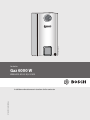
8 716 473 216-00.3O Gas boiler Gaz 6000 W WBN 6000-30-H-E-N/L-S2400 8 716 473 216 (2014/09) en Installation and maintenance instructions for the contractor 2 | Contents Contents 1 Key to symbols and safety instructions . . . . . . . . . . . . . . . . . . . 3 1.1 Key to symbols . . . . . . . . . . . . . . . . . . . . . . . . . . . . . . . . . . 3 1.2 General safety instructions . . . . . . . . . . . . . . . . . . . . . . . . 3 2 Product details . . . . . . . . . . . . . . . . . . . . . . . . . . . . . . . . . . . . . . . . 4 2.1 Standard delivery . . . . . . . . . . . . . . . . . . . . . . . . . . . . . . . 4 2.2 Overview of the gas categories that can be used . . . . . . 4 2.3 Data plate . . . . . . . . . . . . . . . . . . . . . . . . . . . . . . . . . . . . . . 4 2.4 Description of appliance . . . . . . . . . . . . . . . . . . . . . . . . . . 4 2.5 Accessories . . . . . . . . . . . . . . . . . . . . . . . . . . . . . . . . . . . . 4 2.6 Dimensions and minimum clearances . . . . . . . . . . . . . . . 5 2.7 Appliance layout . . . . . . . . . . . . . . . . . . . . . . . . . . . . . . . . 6 2.8 Electrical wiring diagram . . . . . . . . . . . . . . . . . . . . . . . . . . 7 2.9 Technical data . . . . . . . . . . . . . . . . . . . . . . . . . . . . . . . . . . 8 3 Regulations . . . . . . . . . . . . . . . . . . . . . . . . . . . . . . . . . . . . . . . . . . 9 4 Flue gas routing . . . . . . . . . . . . . . . . . . . . . . . . . . . . . . . . . . . . . . . 9 4.1 Approved flue accessories . . . . . . . . . . . . . . . . . . . . . . . . 9 4.2 Installation instructions . . . . . . . . . . . . . . . . . . . . . . . . . . 9 5 Installation . . . . . . . . . . . . . . . . . . . . . . . . . . . . . . . . . . . . . . . . . . . 9 5.1 Important notes . . . . . . . . . . . . . . . . . . . . . . . . . . . . . . . . . 9 5.2 Checking the size of the expansion vessel . . . . . . . . . . 10 5.3 Siting the appliance . . . . . . . . . . . . . . . . . . . . . . . . . . . . 10 5.4 Fitting the appliance . . . . . . . . . . . . . . . . . . . . . . . . . . . 11 5.5 Installation of the supply pipes . . . . . . . . . . . . . . . . . . . 13 5.6 Checking the connections . . . . . . . . . . . . . . . . . . . . . . 13 5.7 Connecting the flue accessories . . . . . . . . . . . . . . . . . . 13 6 Electrical connections . . . . . . . . . . . . . . . . . . . . . . . . . . . . . . . 14 6.1 General notes . . . . . . . . . . . . . . . . . . . . . . . . . . . . . . . . 14 6.2 Connecting appliances with power cable and mains plug 14 6.3 Control unit terminals . . . . . . . . . . . . . . . . . . . . . . . . . . 14 6.3.1 Connecting the on/off controller or Open Therm controller . . . . . . . . . . . . . . . . . . . . . . . . . . . . . . . . . . . . . . . . . . . . . 14 6.3.2 Replacing the power cable . . . . . . . . . . . . . . . . . . . . . . 15 7 8 Commissioning . . . . . . . . . . . . . . . . . . . . . . . . . . . . . . . . . . . . . 7.1 Displays . . . . . . . . . . . . . . . . . . . . . . . . . . . . . . . . . . . . . 7.2 Before commissioning . . . . . . . . . . . . . . . . . . . . . . . . . 7.3 Switching the appliance on/off . . . . . . . . . . . . . . . . . . . 7.4 Setting the maximum flow temperature . . . . . . . . . . . . 7.5 Setting the heating control unit . . . . . . . . . . . . . . . . . . 7.6 After commissioning . . . . . . . . . . . . . . . . . . . . . . . . . . . 7.7 Setting summer mode . . . . . . . . . . . . . . . . . . . . . . . . . . 7.8 Setting frost protection . . . . . . . . . . . . . . . . . . . . . . . . . 15 16 16 16 16 17 17 17 17 9 Service menu settings . . . . . . . . . . . . . . . . . . . . . . . . . . . . . . . 9.1 Operating the service menu . . . . . . . . . . . . . . . . . . . . . 9.2 Service functions overview . . . . . . . . . . . . . . . . . . . . . . 9.2.1 Menu 1 . . . . . . . . . . . . . . . . . . . . . . . . . . . . . . . . . . . . . . 9.2.2 Menu 2 . . . . . . . . . . . . . . . . . . . . . . . . . . . . . . . . . . . . . . 9.2.3 Menu 3 . . . . . . . . . . . . . . . . . . . . . . . . . . . . . . . . . . . . . . 18 18 18 18 20 21 10 Converting the appliance to different gas types . . . . . . . . . 10.1 Converting to a different gas type . . . . . . . . . . . . . . . . 10.2 Gas settings (natural and LPG) . . . . . . . . . . . . . . . . . . 10.2.1 Preparations . . . . . . . . . . . . . . . . . . . . . . . . . . . . . . . . . 10.2.2 Nozzle pressure setting method . . . . . . . . . . . . . . . . . . 22 22 22 22 22 11 Flue gas testing . . . . . . . . . . . . . . . . . . . . . . . . . . . . . . . . . . . . . 11.1 Setting the appliance output . . . . . . . . . . . . . . . . . . . . 11.2 Testing for flue gas tightness . . . . . . . . . . . . . . . . . . . . 11.3 Measuring CO level in flue gas . . . . . . . . . . . . . . . . . . . 11.4 Measuring flue gas loss . . . . . . . . . . . . . . . . . . . . . . . . . 23 23 23 23 23 12 Environment / disposal . . . . . . . . . . . . . . . . . . . . . . . . . . . . . . 24 13 Inspection/Maintenance . . . . . . . . . . . . . . . . . . . . . . . . . . . . . 13.1 Description of various maintenance operations . . . . . 13.1.1 Calling up the last fault saved . . . . . . . . . . . . . . . . . . . . 13.1.2 Opening the appliance . . . . . . . . . . . . . . . . . . . . . . . . . 13.1.3 Cleaning the burner pan, nozzles and burner . . . . . . . 13.1.4 Cleaning the heat exchanger . . . . . . . . . . . . . . . . . . . . 13.1.5 Checking the expansion vessel (also see page 10) . . . 13.1.6 Setting the heating system pressure . . . . . . . . . . . . . . 13.1.7 Checking electrical wiring . . . . . . . . . . . . . . . . . . . . . . . 13.2 Checklist for inspection and maintenance . . . . . . . . . 24 24 24 24 26 26 26 26 26 27 14 Displays . . . . . . . . . . . . . . . . . . . . . . . . . . . . . . . . . . . . . . . . . . . 28 15 Fault mode . . . . . . . . . . . . . . . . . . . . . . . . . . . . . . . . . . . . . . . . . 15.1 Troubleshooting . . . . . . . . . . . . . . . . . . . . . . . . . . . . . . 15.2 Faults that are shown on the display . . . . . . . . . . . . . . 15.3 Faults that are not shown on the display . . . . . . . . . . . 15.4 Sensor values . . . . . . . . . . . . . . . . . . . . . . . . . . . . . . . . 15.4.1 Flow temperature sensor . . . . . . . . . . . . . . . . . . . . . . . 28 28 29 30 30 30 16 Commissioning report for the appliance . . . . . . . . . . . . . . . . 31 Heating pump . . . . . . . . . . . . . . . . . . . . . . . . . . . . . . . . . . . . . . . 17 8.1 Changing the heating circuit pump curve . . . . . . . . . . 17 8.2 Pump anti-seizing function . . . . . . . . . . . . . . . . . . . . . . 17 8 716 473 216 (2014/09) Gaz 6000 W Key to symbols and safety instructions | 3 1 Key to symbols and safety instructions 1.1 Key to symbols Warnings Warnings in this document are identified by a warning triangle printed against a grey background. Keywords at the start of a warning indicate the type and seriousness of the ensuing risk if measures to prevent the risk are not taken. The following keywords are defined and can be used in this document: • NOTICE indicates a situation that could result in damage to property or equipment. • CAUTION indicates a situation that could result in minor to medium injury. • WARNING indicates a situation that could result in severe injury or death. • DANGER indicates a situation that will result in severe injury or death. Important information This symbol indicates important information where there is no risk to people or property. Additional symbols Symbol ▶ • – Explanation Step in an action sequence Cross-reference to another part of the document List entry List entry (second level) Table 1 1.2 – Do not use the telephone or ring doorbells. ▶ Turn off the gas at the meter. ▶ Open windows and doors. ▶ Warn your neighbours and leave the building. ▶ Prevent anyone from entering the building. ▶ Well away from the building: call the fire brigade, police and gas supplier. ▶ CALL The federal governments safety hotline on 13 17 92 ▶ LPG BOILERS Call the supplier’s number on the side of the LPG TANK/ CYLINDER ▶ TURN OFF The ECV (Emergency control valve) at the meter ▶ Put out naked flames ▶ Keep people away from the affected area Intended use This boiler must only be used as a heat appliance in a sealed hot water heating system for domestic purposes. Any other use is considered inappropriate. Any damage that results from such use is excluded from liability. Installation, commissioning and servicing Installation, commissioning and servicing must only be carried out by an authorised contractor. ▶ Carry out a gas tightness test after completing work on gas-carrying components. ▶ Only use original spares. Electrical work Electrical work must only be carried out by a qualified electrician. ▶ Before starting electrical work: – Isolate the mains electrical supply and secure against unintentional reconnection. – Check for zero potential. ▶ Also observe connection diagrams of other system components. Handover to the user General safety instructions These installation instructions are intended for gas fitters, plumbers, heating engineers and electricians. ▶ Read any installation instructions (boiler, heating controls, etc.) carefully before starting the installation. ▶ Observe the safety instructions and warnings. ▶ Observe national and regional regulations, technical rules and guidelines. ▶ Record all work carried out. If you smell gas When handing over, instruct the user how to operate the heating system and inform them about its operating conditions. ▶ Explain how to operate the heating system and draw the user's attention to any safety-relevant action. ▶ Explain that modifications and repairs must only be carried out by an authorised contractor. ▶ Point out the necessity of inspection and servicing for safe and environmentally compatible operation. ▶ Leave the installation instructions and the operating instructions with the user. THIS APPLIANCE IS NOT FOR USE AS A POOL OR SPA POOL HEATER. A gas leak could potentially cause an explosion. If you smell gas, observe the following rules. ▶ Prevent flames or sparks: – Do not smoke, use a lighter or strike matches. – Do not operate any electrical switches or unplug any equipment. Gaz 6000 W 8 716 473 216 (2014/09) 4 | Product details 2 On the data plate, you will find details on the appliance output, approval information and the series number. Product details WBN 6000-30-H-E-N/L-S2400 are appliances for central heating. 2.1 Standard delivery 1 2 3 4 8 716 473 216-01.2O 5 6 • • • • • • • • • • • • • • • Wall-mounted gas boiler Fixing material Set of printed documents for the appliance Flue pipe Grommet Regulator( Only for NG appliance ) 2.2 Description of appliance Gas boiler only for external installation Gas boiler only for central heating Gas boiler for wall installation Power cable Liquid Crystal Display Automatic ignition Continuously controlled output Full backup via the electronics with flame monitoring and solenoid valves according to EN 298 Three-stage heating circuit pump with automatic air vent valve No minimum water circulation rate required Fixed connections for flue gas/combustion air as concentric pipe Ø 60/100 mm Curve-controlled fan Temperature sensor and temperature control for central heating Temperature limiter in the flow Safety valve, pressure gauge, expansion vessel 2.5 Fig. 1 [1] [2] [3] [4] [5] [6] 2.4 Accessories Below is a list of typical accessories for this appliance. You can find comprehensive details of all available accessories in our catalogue. • Digital thermostat Overview of the gas categories that can be used The code number indicates the gas family according to AS 4552: Code number 23 31 Wobbe index (WS) (15 °C) 12.2 - 55.0 MJ/m3 72.9 - 87.2 MJ/m3 Gas type NG LPG Table 2 LPG type1) Commercial Propane Commercial Butane General Product Universal LPG (U-LPG) Use recommended permitted permitted permitted Table 3 1) according to NZS 5435 2.3 Data plate 8 716 473 216-02.3O Fig. 2 8 716 473 216 (2014/09) Gaz 6000 W Product details | 5 Dimensions and minimum clearances ≥ 100 2.6 Ø100 Ø60 ≥ 100 ≥ 100 898 245 R3/4 R1/2 R3/4 R3/4 75 67.75 112.75 132.75 400 440 139.5 300 320 8 716 473 216-03.2O Fig. 3 Gaz 6000 W 8 716 473 216 (2014/09) 6 | Product details 2.7 Appliance layout 1 19 18 17 16 2 15 3 4 20 21 14 5 13 6 7 22 8 9 10 11 23 12 24 25 26 8 716 473 216-04.4O Fig. 4 [1] [2] [3] [4] [5] [6] [7] [8] [9] [10] [11] [12] [13] [14] [15] [16] [17] [18] [19] Expansion vessel Fan Combustion chamber Burner pan with blast tube connection Ignition electrode Safety valve (heating circuit) Automatic air vent valve Heating circuit pump Pump speed selector switch Gas valve Pressure gauge Control device Monitoring electrode Flow temperature sensor Temperature limiter for heating block Air baffle Differential pressure switch Combustion air inlet Flue pipe 8 716 473 216 (2014/09) [20] [21] [22] [23] [24] [25] [26] Front cover for outer casing Main cover for outer casing Back plate for outer casing Interface cap Type plate Plastic cover Base plate for outer casing Gaz 6000 W Product details | 7 2.8 Electrical wiring diagram 1 2 2 3 2 4 2 3 5 6 4 7 8 12 2 9 11 M 10 3 13 2 15 14 GV 16 DIAG TH EXT 3 WAY PUMP FAN N PE L a 17 18 6 720 810 000-10.3O Fig. 5 [1] [2] [3] [4] [5] [6] [7] [8] [9] [10] [11] Differential pressure switch Fan Flow temperature sensor Temperature limiter for heating block Monitoring electrode Ignition electrode Gas valve Cylinder temperature sensor connection (N.A) Turbine (N.A) 3-way valve (N.A) Heating circuit pump Gaz 6000 W [12] [13] [14] [15] [16] [17] [18] Hot water temperature sensor(N.A) 240 V power cable OTM connection or on/off controller 1) Connection for outside temperature sensor Diagnostic interface Transformer Ignition transformer 1) Remove jumper before connection 8 716 473 216 (2014/09) 8 | Product details 2.9 Technical data WBN 6000-30 Max. rated heat output (Pmax) 80/60 °C Max. rated heat input (Qmax), central heating Min. rated heat output (Pmin) 53/47 °C Min. rated heat input (Qmin), central heating Gas supply rate Natural gas type H (Hi(15 °C) = 9.5 kWh/m3) Butane/propane (Hi = 12.9 kWh/kg) Permissible gas supply pressure NG LPG Expansion vessel Pre-charge pressure Total capacity Calculation values for calculating cross-section to EN 13384 Flue gas temperature 80/60 °C max. rated Flue gas temperature 80/60 °C min. rated Flue gas mass flow rate, max. rated Flue gas mass flow rate, min. rated CO2 at max. rated output CO2 at min. rated output Flue gas rating group to G 636/G 635 NOx content NOx class Flue gas connection General data Power supply voltage Frequency Max. power consumption (central heating mode) Standby power consumption Noise output level Max. flow temperature Max. permissible operating pressure (PMS) heating Permissible ambient temperature Nominal capacity of appliance heating Weight (excl. packaging) Dimensions, W x H x D Unit kW kW kW kW NG 30 33.2 9 10.2 LPG 30 33.2 9 10.2 MJ/hr MJ/hr 132.8 – – 132.8 Kpa Kpa 1.13 – – 2.75 bar L 0,5 8 0,5 8 °C °C g/s g/s % % 145 73 13.6 10,3 5.5 – 6.0 2.0 – 2.5 G61/G62 132 3 60/100 145 73 13.5 10,4 5.6 – 7.0 2.3 – 2.8 G61/G62 132 3 60/100 AC ... V Hz W W dB(A) °C bar °C l 240 50 <130 2 38 40 – 82 3 0 – 50 1,6 240 50 <130 2 38 40 – 82 3 0 – 50 1,6 kg mm 42 440 x 898x 315 42 440 x 898x 315 mg/kWh Table 4 8 716 473 216 (2014/09) Gaz 6000 W Regulations | 9 3 Not suitable for pool or spa pool application. Regulations Where no specific instruction is given, reference should be made to the following standards: • AS/NZS 5601 Gas Installations, • AS 1596 LPG storage and handling, • AS 4552 Gas fired water heaters for hot water supply and/or central heating, • AS/NZS 3000 Electrical Installations, • AS1697 Installation and maintenance of steel pipe systems for gas, • AS 4032 Water supply - valves for the control of hot water supply temperatures, • AS 3498 Authorization requirements for plumbing products - water heaters and hot-water storage tanks. • AS 1910 Water supply - float control valves for use in hot and cold water, AS 3500 National plumbing and drainage code. 5.1 Important notes ▶ Before installing the appliance, consult your gas supply utility and your local flue gas inspector [where appropriate]. Fill and top-up water for the heating system Unsuitable fill and top-up water in the heating system can result in the heat exchanger scaling up and failing prematurely. Hardness range soft ( 8.4 °dH) medium (8.4 - 14 °dH) hard (14 °dH) Water treatment not required recommended required Table 5 4 Flue gas routing For straightforward water treatment: ▶ Use the system approved by us. Before fitting the gas boiler and the flue system, check with the local planning authority and flue gas inspector whether there are any restrictions. The surface temperature at the combustion air pipe is below 85 °C for concentric pipes. No minimum clearances to flammable building materials are therefore required. Local regulations may differ from this information and may stipulate minimum clearances to flammable building materials. 4.1 Approved flue accessories The flue accessories form part of the CE approval for the appliance. For this reason, only the provided original flue accessories must be installed. • Flue accessories, concentric pipe Ø 60/100 mm 4.2 Installation instructions Fan stage :1 (Reference to service function 2.b.d ( page 21). CAUTION: Low efficiency and functional problems if an incorrect fan stage is used! ▶ Before fitting the flue kits: Apply a thin coating of solvent-free grease (e.g. Vaseline) to the joint seals. ▶ When fitting the balanced flue, always push the pipe fully home into the sockets. Open vented heating systems ▶ Open vented heating systems must be converted to sealed systems. Gravity fed heating systems ▶ Connect the appliance to the existing pipework via a low loss header with a dirt separator. Galvanised radiators and pipes To prevent gas formation: ▶ Do not use galvanised radiators or pipes. If a room thermostat is used ▶ Do not fit a thermostatic radiator valve to the radiator in the primary room. Anti-freeze The following anti-freeze fluids are permitted: Designation Varidos FSK Alphi - 11 Glythermin NF Antifrogen N Concentration 22 - 55 % 25 - 40 % 20 - 62 % 20 - 40 % Table 6 Corrosion inhibitor The following corrosion inhibitors are permissible: 5 Installation DANGER: Risk of explosion! ▶ Turn off gas valve before working on gas-carrying components. ▶ Check for leaks before working on gas-carrying components. Installation, power connection, connection on the gas and flue gas side and commissioning must only be carried out by a contractor approved for such work by the local gas or power supply authority. Gaz 6000 W Designation Fernox Sentinel Concentration see supplier information see supplier information Table 7 Sealants In our experience, adding sealants to the heating water may result in problems (deposits in the heating block). We therefore advise against using them. Water circulation noises To prevent water circulation noises: ▶ Fit an overflow valve or, with 2-pipe heating systems, a 3-way valve to the radiator furthest from the boiler. 8 716 473 216 (2014/09) 10 | Installation Mono-lever taps and thermostatic mixer taps 5.3 Siting the appliance All mono-lever taps and thermostatic mixer taps can be used. Regulations concerning the installation site LPG O To protect the appliance against excessive pressure: N ▶ Fit a pressure regulator with a safety valve. A 5.2 N M F Flue terminal positions for boilers in accordance with AS5601 J L K G E K G D K H, I G 8 716 473 216-20.1O Fig. 7 T/°C 90 Key to illustration B 80 70 Fan assisted flue terminal position IV A Directly below, an opening window, air vent or other ventilation opening B Below guttering, drain pipes or soil pipes 75mm C Below eaves 300mm D Below balconies or a car port roof* 300mm E From vertical drain pipes or soil pipes 75mm F From internal or external corners 300mm G Above adjacent ground, roof or balcony level 300mm H From a surface facing the terminal 1500mm I From a terminal facing the terminal 1200mm K Vertically from a terminal on the same wall 1500mm L Horizontally from a terminal on the wall 300mm M Adjacent to opening 300mm N Above intersection with roof 500mm O For a vertical structure on the roof III 50 II 40 I A 0 50 Minimum Spacing Terminal Position V 60 100 150 200 250 300 350 400 450 500 VA/l 6 720 610 421-07.2O Fig. 6 I II III IV V tV VA A B F F M G L K A The characteristic curves shown are based on the following key data: • 1% water volume in expansion vessel or 20% of nominal volume of expansion vessel • Differential operating pressure of the safety valve of 0.5 bar, according to DIN 3320 • Pre-charge pressure of expansion vessels matches static head of the system above the heat exchanger • Maximum operating pressure of 3 bar B,C B,C The following diagram provides you with a rough estimate of whether the installed expansion vessel is sufficient or whether an additional expansion vessel is required. 30 C Checking the size of the expansion vessel Pre-charge pressure 0.2 bar Pre-charge pressure 0.5 bar (default setting) Pre-charge pressure 0.75 bar Pre-charge pressure 1.0 bar Pre-charge pressure 1.2 bar Flow temperature System content in litres Operating range of the expansion vessel Additional expansion vessel required ▶ If intersection is on the limit: determine the exact size of the vessel according to DIN EN 12828. ▶ If the intersection is to the right of the curve: install additional expansion vessel. 1000mm 500mm Table 8 Installations in car ports are not recommended. 8 716 473 216 (2014/09) Gaz 6000 W Installation | 11 ▶ Pluming will occur at the terminal so terminal positions where this could cause a nuisance should be avoided. ▶ The air supply and the flue gas exhaust must meet the applicable general regulations. Please consult the instructions provided with the flue terminal kits prior to installation. ▶ The boiler must be installed so that the terminal is exposed to the external air. ▶ It is important that the position of the terminal allows the free passage of air at all times. ▶ Minimum acceptable spacing from the openings are specified above, for domestic situations in accordance with AS 5601. 5.4 Fitting the appliance ▶ Fix the mounting template supplied with the documents to the wall, observing a lateral clearance of at least 100 mm ( page 5). ▶ Drill the holes for the screw hooks according to the mounting template. Combustion air In order to prevent corrosion, the combustion air must not contain any corrosive substances. Substances classed as corrosion-promoting include halogenated hydrocarbons which contain chlorine and fluorine compounds. They may be found in solvents, paints, adhesives, aerosol propellants and household cleaners, for example.. Degreasing baths Printing shops Hairdressing salons Trichloroethylene, tetrachloroethylene, fluorinated hydrocarbons Perchloroethylene, trichloroethylene, methylchloroform Trichloroethylene Aerosol propellants, hydrocarbons containing fluorine and chlorine (difluorodichloromethane) Household sources Cleaning and degreasing Perchloroethylene, methylchloroform, agents trichloroethylene, methylene chloride, carbon tetrachloride, hydrochloric acid Hobby rooms Solvents and thinners Various chlorinated hydrocarbons Aerosols Chlorofluorinated hydrocarbons (Freon) 8 716 473 216-06.1O Industrial sources Chemical cleaners Fig. 8 Mounting template ▶ Remove the mounting template. NOTICE: Residues in the pipework can damage the appliance. ▶ Flush out the system to remove all dirt residues. Table 9 Corrosive materials Surface temperature The maximum surface temperature of the appliance is below 85 °C. That means that no special safety precautions are required with regard to flammable building materials and fitted furniture. If regulations differ in individual countries they must be observed. Gaz 6000 W ▶ Remove packing, taking care to observe the instructions on the packing. ▶ Check the destination country on the type plate and make sure that the gas type specified on the identification plate matches that of the gas supplied by the gas utility company ( page 6). 8 716 473 216 (2014/09) 12 | Installation Taking out inner foam Flipping down the front cover 1. Take out the down foam. 2. Take out the upper foam. 1. Undo screws. 2. Flip the front cover down. 2. 2. 1. 8 716 473 216-13.1O 8 716 473 216-16.1O Fig. 10 1. Fit dowels. 2. Fit screw hooks. 3. Position the appliance on the wall and mount it on the screw hooks. 3. 1. 1. 1. 2. Fig. 9 8 716 473 216-07.3O Fig. 11 Mounting the appliance on the screw hooks Flipping down the control unit The casing is secured with two screws against unauthorised removal (electrical safety). ▶ Always secure the outer casing with these screws. 8 716 473 216 (2014/09) Gaz 6000 W Installation | 13 • Check all joints for leaks with an approved leak tester after connection. 1. Undo screws. 2. Pull the control unit down. 3. Flip the control unit down. Refer to AS/NZS 5601 Installation Code for pipe sizing and details.Ensure that the gas pipe size is correct. If undersized the appliance will not operate correctly .For Natural Gas installations where 3. the inlet pressure exceeds 1.5kPa an appliance regulator is ok reset press 5s mode 6 720 806 640-08.1O supplied.SERVICE CALLS ARE CHARGEABLE FOR UNITS WITH 2. 1. 1. INCORRECT PIPE SIZES OR BLOCKED GAS OR WATER FILTERS. Testing Gas Supply Pipe ▶ Close the gas valve to protect the gas train from pressure damage. ▶ Check sealing points for leaks (testing pressure: max. 15Kpa). ▶ Release the pressure on the gas supply pipe. 5.7 The adapter has been installed in advance.If it need be installed again, please following the below installation instruction. Fig. 12 5.5 Installation of the supply pipes ▶ Determine the internal pipe diameter for the gas supply in accordance with AS/NZS 5601. ▶ All pipe connections in the heating system must be suitable for a pressure of 3 bar. ▶ Install regulator1) (only for NG appliance) and convert connection1). ▶ For filling and draining the system, fit drain & fill valves at the lowest point of the system. ▶ Use corrosion-resistant materials to produce the drain for the safety valve. Such materials include: vitrified clay pipes, hard PVC pipes, PVC pipes, PE-HD pipes, PP pipes, ABS/ASA pipes, cast-iron pipes with enamel lining or coating, steel pipes with plastic coating, stainless steel pipes, borosilicate glass pipes. ▶ The PRV is a safety device for the boiler and if activated may discharge boiling water steam through the relief valve drain line. Connecting the flue accessories ▶ Ensure that the gasket is fitted inside the flue outlet. ▶ Push on the flue gas elbow and secure with the screws supplied. 1 2 3 5.6 8 716 473 216-15.1O CAUTION: ▶ Do not modify or seal off drain pipes. ▶ Pipe work must always slope downwards. Checking the connections Water connections ▶ Open the heating flow and return valves and fill the heating system. ▶ Check sealing points for tightness (testing pressure: max. 2.5 bar at the pressure gauge). Gas Connection: • Fit a union to the water heater gas inlet for easy connection and removal. The thread diameter is 20 mm.THIS DOES NOT INDICATE THE SIZE OF THE GAS SUPPLY. • Fit an AGA / NZGA approved isolating gas valve in the supply line adjacent to the water heater gas connection.. • Ensure that the supply pipe and the gas pressure regulator (LPG or Natural Gas) has sufficient flow capacity for this and other appliances connected to the fitting line. • For LPG appliances ensure that gas cylinders are of sufficient size. • Before connecting the appliance to the gas service, purge any debris or air from the gas service. Fig. 13 Securing flue accessories [1] [2] [3] Screws Flue/adaptor Gasket 1) accessory Gaz 6000 W 8 716 473 216 (2014/09) 14 | Electrical connections 6.3 Fixing the flue pipe 1. Fix the short flue pipe. 2. Fix the flue weather seal. Control unit terminals NOTICE: Cable residues can damage the control unit. ▶ Only remove the insulation from the cable outside the control unit. Flipping down the control unit The casing is secured with two screws against unauthorised removal (electrical safety). ▶ Always secure the outer casing with these screws. 1. 1. Undo screws. 2. Pull the control unit down. 3. Flip the control unit down. 2. 6 720 806 640-08.1O 3. ok 8 716 473 216-14.1O reset press 5s mode Fig. 14 6 Electrical connections 6.1 General notes DANGER: Risk of electric shock ▶ Before carrying out work on electrical components, disconnect the power supply (240 V AC) (fuse, circuit breaker) and secure against unintentional reconnection. 2. 1. 1. Fig. 15 6.3.1 Connecting the on/off controller or Open Therm controller Only operate this appliance with a controller. All appliance modulation, control and safety components are tested and ready-wired for use. The controller must be suitable for mains voltage (from boiler) and must not have its own earth connection. Observe safety measures according to the relevant regulations and AS/ NZS 3000.No other electrical consumer units may be connected to the same power cable. For installation and electrical connection, see the relevant installation instructions. Fuses The appliance is protected by two fuses. They are located on the circuit board. The controller connection on the control unit is located underneath a cover. ▶ Remove the cover. ▶ Remove the jumper from the TH terminals. ▶ Connect the controller to the TH terminals. Replacement fuses are located on the cover of the control unit. T H 3. 6.2 Connecting appliances with power cable and mains plug 1. 2. ▶ Insert the power cable plug into an earthed power socket. 6 720 806 640-16.1O Fig. 16 8 716 473 216 (2014/09) Gaz 6000 W Commissioning | 15 6.3.2 Replacing the power cable 7 Use only original power cable. Commissioning The control unit must be opened to connect the power cable. 7 ▶ Disconnect the ignition cable. ▶ Remove cover. ▶ Remove old cable. ▶ Plug new cable connector on the conductor board. ▶ Plug strain relief to the case. ▶ Mount cover. ▶ Connect ignation cable. 8 6 9 10 ok reset press 5s ok mode 11 12 13 1 1. 2. L PE N 3. 5 4 3 2 14 15 6 720 806 640-17.1O Fig. 17 16 8 716 473 216-08.2O Fig. 18 [1] [2] [3] [4] [5] [6] [7] [8] [9] [10] [11] [12] [13] [14] [15] [16] Gaz 6000 W Drain hose Heating return valve (accessory) Cold water valve (accessory) Gas valve (closed) (accessory) Heating flow valve (accessory) Automatic air vent valve Standby key Display “Back” key (= exit service function/submenu without saving) + key OK button (= confirm selection, save value) – key (mode) Pressure gauge System top-up fixture Test point Cold water supply 8 716 473 216 (2014/09) 16 | Commissioning 7.1 Displays 1 2 3 4 5 6 7 ▶ Press + or – to call up service function 2.b.d ( page 21). ▶ Press OK to switch to the service function. The value flashes on the display. ▶ Press + or – to set the required value. ▶ Hold down OK until the selected service function appears on the display. The display switches to the selected service function automatically. ▶ Press standby. The boiler returns to standard mode. Switching on 6 720 806 640-05.2O Fig. 19 Displays [1] [2] [3] [4] [5] [6] [7] Burner operation Fault display/standby mode display Heating mode active DHW heating active Summer mode active Service Mode Temperature display (in °C) 7.2 ▶ Start the appliance at the standby key. The display shows the heating water flow temperature. Switching off/standby mode ▶ Shut down the appliance at the standby key. Only the warning symbol continues to be displayed. ▶ If the appliance is to be switched off for a longer period of time: observe correct frost protection procedures ( chapter 7.8). Before commissioning NOTICE: Commissioning without water will destroy the appliance. ▶ Only operate the appliance once it has been filled with water. ▶ Adjust pre-charge pressure of expansion vessel to static head of the heating system ( page 10). ▶ Open the automatic air vent valve (leave open) ( Fig. 18, [7], page 15). ▶ Open all system radiator valves. ▶ Open the heating flow valve and heating return valve ( Fig. 18, [6] and [2], page 15). ▶ Fill the heating system to 1 - 2 bar and close the fill valve. ▶ Bleed radiators. ▶ Top up heating system to pressure of 1 - 2 bar. ▶ Check that the gas type specified on the type plate matches that of the gas supply (see Fig. 24). ▶ Open the gas valve ( Fig. 18, [4]). ▶ Plug in the power plug: the appliance enters standby mode. 7.3 Switching the appliance on/off Initial switching on/setting the fan stage At the factory, fan stage 0 is selected, i.e. fan and burner will not start. ▶ Start the appliance at the standby key (Fig. 20). The following fault display is shown: ok 6 720 806 464-06.2O Fig. 21 The appliance has an anti-seizing function which prevents the heating circuit pump and the 3-way valve seizing up following long periods of inactivity. The anti-seizing function remains active during standby mode. 7.4 Setting the maximum flow temperature The maximum flow temperature can be set between 40 °C and approx. 82 °C. The current flow temperature is shown on the display. ▶ Keep pressing – until the symbol appears on the display. ▶ Press OK. The set maximum flow temperature is displayed. ▶ Press + or – to set the required maximum flow temperature. ▶ Press OK to save the setting. The display shows the current flow temperature. You can find typical maximum flow temperatures in Tab. 10. When selecting . ., heating mode is disabled ( appears on the display, summer mode). When the burner is active in heating mode, the burner symbol appear on the display. symbol and the 6 720 806 640-18.3O Fig. 20 Set fan stage: ▶ Determine a suitable fan stage. ▶ Hold down “Back”, + and – at the same time until L.1 is shown on the display. ▶ Press + until L.2 is shown on the display. ▶ Press OK to make settings in menu 2. 8 716 473 216 (2014/09) Flow temperature ..( symbol appears) Approx. 75 °C approx. 82 °C Sample application Summer mode Radiator heating system Convector heating system Table 10 Maximum flow temperature Gaz 6000 W Heating pump | 17 Setting the heating control unit Observe the operating instructions of the heating controller. This shows you: ▶ how to adjust the room temperature, ▶ how to heat economically and save energy. The Bosch TRZ200 Open Therm controller (programmable heating controller) can be used. 7.6 After commissioning ▶ Check the gas supply pressure ( page 22). ▶ Record the settings in the commissioning report ( page 31). 7.7 Setting summer mode The heating circuit pump and consequently central heating are switched off. The DHW and power supply for the heating control unit and timer are retained. NOTICE: Heating system at risk through frost. In summer mode, only the appliance is protected against frost. ▶ Observe frost protection measures where there is a risk of frost ( Chapter 7.8). . To set summer mode: ▶ Keep pressing – until the symbol appears on the display. ▶ Press OK. The set maximum flow temperature is displayed. ▶ Keep pressing – until . . appears on the display. ▶ Press OK to save the setting. is permanently displayed. Additional instructions are contained in the operating instructions for the heating programmer. 7.8 Setting frost protection Frost protection for the heating system: 8 Heating pump 8.1 Changing the heating circuit pump curve The speed of the heating pump can be changed at the pump terminal box. H [m] 7 5 1 3 8 716 473 216-12.1O 7.5 3 21 1 0.0 0.5 1.0 1.5 2.0 2.5 3.0 3.5 Q [m³/h] Fig. 22 [1] [2] [3] [H] [Q] Curve for switch position 1 Curve for switch position 2 Curve for switch position 3 (default setting) Residual head Amount of circulating water ▶ In order to save as much energy as possible and keep flow noise to a minimum, set a low pump curve. 8.2 Pump anti-seizing function This function prevents the heating pump and the 3-way valve seizing up following long periods of inactivity. The anti-seizing function remains active during standby mode. Every time the pump is switched off, a timer is started. If after 24 hours the pump has not run again, it is switched on briefly. Frost protection for the heating system is only ensured if the heating circuit pump is operational and is pumping heating water through the entire system. ▶ Leave the heating switched on. ▶ Set the maximum flow temperature to at least 40 °C (chapter 7.4). -or- If you want to leave the appliance switched off: ▶ Add anti-freeze to the heating water ( page 9) and drain the DHW circuit. For further information, see the heating controller operating instructions. Appliance frost protection: The appliance frost protection function switches the burner and heating circuit pump on when the temperature in the installation room (at temperature sensor for heating flow) falls below 5 °C. This prevents the boiler freezing up. ▶ Activate summer mode ( chapter 7.7) or set the appliance to standby mode ( chapter 7.3). NOTICE: Heating system at risk through frost. In summer/standby mode, only the appliance is protected against frost. Gaz 6000 W 8 716 473 216 (2014/09) 18 | Service menu settings 9 Service menu settings 9.1 Operating the service menu The service menu enables the convenient adjustment and checking of many appliance functions. The service menu splits into three submenus: • Menu 1, for setting level one service functions ( page 19) • Menu 2, for setting level two service functions ( page 20) • Menu 3, for setting the appliance type and output ( page 21) For an overview of service functions, see chapter 9.2 from page 18. Selecting a service function Calling up the service functions is different from one menu to the next. For a description, see the beginning of each menu overview. ▶ Calling up a menu: – Menu 1 ( page 19) – Menu 2 ( page 20) – Menu 3 ( page 21) ▶ Press + or – to scroll through the menu's service functions. Making a setting ▶ Press OK to switch to the service function. The value flashes on the display. ▶ Press + or – to set the required value. Saving a setting ▶ Hold down OK until the selected service function appears on the display. The display switches to the selected service function automatically. If you do not press a key for 15 minutes, the service menu will be closed automatically. Exiting the service function without saving settings ▶ Press standby. The boiler returns to standard mode. Restoring values to standard setting To restore all values from service levels 1 and 2 to their default settings: ▶ Select service function 2.8.E in the second service menu and save value 01. The appliance starts with the default setting. 9.2 Service functions overview 9.2.1 Menu 1 To call up a service function in this menu: ▶ Hold down “Back”, + and – at the same time until L.1 is shown on the display. ▶ Press OK to make settings in menu 1. ▶ Press + or – to scroll through the menu's service functions. The user is responsible for the safety and environmental compliance of the heating system. You should therefore arrange a maintenance and inspection contract with an authorised contractor, covering an annual inspection and demand-dependent maintenance. This guarantees you high efficiency and environmentally compatible combustion. For service/parts and maintenance in AU please contact 1300 30 70 37. For NZS 0800 54 33 52. 8 716 473 216 (2014/09) Gaz 6000 W Service menu settings | 19 Service function 1.2.C Venting function Possible settings/display The venting function can be activated after maintenance. The following settings are possible: • 00: Venting function off • 01: Venting function is switched on and after completion automatically reset to 00 1.2.d Thermal disinfection of the DHW cylinder (WBN 6000-..H..)(N.A) Default setting is 00. • 0: Switched off • 1: Switched on This service function activates the heating of the DHW cylinder to 75 °C. ▶ Implement thermal disinfection as described in chapter 8.2, page 17. Thermal disinfection will not be displayed. 1.2.F Operation Mode Thermal disinfection terminates after the water has been held at 75 °C for 35 minutes. With this service function, you can temporarily change the appliance operating mode. The following settings are possible: • 00: Standard operation; the appliance runs according to controller specifications. • 02: The appliance runs for 15 minutes at the set maximum output. After 15 minutes, the appliance switches to standard mode. • 03: The appliance runs for 15 minutes at minimum output. After 15 minutes, the appliance switches to standard mode. • 04: The appliance runs for 15 minutes at maximum output. After 15 minutes, the appliance switches to standard mode. 1.3.b 1.3.C Time interval for starting and stopping the burner Temperature differential for stopping and restarting the burner Default setting is 0. The time interval determines the minimum delay between the burner stop and restart. Setting range: 1 to 10 minutes. Default setting is 3 minutes. The temperature differential determines the level by which the flow temperature must drop below the set flow temperature before the drop is interpreted as a heat demand. Settings in 1 K steps are possible. The temperature differential can be selected between 0 and 10 K. 1.3.F Duration of heat retention Default setting is 5 K. Heating mode is disabled for this period of time following DHW heating. The following settings are possible: • 1 … 10 minutes 1.5.b Fan run-on time Default setting is 1 minute. This service function allows you to set the fan run-on time. The run-on time can be set from 01 to 18 (10 - 180 seconds). 1.6.A Calling up the last fault saved Standard setting is 03 (30 seconds). The function enables you to retrieve the last fault stored. 1.6.d Current turbine flow rate The service function is reset at 00. The current turbine flow rate is displayed. 1.7.A Liquid crystal display illumination 1.7.C Minimum DHW flow rate(N.A) Possible displays are: • 0.0. - 20.0.: 0.0 to 20 l/min The following settings are possible: • 00: Off • 01: on Default setting is 00. DHW heating is activated if amounts above this value are drawn off. The following settings are possible: • 2.5 … 5 litres per minute Default setting is 2.5 l/min. Table 11 Menu 1 Gaz 6000 W 8 716 473 216 (2014/09) 20 | Service menu settings 9.2.2 Menu 2 To call up a service function in this menu: ▶ Hold down “Back”, + and – at the same time until L.1 is shown on the display. ▶ Press + until L.2 is shown on the display. ▶ Press OK to make settings in menu 2. ▶ Press + or – to scroll through the menu's service functions. Service function 2.1.A Maximum output Possible settings/comments/displays Some gas supply utilities charge a basic rate based on output. The output can be limited to the specific heat demand between the minimum rated output and maximum rated output. Default setting is the maximum rated output. 2.1.b Maximum output (DHW)(N.A) ▶ Set the output in per cent. ▶ Measure the gas flow rate and compare it with the information from the setting tables . If they do not match, change the setting. The output can be limited to the specific heat demand between the minimum rated output and maximum rated output. Default setting is the maximum rated output for DHW. 2.2.b Maximum flow temperature 2.3.d Minimum rated output (heating) 2.4.E 2.8.A 2.8.E Internal parameter Software version Returning the appliance to its standard settings ▶ Set the DHW output in percent. ▶ Measure the gas flow rate and compare it with the information from the setting tables.If they do not match, change the setting. The maximum flow temperature can be set to between 40 °C and 82 °C. Default setting is 85. The output can be set to any percentage value between the minimum and maximum rated output. The default setting is the minimum rated output (heating), which varies according to appliance. Do not change value 0. The current software version is displayed. This service function enables you to reset the appliance to its standard settings. Setting 00. Table 12 Menu 2 8 716 473 216 (2014/09) Gaz 6000 W Service menu settings | 21 Service function 2.9.A Permanent operating mode Possible settings/comments/displays This function permanently sets an operating mode. The following settings are possible: • 00: Standard operation; the appliance runs according to controller specifications. • 01: The appliance runs at minimum output. • 02: The appliance runs at maximum output. 2.9.b 2.9.E Current fan speed Signal turbine delay (WBN 6000-..C..)(N.A) Default setting is 0. Current fan speed in 1/s. Through spontaneous pressure change in the water supply, the flow meter (turbine) can signal that water is being drawn off. This means the burner starts briefly although no water is drawn off. The turbine signal delay can be set from 01 to 06. One step corresponds to 0.25 seconds. 2.9.F Heating circuit pump run-on time Default setting is 02 (0.5 seconds). The pump run-on time is started by the control system at the end of the heat demand. The following settings are possible: • 0 to 10: run-on time in minutes (steps of 1 minute) 2.A.A 2.A.b 2.A.C 2.b.d Temperature at flow temperature sensor DHW temperature (WBN 6000-..C..)(N.A) Temperature at cylinder temperature sensor (WBN 6000-..H..)(N.A) fan stage 2.b.F DHW heating delay (solar mode)(N.A) Default setting is 3 minutes. This service function allows you to display the temperature at the flow temperature sensor. This service function allows you to display the DHW temperature. This service function allows you to display the temperature in the DHW cylinder. This service function allows you to match the fan performance to the flue length. Default setting is 00 (fan does not start). Heating will be suppressed until the DHW temperature sensor detects that the water preheated by solar energy has reached the required outlet temperature. Set the heating delay in accordance with system conditions. The start delay can be set between 0 - 50 seconds. 2.0.A 2.0.B Gas type for appliance type Ionisation current Default setting is 0 (disabled). This service function allows you to set the gas type. Possible displays are: • 00: Appliance for natural gas • 01: Appliance for LPG • With operational burner: – 1 A = OK – < 1 A = faulty • With burner off: – < 1 A = OK – 1 A = faulty Table 12 Menu 2 9.2.3 Menu 3 To call up a service function in this menu: ▶ Hold down “Back”, + and – at the same time until L.1 is shown on the display. ▶ Press + until L.3 is shown on the display. ▶ Press OK to make settings in menu 3. ▶ Press + or – to scroll through the menu's service functions. Service function 3.1.A Appliance type, output, DHW heating Possible settings/comments/displays This service function allows you to adjust the control unit to the appliance output and the type of DHW heating. This is necessary when the control unit is replaced. Table 13 Menu 3 Gaz 6000 W 8 716 473 216 (2014/09) 22 | Converting the appliance to different gas types 10 Converting the appliance to different gas types 1 10.1 Converting to a different gas type 2 The following gas conversion kits are available: Appliance Conversion to WBN 6000-30-H-E-N/L-S2400 LPG NG Part no. 8 733 201 156 8 733 201 155 3 Table 14 DANGER: Risk of explosion! ▶ Turn off gas valve before working on gas-carrying components. ▶ Check for leaks before working on gas-carrying components. 4 5 6 720 806 640-19.1O Fig. 24 Gas train ▶ Install the conversion kit according to the accompanying installation instructions. ▶ Make the gas settings after every conversion ( section 10.2). [1] [2] [3] [4] [5] Test port (for nozzle pressure) Adjusting screw, maximum gas volume Cap Adjusting screw, minimum gas volume Test nipple for gas supply pressure 10.2 Gas settings (natural and LPG) 10.2.2 Nozzle pressure setting method 10.2.1 Preparations Nozzle pressure at maximum output ▶ Flip the control unit down ( page 12). ▶ Mount the control unit at the bottom of the appliance so that the gas train and the control unit can be operated at the same time. ▶ Select service function 1.2.F and operating mode 04 (= maximum rated output) ( page 19). ▶ Loosen the sealing screw at the test nipple for the nozzle pressure ( Fig. 24, [1]) and connect the U-tube pressure gauge. ▶ Remove the cover ( Fig. 24, [4]). ▶ For “max.” specified nozzle pressure (mbar). Use the setting screw to set the nozzle pressure for the max. gas volume ( Fig. 24, [2]). Turn clockwise = more gas; turn anti-clockwise = less gas. Nozzle pressure at minimum output ▶ Select service function 1.2.F and operating mode 03 (= minimum rated output) ( page 19). ▶ For “min.” specified nozzle pressure (mbar). Use the setting screw to set the nozzle pressure for the min. gas volume ( Fig. 24, [3]). ▶ Check the set min. and max. values and correct them if required. Checking the gas supply pressure 8 716 473 216-09.1O Fig. 23 Control unit, mounted in the frame, allowing the gas train and control unit to be operated at the same time The rated output can be set using the nozzle pressure or volumetrically. ▶ Always initially adjust at maximum output and then at minimum outout. ▶ To ensure heat transfer, open radiator valves or hot water draw-off point. ▶ Switch off the gas boiler, close the gas valve, remove the U-tube pressure gauge and tighten the sealing screw [1]. ▶ Loosen the sealing screw at the test nipple for the gas supply pressure ( Fig. 24, [5]) and connect the pressure gauge. ▶ Open the gas valve and switch on the gas boiler. ▶ Select service function 1.2.F and operating mode 04 (= maximum rated output) ( page 19). ▶ Check required gas supply pressure according to table. Nominal [Kpa] 1.13 Permissible pressure range at max. rated output [Kpa] 1.13 - 3.0 2.75 2.5 - 3.5 pressure Gas type Natural gas H (23) LPG (Propane)1) LPG (Butane) Table 15 1) Standard figure for LPG with fixed cylinders with capacities up to 15 000 l 8 716 473 216 (2014/09) Gaz 6000 W Flue gas testing | 23 Never commission the appliance above or below these values. Identify the cause and rectify the fault. Where that is not possible, isolate the appliance from the gas side and notify the customer. Resetting the appliance to standard operating mode ▶ Select service function 1.2.F and operating mode 00 (= standard mode) ( page 19). ▶ Switch off the appliance, close the gas valve, remove the pressure gauge and tighten the sealing screw. ▶ Reattach the cover and seal it. 11 Flue gas testing 11.1 Setting the appliance output To select the maximum appliance output: ▶ Select service function 1.2.F and operating mode 04 ( page 19). To select the minimum appliance output: ▶ Select service function 1.2.F and operating mode 03 ( page 19). ▶ Measure the O2 or CO2 level. ▶ Select service function 1.2.F and operating mode 00 ( page 19). ▶ switch off the appliance. ▶ Remove the probe. ▶ Refit plug. 11.3 Measuring CO level in flue gas A multi-port probe is required for carrying out the test. ▶ To ensure heat transfer, open radiator valves or hot water draw-off point. ▶ Switch on the appliance and wait a few minutes. ▶ Remove the sealing plug from the flue gas testing socket (1). ▶ Insert the probe as far as it will go into the test port. ▶ Seal the test port. ▶ Select service function 1.2.F and operating mode 04 ( page 19). ▶ Measure the CO level. ▶ Select service function 1.2.F and operating mode 00 ( page 19). ▶ switch off the appliance. ▶ Remove the probe. ▶ Refit plug. You have 15 minutes in which to take your measurements. Afterwards, the appliance returns to standard mode. To select Standard mode: ▶ Select service function 1.2.F and operating mode 00 ( page 19). -or▶ Press standby. The boiler returns to standard mode. 2 You can test for flue gas tightness by measuring the O2 or CO2 content of the combustion air. FLUE FLUE 8 716 473 216-17.1O Fig. 26 [1] [2] 11.2 Testing for flue gas tightness 1 Test port for flue gas Test port for combustion air 11.4 Measuring flue gas loss A flue gas probe and a temperature sensor are required for carrying out the test. An annular gap probe is required for carrying out the test. This test is only possible with flue routing type C12 and C32. The O2 level must not be below 20.6 %. The CO2 level must not exceed 0.2 %. ▶ To ensure heat transfer, open radiator valves or hot water draw-off point. ▶ Switch on the appliance and wait a few minutes. ▶ Remove the sealing plug from the combustion air testing socket (2). ▶ Insert the probe into the test port. 2 1 FLUE FLUE ▶ To ensure heat transfer, open radiator valves or hot water draw-off point. ▶ Switch on the appliance and wait a few minutes. ▶ Remove the sealing plug from the flue gas testing socket (1). ▶ Insert the flue gas probe approx. 60 mm into the test port or to the position at which the flue gas temperature is highest. ▶ Seal the test port. ▶ Remove the sealing plug from the combustion air testing socket (2). ▶ Push the temperature sensor approx. 20 mm into the port. ▶ Seal the test port. ▶ Select service function 1.2.F and operating mode 04 ( page 19). ▶ Measure the flue gas loss or boiler efficiency at a boiler temperature of 60 °C. ▶ Select service function 1.2.F and operating mode 00 ( page 19). ▶ switch off the appliance. ▶ Remove the probe. ▶ Remove the temperature sensor. ▶ Refit plug. 8 716 473 216-17.1O Fig. 25 [1] [2] Test port for flue gas Test port for combustion air ▶ Seal the test port. ▶ Select service function 1.2.F and operating mode 04 ( page 19). Gaz 6000 W 8 716 473 216 (2014/09) 24 | Environment / disposal Important notes 12 Environment / disposal Environmental protection is a fundamental corporate strategy of the Bosch Group. The quality of our products, their efficiency and environmental safety are all of equal importance to us and all environmental protection legislation and regulations are strictly observed. We use the best possible technology and materials for protecting the environment taking into account of economic considerations. Packaging We participate in the recycling programmes of the countries in which our products are sold to ensure optimum recycling. All of our packaging materials are environmentally friendly and can be recycled. Used appliances Used appliances contain valuable materials that should be recycled. The various assemblies can be easily dismantled and synthetic materials are marked accordingly. Assemblies can therefore be sorted by composition and passed on for recycling or disposal. For an overview of faults, see page 29. • The following test equipment is required: – Electronic flue gas emission meter for CO2 , CO and exhaust temperature – Pressure gauge for 0 - 30 mbar (resolution at least 0.1 mbar) • Special tools are not required • Permissible lucricants: – For components in contact with water: Unisilkon L 641 (8 709 918 413). – Unions: HFt 1 v 5 (8 709 918 010). ▶ Use 8 719 918 658 as heat conducting paste. ▶ Only use genuine spare parts! ▶ Refer to the spare parts catalogue when ordering spare parts. ▶ Always renew seals and O-rings removed during servicing or repair work. After inspection/maintenance 13 Inspection/Maintenance To ensure that gas consumption and environmental impact remain as low as possible over an extended period of time, we recommend that you take out an inspection/maintenance contract with an authorised contractor covering an annual inspection, and maintenance at other times as required. DANGER: Risk of explosion! ▶ Turn off gas valve before working on gas-carrying components. ▶ Check for leaks before working on gas-carrying components. ▶ Retighten all loosened threaded fittings. ▶ Recommission the appliance ( page 15). ▶ Check all connections for leaks. 13.1 Description of various maintenance operations 13.1.1 Calling up the last fault saved ▶ Select service function 1.6.A ( page 19). For an overview of faults, see page 29. 13.1.2 Opening the appliance DANGER: Risk of poisoning ▶ Check for leaks before working on gas-carrying components. Taking down flue pipe 1. Take down the sealing. 2. Take the short flue pipe. DANGER: Risk of electric shock ▶ Before carrying out work on electrical components, disconnect the power supply (240 V AC) (fuse, circuit breaker) and secure against unintentional reconnection. 2. WARNING: Risk of scalding Hot water can lead to severe scalding. 1. ▶ Close all valves and possibly drain appliance prior to working on parts carrying water. NOTICE: Escaping water can damage the electronics. ▶ Cover the electronics prior to working on parts carrying water. 8 716 473 216-18.1O Fig. 27 8 716 473 216 (2014/09) Gaz 6000 W Inspection/Maintenance | 25 Flipping down the front cover 1. Undo screws. 2. Pull the control unit down. 3. Flip the control unit down. 1. Undo the screws. 2. Flip the front cover down. 6 720 806 640-08.1O 3. ok 2. reset press 5s mode 2. 1. 1. Fig. 29 Removing the front casing 8 716 473 216-16.1O The front casing is secured with two screws against unauthorised removal (electrical safety). ▶ Always secure the outer casing with these screws. 1. 1. Remove both safety screws from the appliance front. 2. Lift off the case. 1. Fig. 28 Flipping down the control unit The casing is secured with two screws against unauthorised removal (electrical safety). ▶ Always secure the outer casing with these screws. 2. 1. 1. 8 716 473 216-11.2O Fig. 30 Gaz 6000 W 8 716 473 216 (2014/09) 26 | Inspection/Maintenance 13.1.3 Cleaning the burner pan, nozzles and burner 13.1.4 Cleaning the heat exchanger ▶ Loosen five screws and lift out the combustion chamber cover by pulling it forwards. 1. Disconnect the cable. 2. Remove screw fittings. 3. Pull the heat exchanger out towards the front. 1 1. 2 6 720 806 640-15.2O 6 720 806 640-11.2O 3. Fig. 31 Opening the burner [1] [2] Screws Combustion chamber cover ▶ Remove burner. ▶ Remove the nozzle holder. ▶ Clean burner using a brush. Ensure that the blades and nozzles are clear. Do not use a metal brush to clean the nozzles. ▶ Check electrodes for contamination and clean or replace if required. ▶ Check the gas setting ( page 22). 1 2. 2. Fig. 33 ▶ Clean the heat exchanger in water using a rinsing agent and reinstall it. ▶ Carefully straighten any distorted fins on the heat exchanger. 13.1.5 Checking the expansion vessel (also see page 10) According to DIN 4807, Part 2, Section 3.5, the expansion vessel must be checked annually. 2 ▶ Depressurise the appliance. ▶ Adjust the pre-charge pressure of the expansion vessel to the static head of the heating system, if necessary. 13.1.6 Setting the heating system pressure NOTICE: Damage to appliance due to cold water! Stress cracks can occur on the hot heat exchanger when the heating water is topped up. ▶ Only top up the heating water when the appliance is cold. 4 Pressure gauge reading 1 bar Minimum system pressure (when cold) 1 - 2 bar Optimum system pressure 3 bar Maximum system pressure at highest heating water temperature:: must not be exceeded (safety valve opens). 3 6 720 806 640-10.3O Table 16 Fig. 32 [1] [2] [3] [4] Blast tube connection Burner half Gas train Nozzle ▶ If the pointer is below 1 bar (when the system is cold), top up with water to the system until the pointer is between 1 bar and 2 bar again. ▶ If there is a pressure drop: check the expansion vessel and heating system for leaks. 13.1.7 Checking electrical wiring ▶ Check wiring for mechanical damage and replace faulty cables/leads. 8 716 473 216 (2014/09) Gaz 6000 W Inspection/Maintenance | 27 13.2 Checklist for inspection and maintenance Date 1 2 Call up the last fault saved in the electronics, service function 1.6.A ( page 19). Perform a visual check of the air/flue gas routing. 3 Check the gas supply pressure, ( page 22). mbar 4 Check for leaks on the gas and water connections ( page 13). 5 Check heat exchanger, ( page 26). 6 Check burner ( page 26). 7 Check electrodes ( page 26). 8 9 Check the expansion vessel pre-charge pressure matches the static head of the heating system. Check the heating system pressure. 10 Check electrical wiring for damage. 11 Check the heating controller settings. 12 Check the set service functions. bar bar Table 17 Gaz 6000 W 8 716 473 216 (2014/09) 28 | Displays 14 Displays 15 The display shows the following (tab.Fig. 18 andFig. 19): Value displayed Number, point, number or letter, point followed by a letter Letter followed by number or letter Two numbers or one number, point followed by number Fault mode 15.1 Troubleshooting Description Service function ( Tab. 11 to Tab. 13, page 19 to 21) DANGER: Risk of explosion! ▶ Turn off gas valve before working on gas-carrying components. ▶ Check for leaks before working on gas-carrying components. Fault code flashes ( Tab. 20, page 29) Decimal figure e.g. flow temperature DANGER: Risk of poisoning ▶ Check for leaks before working on gas-carrying components. or Three numbers Table 18 Displays DANGER: Risk of electric shock ▶ Before carrying out work on electrical components, disconnect the power supply (240 V AC) (fuse, circuit breaker) and secure against unintentional reconnection. Special display Description Venting function enabled (approx. 2 minutes). Summer mode (appliance frost protection) e.g. EA only WARNING: Risk of scalding Hot water can lead to severe scalding. Fault code ( chapter 15.1) Fan stage 0 is set, service function 2.b.d. Standby ▶ Close all valves and possibly drain appliance prior to working on parts carrying water. NOTICE: Escaping water can damage the electronics. ▶ Cover the electronics prior to working on parts carrying water. Table 19 Special displays All safety, modulation and control components are monitored by the Heatronic system. If a fault occurs during operation, the display shows the possibly , and a fault code (e.g. EA) flashes. If and symbol and appear: ▶ Press and hold down OK until the and symbols are no longer displayed. The appliance will start up again and the flow temperature will be displayed. If only appears: ▶ Switch the appliance first off and then on again by means of the standby key. The appliance will start up again and the flow temperature will be displayed. If a fault persists: ▶ Contact your approved installer or Customer Service for assistance, providing details of the fault and the appliance. For an overview of faults, see page 29. For an overview of displays, see page 28. If a fault persists: ▶ Check the circuit board, replace it if required and reset the service functions. 8 716 473 216 (2014/09) Gaz 6000 W Fault mode | 29 15.2 Faults that are shown on the display Display code A7 Description Temperature sensor for hot water is faulty. Remedy ▶ Check the temperature sensor and connecting lead for breaks or short-circuits; replace them if required. Ad C1 Cylinder temperature sensor not detected. Fan speed too low. C4 C6 The differential pressure switch will not respond if the fan is switched off. Pressure switch not closing. Check cylinder temperature sensor and connecting lead. ▶ Check power supply. ▶ Check flue gas system; clean or repair if required. Check pressure switch and wiring, check connection hoses. C7 CE d7 Fan not running. Filling pressure of the heating system is too low. Gas valve faulty. E2 E9 EA F7 FA P Fd Check fan lead and connector, check fan, replace as necessary. Check pressure switch, sensor and connecting pipes. Check fan lead and connector, check fan, replace as necessary. ▶ Top up the system with water. ▶ Check lead. ▶ Check gas train; replace if required. Flow temperature sensor faulty (lead break). Check the temperature sensor and connecting lead for breaks or shortcircuits. Temperature limiter for heating block has ▶ Check heat exchanger temperature limiter and lead for breaks; responded. replace if required. ▶ Check the operating pressure of the heating system. ▶ Check temperature limiter; replace if required. ▶ Check pump starter; replace pump if required. ▶ Check the fuse; replace if required ( page 7). ▶ Bleed the appliance. ▶ Check heating block on the water side; replace if required. ▶ Check flue gas temperature limiter and lead for breaks; replace if required. Flame not detected. ▶ Check earth lead is correctly connected. ▶ Check whether gas valve is open. ▶ Check gas supply pressure; correct if required. ▶ Check power supply. ▶ Check electrodes with lead; replace if required. ▶ Check flue gas system; clean or repair if required. ▶ Check gas settings; correct if required. ▶ For natural gas: Check external gas flow limiter; replace if required. ▶ For open flue operation, check air supply or ventilation apertures. ▶ Clean heat exchanger ( page 26). ▶ Check gas train; replace if required. A flame is detected although the appliance is ▶ Check electrodes for contamination; replace if required. switched off. ▶ Check flue gas system; clean or repair if required. ▶ Check PCB for moisture; dry if required. A flame is detected after the gas has been switched ▶ Check gas train; replace if required. off. ▶ Check electrodes and lead; replace if required. ▶ Check flue gas system; clean or repair if required. Fan stage not selected. ▶ Select fan stage. Appliance type not defined. Key was held down for too long (over 30 secs). ▶ Set appliance type ( service function 3.1.A). ▶ Press the key again for less than 30 secs. Table 20 Gaz 6000 W 8 716 473 216 (2014/09) 30 | Fault mode 15.3 Faults that are not shown on the display Appliance faults Flow noises Heat-up takes too long Flue gas readings incorrect; CO levels too high Ignition too violent, poor DHW outlet temperature is not reached Remedy ▶ Correctly set the pump speed at the pump terminal box. ▶ Correctly set the pump speed at the pump terminal box. ▶ Check gas type. ▶ Check gas supply pressure; adjust if required. ▶ Check flue gas system; clean or repair if required. ▶ Check gas settings; replace gas train if required. ▶ Check gas type. ▶ Check gas supply pressure; adjust if required. ▶ Check power supply. ▶ Check electrodes with lead; replace if required. ▶ Check flue gas system; clean or repair if required. ▶ Check gas settings; replace gas train if required. ▶ For natural gas: Check external gas flow limiter; replace if required. ▶ Check burner; replace if required. ▶ Check appliance type and gas type; see service function 2.0.A. ▶ Check turbine. Replace if required. Table 21 Faults that are not shown on the display 15.4 Sensor values 15.4.1 Flow temperature sensor Temperature/ °C Measuring tolerance 10 % 0 10 20 30 40 50 60 70 80 90 Resistance/ 33 242 19 947 12 394 7 947 5 242 3 548 2 459 1 740 1 256 923 Table 22 8 716 473 216 (2014/09) Gaz 6000 W Commissioning report for the appliance | 31 16 Commissioning report for the appliance Customer/system user: Surname, first name Street, house number Telephone/fax Postcode, town System installer: Order number: (Complete a separate report for every appliance!) Appliance type Serial number: Date commissioned: Individual appliance | Cascade, Number of appliances: ...... Boiler room: Cellar | Attic | Other: cm2 Ventilation apertures: Number: ......, Size: approx. Flue routing: Twin pipe system | LAS | Duct | Separate pipe routing Plastic | Stainless steel | Aluminium Total length: approx. ...... m | 90 ° bend: ...... pce | 15 - 45 ° bend: ...... pce Flue tightness test (with combustion air flowing in countercurrent): Yes | No CO2 value in the combustion air at maximum rated output: % O2 value in the combustion air at maximum rated output: % Notes regarding underpressure or overpressure operation: Gas setting and flue gas test: Set gas type: Natural gas H | Propane | Butane Gas supply pressure: Kpa Gas static supply pressure: Kpa Selected maximum rated output: kW Selected minimum rated output: kW Gas flow rate at maximum rated output: Net calorific value HiB: Measuring the flue gas loss at maximum rated output: CO at maximum rated output: mj/hr Gas flow rate at minimum rated output: mj/hr kWh/m3 % ppm Measuring the flue gas loss at minimum rated output: CO at minimum rated output: % ppm Flue gas temperature at maximum rated output: °C Flue gas temperature at minimum rated output: °C Maximum measured flow temperature: °C Minimum measured flow temperature: °C System hydraulics: Low loss header, type: Heating circuit pump: Additional expansion vessel Size/pre-charge pressure: Automatic air vent valve installed? Yes | No DHW cylinder/type/number/heating surface output: System hydraulics checked, notes: Gaz 6000 W 8 716 473 216 (2014/09) 32 | Commissioning report for the appliance Modified service functions: (Select the modified service functions and enter the values here.) Example: service function 1.7.A changed from 00 to 01 Heating control unit: Heating control unit set, notes: Modified heating control unit settings documented in the controller operating/installation instructions The following work has been carried out: Electrical connections checked, notes: Combustion air/flue gas test carried out Function check carried out Was a tightness test carried out on the gas and water sides? Commissioning includes checking the settings, a visual boiler tightness test and a function check of the boiler and control unit. The system installer conducts a test of the heating system. If minor installation faults are identified on Bosch components during commissioning, Bosch is fully prepared to rectify these faults once consent has been given by the customer. This does not imply any liability for the installation performance. The system named above has been checked to the extent described. The documents have been handed over to the user. The user has been made aware of the safety information and operation of the abovementioned heat source, including accessories. Attention has been drawn to the requirement for regular maintenance of the abovementioned heating system. ___________________________________________________________ Name of service engineer __________________________________________________________ Date, user's signature Affix the test report here. ________________________________________________ Date, system installer's signature 8 716 473 216 (2014/09) Gaz 6000 W | 33 Notes Gaz 6000 W 8 716 473 216 (2014/09) 34 | Notes 8 716 473 216 (2014/09) Gaz 6000 W | 35 Notes Gaz 6000 W 8 716 473 216 (2014/09)