1
Dell PowerEdge VRTX Enclosure
Owner's Manual
Regulatory Model: E22S
Regulatory Type: E22S001
Notes, Cautions, and Warnings
NOTE: A NOTE indicates important information that helps you make better use of your computer.
CAUTION: A CAUTION indicates either potential damage to hardware or loss of data and tells you how to avoid the
problem.
WARNING: A WARNING indicates a potential for property damage, personal injury, or death.
Copyright © 2014 Dell Inc. All rights reserved. This product is protected by U.S. and international copyright and intellectual property
laws. Dell™ and the Dell logo are trademarks of Dell Inc. in the United States and/or other jurisdictions. All other marks and names
mentioned herein may be trademarks of their respective companies.
2014 - 10
Rev. A02
Contents
1 About your system...................................................................................................................... 8
Introduction.............................................................................................................................................................. 8
Terms used in the document..............................................................................................................................8
System overview.......................................................................................................................................................9
Server module and hard-drive numbering — tower mode..............................................................................10
Server module and hard-drive numbering — rack mode................................................................................ 14
Front-panel features and indicators....................................................................................................................... 18
KVM features................................................................................................................................................... 20
Hard-drive indicator patterns...........................................................................................................................20
LCD module...................................................................................................................................................... 21
Back-panel features and indicators....................................................................................................................... 24
Power supply indicators...................................................................................................................................25
Blower module indicators................................................................................................................................ 26
I/O module indicators....................................................................................................................................... 27
CMC indicators.................................................................................................................................................28
CMC features................................................................................................................................................... 28
CMC fail-safe mode..........................................................................................................................................29
Configuration wizard...............................................................................................................................................29
System messages................................................................................................................................................... 30
LCD messages........................................................................................................................................................ 30
Documentation matrix............................................................................................................................................ 31
Quick Resource Locator...................................................................................................................................32
2 Initial system configuration..................................................................................................... 33
Before you begin.....................................................................................................................................................33
Initial setup sequence............................................................................................................................................ 33
Logging in to the CMC.............................................................................................................................................34
3 Configuring enclosure components.......................................................................................35
Fabric A...................................................................................................................................................................35
Fabrics B and C.......................................................................................................................................................35
I/O module and PCIe mezzanine card configuration guidelines.............................................................................35
Supported I/O modules........................................................................................................................................... 36
Configuring network settings for the I/O module....................................................................................................36
Mapping PCIe expansion slots............................................................................................................................... 36
Managing PCIe slots...............................................................................................................................................37
Managing chassis storage..................................................................................................................................... 38
4 Installing enclosure components........................................................................................... 39
Recommended tools............................................................................................................................................... 39
Front bezel (optional).............................................................................................................................................. 39
Installing the front bezel...................................................................................................................................39
Removing the front bezel..................................................................................................................................40
System feet—tower mode......................................................................................................................................40
Removing the system feet................................................................................................................................ 40
Installing the system feet................................................................................................................................. 41
Wheel assembly (optional)—tower mode..............................................................................................................41
Installing the wheel assembly..........................................................................................................................41
Removing the wheel assembly.........................................................................................................................44
Removing and installing the system cover............................................................................................................. 45
Opening the system..........................................................................................................................................45
Closing the system........................................................................................................................................... 46
Inside the system....................................................................................................................................................46
Hard drives..............................................................................................................................................................47
Removing a 2.5 inch hard-drive blank.............................................................................................................. 48
Installing A 2.5 Inch Hard-Drive Blank............................................................................................................. 48
Removing a 3.5 inch hard-drive blank.............................................................................................................. 48
Installing a 3.5 inch hard-drive blank............................................................................................................... 49
Removing a hot-swap hard drive..................................................................................................................... 49
Installing a hot-swap hard drive...................................................................................................................... 50
Removing a hard drive from a hard-drive carrier.............................................................................................50
Installing a hard drive into a hard-drive carrier............................................................................................... 52
Server modules.......................................................................................................................................................52
Removing a server module...............................................................................................................................53
Configuring a server module............................................................................................................................ 54
Installing a server module................................................................................................................................55
Server module partitions........................................................................................................................................ 55
Removing the server module partitions........................................................................................................... 56
Installing the server module partitions.............................................................................................................58
Power supplies....................................................................................................................................................... 60
Power supply blanks........................................................................................................................................ 60
Removing a power supply................................................................................................................................ 61
Installing a power supply................................................................................................................................. 64
Cooling shroud........................................................................................................................................................65
Removing the cooling shroud...........................................................................................................................65
Installing the cooling shroud............................................................................................................................66
Cooling fans............................................................................................................................................................ 67
Removing a cooling fan....................................................................................................................................67
Installing a cooling fan..................................................................................................................................... 68
Cooling-fan assembly............................................................................................................................................. 68
Removing the cooling-fan assembly................................................................................................................ 68
Installing the cooling-fan assembly................................................................................................................. 70
Blower modules......................................................................................................................................................70
Removing a blower module..............................................................................................................................70
Installing a blower module............................................................................................................................... 71
Removing the blower module bay....................................................................................................................72
Installing the blower module bay..................................................................................................................... 72
I/O module...............................................................................................................................................................73
Removing the I/O module................................................................................................................................. 73
Installing the I/O module.................................................................................................................................. 74
Optical drive (optional)............................................................................................................................................74
Removing the optical drive...............................................................................................................................74
Installing the optical drive................................................................................................................................76
CMC cards.............................................................................................................................................................. 76
CMC card indicators........................................................................................................................................ 77
Removing a CMC card......................................................................................................................................77
Installing a CMC card.......................................................................................................................................78
PCIe cage................................................................................................................................................................78
Removing the PCIe cage door..........................................................................................................................79
Installing the PCIe cage door...........................................................................................................................80
Removing the PCIe cage.................................................................................................................................. 80
Installing the PCIe cage................................................................................................................................... 82
Expansion cards..................................................................................................................................................... 82
Expansion card installation guidelines.............................................................................................................82
Expansion card operational power status....................................................................................................... 83
PCIe slot indicators.......................................................................................................................................... 84
Removing a low profile expansion card...........................................................................................................85
Installing a low profile expansion card............................................................................................................ 86
Removing the low profile expansion card divider unit.....................................................................................87
Installing the low profile expansion card divider unit...................................................................................... 88
Removing a full height expansion card............................................................................................................ 89
Installing a full height expansion card............................................................................................................. 90
Removing the full-height expansion-card divider unit..................................................................................... 91
Installing the full height expansion card divider unit....................................................................................... 92
Removing the expansion card riser................................................................................................................. 93
Installing the expansion card riser...................................................................................................................94
Double-wide GPGPU card (optional)...................................................................................................................... 94
Removing a double-wide GPGPU card.............................................................................................................95
Installing a double-wide GPGPU card..............................................................................................................97
Integrated storage controller cards....................................................................................................................... 99
Storage controller operational power status.................................................................................................100
Storage controller indicators......................................................................................................................... 101
Removing an integrated storage controller card........................................................................................... 102
Installing an integrated storage controller card............................................................................................ 103
System battery......................................................................................................................................................104
Replacing the system battery.........................................................................................................................104
System top and base covers.................................................................................................................................105
Removing the system top and base covers....................................................................................................105
Installing the system top and base covers.....................................................................................................106
Mounting ears.......................................................................................................................................................107
Removing the mounting ears..........................................................................................................................107
Installing the mounting ears...........................................................................................................................108
Replacing the LCD module............................................................................................................................. 109
Control panel assembly........................................................................................................................................ 109
Removing the control panel........................................................................................................................... 109
Installing the control panel.............................................................................................................................110
Removing the control panel board................................................................................................................. 111
Installing the control panel board.................................................................................................................. 112
Backplane expander boards.................................................................................................................................113
Removing a backplane expander board........................................................................................................ 113
Installing a backplane expander board..........................................................................................................114
Hard-drive backplane........................................................................................................................................... 115
Removing the hard-drive backplane.............................................................................................................. 115
Installing the hard-drive backplane............................................................................................................... 117
Power distribution board...................................................................................................................................... 118
Removing the power distribution board.........................................................................................................118
Installing the power distribution board.......................................................................................................... 120
System board........................................................................................................................................................ 120
Removing the system board........................................................................................................................... 120
Installing the system board............................................................................................................................ 123
Power pass-through board...................................................................................................................................123
Removing the power pass-through board......................................................................................................124
Installing the power pass-through board.......................................................................................................125
Midplane...............................................................................................................................................................126
Removing the midplane..................................................................................................................................126
Installing the midplane................................................................................................................................... 128
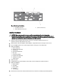
5 Converting the system from tower mode to rack mode....................................................130
Safety instructions................................................................................................................................................130
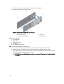
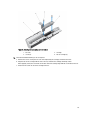
Preparing a system for conversion from tower mode to rack mode.................................................................... 130
Installing the enclosure in a rack......................................................................................................................... 134
6 Troubleshooting your system................................................................................................135
Safety first—for you and your system..................................................................................................................135
Responding to a systems management alert message........................................................................................ 135
Troubleshooting external connections.................................................................................................................135
Troubleshooting a damaged enclosure................................................................................................................135
Troubleshooting enclosure components..............................................................................................................136
Troubleshooting a wet enclosure.................................................................................................................. 136
Troubleshooting power supplies....................................................................................................................137
Troubleshooting blower modules...................................................................................................................137
Troubleshooting the system battery...............................................................................................................137
Troubleshooting cooling problems.................................................................................................................138
Troubleshooting cooling fans.........................................................................................................................138
Troubleshooting an optical drive....................................................................................................................138
Troubleshooting a storage controller.............................................................................................................139
Troubleshooting hard drives.......................................................................................................................... 139
Troubleshooting expansion cards..................................................................................................................140
Troubleshooting the I/O module.....................................................................................................................140
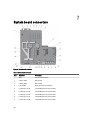
7 System board connectors......................................................................................................142
8 Technical specifications........................................................................................................145
9 Getting help.............................................................................................................................. 150
Contacting Dell..................................................................................................................................................... 150
Quick Resource Locator....................................................................................................................................... 150
Documentation feedback..................................................................................................................................... 150
1
About your system
Introduction
This document provides information on the Dell PowerEdge VRTX enclosure.
Terms used in the document
The following table describes the terms used in this document.
Term
Description
Enclosure or chassis
Refers to the PowerEdge VRTX enclosure.
Server module(s)
Refers to server module(s) that are specifically configured
for the enclosure. For information about the server
modules, see the server module Owner's Manual at
dell.com/poweredgemanuals.
I/O module
Refers to an Ethernet pass-through module or a switch
module installed in the chassis.
PCIe mezzanine card(s)
Server modules configured for the PowerEdge VRTX
enclosure have PCIe mezzanine cards installed in Fabrics
B and C to provide I/O expansion.
NOTE: Ethernet, Fibre Channel, or InfiniBand
mezzanine cards are not supported on the
PowerEdge VRTX enclosure.
PCIe expansion card(s)
PCIe cards installed in the enclosure provide I/O
expansion to the chassis.
Warm plug
A slot is considered warm plug if the server module
associated with a component in that slot must be turned
off before adding or replacing the component. However,
the chassis and the rest of the server modules remain
powered on.
Hot swap
A slot in the chassis is considered as hot swap if a
component can be replaced or installed in it while the
chassis and server modules are powered on.
8
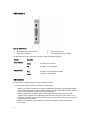
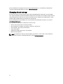
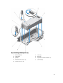
System overview
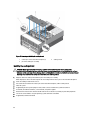
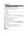
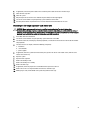
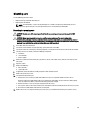
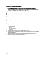
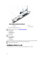
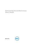
Your system includes up to four half-height server modules, two full-height server modules, or a mix of the server
module types. The server modules are specifically configured for the PowerEdge VRTX enclosure, and can be identified
by a label marked PCIe on the server module.
Figure 1. Identifying a server module configured for the PowerEdge VRTX enclosure
1.
PCIe label on the server module
3.
PowerEdge VRTX enclosure
2.
server module
If you install server modules that are not configured for the enclosure, an error message is displayed.
The enclosure supports power supplies, hard drives, Chassis Management Controllers (CMC), blower modules, and an
I/O module. These are shared resources for the server modules.
NOTE: To ensure proper operation and cooling, all bays in the enclosure must be populated at all times with either
a server module or with a blank. Similarly, all empty hard drive slots in the enclosure must be installed with harddrive blanks.
9
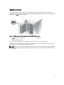
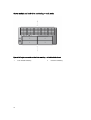
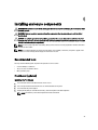
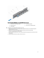
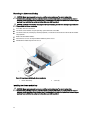
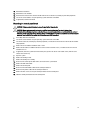
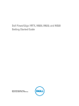
Server module and hard-drive numbering — tower mode
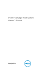
Figure 2. Half-height server module and hard-drive numbering — 2.5 inch hard-drive chassis
1.
10
server module numbering
2.
hard-drive numbering
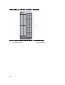
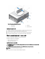
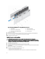
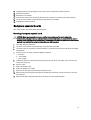
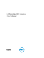
Figure 3. Full-height server module and hard-drive numbering — 2.5 inch hard-drive chassis
1.
server module numbering
2.
hard-drive numbering
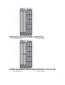
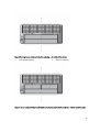
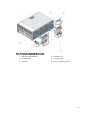
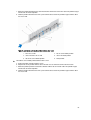
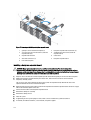
Figure 4. Server module (half-height and full-height server modules) and hard-drive numbering — 2.5 inch hard-drive chassis
1.
server module numbering
2.
hard-drive numbering
11
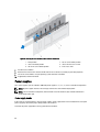
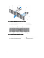
Figure 5. Half-height server module and hard-drive numbering — 3.5 inch hard-drive chassis
1.
server module numbering
2.
hard-drive numbering
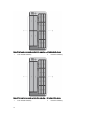
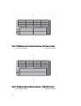
Figure 6. Full-height server module and hard-drive numbering — 3.5 inch hard-drive chassis
1.
12
server module numbering
2.
hard-drive numbering
Figure 7. Server module (half-height and full-height server modules) and hard-drive numbering — 3.5 inch hard-drive chassis
1.
server module numbering
2.
hard-drive numbering
13
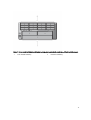
Server module and hard-drive numbering — rack mode
Figure 8. Half-height server module and hard-drive numbering — 2.5 inch hard-drive chassis
1.
14
server module numbering
2.
hard-drive numbering
Figure 9. Full-height server module and hard-drive numbering — 2.5 inch hard-drive chassis
1.
server module numbering
2.
hard-drive numbering
Figure 10. Server module (half-height and full-height server modules) and hard-drive numbering — 2.5 inch hard-drive chassis
15
Figure 11. Half-height server module and hard-drive numbering — 3.5 inch hard-drive chassis
1.
server module numbering
2.
hard-drive numbering
Figure 12. Full-height server module and hard-drive numbering — 3.5 inch hard-drive chassis
1.
16
server module numbering
2.
hard-drive numbering
Figure 13. Server module (half-height and full-height server modules) and hard-drive numbering — 3.5 inch hard-drive chassis
1.
server module numbering
2.
hard-drive numbering
17
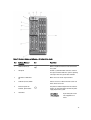
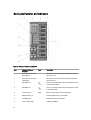
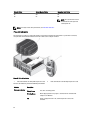
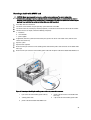
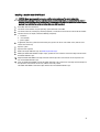
Front-panel features and indicators
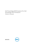
Figure 14. Front-panel features and indicators — 2.5 inch hard drive chassis
18
Figure 15. Front-panel features and indicators — 3.5 inch hard drive chassis
Item
Indicator, Button, or
Connector
Icon
Description
1
USB connectors (2)
Allows a keyboard and mouse to be connected to
the system.
2
LCD panel
Provides system information and status and error
messages to indicate when the system is operating
correctly or when the system needs attention.
3
LCD menu scroll buttons
(4)
Moves the cursor in one-step increments.
4
Selection ("check") button
Selects and saves an item on the LCD screen and
moves to the next screen.
5
Enclosure power-on
indicator, power button
The power-on indicator lights when the enclosure
power is on. The power button controls the power
supply output to the system.
6
Hard drives
2.5 inch hard
drive enclosure
Up to twenty five 2.5 inch
hot-swappable hard
drives.
19
Item
Indicator, Button, or
Connector
Icon
Description
3.5 inch hard
drive enclosure
Up to twelve 3.5 inch hotswappable hard drives.
7
Information tag
A slide-out label panel which allows you to record
system information such as Service Tag, NIC, MAC
address, the system electrical rating, and
Worldwide Regulatory Agency marks.
8
Optical drive (optional)
One optional SATA DVD-ROM drive or DVD+/-RW
drive.
9
Vents
Vents for the temperature sensor.
NOTE: To ensure proper cooling, ensure that
the vents are not blocked.
10
Video connector
Allows a monitor to be connected to the system.
11
Server modules
Up to four half-height server modules, or up to two
full-height server modules specifically configured
for the enclosure.
KVM features
•
Local KVM access can be remotely disabled on a per server module basis, using the server module iDRAC interface
(access is enabled by default).
•
One VGA connector — The KVM supports a video display resolution range from 640 × 480 at 60 Hz up to 1280 × 1024
× 65,000 colors (non-interlaced) at 75 Hz.
•
Two USB ports for keyboard and mouse.
•
The KVM provides access to the server modules. You can access one server module at a time using the LCD panel.
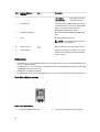
Hard-drive indicator patterns
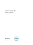
Figure 16. Hard-drive indicators
1.
20
hard-drive activity indicator (green)
2.
hard-drive status indicator (green and amber)
Drive-Status
Indicator Pattern
Condition
Blinks green two
times per second
Identifying drive or preparing for removal
Off
Drive ready for insertion or removal
NOTE: The drive status indicator remains off until all hard drives are initialized after the
system is turned on. Drives are not ready for insertion or removal during this time.
Blinks green, amber,
and off
Predicted drive failure
Blinks amber four
times per second
Drive failed
Blinks green slowly
Drive rebuilding
Steady green
Drive online
Blinks green three
Rebuild aborted
seconds, amber three
seconds, and off six
seconds
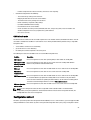
LCD module
You can use the LCD panel on the enclosure chassis to perform configuration and diagnostics, and to obtain status
information about the chassis and its contents.
Figure 17. LCD display
1.
LCD screen
3.
scroll buttons (4)
2.
selection ("check") button
LCD module features
The primary function of the LCD module is to provide real-time information on the health and status of the modules in the
enclosure.
LCD module features include:
•
A deployment setup that allows you to configure the CMC network settings during initial system setup.
21
•
Menus to configure the iDRAC in each server module.
•
Status information screens for each server module.
•
Status information screens for the modules installed in the back of the enclosure, including the I/O module, blower
modules, CMC, KVM, and power supplies.
•
An IP Summary screen listing the IP addresses of all components in the system.
•
Real time power consumption statistics, including high and low values, and average power consumption.
•
Ambient temperature values.
•
AC power information.
•
Critical failure alerts and warnings.
Using the LCD module menus
The LCD Setup menu displays a menu of items that can be configured.
Use the up and down arrow buttons to highlight an item in the menu or highlight the Back icon if you want to return to
the Main menu.
Press the center button to activate your selection.
Key
Action
Left and right arrows
Move between screens
Up arrow or down
arrow
Move to the previous or next option on a screen
Center button
Select and save an item and move to the next screen
Main menu
From the Main menu, you can navigate to one of the following screens:
Screen
Description
LCD Setup
Contains the options such as Language Setup, LCD Orientation, and the Default Screen.
KVM Mapping
Contains the options to map or unmap the KVM to the servers.
DVD Mapping
Contains the option to map or unmap the DVD drive on the chassis to the servers.
Enclosure
Displays status information for the chassis.
IP Summary
Displays IPv4 and IPv6 information about CMC and iDRAC.
LCD Setup menu
The LCD Setup Menu displays a menu of items that can be configured:
Language Setup
Select the language you want to use for LCD screen text and messages.
LCD Orientation
Select either Tower Mode or Rack Mode based on the installation orientation of the chassis.
Default Screen
Select the screen (Main menu, Front Status, Rear Status, Side Status, or Custom) that is
displayed when there is no activity on the LCD panel.
Use the up and down arrow buttons to highlight an item in the menu or highlight the Back icon if you want to return to
the Main menu.
Press the center button to activate your selection.
22
DVD mapping
From this screen, you can view the DVD to server mapping information, map another server to the DVD drive on the
chassis, or unmap the existing connection.
KVM Mapping menu
From this screen, you can view the KVM to server mapping information, map another server to the KVM, or unmap the
existing connection.
NOTE: The KVM does not map to the CMC.
Enclosure menu
From this screen, you can navigate to the following screens:
•
Front Status
•
Rear
•
Side
•
Enclosure status
Use the navigation buttons to highlight the desired item (highlight the Back icon to return to the Main menu) and press
the center button. The selected screen is displayed.
IP Summary menu
The IP Summary screen displays the IP information for CMC (IPv4 and IPv6) and iDRAC (IPv4 and IPv6) on each of the
installed servers.
Use the up and down arrow buttons to scroll through the list. Use the left and right arrow buttons to scroll selected
messages that are longer than the screen.
Use the up and down arrow buttons to select the Back icon and press the center button to return to the Enclosure menu.
23
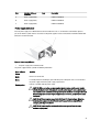
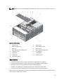
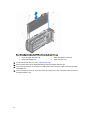
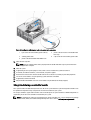
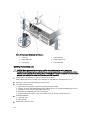
Back-panel features and indicators
Figure 18. Back-panel features and indicators
Item
Indicator, Button, or
Connector
1
PCIe expansion card slots
low-profile (5)
Allows you to connect up to five low-profile PCI Express
expansion cards.
2
PCIe expansion card slots
full height (3)
Allows you to connect up to three full-height PCI Express
expansion cards.
3
CMC GbE port 2
Connects the network cable from the management system
to the secondary CMC.
4
CMC GbE port 1
Connects the network cable from the management system
to the primary CMC.
5
Serial connector
DB-9 serial connector for CMC configuration.
6
Blower modules (4)
Provide cooling for the server modules.
7
I/O module ports
Network interface for I/O modules.
8
Power supply (PSU4)
1100 W or 1600 W AC
24
Icon
Description
Item
Indicator, Button, or
Connector
Icon
Description
9
Power supply (PSU3)
1100 W or 1600 W AC
10
Power supply (PSU1)
1100 W or 1600 W AC
11
Power supply (PSU2)
1100 W or 1600 W AC
Power supply indicators
Each AC power supply has an illuminated translucent handle that serves as an indicator to show whether power is
present or whether a power fault has occurred. The AC power supplies must be connected to a Power Distribution Unit
(PDU) or to an electrical outlet.
Figure 19. Power supply indicators
1.
AC power supply status indicator/handle
The power supply indicators provide the following information:
Power Indicator
Pattern
Condition
Not lit
Power is not connected.
Green
In standby mode, the handle lights green indicating that a valid power source is connected to
the power supply and that the power supply is operational.
Flashing amber
Indicates a problem with the power supply.
CAUTION: When correcting a power supply mismatch, replace only the power supply
with the flashing indicator. Swapping the opposite power supply to make a matched pair
can result in an error condition and unexpected system shutdown. To change from a High
Output configuration to a Low Output configuration or vice versa, you must power down
the system.
CAUTION: AC Power supplies support both 220 V and 110 V input voltages. When two
identical power supplies receive different input voltages, they can output different
wattages, and trigger a mismatch.
CAUTION: All power supplies used must be of the same type and have the same
maximum output power.
25
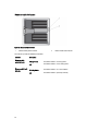
Blower module indicators
Figure 20. Blower module indicators
1.
blower module power indicator
2.
blower module fault indicator
The indicators provide the following information:
Indicator
Blower module
power indicator
Blower module fault
indicator
26
Description
Steady Green
The blower module is receiving power.
Off
The blower module is not receiving power.
Blinking Amber
The blower module is in a fault condition.
Off
The blower module is operating normally.
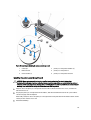
I/O module indicators
Figure 21. I/O module indicators
1.
power indicator
2.
status indicator
The indicators provide the following information:
Indicator
Power indicator
Status indicator
Description
Green
The I/O module is operating normally.
Off
The I/O module is powered off.
Blue
The I/O module is operating normally.
Blinking Blue
The CMC is identifying the I/O module.
Blinking Amber
The I/O module is in a fault condition.
Off
The I/O module is powered off, or booting is in progress.
For more information, see the I/O module documentation at dell.com/poweredgemanuals.
27
CMC indicators
Figure 22. CMC indicators
1.
status/identification indicator (CMC 1)
2.
power indicator (CMC 1)
3.
power indicator (CMC 2)
4.
status/identification indicator (CMC 2)
The CMC indicators on the back panel of the enclosure provide the following information:
Indicator
Power indicator
Status indicator
Description
Green
The CMC is receiving power.
Off
The CMC is not receiving power.
Blue
The CMC is active and operating normally.
Amber
The CMC is in fault condition.
CMC features
The CMC provides the following multiple systems management functions:
•
28
Enclosure-level real-time automatic power and thermal management:
–
Monitors system power requirements and supports the optional Dynamic Power Supply Engagement (DPSE)
mode. The DPSE mode improves power efficiency by allowing the CMC to dynamically place power supplies in
standby mode, depending on the load and redundancy requirements.
–
Reports real-time power consumption, which includes logging high and low points with a time stamp.
–
Supports setting an optional enclosure Maximum Power Limit, which either alerts or takes actions, such as
throttling server modules and/or preventing the power up of new server modules to keep the enclosure under
the defined maximum power limit.
–
Monitors and automatically controls cooling fans based on actual ambient and internal temperature
measurements.
–
•
Provides comprehensive enclosure inventory and status or error reporting.
Centralized configuration of the following:
–
The shared storage settings of the enclosure.
–
Mapping of add-in PCIe cards to the server modules.
–
The network and security settings of the enclosure.
–
Power redundancy and power ceiling settings.
–
I/O module and iDRAC network settings.
–
First boot device on the server modules.
–
Checks I/O fabric consistency for the I/O module, PCIe slots, storage subsystem, and server modules and
disables components if necessary to protect the system hardware.
–
User access security.
CMC fail-safe mode
The VRTX enclosure enables the fail-safe mode to protect the server modules and the I/O module from failures. The failsafe mode is enabled when no CMC is in control of the chassis. During the CMC failover period or during a single CMC
management loss:
•
server modules cannot be accessed remotely
•
you cannot turn on a server module(s)
•
the cooling fans continue to operate at the same speed
The following are some of the conditions that can result in CMC management loss:
Condition
Description
CMC removal
Chassis management resumes after replacing CMC, or after failover to standby CMC.
CMC network cable
removal or network
connection loss
Chassis management resumes after the chassis fails over to the standby CMC. Network
failover is only enabled in redundant CMC mode.
CMC reset
Chassis management resumes after the CMC reboots or chassis fails over to the standby CMC.
CMC failover
command issued
Chassis management resumes after the chassis fails over to the standby CMC.
CMC firmware update Chassis management resumes after the CMC reboots or chassis fails over to the standby CMC.
It is recommended that you update the standby CMC first so that there is only one failover
event. For more information on updating the CMC firmware, see the Dell Chassis Management
Controller for Dell PowerEdge VRTX User’s Guide at dell.com/esmmanuals.
CMC error detection
and correction
Chassis management resumes after the CMC resets or chassis fails over to the standby CMC.
NOTE: You can configure the enclosure with a single CMC or with redundant CMCs. In redundant CMC
configurations, if the primary CMC loses communication with the enclosure or the management network, the
standby CMC takes over chassis management.
Configuration wizard
The CMC is preset for Dynamic Host Configuration Protocol (DHCP). To use a static IP address, you must toggle the CMC
setting from DHCP to a static address by either running the LCD configuration wizard, or by using a management station
29
and CLI commands. For more information, see the Dell Chassis Management Controller for Dell PowerEdge VRTX User’s
Guide at dell.com/esmmanuals.
To set up a network using the LCD configuration wizard:
1.
If the enclosure is off, press the enclosure power button to turn it on.
The LCD screen displays a series of initialization screens as it turns on. When it is ready, the Language Setup
screen is displayed.
2.
Select a language from the options in the dialog box.
The following message is displayed on the enclosure screen: Configure Enclosure?
3.
Press the center button to continue to the CMC Network Settings screen.
4.
Configure the CMC network settings for your network environment:
5.
•
Network speed
•
Duplex mode
•
Network mode (DHCP or static)
•
Static IP address, subnet mask, and gateway values (if static mode was selected)
• DNS settings
If required, configure the iDRAC network settings.
For more information about iDRAC, see the iDRAC User’s Guide at dell.com/support/manuals.
NOTE: The configuration wizard automatically configures each server module’s iDRAC internal network
interface if you do not choose to manually configure the iDRAC settings.
NOTE: You cannot set a static IP address for the iDRAC using the LCD configuration wizard. To set a static IP
address, use the CMC web-based interface or Remote Access Controller Administrator (RACADM).
6.
Review the settings on the Network Summary screen:
•
If the settings are correct, press the center button to close the configuration wizard and return to the Main
Menu.
•
If the settings are not correct, use the left arrow key to return to the screen for that setting and correct it.
After you complete the configuration wizard, the CMC is available on your network.
System messages
System messages related to the server modules in the enclosure may appear on the monitor screen to notify you of a
possible problem with a server module. For a detailed listing of these error messages, including possible causes and
solutions, see the server module documentation.
LCD messages
For a complete list of messages that are displayed on the front panel LCD screen, see the Dell PowerEdge VRTX Chassis
Management Controller Firmware Event Message Reference Guide at dell.com/esmmanuals.
30
Documentation matrix
The documentation matrix provides information on documents that you can refer to, for setting up and managing your
system.
To...
Refer to...
Install your system into a rack
Rack documentation included with your rack solution
Set up your system and know the system technical
specifications
Getting Started Guide
Set up and configure your system
Quick Start Reference Guide
Install the operating system
Operating system documentation at dell.com/
operatingsystemmanuals
Get an overview of the Dell Systems Management
offerings
Dell OpenManage Systems Management Overview Guide
at dell.com/openmanagemanuals
Install, configure, and use the Chassis Management
Controller (CMC)
CMC User’s Guide at dell.com/esmmanuals
Configure and log in to iDRAC, set up managed and
management system, know the iDRAC features and
troubleshoot using iDRAC
Integrated Dell Remote Access Controller User's Guide at
dell.com/esmmanuals
Know about the RACADM subcommands and supported
RACADM interfaces
RACADM Command Line Reference Guide for iDRAC and
CMC at dell.com/esmmanuals
Launch, enable and disable Lifecycle Controller, know the
features, use and troubleshoot Lifecycle Controller
Dell Lifecycle Controller User’s Guide at dell.com/
esmmanuals
Use Lifecycle Controller Remote Services
Dell Lifecycle Controller Remote Services Quick Start
Guide at dell.com/esmmanuals
Set up, use, and troubleshoot OpenManage Server
Administrator
Dell OpenManage Server Administrator User’s Guide at
dell.com/openmanagemanuals
Install, use and troubleshoot OpenManage Essentials
Dell OpenManage Essentials User’s Guide at dell.com/
openmanagemanuals
Know the system features, remove and install system
components, and troubleshoot components
Owner’s Manual at dell.com/poweredgemanuals
Know the server module features, remove and install
server module components, troubleshoot server module
components
Server module Owner’s Manual at dell.com/
poweredgemanuals
Know about I/O module features, configure the I/O module I/O module documentation at dell.com/poweredgemanuals
and additional I/O module information
Know the features of the storage controller cards, deploy
the cards, and manage the storage subsystem
Storage controller documentation at dell.com/
storagecontrollermanuals
See the event and error messages generated by the
system firmware and agents that monitor system
components
Dell Event and Error Messages Reference Guide at
dell.com/esmmanuals
31
Quick Resource Locator
Use the Quick Resource Locator (QRL) to get immediate access to system information and how-to videos. This can be
done by visiting dell.com/QRL or by scanning a model specific QR code located on your Dell PowerEdge system using
your smartphone. You can also access your system information and how-to videos by scanning the following QR code.
32
Initial system configuration
2
Before you begin
CAUTION: The enclosure power supplies must be connected to a PDU or to an electrical outlet. The power
supplies require a 100 V to 120 V or 200 V to 240 V power source. You can select only one AC power input, as the
system does not operate at both ranges simultaneously.
NOTE: Ensure that all the component software are upgraded to the latest versions. For information on the latest
supported firmware and driver versions, see the Drivers & Downloads link on dell.com/support/drivers, for your
system.
•
Your system supports server modules that are specifically configured for the enclosure, and can be identified by a
label marked PCIe on the server module. If you install server modules that are not configured for the enclosure, an
error message is displayed. For more information on configuring a server module for the enclosure, see Configuring
A Server Module.
•
Ensure that you have downloaded the latest BIOS on the server module(s) from dell.com/support.
•
Update all PCIe mezzanine card firmware and iDRAC firmware on the server module(s).
•
Download the latest version of CMC firmware from dell.com/support. Also, make sure that you have the Dell Systems
Management Tools and Documentation DVD that was included with your system.
•
If your network uses static addressing, you need the IP address, subnet mask, and gateway to configure the CMC
and other modules in the enclosure.
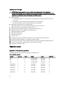
Initial setup sequence
CAUTION: To maintain optimum thermal conditions, ensure that there are no obstructions to airflow on the front
and back of the enclosure. The front and back of the enclosure must have at least 30 cm (12 inches) and 61 cm (24
inches) of unobstructed space respectively.
•
Unpack the enclosure and the server module(s) and identify each item. For more information, see the Getting Started
Guide and Rack Installation Guide at dell.com/poweredgemanuals.
•
The tower system has four feet on its bottom panel that can be extended outward to help properly stabilize the
system. You can also install the optional wheel assembly. For more information, see Installing The Wheel Assembly.
WARNING: Failure to extend the system feet outward poses the risk of having the system tip over, possibly
causing bodily injury or damage to the system.
CAUTION: Rolling the system on its wheels can cause vibrations that can damage the system.
•
1.
If you are using the optional rack configuration, assemble the rails and install the system in the rack following the
safety instructions and the rack installation instructions provided with your system. For more information on
converting the system to rack mode, see Converting The System From Tower Mode To Rack Mode.
Install the server module(s).
CAUTION: Do not turn on the server module(s) until you have configured the I/O module.
2.
Connect the network cable to the I/O module to provide network connection to the server.
33
NOTE: If you have a pass-through module installed in the enclosure, each server module requires its own
network cable.
3.
Connect the power supply units to a PDU or electrical outlet using the power cables.
4.
Optionally, connect the keyboard, video, and mouse to the enclosure.
5.
Press the power button on the enclosure's front panel.
Alternatively, you can also turn on the chassis from the CMC Web interface after completing step 7.
6.
Using the LCD panel on the front of the system, provide CMC with a static IP address or configure it for DHCP.
The LCD configuration wizard allows you to quickly configure the CMC and iDRAC management interfaces and
manage the enclosure remotely. You can also use a management station and the RACADM CLI to configure the
CMC.
NOTE: For a detailed description on configuring the CMC settings, see the Dell Chassis Management
Controller for Dell PowerEdge VRTX User’s Guide at dell.com/esmmanuals.
7.
Connect to the CMC IP address through the Web browser using the default logon credentials.
The default user name is root and password is calvin.
8.
Provide each iDRAC with an IP address in the CMC Web interface and enable the LAN and IPMI interface.
NOTE: iDRAC LAN interface on some server modules are disabled by default.
9.
Provide the switch module with an IP address in the CMC Web interface.
NOTE: No configuration is required if you are installing a pass-through module.
10. Connect to each iDRAC through the Web browser and provide final configuration of iDRAC.
The default user name is root and password is calvin.
11. Connect to the switch module through the Web browser and provide final configuration of the switch module.
NOTE: No configuration is required if you are installing a pass-through module.
12. Turn on the server modules and install the operating system.
Logging in to the CMC
You can perform the initial network configuration of CMC before or after CMC has an IP address.
You can log in to CMC as a CMC local user, as a Microsoft Active Directory user, or as an LDAP user. You can also log in
using Single Sign-On or Smart Card.
For more information on managing the chassis and configuring the settings, see the Dell Chassis Management Controller
for Dell PowerEdge VRTX User’s Guide at dell.com/esmmanuals.
34
Configuring enclosure components
3
Fabric A
Fabric A refers to the Ethernet connectivity provided to the server modules by the I/O module installed at the back of the
PowerEdge VRTX enclosure.
Fabric A provides internal connection to four lanes per server module for a maximum of 16 lanes. The number of external
connections are based on the I/O module installed. The R1-2401 switch and R1-PT pass-through module provide a
maximum of eight RJ-45 1 GbE ports. The R1-2210 switch module provides a maximum of two RJ-45 1 GbE ports and four
SFP+ 10 GbE ports.
The following conditions apply:
•
Dell PowerEdge M520 server module disables ports 3 and 4 when a pass-through module is installed. However, if
you install a switch module, all four network ports on Fabric A are utilized.
•
Fabric A in PowerEdge M620 is a 10 GbE capable interface. Fabric A operates at 1 GbE to support a pass-through or
the R1-2401 switch module, and at 10 GbE to support the R1-2210 switch module.
•
Fabric A in PowerEdge M820 is a 10 GbE capable interface. Fabric A operates at 1 GbE to support a pass-through or
the R1-2401 switch module, and at 10 GbE to support the R1-2210 switch module.
For information on the supported I/O modules, see Supported I/O Modules.
Fabrics B and C
Fabrics B and C refer to the PCIe connections between the server modules and the VRTX enclosure. These fabrics
support PCIe mezzanine cards installed in the server modules. The enclosure has two PCIe switches (Fabric B and
Fabric C switches) integrated on the system board to connect the server modules to the Shared PoweEdge RAID
Controller (PERC) card slots and eight PCIe expansion-card slots on the enclosure.
NOTE: To locate the Shared PERC card slots and the PCIe slots on the enclosure system board, see System Board
Connectors.
The PCIe switch mapping to the PCIe card slots is dependent on the firmware and the software license installed on the
system. For more information on mapping PCIe slots, see Mapping PCIe Expansion Slots.
NOTE: PCIe NICs systems management is not supported on Fabrics B and C.
I/O module and PCIe mezzanine card configuration guidelines
•
Fabric A supports an Ethernet switch or a pass-through module.
•
To enable switch configuration before imaging the server modules, the I/O module must be allowed to power-up
before the server modules are turned on.
•
Each half-height server module installed in the PowerEdge VRTX enclosure supports two PCIe mezzanine cards in
Fabric B and Fabric C slots. Each full-height server module supports four PCIe mezzanine cards in the two Fabric B
and two Fabric C slots. To locate the Fabric B and Fabric C slots, see the server module Owner's Manual at dell.com/
poweredgemanuals. The PCIe mezzanine cards are mapped to the PCIe expansion slots on the enclosure. For more
information, see Mapping PCIe Expansion Slots.
35
NOTE: Only PCIe mezzanine cards can be installed in Fabrics B and C of the server modules. Non-PCIe
mezzanine cards such as Ethernet, Fibre Channel, or InfiniBand mezzanine cards are not supported. If you
install non-PCIe mezzanine cards on the server modules, an error message is displayed on the LCD screen of
the enclosure.
NOTE: Single PCIe mezzanine card operation is not supported.
Supported I/O modules
The enclosure supports a switch or a pass-through module. The maximum Ethernet pass-through for a pass-through
module is eight lanes. A 1 Gb switch module can accept up to 16 lanes from Fabric A and output up to eight lanes to the
external ports. A 10 Gb switch module can accept up to 16 lanes from Fabric A and output six lanes to external ports
(four 10 GbE SFP+ ports and two 1 GbE RJ-45 ports).
The enclosure supports the following I/O modules:
•
Dell PowerEdge VRTX 1 Gb R1-PT pass-through module
•
Dell PowerEdge VRTX 1 Gb R1-2401 switch module
•
Dell PowerEdge VRTX 10 Gb R1-2210 switch module
NOTE: For more information on the I/O modules, see the I/O module documentation at dell.com/
poweredgemanuals.
Configuring network settings for the I/O module
You can specify the network settings for the interface used to manage the I/O module.
Before configuring the network settings for the I/O module, make sure the I/O module is turned on.
To configure the network setting, you must have Administrator privileges for Fabric A to configure the I/O module in
Group A.
You can configure the network settings using the following:
•
CMC web interface
•
RACADM
For more information on configuring the network settings, see the Dell Chassis Management Controller for Dell
PowerEdge VRTX User’s Guide at dell.com/esmmanuals.
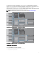
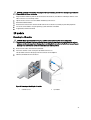
Mapping PCIe expansion slots
The enclosure has two PCIe switches integrated on the system board which map the Shared PERC storage slots and
PCIe expansion slots to the PCIe mezzanine cards on the server modules.
NOTE: Before mapping or unmapping a PCIe device, the server module must be turned off.
NOTE: The PCIe switch mapping is controlled by the firmware and depends on the software license installed on
the system:
•
With base licensing, each server module can be mapped to a maximum of two PCIe slots.
•
With the advanced licensing, a server module can map all available PCIe slots.
•
Default factory configuration has all PCIe slots unmapped.
For more information on PCIe slot configuration licensing, see the Dell Chassis Management Controller for Dell
PowerEdge VRTX User’s Guide at dell.com/esmmanuals.
36
The switches map the mezzanine cards to the PCIe slots on the enclosure's system board. There are five PCIe low
profile slots on the system board and three full-height, full-length PCIe slots on the PCIe riser. All the PCIe slots can be
mapped to the PCIe mezzanine cards on the server modules to provide I/O expansion for the system:
PCIe mezzanine Fabric B and Fabric C cards on each server module are mapped to the PCIe switches which further map
to the PCIe slots and the Shared PERC slots on the enclosure's system board.
NOTE: For information on the specifications of the supported PCIe cards, see Technical Specifications.
Figure 23. Mapping PCIe expansion slots — half-height server modules
Figure 24. Mapping PCIe expansion slots — full-height server modules
Managing PCIe slots
You can do the following using the CMC web interface:
•
View the status of both individual and all PCIe slots in the chassis.
•
Assign PCIe slots to server modules.
37
For more information on managing the PCIe slots using the CMC web interface, see the Dell Chassis Management
Controller for Dell PowerEdge VRTX User’s Guide at dell.com/esmmanuals.
Managing chassis storage
The enclosure provides shared storage with single or dual Shared PERC/Expander configurations. The Shared PERC
cards support Single Root Input Output Virtualization (SR-IOV) feature and enable the server modules to map to the local
storage through the PCIe switches on the enclosure system board. A server module can be mapped to either a single
Virtual Disk (VD) or multiple VDs that are located on the shared storage.
For more information on the Shared PERC cards, see the Dell Shared PowerEdge RAID Controller 8 User’s Guide at
dell.com/poweredgemanuals.
You can perform the following tasks related to the enclosure storage:
•
View the status of physical disks and storage controllers
•
View the properties of controllers, physical disks, virtual disks, and enclosures
•
Set up controllers, physical disks, and virtual disks
•
Assign virtual adapters
•
Troubleshoot controller, physical disks, and virtual disks
•
Update storage components
NOTE: For information on setting up storage controllers, physical disks, and virtual disks, see the Dell Chassis
Management Controller for PowerEdge VRTX User’s Guide at dell.com/esmmanuals.
38
Installing enclosure components
4
WARNING: Whenever you need to lift the system, get others to assist you. To avoid injury, do not attempt to lift the
system by yourself.
WARNING: Exercise care when removing or installing components when the system is on, to avoid the risk of
electric shock.
CAUTION: To maintain optimum thermal conditions, ensure that there are no obstructions to airflow on the front
and back of the enclosure. The front and back of the enclosure must have at least 30 cm (12 inches) and 61 cm (24
inches) of unobstructed space respectively.
NOTE: To ensure proper operation and cooling, all bays in the enclosure must be populated at all times with either
a module or with a blank.
NOTE: It is recommended that you remove the front bezel, server modules, hard drives, and power supplies from
the chassis to reduce weight, before laying the enclosure on its side.
Recommended tools
You may need the following items to perform the procedures in this section:
•
#1 and #2 Phillips screwdrivers
•
T6, T8, T10, T15, and T20 Torx drivers
•
Wrist grounding strap
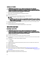
Front bezel (optional)
Installing the front bezel
1.
Insert the bezel tabs into the bezel tab slots in the chassis.
2.
Press the top end of the bezel into the chassis until the bezel locks into place.
3.
Insert the bezel key in the keylock.
4.
Keeping the keylock pressed with the bezel key, rotate the keylock to the locked position.
NOTE: The bezel key can be found taped to the inside of the bezel.
39
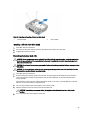
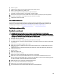
Figure 25. Removing and installing the front bezel
1.
release tab
2.
keylock
3.
front bezel
4.
bezel tabs
Removing the front bezel
1.
Insert the bezel key in the keylock.
2.
Keeping the keylock pressed with the bezel key, rotate the keylock to the unlocked position.
3.
Press the release tab at the top of the bezel toward the right.
4.
Move the top end of the bezel away from the system.
5.
Unhook the bezel tabs from the slots on the front of the chassis.
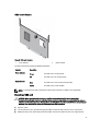
System feet—tower mode
The system feet provide stability to the system in the tower mode.
Removing the system feet
1.
To reduce the chassis weight, remove the following (if required):
a.
b.
c.
d.
Front bezel (if installed)
Hard drives. See Removing A Hot-Swap Hard Drive.
Server modules. See Removing A Server Module.
Power supplies. See Removing A Power Supply.
2.
Rotate the system feet inward.
3.
Lay the enclosure on its side on a flat, stable surface with the cover release latch side on top.
4.
Remove the screws securing the system feet to the system base cover.
40
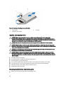
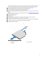
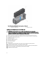
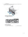
Figure 26. Removing and installing the system feet
1.
system feet (4)
2.
screws (4)
3.
screw holes (4)
4.
system base cover
Installing the system feet
1.
Align the screw holes on the system feet with the screw holes on the system base cover.
2.
Install the screws to secure the system feet to the system base cover.
3.
Place the enclosure upright on a flat, stable surface and rotate the system feet outward.
4.
If removed, reinstall the hard drives, server modules, power supplies, and front bezel.
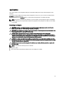
Wheel assembly (optional)—tower mode
The wheel assembly provides mobility to the system in the tower mode.
The wheel assembly consists of the following:
•
Wheel assembly units (front and back)
•
Power cable retention bracket
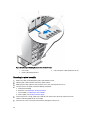
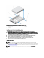
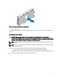
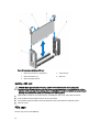
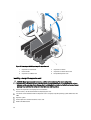
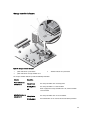
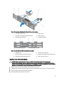
Installing the wheel assembly
WARNING: Whenever you need to lift the system, get others to assist you. To avoid injury, do not attempt to lift the
system by yourself.
CAUTION: Rolling the system on its wheels can cause vibrations that can damage the system.
NOTE: The front and back wheel plates are labeled.
1.
To reduce the chassis weight, remove the following (if required):
41
a.
b.
c.
d.
Front bezel (if installed)
Hard drives. See Removing A Hot-Swap Hard Drive.
Server modules. See Removing A Server Module.
Power supplies. See Removing A Power Supply.
2.
Rotate the system feet inward and lay the enclosure on its side on a sturdy, stable surface with the cover release
latch side on top, and the base of the enclosure extending slightly off the surface edge.
3.
Tilting the front wheel plate toward the hooks on the system base cover, align the metal stand on the wheel plate
with the hooks.
4.
Insert the metal stand on the front wheel plate into the hooks until firmly seated.
5.
Lower the other end of the front wheel plate to the chassis base and align the slot on the wheel plate with the tab
on the system base cover.
6.
Tighten the screw on the front wheel plate to secure it to the system base cover.
7.
Tilting the back wheel plate toward the hooks on the system base cover, align the metal stand on the wheel plate
with the hooks.
8.
Insert the metal stand on the back wheel plate into the hooks until firmly seated.
9.
Lower the other end of the back wheel plate to the chassis base and align the slot on the wheel plate with the tab
on the system base cover.
10. Tighten the screw on the back wheel plate to secure it to the system base cover.
11. Place the enclosure upright on a sturdy, stable surface.
12. If removed, reinstall the hard drives, server modules, power supplies, and front bezel.
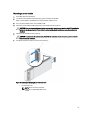
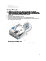
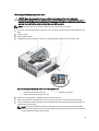
13. Align the tabs on the power cable retention bracket with the slots on the back end of the chassis base, below the
power supply bay.
NOTE: Place the enclosure in the upright position before installing the power cable retention bracket.
14. Insert the power cable retention bracket into the slots and slide the bracket to the left to lock it.
15. Route the power supply cables through the power cable retention bracket.
42
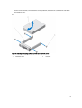
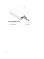
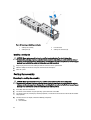
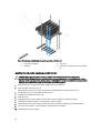
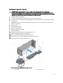
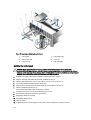
Figure 27. Removing and installing the wheel assembly
1.
hooks for the metal stands (4)
2.
metal stands (2)
3.
back wheel plate
4.
front wheel plate
5.
screws (2)
6.
tabs on system base cover (4)
43
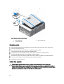
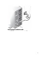
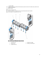
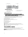
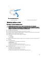
Figure 28. Removing and installing the power cable retention bracket
1.
chassis slots
3.
power cable retention bracket
2.
tabs on the power cable retention bracket (2)
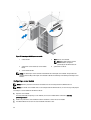
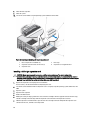
Removing the wheel assembly
1.
Remove any cables routed through the power cable retention bracket.
2.
Slide the power cable retention bracket to the right to unlock it.
3.
Holding it by the edges, pull the bracket out of the chassis slots and away from the chassis.
4.
To reduce the chassis weight, remove the following (if required):
a.
b.
c.
d.
Front bezel (if installed)
Hard drives. See Removing A Hot-Swap Hard Drive.
Server modules. See Removing A Server Module.
Power supplies. See Removing A Power Supply.
5.
Lay the enclosure on a sturdy, stable surface with the cover release latch side on top, and the base of the
enclosure extending slightly off the surface edge.
6.
Loosen the two screws securing the front and back wheel plates to the chassis.
44
7.
Remove the metal stands on the front and back wheel plates from the hooks on the system base cover.
8.
Remove the front and back wheel plates away from the chassis base.
9.
Place the enclosure upright on a sturdy, stable surface and rotate the system feet outward.
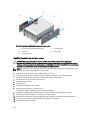
Removing and installing the system cover
WARNING: Whenever you need to lift the system, get others to assist you. To avoid injury, do not attempt to lift the
system by yourself.
WARNING: Installing or removing the system cover when the system is on may expose you to a risk of electric
shock.
CAUTION: Many repairs may only be done by a certified service technician. You should only perform
troubleshooting and simple repairs as authorized in your product documentation, or as directed by the online or
telephone service and support team. Damage due to servicing that is not authorized by Dell is not covered by your
warranty. Read and follow the safety instructions that came with the product.
CAUTION: Do not operate the system without the cover for a duration exceeding five minutes.
Opening the system
CAUTION: Installing the feet on a standalone tower system is necessary to provide a stable foundation for the
system. Failure to install the feet poses the risk of having the system tip over, possibly causing damage to the
system or bodily injury.
NOTE: It is recommended that you always use a static mat and static strap while working on components inside
the system.
NOTE: To replace hot-swappable components inside the enclosure, you do not need to turn off the enclosure or
lay it on its side, when opening the system.
1.
If installed, remove the front bezel.
2.
Turn off the server modules using the operating system commands or the CMC.
3.
Turn off the enclosure and attached peripherals, and disconnect the enclosure from the electrical outlet.
4.
To reduce the chassis weight, remove the following (if required):
a. Hard drives. See Removing A Hot-Swap Hard Drive.
b. Server modules. See Removing A Server Module.
c. Power supplies. See Removing A Power Supply.
5.
If applicable, rotate the system feet inward and lay the system on its side on a flat stable surface, with the cover
release latch side on top.
NOTE: For systems with the wheel assembly installed, ensure that you lay the system on a sturdy surface
with the wheel assembly extending off the edge of the surface.
6.
Rotate the latch release lock counter clockwise to the unlocked position.
7.
Press the cover release latch and lift the cover away from the system.
45
Figure 29. Opening and closing the system
1.
latch release lock
3.
system side cover
2.
cover release latch
Closing the system
1.
Place the bottom edge of the cover, opposite from the cover release latch, into the slots in the system chassis.
2.
Lower the cover into the chassis.
3.
Press the latch end of the cover into the chassis until the latch locks into place.
4.
Turn the cover latch release lock clockwise to the locked position.
5.
If applicable, place the system upright on a flat, stable surface and rotate the system feet outward.
6.
If removed, reinstall the hard drives, server modules, and power supplies.
7.
Reconnect the enclosure to its electrical outlet and turn the enclosure on, including any attached peripherals.
8.
Turn on the server modules using the operating system commands or the CMC.
9.
If applicable, install the front bezel.
Inside the system
CAUTION: Many repairs may only be done by a certified service technician. You should only perform
troubleshooting and simple repairs as authorized in your product documentation, or as directed by the online or
telephone service and support team. Damage due to servicing that is not authorized by Dell is not covered by your
warranty. Read and follow the safety instructions that came with the product.
46
NOTE: Components that are hot-swappable are marked orange and touch points on the components are marked
blue.
Figure 30. Inside the system
1.
cooling fans (6)
2.
cooling shroud
3.
CMC card indicators (2)
4.
chassis intrusion switch
5.
PCIe cage
6.
CMC cards (2)
7.
low profile expansion-card divider unit
8.
power distribution board bracket
9.
system base cover
10.
hard drives (25)
11.
optical drive
12.
server modules
13.
control panel
14.
mounting ears (2)
15.
hard-drive backplane
Hard drives
•
The 3.5 inch hard-drive enclosure supports up to twelve hot-swappable 3.5 inch hard drives.
•
The 2.5 inch hard-drive enclosure supports up to twenty-five hot-swappable 2.5 inch hard drives.
•
All hard drives connect to the system board through the hard-drive backplane.
•
Hard drives are supplied in hot-swappable hard-drive carriers that fit in the hard-drive slots.
•
Use only hard drives that have been tested and approved for use with the hard-drive backplane.
When you format a hard drive, allow enough time for the formatting to be completed. Be aware that high-capacity hard
drives can take a number of hours to format.
47
NOTE: The following procedures apply to the hard drives in the enclosure. For server module-specific hard drives,
see the server module's Owner's Manual at dell.com/poweredgemanuals.
Removing a 2.5 inch hard-drive blank
CAUTION: To maintain proper system cooling, all empty hard-drive slots must have hard-drive blanks installed.
1.
If installed, remove the front bezel.
2.
Press the release button and slide the hard-drive blank out until it is free of the hard-drive slot.
Figure 31. Removing and Installing a 2.5 Inch Hard-Drive Blank
1.
hard-drive blank
2.
release button
Installing A 2.5 Inch Hard-Drive Blank
1.
If installed, remove the front bezel.
2.
Insert the hard-drive blank into the hard-drive slot until the release button clicks into place.
3.
If applicable, install the front bezel.
Removing a 3.5 inch hard-drive blank
CAUTION: To maintain proper system cooling, all empty hard-drive slots must have drive blanks installed.
1.
If installed, remove the front bezel.
2.
Grasp the front of the hard-drive blank, press the release button and slide the blank out until it is free of the harddrive slot.
48
Figure 32. Removing and installing a 3.5 inch hard-drive blank
1.
hard-drive blank
2.
release button
Installing a 3.5 inch hard-drive blank
1.
If installed, remove the front bezel.
2.
Insert the hard-drive blank into the hard-drive slot until the release button clicks into place.
3.
If applicable, install the front bezel.
Removing a hot-swap hard drive
CAUTION: Before attempting to remove or install a hard drive while the system is running, see the documentation
for the storage controller card to ensure that the host adapter is configured correctly to support hot-swap hard
drive removal and insertion.
CAUTION: Do not turn off or reboot your system while the hard drive is being formatted. Doing so can cause a hard
drive failure.
CAUTION: To prevent data loss, ensure that your operating system supports hot-swap drive installation. See the
documentation supplied with your operating system.
1.
If installed, remove the front bezel.
2.
From the management software, prepare the hard drive for removal. Wait until the indicators on the hard-drive
carrier signal that the hard drive can be removed safely. For more information, see the documentation for the
storage controller.
If the hard drive is online, the green activity/fault indicator flashes as the drive is turned off. When the hard-drive
indicators are off, the hard drive is ready for removal.
3.
Press the release button to open the hard-drive carrier release handle.
4.
Slide the hard-drive carrier out until it is free of the hard-drive slot.
CAUTION: To maintain proper system cooling, all empty hard-drive slots must have hard-drive blanks
installed.
5.
Insert a hard-drive blank in the empty hard-drive slot.
49
Figure 33. Removing and installing a hot-swap hard drive
1.
release button
3.
hard-drive carrier handle
2.
hard drive
Installing a hot-swap hard drive
CAUTION: Many repairs may only be done by a certified service technician. You should only perform
troubleshooting and simple repairs as authorized in your product documentation, or as directed by the online or
telephone service and support team. Damage due to servicing that is not authorized by Dell is not covered by your
warranty. Read and follow the safety instructions that came with the product.
CAUTION: Use only hard drives that have been tested and approved for use with the hard-drive backplane.
CAUTION: When installing a hard drive, ensure that the adjacent drives are installed properly. Inserting a harddrive carrier and attempting to lock its handle next to a partially installed carrier can damage the partially installed
carrier's shield spring and make it unusable.
CAUTION: To prevent data loss, ensure that your operating system supports hot-swap drive installation. See the
documentation supplied with your operating system.
CAUTION: When a replacement hot-swappable hard drive is installed and the system is powered on, the hard
drive automatically begins to rebuild. Make absolutely sure that the replacement hard drive is blank or contains
data that you wish to have over-written. Any data on the replacement hard drive is immediately lost after the hard
drive is installed.
1.
If installed, remove the front bezel.
2.
If a hard-drive blank is installed in the hard-drive slot, remove it.
3.
Install a hard drive in the hard-drive carrier.
4.
Press the release button on the front of the hard-drive carrier and open the hard-drive carrier handle.
5.
Insert the hard-drive carrier into the hard-drive slot until the carrier connects with the backplane.
6.
Close the hard-drive carrier handle to lock the hard drive in place.
7.
If applicable, install the front bezel.
Removing a hard drive from a hard-drive carrier
1.
50
Remove the screws from the slide rails on the hard-drive carrier.
For the 2.5 inch hard drive, turn the hard-drive carrier upside down, and remove the screws from the side rails on
the hard-drive carrier.
2.
Lift the hard drive out of the hard-drive carrier.
Figure 34. Removing and installing a 2.5 inch hard drive into a hard-drive carrier
1.
hard-drive carrier
3.
screws (4)
2.
hard drive
51
Figure 35. Removing and installing a 3.5 inch hard drive into a hard-drive carrier
1.
hard-drive carrier
3.
screws (4)
2.
hard drive
Installing a hard drive into a hard-drive carrier
CAUTION: Many repairs may only be done by a certified service technician. You should only perform
troubleshooting and simple repairs as authorized in your product documentation, or as directed by the online or
telephone service and support team. Damage due to servicing that is not authorized by Dell is not covered by your
warranty. Read and follow the safety instructions that came with the product.
1.
Insert the hard drive into the hard-drive carrier with the connector end of the hard drive toward the back.
2.
Align the screw holes on the hard drive with the set of screw holes on the hard-drive carrier.
When aligned correctly, the back of the hard drive is flush with the back of the hard-drive carrier.
3.
Attach the screws to secure the hard drive to the hard-drive carrier.
Server modules
NOTE: Your system supports server modules that are specifically configured for the enclosure, and can be
identified by a label marked PCIe on the server module. If you install server modules that are not configured for the
enclosure, an error message is displayed. For more information on configuring a server module for the enclosure,
see Configuring A Server Module.
NOTE: Ensure that you have downloaded the latest BIOS on the server module(s) from dell.com/support.
52
Removing a server module
1.
If installed, remove the front bezel.
2.
Turn off the server module using the operating system commands or the CMC.
When a server module is powered off, its front-panel power indicator is off.
3.
Press the release button on the server module handle.
4.
Pull out the server module handle to unlock the server module from the enclosure.
CAUTION: If you are permanently removing the server module, install a server module blank(s). Operating the
system for an extended period of time without a server module blank installed can cause the enclosure to
overheat.
5.
Slide the server module out of the enclosure.
CAUTION: To protect the I/O connector pins, install the I/O connector covers every time a server module is
removed from the enclosure.
6.
Install the I/O connector cover(s) over the I/O connector(s).
Figure 36. Removing and installing the I/O connector cover
1.
I/O connector cover
NOTE: There are two I/O connector
covers on the PowerEdge M820 server
module.
53
Figure 37. Removing and installing a server module
1.
release button
2.
PCIe label on server module
NOTE: This label indicates that the
server module is configured
specifically for the VRTX enclosure.
3.
guide rail on server module (or server module
blank)
5.
server module handle
4.
guide rail on enclosure
NOTE: The above figure shows removal and installation of a half-height server module. The procedure for
removing and installing a full-height server module is identical to removing and installing a half-height server
module.
Configuring a server module
NOTE: Follow this procedure to install server modules that are not configured for the VRTX enclosure.
NOTE: If you install server modules that are not configured for the VRTX enclosure, an error message is displayed.
To configure a server module for the VRTX enclosure:
1.
Open the server module.
For more information on opening a server module, see the server module Owner's Manual at dell.com/
poweredgemanuals.
2.
Remove any mezzanine cards installed in Fabric B and Fabric C slots of the server module.
3.
Install PCIe Mezzanine cards in the vacant Fabric B and Fabric C slots.
54
For more information on installing the PCIe Mezzanine cards, see the server module Owner's Manual at dell.com/
poweredgemanuals.
4.
Ensure that no tools or parts are left inside the server module.
5.
Slide the cover on the server module until it clicks into position.
A properly seated cover is flush with the surface of the server module chassis.
6.
Install the latest iDRAC Enterprise license. For more information, see the iDRAC7 User's Guide, at dell.com/
esmmanuals.
Installing a server module
Your system supports server modules that are specifically configured for the PowerEdge VRTX enclosure, and can be
identified by a label marked PCIe on the top of the server module.
NOTE: To install full-height server module(s), you must remove the server module partitions. For more information,
see Removing The Server Module Partitions.
1.
If you are installing a new server module, remove the plastic cover(s) from the I/O connector(s) and save for future
use.
2.
If applicable, configure the server module. For more information, see Configuring A Server Module.
3.
Orient the server module so that the module handle is on the left side of the server module.
4.
Align the server module with the server module slot and guide rails on the enclosure.
5.
Using both hands, slide the server module into the enclosure until the module release handle engages and locks
the server module in place.
6.
If applicable, reinstall the front bezel.
Server module partitions
You must remove the server module partitions to install full-height server modules in the PowerEdge VRTX enclosure.
You must install the server module partition to:
•
Install half-height server modules in the enclosure.
•
Install server module blanks.
55
Figure 38. Server module partitions
1.
metal partition
2.
outer chassis wall
3.
server module partition between Slots 1 and 3
4.
server module partition between Slots 2 and 4
5.
inner chassis wall
Removing the server module partitions
CAUTION: Many repairs may only be done by a certified service technician. You should only perform
troubleshooting and simple repairs as authorized in your product documentation, or as directed by the online or
telephone service and support team. Damage due to servicing that is not authorized by Dell is not covered by your
warranty. Read and follow the safety instructions that came with the product.
NOTE: You must remove the server module partitions to install full-height server modules.
1.
If installed, remove the front bezel.
2.
Turn off the server modules using the operating system commands or the CMC.
3.
Turn off the enclosure, including any attached peripherals, and disconnect the enclosure from the electrical outlet.
4.
Remove the server modules or server module blanks.
5.
To remove the server module partition between Slots 1 and 3:
a. Hold the release tab on the server module partition and pull it out from the chassis wall to disengage the
locking tab from the slot on the chassis wall.
b. Holding the release tab, pull the partition toward the front of the system until it stops sliding.
The tabs on the partition move to unlock position.
c. Rotate the partition upward in the counter-clockwise direction to disengage the tabs from the slots on the metal
partition.
d. Slide the partition out from the system, and save for future use.
56
Figure 39. Removing and installing the server module partition between slots 1 and 3
6.
1.
locking tab on server module partition
2.
server module partition
3.
outer chassis wall
4.
tabs on the server module partition
5.
metal partition
To remove the server module partition between Slots 2 and 4:
a. Hold the release tab on the server module partition and pull it out from the chassis wall to disengage the
locking tab from the chassis slot.
b. Holding the release tab, pull the partition toward the front of the system until it stops sliding.
The tabs on the partition move to unlock position.
c. Rotate the partition downward in the counter-clockwise direction to disengage the tabs from the slots on the
metal partition.
d. Slide the partition out from the system, and save for future use.
57
Figure 40. Removing and installing the server module partition between slots 2 and 4
7.
1.
metal partition
2.
server module partition
3.
tabs on the server module partition
4.
slots on the inner chassis wall
5.
locking tab on server module partition
6.
inner chassis wall
Install the server modules.
8.
Reconnect the enclosure to the electrical outlet and turn the enclosure on, including any attached peripherals.
9.
Turn on the server modules using the operating system commands or the CMC.
10. If applicable, install the front bezel.
Installing the server module partitions
CAUTION: Many repairs may only be done by a certified service technician. You should only perform
troubleshooting and simple repairs as authorized in your product documentation, or as directed by the online or
telephone service and support team. Damage due to servicing that is not authorized by Dell is not covered by your
warranty. Read and follow the safety instructions that came with the product.
1.
If installed, remove the front bezel.
2.
Turn off the server modules using the operating system commands or the CMC.
3.
Turn off the enclosure, including any attached peripherals, and disconnect the enclosure from the electrical outlet
and peripherals.
4.
Remove the server modules or server module blanks.
5.
To install the server module partition between Slots 1 and 3:
a. Angle the partition and slide it into the chassis.
b. Align the tabs on the partition with the slots on the outer chassis wall and insert the tabs into the slots.
58
c. Rotate the partition downward in the clockwise direction until the tabs on the other side of the partition engage
with the slots on the metal partition.
d. Slide the partition toward the back of the system until the release tab on the partition engages with the slot on
the chassis wall.
Figure 41. Installing the server module partition between slots 1 and 3
6.
1. outer chassis wall
2. tabs on server module partition
3. slots on the outer chassis wall
4. slots on the metal partition
5. tabs on the server module partition
6. metal partition
To install the server module partition between Slots 2 and 4:
a. Angle the partition and slide it into the chassis.
b. Align the tabs on the partition with the slots on the inner chassis wall and insert the tabs into the slots.
c. Rotate the partition upward in the clockwise direction until the tabs on the other side of the partition engage
with the slots on the metal partition.
d. Slide the partition toward the back of the system until the release tab on the partition engages with the slot on
the chassis wall.
59
Figure 42. Installing the server module partition between slots 2 and 4
1. metal partition
2. tabs on server module partition
3. slots on the metal partition
4. slots on the inner chassis wall
5. tabs on the server module partition
6. inner chassis wall
7.
Install the server modules.
8.
Reconnect the enclosure to its electrical outlet and turn the enclosure on, including any attached peripherals.
9.
Turn on the server modules using the operating system commands or the CMC.
10. If applicable, install the front bezel.
Power supplies
Your system supports up to four 1100 W or 1600 W AC power supplies in 1+1, 2+1, 3+1, and 2+2 redundant configurations.
NOTE: All power supplies must be of the same type and have the same maximum output power.
NOTE: In the 2+2 redundant configuration, PSU1 and PSU2 are connected to one grid, and PSU3 and PSU4 are
connected to another grid.
Power supply blanks
If the enclosure is operated with less than four power supplies, power supply blanks must be installed in the unoccupied
power supply bays to maintain proper cooling airflow in the enclosure.
To remove the power supply blank in the bay, pull outward on the blank.
60
Figure 43. Removing and installing a power supply blank
1.
power supply blank
To install the power supply blank, align the blank with the power supply bay and insert it into the chassis until it clicks
into place.
Removing a power supply
CAUTION: Many repairs may only be done by a certified service technician. You should only perform
troubleshooting and simple repairs as authorized in your product documentation, or as directed by the online or
telephone service and support team. Damage due to servicing that is not authorized by Dell is not covered by your
warranty. Read and follow the safety instructions that came with the product.
NOTE: The power supplies are hot-swappable. Remove and replace only one power supply at a time in a system
that is turned on.
NOTE: In systems that ship with the wheel assembly, a power cable retention bracket is used to route the power
cable from the power supply.
1.
Disconnect the power cable from the power source and the power supply you intend to remove.
a. In systems without the wheel assembly installed, remove the power cable from the cable strap.
b. In systems with the wheel assembly installed, remove the power cable from the power cable retention bracket
slot.
2.
Press the release latch and slide the power supply out of the chassis.
61
Figure 44. Removing and installing a power supply
62
1.
connector
2.
power supply
3.
power supply handle
4.
release latch
Figure 45. Securing the power cable (without wheel assembly)
1.
power cable
2.
strap
63
Figure 46. Securing the power cable (with wheel assembly)
1.
power cable
2.
power cable retention bracket
Installing a power supply
CAUTION: Many repairs may only be done by a certified service technician. You should only perform
troubleshooting and simple repairs as authorized in your product documentation, or as directed by the online or
telephone service and support team. Damage due to servicing that is not authorized by Dell is not covered by your
warranty. Read and follow the safety instructions that came with the product.
1.
If applicable, remove the power supply blank.
2.
Slide the new power supply into the enclosure until the power supply is fully seated and the release latch snaps
into place.
3.
Connect the power cable to the power supply and plug the cable into a power outlet.
a. In systems without the wheel assembly installed, secure the power cable with the strap.
b. In systems with the wheel assembly installed, route the power cable from the power supply through the power
cable retention bracket, by sliding it into one of the slots on the bracket.
NOTE: When installing, hot-swapping, or hot-adding a new power supply, allow several seconds for the
system to recognize the power supply and determine its status. The power supply status indicator turns
green to indicate that the power supply is functioning properly.
64
Cooling shroud
Removing the cooling shroud
CAUTION: Many repairs may only be done by a certified service technician. You should only perform
troubleshooting and simple repairs as authorized in your product documentation, or as directed by the online or
telephone service and support team. Damage due to servicing that is not authorized by Dell is not covered by your
warranty. Read and follow the safety instructions that came with the product.
CAUTION: Never operate your system with the cooling shroud removed. The system may get overheated quickly,
resulting in shutdown of the system and loss of data.
1.
If installed, remove the front bezel.
2.
Turn off the server modules using the operating system commands or the CMC.
3.
Turn off the enclosure, including any attached peripherals, and disconnect the enclosure from the electrical outlet
and peripherals.
4.
To reduce the chassis weight, remove the following (if required):
a. hard drives
b. server modules
c. power supplies
5.
If applicable, rotate the system feet inward and lay the system on its side on a flat stable surface, with the cover
release latch side on top.
6.
Open the system.
7.
Holding it by the edges, disengage the shroud from the release pins on the hard-drive backplane, and lift the shroud
away from the system.
65
Figure 47. Removing and installing the cooling shroud
1.
release pins on the hard-drive backplane (2)
3.
pin on the cooling fan assembly
2.
cooling shroud
Installing the cooling shroud
CAUTION: Many repairs may only be done by a certified service technician. You should only perform
troubleshooting and simple repairs as authorized in your product documentation, or as directed by the online or
telephone service and support team. Damage due to servicing that is not authorized by Dell is not covered by your
warranty. Read and follow the safety instructions that came with the product.
1.
Align the slot on the cooling shroud with the pin on the cooling fan assembly.
When aligned, the slots on the other edge of the shroud align with the release pins on the hard-drive backplane.
2.
Lower the cooling shroud into the chassis.
3.
Press down the shroud over the release pins on the hard-drive backplane, until it is firmly seated.
4.
Close the system.
5.
If applicable, place the system upright on a flat, stable surface and rotate the system feet outward.
6.
If removed, reinstall the hard drives, server modules, and power supplies.
7.
Reconnect the enclosure to its electrical outlet and turn the enclosure on, including any attached peripherals.
8.
Turn on the server modules using the operating system commands or the CMC.
9.
If applicable, install the front bezel.
66
Cooling fans
Your system supports six hot-swappable cooling fans that provide cooling to the storage and I/O components in the
enclosure.
To provide increased cooling to the storage and PCIe components in the chassis, you can set the fan configuration to
Fan Offset in the CMC web interface.
For more information on the Fan Offset option, see “Advanced Fan Configuration” in the CMC Online Help.
NOTE: In the event of a problem with a particular fan, the fan number is referenced by the system’s management
software, allowing you to easily identify and replace the appropriate fan by noting the fan numbers on the cooling
fan assembly.
Removing a cooling fan
WARNING: Opening or removing the system cover when the system is on may expose you to a risk of electric
shock. Exercise utmost care while removing or installing cooling fans.
WARNING: The cooling fan can continue to spin for some time after it has been powered down. Allow time for the
fan to stop spinning before removing it from the system.
CAUTION: Many repairs may only be done by a certified service technician. You should only perform
troubleshooting and simple repairs as authorized in your product documentation, or as directed by the online or
telephone service and support team. Damage due to servicing that is not authorized by Dell is not covered by your
warranty. Read and follow the safety instructions that came with the product.
CAUTION: To maintain optimum thermal conditions, ensure that there are no obstructions to airflow on the front
and back of the enclosure. The front and back of the enclosure must have at least 30 cm (12 inches) and 61 cm (24
inches) of unobstructed space respectively.
CAUTION: The cooling fans are hot-swappable. To maintain proper cooling while the system is on, replace only
one fan at a time.
NOTE: The procedure for removing each fan is identical.
1.
Open the system.
2.
Press the fan release tab and lift the cooling fan out of the cooling-fan assembly.
67
Figure 48. Removing and installing a cooling fan
1.
cooling-fan assembly
2.
fan release tab
3.
cooling fans (6)
4.
cooling-fan connectors (6)
Installing a cooling fan
CAUTION: Many repairs may only be done by a certified service technician. You should only perform
troubleshooting and simple repairs as authorized in your product documentation, or as directed by the online or
telephone service and support team. Damage due to servicing that is not authorized by Dell is not covered by your
warranty. Read and follow the safety instructions that came with the product.
1.
Align the plug at the base of the cooling fan with the connector on the system board.
2.
Slide the cooling fan into the securing slots until the tabs lock into place.
3.
Close the system.
Cooling-fan assembly
Removing the cooling-fan assembly
CAUTION: Many repairs may only be done by a certified service technician. You should only perform
troubleshooting and simple repairs as authorized in your product documentation, or as directed by the online or
telephone service and support team. Damage due to servicing that is not authorized by Dell is not covered by your
warranty. Read and follow the safety instructions that came with the product.
1.
If installed, remove the front bezel.
2.
Turn off the server modules using the operating system commands or the CMC.
3.
Turn off the enclosure, including any attached peripherals, and disconnect the enclosure from the electrical outlet
and peripherals.
4.
To reduce the chassis weight, remove the following (if required):
a. hard drives
b. server modules
68
c. power supplies
5.
If applicable, rotate the system feet inward and lay the system on its side on a flat stable surface, with the cover
release latch side on top.
6.
Open the system.
7.
Remove the cooling shroud.
8.
Unlock the cooling-fan assembly from the chassis by rotating the release levers upward.
9.
Lift the cooling-fan assembly out of the chassis.
Figure 49. Removing and installing the cooling-fan assembly
1.
release levers (2)
2.
cooling-fan assembly
3.
cooling fans (6)
4.
cooling-fan connectors (6)
5.
support brackets (2)
69
Installing the cooling-fan assembly
CAUTION: Many repairs may only be done by a certified service technician. You should only perform
troubleshooting and simple repairs as authorized in your product documentation, or as directed by the online or
telephone service and support team. Damage due to servicing that is not authorized by Dell is not covered by your
warranty. Read and follow the safety instructions that came with the product.
1.
Align the cooling-fan assembly with the support brackets on the sides of the chassis, and the guide pin on the
chassis base.
2.
Slide the cooling-fan assembly into the chassis.
3.
Lock the cooling-fan assembly into the chassis by rotating the blue release levers downward until firmly seated.
4.
Reinstall the cooling shroud.
5.
Close the system.
6.
If applicable, place the system upright on a flat, stable surface and rotate the system feet outward.
7.
If removed, reinstall the hard drives, server modules, and power supplies.
8.
Reconnect the enclosure to its electrical outlet and turn the enclosure on, including any attached peripherals.
9.
Turn on the server modules using the operating system commands or the CMC.
10. If applicable, install the front bezel.
Blower modules
Your system supports four hot-swappable blower modules to ensure proper cooling of the server modules.
To provide increased cooling for the server modules in the enclosure, you can set the blower configuration to the
Enhanced Cooling Mode (ECM) in the CMC web interface. Disabled ECM may reduce upper ambient temperature
support on certain system configurations. ECM should be enabled for the following conditions:
•
PowerEdge M630 systems populated with processors of 120 W or more
•
PowerEdge M630 systems deployed in environments where the temperature exceeds 30°C
•
Any server module configuration operating in a fresh-air environment
For more information on the Enhanced Cooling Mode option, see “Advanced Fan Configuration” in the CMC Online Help,
and the PowerEdge VRTX CMC User’s Guide at dell.com/esmmanuals.
Removing a blower module
WARNING: Do not operate the system without the blower modules.
CAUTION: While replacing a blower module when the enclosure is on, ensure that you install the replacement
blower module within 30 seconds to prevent cooling problems.
CAUTION: Exercise care while handling the blower module to prevent damage to the connector on the blower
module.
CAUTION: Many repairs may only be done by a certified service technician. You should only perform
troubleshooting and simple repairs as authorized in your product documentation, or as directed by the online or
telephone service and support team. Damage due to servicing that is not authorized by Dell is not covered by your
warranty. Read and follow the safety instructions that came with the product.
CAUTION: The blower closeout door is spring loaded. To prevent injury, exercise care when placing your hand or
fingers inside the blower module bay.
70
CAUTION: To maintain optimum thermal conditions, ensure that there are no obstructions to airflow on the front
and back of the enclosure. The front and back of the enclosure must have at least 30 cm (12 inches) and 61 cm (24
inches) of unobstructed space respectively.
1.
Identify the failed blower module using the back-panel blower module indicators.
2.
Press the release tab on the blower module handle and slide the blower module out of the chassis.
Figure 50. Removing and installing a blower module
1.
blower module
2.
release tab
Installing a blower module
CAUTION: Many repairs may only be done by a certified service technician. You should only perform
troubleshooting and simple repairs as authorized in your product documentation, or as directed by the online or
telephone service and support team. Damage due to servicing that is not authorized by Dell is not covered by your
warranty. Read and follow the safety instructions that came with the product.
CAUTION: Exercise care while handling the blower module to prevent damage to the connector on the blower
module.
CAUTION: The blower closeout door is spring loaded. To prevent injury, exercise care when placing your hand or
fingers inside the blower module bay.
CAUTION: When replacing a blower module when the enclosure is on, install the replacement blower module
within 30 seconds to prevent server module cooling problems.
1.
Align the blower module with the slot on the chassis.
2.
Holding the blower module by its handle, slide it into the chassis until it clicks into the slot and is fully seated.
71
Removing the blower module bay
CAUTION: Many repairs may only be done by a certified service technician. You should only perform
troubleshooting and simple repairs as authorized in your product documentation, or as directed by the online or
telephone service and support team. Damage due to servicing that is not authorized by Dell is not covered by your
warranty. Read and follow the safety instructions that came with the product.
CAUTION: The blower closeout door is spring loaded. To prevent injury, exercise care when placing your hand or
fingers inside the blower module bay.
1.
If installed, remove the front bezel.
2.
Turn off the server modules using the operating system commands or the CMC.
3.
Turn off the enclosure, including any attached peripherals, and disconnect the enclosure from the electrical outlet
and peripherals.
4.
Remove the four blower modules.
5.
Loosen the four screws securing the blower module bay to the chassis.
6.
Pull the blower module bay out of the chassis.
Figure 51. Removing and installing the blower module bay
1.
blower module bay
2.
screws (4)
Installing the blower module bay
CAUTION: Many repairs may only be done by a certified service technician. You should only perform
troubleshooting and simple repairs as authorized in your product documentation, or as directed by the online or
telephone service and support team. Damage due to servicing that is not authorized by Dell is not covered by your
warranty. Read and follow the safety instructions that came with the product.
72
CAUTION: The blower closeout door is spring loaded. To prevent injury, exercise care when placing your hand or
fingers inside the blower module bay.
1.
Align the blower module bay with the slot on the back of the enclosure, and slide it in until it aligns with the screw
holes on the chassis and is firmly seated.
2.
Tighten the four screws to secure the blower module bay to the chassis.
3.
Reinstall the blower modules.
4.
Reconnect the enclosure to its electrical outlet and turn the enclosure on, including any attached peripherals.
5.
Turn on the server modules using the operating system commands or the CMC.
6.
If applicable, install the front bezel.
I/O module
Removing the I/O module
CAUTION: Many repairs may only be done by a certified service technician. You should only perform
troubleshooting and simple repairs as authorized in your product documentation, or as directed by the online or
telephone service and support team. Damage due to servicing that is not authorized by Dell is not covered by your
warranty. Read and follow the safety instructions that came with the product.
1.
Disconnect the cables attached to the I/O module.
2.
Loosen the retention screw securing the I/O module to the chassis.
The I/O module connector disengages from the connector on the midplane.
3.
Slide the I/O module out of the enclosure.
Figure 52. Removing and installing the I/O module
1.
retention screw
2.
I/O module
73
Installing the I/O module
CAUTION: Many repairs may only be done by a certified service technician. You should only perform
troubleshooting and simple repairs as authorized in your product documentation, or as directed by the online or
telephone service and support team. Damage due to servicing that is not authorized by Dell is not covered by your
warranty. Read and follow the safety instructions that came with the product.
1.
Unpack the I/O module and prepare it for installation.
For instructions, see the documentation that accompanied the I/O module.
2.
Remove the I/O connector cover.
3.
Align the I/O module connector with the midplane connector, and slide the module in.
NOTE: The I/O module is not firmly seated at this stage.
CAUTION: Do not overtighten the retention screw when installing the I/O module. To prevent over-tightening,
tighten the retention screw until resistance is felt and the screw is seated. The screw tension can range from
5 in-lb to 8 in-lb (5.7 kg-cm to 9.2 kg-cm).
4.
Tighten the retention screw until the I/O module connector engages with the connector on the midplane, and the
I/O module is firmly seated.
5.
Connect all cables that must be attached to the I/O module.
See the documentation of the I/O module for information about its cable connections.
Optical drive (optional)
Removing the optical drive
CAUTION: Many repairs may only be done by a certified service technician. You should only perform
troubleshooting and simple repairs as authorized in your product documentation, or as directed by the online or
telephone service and support team. Damage due to servicing that is not authorized by Dell is not covered by your
warranty. Read and follow the safety instructions that came with the product.
1.
If installed, remove the front bezel.
2.
Turn off the server modules using the operating system commands or the CMC.
3.
Turn off the enclosure, including any attached peripherals, and disconnect the enclosure from the electrical outlet
and peripherals.
4.
To reduce the chassis weight, remove the following (if required):
a. hard drives
b. server modules
c. power supplies
5.
If applicable, rotate the system feet inward and lay the system on its side on a flat stable surface, with the cover
release latch side on top.
6.
Open the system.
7.
Remove the cooling shroud.
8.
Remove the cooling-fan assembly.
9.
Remove the SAS cables and the backplane expander board. See Removing The Backplane Expander Board.
For the 3.5 inch hard-drive chassis, remove the hard drives and the hard-drive backplane. See Removing The HardDrive Backplane.
10. Disconnect the power/data cable from the system board.
11. Disconnect the power/data cable from the back of the optical drive.
74
Note the routing of the power/data cable as you remove them from the system board and the optical drive. You
must route these cables properly when you replace them to prevent them from being pinched or crimped.
12. To release the optical drive, press and push the release tab toward the front of the enclosure.
13. Slide the optical drive out of the enclosure until it is free of the optical-drive slot.
14. If you are not adding a new optical drive, install the optical-drive blank.
15. Reinstall the backplane expander board and connect the SAS cables. See Installing The Backplane Expander
Board.
For the 3.5 inch hard-drive chassis, reinstall the hard-drive backplane. See Installing The Hard-Drive Backplane.
16. Reinstall the cooling-fan assembly.
17. Reinstall the cooling shroud.
18. Close the system.
19. If applicable, place the system upright on a flat, stable surface and rotate the system feet outward.
20. If removed, reinstall the hard drives, server modules, and power supplies.
21. Reconnect the enclosure to its electrical outlet and turn the enclosure on, including any attached peripherals.
22. Turn on the server modules using the operating system commands or the CMC.
23. If applicable, install the front bezel.
Figure 53. Removing and installing the optical drive
1.
optical drive
3.
release tab
2.
power/data cable
75
Installing the optical drive
CAUTION: Many repairs may only be done by a certified service technician. You should only perform
troubleshooting and simple repairs as authorized in your product documentation, or as directed by the online or
telephone service and support team. Damage due to servicing that is not authorized by Dell is not covered by your
warranty. Read and follow the safety instructions that came with the product.
1.
If installed, remove the front bezel.
2.
Turn off the server modules using the operating system commands or the CMC.
3.
Turn off the enclosure, including any attached peripherals, and disconnect the enclosure from its electrical outlet.
4.
To reduce the chassis weight, remove the following (if required):
a. hard drives
b. server modules
c. power supplies
5.
If applicable, rotate the system feet inward and lay the system on its side on a flat stable surface, with the cover
release latch side on top.
6.
Open the system.
7.
Remove the cooling shroud.
8.
Remove the cooling-fan assembly.
9.
Remove the SAS cables and the backplane expander board. See Removing The Backplane Expander Board.
For the 3.5 inch hard-drive chassis, remove the hard drives and the hard-drive backplane. See Removing The HardDrive Backplane.
10. To remove the optical drive blank, press the blue release tab at the back of the blank and push the blank out of the
system.
11. Align the optical drive with the optical drive slot on the front of the enclosure.
12. Slide the optical drive into the slot until the latch snaps into place.
13. Connect the power/data cable to the back of the drive.
14. Route the power/data cable along the chassis base.
15. Connect the power/data cable to the connectors on the system board.
16. Reinstall the SAS cables and backplane expander board. See Installing The Backplane Expander Board.
For the 3.5 inch hard-drive chassis, reinstall the hard-drive backplane. See Installing The Hard-Drive Backplane.
17. Install the cooling-fan assembly.
18. Install the cooling shroud.
19. Close the system.
20. If applicable, place the system upright on a flat, stable surface and rotate the system feet outward.
21. If removed, reinstall the hard drives, server modules, and power supplies.
22. Reconnect the enclosure to its electrical outlet and turn the enclosure on, including any attached peripherals.
23. Turn on the server modules using the operating system commands or the CMC.
24. If applicable, install the front bezel.
CMC cards
Your system supports two CMC cards.
76
CMC card indicators
Figure 54. CMC card indicators
1.
status indicator
2.
power indicator
The CMC card indicators provide the following information:
Indicator
Power indicator
Status indicator
Description
Green
The CMC card is receiving power.
Off
The CMC card is not receiving power.
Blue
The CMC card is active and operating normally.
Amber
The CMC card is in fault condition.
NOTE: In a redundant (two-CMC) configuration, only the power indicator is enabled on the standby CMC.
Removing a CMC card
CAUTION: Many repairs may only be done by a certified service technician. You should only perform
troubleshooting and simple repairs as authorized in your product documentation, or as directed by the online or
telephone service and support team. Damage due to servicing that is not authorized by Dell is not covered by your
warranty. Read and follow the safety instructions that came with the product.
1.
Open the system.
2.
Turn the two release tabs upward to disengage the CMC card from the CMC connector on the system board.
3.
Holding the release tabs, lift the CMC card from the CMC connector and slide it out of the card support bracket.
77
Figure 55. Removing and installing a CMC card
1.
CMC card connector on system board
2.
release tabs (2)
3.
CMC card indicators (2)
4.
CMC card
5.
CMC card support bracket
Installing a CMC card
CAUTION: Many repairs may only be done by a certified service technician. You should only perform
troubleshooting and simple repairs as authorized in your product documentation, or as directed by the online or
telephone service and support team. Damage due to servicing that is not authorized by Dell is not covered by your
warranty. Read and follow the safety instructions that came with the product.
1.
Align the CMC card with the card support bracket, and holding the release tabs, slide it down the bracket.
2.
Lower the CMC card into the CMC connector on the system board.
3.
Lock the CMC card into the CMC connector by rotating the release tabs downward, until firmly seated.
4.
Close the system.
PCIe cage
The PCIe cage consists of the following:
78
•
Expansion-card riser
•
Full height expansion-card divider unit
•
Up to three full height expansion cards
Removing the PCIe cage door
CAUTION: Many repairs may only be done by a certified service technician. You should only perform
troubleshooting and simple repairs as authorized in your product documentation, or as directed by the online or
telephone service and support team. Damage due to servicing that is not authorized by Dell is not covered by your
warranty. Read and follow the safety instructions that came with the product.
1.
Open the system
2.
Locate the PCIe cage door release tab on the PCIe cage.
3.
Push the release tab toward the front of the system, and lift the cage door from the enclosure.
4.
Angle the cage door and slide it toward the back of the system to disengage the tabs on the door from the chassis
slots, and remove the door from the enclosure.
Figure 56. Removing and installing the PCIe cage door
1.
release tab
3.
PCIe cage door
2.
tabs on the PCIe cage door (2)
79
Installing the PCIe cage door
CAUTION: Many repairs may only be done by a certified service technician. You should only perform
troubleshooting and simple repairs as authorized in your product documentation, or as directed by the online or
telephone service and support team. Damage due to servicing that is not authorized by Dell is not covered by your
warranty. Read and follow the safety instructions that came with the product.
1.
Align the tabs on the PCIe cage door with the slots on the chassis in an orientation as shown in the image.
2.
Slide the cage door toward the front of the system until the tabs engage with the chassis slots.
3.
Lower the other side of the PCIe cage door into the chassis, until it is firmly seated.
4.
Close the system.
Removing the PCIe cage
CAUTION: Many repairs may only be done by a certified service technician. You should only perform
troubleshooting and simple repairs as authorized in your product documentation, or as directed by the online or
telephone service and support team. Damage due to servicing that is not authorized by Dell is not covered by your
warranty. Read and follow the safety instructions that came with the product.
NOTE: If the system is in the rack mode, the rack door may prevent the removal and installation of the PCIe cage.
1.
If installed, remove the front bezel.
2.
Turn off the server modules using the operating system commands or the CMC.
3.
Turn off the enclosure, including any attached peripherals, and disconnect the enclosure from the electrical outlet.
4.
To reduce the chassis weight, remove the following (if required):
a. hard drives
b. server modules
c. power supplies
5.
If applicable, rotate the system feet inward and lay the system on its side on a flat stable surface, with the cover
release latch side on top.
6.
Open the system.
7.
Open the PCIe cage door.
8.
Remove the cooling shroud.
9.
Remove the cooling-fan assembly.
NOTE: It is recommended that you remove the CMC cards before removing the PCIe cage.
10. Rotate the release latch to open position to unlock the PCIe cage from the chassis.
11. Loosen the two screws securing the PCIe cage to the chassis, until they disengage from the chassis.
12. Holding the PCIe cage by the slots, lift the cage up and away from the chassis.
80
Figure 57. Removing and installing the PCIe cage
1.
metal standoffs (2)
2.
screws (2)
3.
release latch
4.
PCIe cage
5.
guide pin
6.
expansion-card riser connectors (2)
7.
metal tabs on the chassis (4)
8.
screw holes (2)
9.
bracket on chassis side
81
Installing the PCIe cage
CAUTION: Many repairs may only be done by a certified service technician. You should only perform
troubleshooting and simple repairs as authorized in your product documentation, or as directed by the online or
telephone service and support team. Damage due to servicing that is not authorized by Dell is not covered by your
warranty. Read and follow the safety instructions that came with the product.
1.
Align the following:
a. the two metal standoffs on one side of the PCIe cage, toward the PCIe cage door, with the bracket on the
chassis side.
b. the expansion-card riser connectors with the connectors on the system board.
c. the slot on the expansion-card riser with the guide pin on the system board.
2.
Slide the PCIe cage into the chassis, until firmly seated.
When firmly seated, the slots on the PCIe cage align with the metal tabs on the chassis.
3.
Tighten the two screws to secure the PCIe cage to the chassis.
4.
Rotate the release latch to lock position, to secure the PCIe cage to the chassis.
5.
Reinstall the expansion cards, if applicable, or the filler brackets.
6.
Reinstall the cooling-fan assembly.
7.
Reinstall the cooling shroud.
8.
Close the PCIe cage door.
9.
Close the system.
10. If applicable, place the system upright on a flat, stable surface and rotate the system feet outward.
11. If removed, reinstall the hard drives, server modules, and power supplies.
12. Reconnect the enclosure to its electrical outlet and turn the enclosure on, including any attached peripherals.
13. Turn on the server modules using the operating system commands or the CMC.
14. If applicable, install the front bezel.
Expansion cards
Expansion card installation guidelines
The following table describes the expansion-card slots in the VRTX enclosure:
Table 1. Expansion-card slots
Location
PCIe Slot
Fabric
Height
Length
Link Width
Riser
1
C
Standard Height
Full Length
x8
Riser
2
C
Standard Height
Full Length
x8
Riser
3
B
Standard Height
Full Length
x8
System board
4
C
Low Profile
Half Length
x8
System board
5
C
Low Profile
Half Length
x8
System board
6
B
Low Profile
Half Length
x8
System board
7
B
Low Profile
Half Length
x8
System board
8
B
Low Profile
Half Length
x8
82
The following table provides guidelines for installing expansion cards to ensure proper cooling and mechanical fit. The
expansion cards with the highest priority must be installed first using the slot priority indicated. All other expansion
cards must be installed in card priority and slot priority order.
Table 2. Expansion card installation order
Card Priority
Card Type
Form Factor
Slot Priority
Maximum Allowed
1
Integrated RAID
N/A
INT_STORAGE_1,
INT_STORAGE_2
2
2
External SAS RAID
Standard height
3, 2
2
Low profile
6, 5
2
3
GPU
Standard height
2, 3, 1
3
4
10 Gb NICs
Standard height
2, 3, 1
3
Low profile
6, 5, 7, 4, 8
5
Standard height
2, 3, 1
3
Low profile
6, 5, 7, 4, 8
5
Standard height
2, 3, 1
3
Low profile
6, 5, 7, 4, 8
5
Standard height
2, 3, 1
2
Low profile
6, 5, 7, 4, 8
2
5
FC HBA
6
1Gb NICs
7
SAS Non-RAID
Expansion card operational power status
The following table provides information on the operational power status of the expansion cards when:
•
the expansion card is installed in a PCIe slot mapped to a server module
•
the system cover is installed
Chassis Status
Server Module Status
Expansion Card Status
Off
Off
Off
Standby
Off
Off
On
Off
On for 5 minutes and then Off.
NOTE: The expansion card
status turns to Off immediately if
the system cover is removed.
On
On
On
The following table provides information on the operational power status of an expansion card when:
•
the expansion card is replaced in the PCIe slot
•
the system cover is removed
83
Chassis Status
Server Module Status
Expansion Card Status
On
Off
Off
On
On
Off
NOTE: The system cover must be
installed for the new expansion
card to power on.
NOTE: To verify if a PCIe slot is powered on, see PCIe Slot Indicators.
PCIe slot indicators
The expansion-card slots are warm-plug. A PCIe card has to be prepared for removal from a system that is turned on,
using the CMC. The PCIe slot indicators show that a PCIe card is ready for removal.
Figure 58. PCIe slot indicators
1.
PCIe slot indicators for low-profile expansion cards
2.
PCIe slot indicators for full-height expansion cards
The PCIe slot indicators provide the following information:
Indicator
Slot power indicator
84
Description
Steady Green
The slot is receiving power.
Blinking Green
Warm-plug operation is in progress and insertion or removal of the
adapter is not allowed.
Off
Power supply to the slot is off, and the expansion card can be
removed.
Indicator
Description
Slot attention
indicator
Steady Amber
The adapter or slot is in a fault condition.
Blinking Amber
The indicator blinks for 15 seconds after the slot identify command.
Off
The slot is operating normally, or no expansion card is installed in the
slot.
Removing a low profile expansion card
CAUTION: Many repairs may only be done by a certified service technician. You should only perform
troubleshooting and simple repairs as authorized in your product documentation, or as directed by the online or
telephone service and support team. Damage due to servicing that is not authorized by Dell is not covered by your
warranty. Read and follow the safety instructions that came with the product.
NOTE: The system must be closed to initiate expansion card discovery in the CMC.
1.
Turn off the server module to which the expansion card is assigned, using the operating system commands or the
CMC.
2.
Open the system.
3.
Disconnect any cables connected to the expansion card.
4.
Press the release tab of the expansion-card latch to lift the latch out of the chassis slot.
5.
Grasp the expansion card by its edges, and remove it from the expansion-card connector.
6.
If you are removing the card permanently, install a metal filler bracket over the empty expansion slot opening and
close the expansion-card latch.
NOTE: You must install a filler bracket over an empty expansion slot to maintain Federal Communications
Commission (FCC) certification of the system. The brackets also keep dust and dirt out of the system and aid
in proper cooling and airflow inside the system.
7.
Close the system.
8.
Turn on the server module using the operating system commands or the CMC.
85
Figure 59. Removing and installing a low profile expansion card
1.
expansion-card connector
2.
expansion-card latch
3.
metal standoff
4.
expansion-card latch release tab
5.
expansion-card divider unit
6.
low profile expansion card
Installing a low profile expansion card
CAUTION: Many repairs may only be done by a certified service technician. You should only perform
troubleshooting and simple repairs as authorized in your product documentation, or as directed by the online or
telephone service and support team. Damage due to servicing that is not authorized by Dell is not covered by your
warranty. Read and follow the safety instructions that came with the product.
1.
Unpack the expansion card and prepare it for installation.
For instructions, see the documentation accompanying the card.
2.
Turn off the server module to which the expansion card is assigned, using the operating system commands or the
CMC.
3.
Open the system.
4.
Lift the expansion-card latch out of the chassis slot.
5.
Remove the filler bracket.
86
6.
Holding the card by its edges, position the card so that the card-edge connector aligns with the expansion-card
connector.
7.
Align the expansion-card bracket with the metal standoff on the chassis.
8.
Insert the card-edge connector firmly into the expansion-card connector until the card is fully seated.
9.
Close the expansion-card latch.
10. If applicable, connect cables to the expansion card.
11. Close the system.
12. Map the expansion card to the server module using the CMC (if not already mapped).
13. Turn on the server module using the operating system commands or the CMC.
14. Install any device drivers required for the card as described in the documentation for the card.
Removing the low profile expansion card divider unit
CAUTION: Many repairs may only be done by a certified service technician. You should only perform
troubleshooting and simple repairs as authorized in your product documentation, or as directed by the online or
telephone service and support team. Damage due to servicing that is not authorized by Dell is not covered by your
warranty. Read and follow the safety instructions that came with the product.
1.
If installed, remove the front bezel.
2.
Turn off the server modules using the operating system commands or the CMC.
3.
Turn off the enclosure, including any attached peripherals, and disconnect the enclosure from the electrical outlet
and peripherals.
4.
To reduce the chassis weight, remove the following (if required):
a. hard drives
b. server modules
c. power supplies
5.
If applicable, rotate the system feet inward and lay the system on its side on a flat stable surface, with the cover
release latch side on top.
6.
Open the system.
7.
If applicable, remove the low profile expansion cards.
8.
Remove the five screws securing the expansion-card divider unit to the chassis.
9.
Holding it by its sides, lift the divider unit up and away from the chassis.
87
Figure 60. Removing and installing the low profile expansion card divider unit
1.
expansion-card divider
2.
screws (5)
3.
guide pin
4.
expansion-card connectors on system board
(5)
Installing the low profile expansion card divider unit
CAUTION: Many repairs may only be done by a certified service technician. You should only perform
troubleshooting and simple repairs as authorized in your product documentation, or as directed by the online or
telephone service and support team. Damage due to servicing that is not authorized by Dell is not covered by your
warranty. Read and follow the safety instructions that came with the product.
1.
Align the expansion-card divider unit with the guide pin on the system board.
2.
Lower the divider unit into the chassis.
When properly seated, the screw holes on the divider unit align with the screw holes on the chassis.
3.
Install the screws to secure the divider unit to the chassis.
4.
If applicable, reinstall the expansion cards.
5.
Close the system.
6.
If applicable, place the system upright on a flat, stable surface and rotate the system feet outward.
7.
If removed, reinstall the hard drives, server modules, and power supplies.
8.
Reconnect the enclosure to its electrical outlet and turn the enclosure on, including any attached peripherals.
9.
Turn on the server modules using the operating system commands or the CMC.
10. If applicable, install the front bezel.
88
Removing a full height expansion card
CAUTION: Many repairs may only be done by a certified service technician. You should only perform
troubleshooting and simple repairs as authorized in your product documentation, or as directed by the online or
telephone service and support team. Damage due to servicing that is not authorized by Dell is not covered by your
warranty. Read and follow the safety instructions that came with the product.
NOTE: The system cover must be closed to initiate expansion card discovery in the CMC.
1.
Turn off the server module to which the expansion card is assigned, using the operating system commands or the
CMC.
2.
Open the system.
3.
Open the PCIe cage door.
4.
If applicable, disconnect the power cable on the card from the power cable connector on the PCIe cage.
Figure 61. Removing and installing the power cable to the expansion card
1.
power cable connector to PCIe cage
3.
power cable connector on expansion card
2.
expansion-card bracket
5.
Pull the tabs on the expansion-card divider to release the expansion card.
6.
Remove the expansion card from the expansion-card connector on the riser, and slide it out of the PCIe cage.
7.
If you are removing the card permanently, install a metal filler bracket over the empty expansion slot opening and
close the expansion-card latch.
NOTE: You must install a filler bracket over an empty expansion slot to maintain Federal Communications
Commission (FCC) certification of the system. The brackets also keep dust and dirt out of the system and aid
in proper cooling and airflow inside the system.
89
8.
Close the PCIe cage door.
9.
Close the system.
10. Turn on the server module using the operating system commands or the CMC.
Figure 62. Removing and installing a full-height expansion card
1.
tabs on expansion-card divider (2)
2.
PCIe cage
3.
expansion card connectors on the riser (3)
4.
expansion-card support bracket
5.
expansion card
Installing a full height expansion card
CAUTION: Many repairs may only be done by a certified service technician. You should only perform
troubleshooting and simple repairs as authorized in your product documentation, or as directed by the online or
telephone service and support team. Damage due to servicing that is not authorized by Dell is not covered by your
warranty. Read and follow the safety instructions that came with the product.
1.
Unpack the expansion card and prepare it for installation.
For instructions, see the documentation accompanying the card.
2.
Turn off the server module to which the expansion card is assigned, using the operating system commands or the
CMC.
3.
Open the system.
4.
Open the PCIe cage door.
5.
Remove the filler bracket.
6.
Holding the card by its edges, position the card so that the card aligns with the support bracket on the PCIe cage,
and the card-edge connector aligns with the expansion-card connector on the expansion-card riser.
7.
Slide the expansion card into the PCIe cage and insert the card-edge connector firmly into the expansion-card
connector on the riser, until the card is fully seated.
90
8.
If applicable, connect the power cable on the card to the power cable connector on the PCIe cage.
9.
Close the PCIe cage door.
10. Close the system.
11. Map the expansion card to the server module using the CMC (if not already mapped).
12. Turn on the server module using the operating system commands or the CMC.
13. Install any device drivers required for the card as described in the documentation for the card.
Removing the full-height expansion-card divider unit
CAUTION: Many repairs may only be done by a certified service technician. You should only perform
troubleshooting and simple repairs as authorized in your product documentation, or as directed by the online or
telephone service and support team. Damage due to servicing that is not authorized by Dell is not covered by your
warranty. Read and follow the safety instructions that came with the product.
1.
If installed, remove the front bezel.
2.
Turn off the server modules using the operating system commands or the CMC.
3.
Turn off the enclosure, including any attached peripherals, and disconnect the enclosure from the electrical outlet
and peripherals.
4.
To reduce the chassis weight, remove the following (if required):
a. hard drives
b. server modules
c. power supplies
5.
If applicable, rotate the system feet inward and lay the system on its side on a flat stable surface, with the cover
release latch side on top.
6.
Open the system.
7.
Open the PCIe cage door.
8.
Remove the cooling shroud.
9.
Remove the cooling-fan assembly.
10. Remove the PCIe cage.
11. If applicable, remove any expansion card installed on the expansion-card riser.
12. Remove the screws securing the divider unit to the riser and PCIe cage.
13. Holding it by its sides, lift the divider unit up and away from the PCIe cage.
91
Figure 63. Removing and installing the full-height expansion-card divider unit
1.
expansion-card divider unit
2.
expansion-card riser
Installing the full height expansion card divider unit
CAUTION: Many repairs may only be done by a certified service technician. You should only perform
troubleshooting and simple repairs as authorized in your product documentation, or as directed by the online or
telephone service and support team. Damage due to servicing that is not authorized by Dell is not covered by your
warranty. Read and follow the safety instructions that came with the product.
1.
Align the screw holes on the expansion-card divider unit with the screw holes on the expansion-card riser.
2.
Lower the divider unit into the PCIe cage and attach the screws to secure the unit to the riser and PCIe cage.
3.
If applicable, reinstall the expansion cards.
4.
Reinstall the PCIe cage.
5.
Reinstall the cooling-fan assembly.
6.
Reinstall the cooling shroud.
7.
Close the PCIe cage door.
8.
Close the system.
9.
If applicable, place the system upright on a flat, stable surface and rotate the system feet outward.
10. If removed, reinstall the hard drives, server modules, and power supplies.
11. Reconnect the enclosure to its electrical outlet and turn the enclosure on, including any attached peripherals.
12. Turn on the server modules using the operating system commands or the CMC.
13. If applicable, install the front bezel.
92
Removing the expansion card riser
CAUTION: Many repairs may only be done by a certified service technician. You should only perform
troubleshooting and simple repairs as authorized in your product documentation, or as directed by the online or
telephone service and support team. Damage due to servicing that is not authorized by Dell is not covered by your
warranty. Read and follow the safety instructions that came with the product.
1.
If installed, remove the front bezel.
2.
Turn off the server modules using the operating system commands or the CMC.
3.
Turn off the enclosure, including any attached peripherals, and disconnect the enclosure from the electrical outlet
and peripherals.
4.
If applicable, rotate the system feet inward and lay the system on its side on a flat stable surface, with the cover
release latch side on top.
5.
Open the system.
6.
Open the PCIe cage door.
7.
Remove the cooling shroud.
8.
Remove the cooling-fan assembly.
9.
Remove the PCIe cage.
10. If applicable, remove any expansion card installed on the riser.
11. Remove the full-height expansion-card divider unit.
12. Disconnect the power cable from the expansion-card riser.
13. Remove the screws securing the expansion card riser to the PCIe cage.
14. Slide the expansion-card riser out of the PCIe cage.
Figure 64. Removing and installing the expansion-card riser
1.
PCIe cage
2.
screw holes (6)
93
3.
expansion-card riser
4.
screws (6)
Figure 65. Expansion-card riser connectors
1.
expansion-card connector (SLOT3)
2.
expansion-card connector (SLOT2)
3.
expansion-card connector (SLOT1)
4.
chassis intrusion switch
5.
power cable connector
Installing the expansion card riser
CAUTION: Many repairs may only be done by a certified service technician. You should only perform
troubleshooting and simple repairs as authorized in your product documentation, or as directed by the online or
telephone service and support team. Damage due to servicing that is not authorized by Dell is not covered by your
warranty. Read and follow the safety instructions that came with the product.
1.
Align the expansion-card riser with the PCIe cage and slide the riser into the cage, until properly seated.
When properly aligned, the chassis intrusion switch on the riser aligns with the slot on the PCIe cage.
2.
Attach the screws to secure the expansion-card to the PCIe cage.
3.
Reconnect the power cable.
4.
Reinstall the full-height expansion-card divider unit.
5.
If applicable, reinstall the expansion card(s) into the expansion-card riser.
6.
Reinstall the PCIe cage.
7.
Reinstall the cooling-fan assembly.
8.
Reinstall the cooling shroud.
9.
Close the PCIe cage door.
10. Close the system.
11. If applicable, place the system upright on a flat, stable surface and rotate the system feet outward.
12. Reconnect the enclosure to its electrical outlet and turn the enclosure on, including any attached peripherals.
13. Turn on the server modules using the operating system commands or the CMC.
14. If applicable, install the front bezel.
Double-wide GPGPU card (optional)
The optional double-wide General Purpose Computation on Graphics Processors (GPGPU) card is shipped with a
double-wide PCIe cage. You must install the double-wide GPGPU card in the double-wide PCIe cage.
NOTE: The procedure for removing and installing the double-wide PCIe cage is identical to removing and installing
the single-wide PCIe cage in the enclosure.
94
Removing a double-wide GPGPU card
CAUTION: Many repairs may only be done by a certified service technician. You should only perform
troubleshooting and simple repairs as authorized in your product documentation, or as directed by the online or
telephone service and support team. Damage due to servicing that is not authorized by Dell is not covered by your
warranty. Read and follow the safety instructions that came with the product.
1.
If installed, remove the front bezel.
2.
Turn off the server modules using the operating system commands or the CMC.
3.
Turn off the enclosure, including any attached peripherals, and disconnect the enclosure from the electrical outlet.
4.
To reduce the chassis weight, remove the following (if required):
a. hard drives
b. server modules
c. power supplies
5.
If applicable, rotate the system feet inward and lay the system on its side on a flat stable surface, with the cover
release latch side on top.
6.
Open the system.
7.
Open the PCIe cage door.
8.
Disconnect the 6-pin connectors of the auxiliary power cable from the power cable connectors on the double-wide
PCIe cage.
9.
Disconnect the 8-pin connector of the auxiliary power cable from the power cable of the double-wide GPGPU card.
Figure 66. Removing and installing the auxiliary power cable to the power cable connectors
1.
6-pin connector of the auxiliary power cable (2)
2.
power cable connectors on the double-wide
PCIe cage
3.
auxiliary power cable
4.
8-pin connector of the auxiliary power cable
5.
power cable of the double-wide GPGPU card
95
10. Remove the double-wide PCIe cage. See Removing The PCIe Cage.
11. Remove the double-wide GPGPU card from the expansion-card connector on the riser, and slide it out of the
double-wide PCIe cage.
Figure 67. Removing and installing a double-wide GPGPU card
1.
tab on the double-wide PCIe cage
2.
double-wide GPGPU card bracket
3.
double-wide GPGPU card
4.
double-wide PCIe cage
12. Replace the double-wide GPGPU card and install the double-wide PCIe cage, if applicable. See Installing The PCIe
Cage.
NOTE: If you are not installing a double-wide GPGPU card, install the single-wide PCIe cage in the enclosure.
See Installing The PCIe Cage.
13. If applicable, install the expansion card(s). See Installing A Full Height Expansion Card.
14. Close the PCIe cage door.
15. Close the system.
16. If applicable, place the system upright on a flat, stable surface and rotate the system feet outward.
17. If removed, reinstall the hard drives, server modules, and power supplies.
18. Reconnect the enclosure to its electrical outlet and turn the enclosure on, including any attached peripherals.
19. Turn on the server modules using the operating system commands or the CMC.
20. If applicable, install the front bezel.
96
Installing a double-wide GPGPU card
CAUTION: Many repairs may only be done by a certified service technician. You should only perform
troubleshooting and simple repairs as authorized in your product documentation, or as directed by the online or
telephone service and support team. Damage due to servicing that is not authorized by Dell is not covered by your
warranty. Read and follow the safety instructions that came with the product.
1.
If installed, remove the front bezel.
2.
Turn off the server modules using the operating system commands or the CMC.
3.
Turn off the enclosure, including any attached peripherals, and disconnect the enclosure from the electrical outlet.
4.
To reduce the chassis weight, remove the following (if required):
a. hard drives
b. server modules
c. power supplies
5.
If applicable, rotate the system feet inward and lay the system on its side on a flat stable surface, with the cover
release latch side on top.
6.
Open the system.
7.
Open the PCIe cage door.
8.
Remove the single-wide PCIe cage. See Removing The PCIe Cage.
9.
Holding the double-wide GPGPU card by its edges, position the card so that the card bracket aligns with the tab on
the double-wide PCIe cage.
10. Align the double-wide GPGPU card-edge connector with the expansion-card connector on the expansion-card
riser in the double wide PCIe cage.
11. Lower the double-wide GPGPU card into the double-wide PCIe cage and insert the card-edge connector firmly into
the expansion-card connector on the riser, until the card is fully seated.
The double-wide GPGPU card bracket aligns with the tab on the double-wide PCIe cage.
97
Figure 68. Installing the double-wide GPGPU card into the double-wide PCIe cage
1.
tab on the double-wide PCIe cage
2.
double-wide GPGPU card bracket
3.
double-wide GPGPU card
4.
double-wide PCIe cage
12. Install the double-wide PCIe cage. See Installing The PCIe Cage.
13. Route the power cable from the double-wide GPGPU card into the double-wide PCIe cage.
14. Connect the 8-pin connector on one end of the auxiliary power cable to the power cable connector of the doublewide GPGPU card.
15. Connect the two 6-pin connectors on the other end of the auxiliary power cable to the power cable connectors on
the double-wide PCIe cage.
98
Figure 69. Installing the auxiliary power cable to the power cable connectors
1.
6-pin connector of the auxiliary power cable (2)
2.
power cable connectors on the double-wide
PCIe cage
3.
auxiliary power cable
4.
8-pin connector of the auxiliary power cable
5.
power cable of the double-wide GPGPU card
16. Close the PCIe cage door.
NOTE: Route the auxiliary power cables properly inside the double-wide PCIe cage to prevent them from
being pinched or crimped.
17. Close the system.
18. If applicable, place the system upright on a flat, stable surface and rotate the system feet outward.
19. If removed, reinstall the hard drives, server modules, and power supplies.
20. Reconnect the enclosure to its electrical outlet and turn the enclosure on, including any attached peripherals.
21. Turn on the server modules using the operating system commands or the CMC.
22. If applicable, install the front bezel.
23. Map the double-wide GPGPU card to the server module using the CMC (if not already mapped).
Integrated storage controller cards
Your system includes two dedicated expansion-card slots on the system board for up to two integrated controller cards
that provide the integrated storage subsystem for the internal hard drives in your system.
The storage controllers support SAS hard drives and also enable you to set up the hard drives in RAID configurations as
supported by the version of the controllers included with your system.
NOTE: For information on setting up and configuring the storage controller cards, see the Dell Shared PowerEdge
RAID Controller (PERC) 8 For Dell PowerEdge VRTX Systems User’s Guide at dell.com/poweredgemanuals.
99
Storage controller operational power status
The following table provides information on the operational power status of the integrated storage controller card when:
•
the storage controller slot is mapped to multiple server modules
•
the system cover is installed
Chassis Status
Server Module Status (All Server
Modules)
Storage Controller Status
Off
Off
Off
Standby
Off
Off
On
Off or On
•
•
On — The status of the integrated storage
controller card installed in storage
controller slot 1, labelled as
INT_STORAGE_1 on the system board.
Off — The status of the integrated storage
controller card slot 2, labelled as
INT_STORAGE_2 on the system board, in a
single storage controller configuration.
The following table provides information on the operational power status of a storage controller when:
•
the storage controller card is replaced in the storage controller slot
•
the system cover is removed
Chassis Status
Server Module Status (All Server
Modules)
Storage Controller Status
On
Off
Off
On
On
Off
NOTE: The system cover must be installed
for the new storage controller to power
on.
NOTE: To verify if the storage controller is powered on, see Storage Controller Card Indicators.
100
Storage controller indicators
Figure 70. Storage controller indicators
1.
power indicator on system board
2.
3.
power indicator on storage controller card
attention indicator on system board
The storage controller indicators provide the following information:
Indicator
Power indicator on
system board
Attention indicator on
system board
Description
Steady Green
The storage controller slot is receiving power.
Blinking Green
The storage controller is in a fault condition.
Off
Power supply to the storage controller slot is off, and the controller
can be removed.
Steady Amber
The storage controller slot is in a fault condition.
Blinking Amber
The indicator blinks for 15 seconds after the slot identify command.
101
Indicator
Power indicator on
storage controller
card
Description
Off
The storage controller slot is operating normally.
Regular Blinking
Green
The storage controller card is operating normally.
Irregular Blinking
Green
The storage controller card is in a fault condition.
Off
The storage controller card is not receiving power.
Removing an integrated storage controller card
CAUTION: Many repairs may only be done by a certified service technician. You should only perform
troubleshooting and simple repairs as authorized in your product documentation, or as directed by the online or
telephone service and support team. Damage due to servicing that is not authorized by Dell is not covered by your
warranty. Read and follow the safety instructions that came with the product.
1.
If installed, remove the front bezel.
2.
Turn off the server modules using the operating system commands or the CMC.
3.
Turn off the enclosure, including any attached peripherals, and disconnect the enclosure from the electrical outlet
and peripherals.
4.
To reduce the chassis weight, remove the following (if required):
a. hard drives
b. server modules
c. power supplies
5.
If applicable, rotate the system feet inward and lay the system on its side on a flat stable surface, with the cover
release latch side on top.
6.
Open the system.
7.
Push down the two release levers at the edge of the card to disengage the card from the connector.
8.
Orient the card so that the other end of the card disengages from the storage-controller card holder on the system
board.
102
Figure 71. Removing and installing an integrated storage controller card
1.
release levers (2)
2.
storage-controller card holder
3.
storage controller card
4.
touch points (2)
5.
storage-controller card connector on the
system board
Installing an integrated storage controller card
CAUTION: Many repairs may only be done by a certified service technician. You should only perform
troubleshooting and simple repairs as authorized in your product documentation, or as directed by the online or
telephone service and support team. Damage due to servicing that is not authorized by Dell is not covered by your
warranty. Read and follow the safety instructions that came with the product.
1.
Align one end of the card with the card holder on the system board.
2.
Lower the other end of the card into the storage-controller card holder on the system board.
3.
Press the touch-points on the card and push the card down until it is fully seated.
When the card is fully seated, the release levers snap over the edge of the card.
4.
Close the system.
5.
If applicable, place the system upright on a flat, stable surface and rotate the system feet outward.
6.
If removed, reinstall the hard drives, server modules, and power supplies.
103
7.
Reconnect the enclosure to its electrical outlet and turn the enclosure on, including any attached peripherals.
8.
Turn on the server modules using the operating system commands or the CMC.
9.
If applicable, install the front bezel.
System battery
Replacing the system battery
WARNING: There is a danger of a new battery exploding if it is incorrectly installed. Replace the battery only with
the same or equivalent type recommended by the manufacturer. See your safety information for additional
information.
CAUTION: Many repairs may only be done by a certified service technician. You should only perform
troubleshooting and simple repairs as authorized in your product documentation, or as directed by the online or
telephone service and support team. Damage due to servicing that is not authorized by Dell is not covered by your
warranty. Read and follow the safety instructions that came with the product.
1.
If installed, remove the front bezel.
2.
Turn off the server modules using the operating system commands or the CMC.
3.
Turn off the enclosure, including any attached peripherals, and disconnect the enclosure from the electrical outlet
and peripherals.
4.
To reduce the chassis weight, remove the following (if required):
a. hard drives
b. server modules
c. power supplies
5.
If applicable, rotate the system feet inward and lay the system on its side on a flat stable surface, with the cover
release latch side on top.
6.
Open the system.
7.
Remove the cooling shroud.
8.
Remove the cooling-fan assembly.
9.
Locate the battery socket.
10. To remove the battery, press down firmly on the positive side of the connector and lift the battery out of the
securing tabs at the negative side of the connector.
11. To install a new system battery:
a. Support the battery connector by pressing down firmly on the positive side of the connector.
b. Hold the battery with the "+" facing up and slide it under the securing tabs at the positive side of the connector.
12. Press the battery straight down into the connector until it snaps into place.
13. Reinstall the cooling-fan assembly.
14. Reinstall the cooling shroud.
15. Close the system.
16. If applicable, place the system upright and on a flat, stable surface and rotate the system feet outward.
17. If removed, reinstall the hard drives, server modules, and power supplies.
18. Reconnect the enclosure to the electrical outlet and turn the enclosure on, including any attached peripherals.
19. Turn on the server modules using the operating system commands or the CMC.
20. If applicable, install the front bezel.
21. Log in to the CMC web interface and enter the correct time and date. For more information, see the Dell Chassis
Management Controller for Dell PowerEdge VRTX User’s Guide at dell.com/esmmanuals.
104
Figure 72. Replacing the system battery
1.
positive side of battery
2.
negative side of battery connector
System top and base covers
Removing the system top and base covers
CAUTION: Many repairs may only be done by a certified service technician. You should only perform
troubleshooting and simple repairs as authorized in your product documentation, or as directed by the online or
telephone service and support team. Damage due to servicing that is not authorized by Dell is not covered by your
warranty. Read and follow the safety instructions that came with the product.
1.
If installed, remove the front bezel.
2.
Turn off the server modules using the operating system commands or the CMC.
3.
Turn off the enclosure, including any attached peripherals, and disconnect the enclosure from its electrical outlet.
4.
If applicable, remove the power cable retention bracket.
5.
To reduce the chassis weight, remove the following (if required):
a. hard drives
b. server modules
c. power supplies
6.
7.
Rotate the system feet inward and lay the system on its side on a flat stable surface, with the cover release latch
side on top.
To remove the top cover:
a.
b.
c.
d.
e.
8.
Extend the top of the system slightly off the surface edge.
Open the system.
Remove the PCIe cage door.
Remove the screw securing the top cover to the chassis.
Slide the cover toward the back of the system and lift it away from the chassis.
To remove the base cover:
a.
b.
c.
d.
Extend the base of the system slightly off the surface edge.
If installed, remove the wheel assembly.
Remove the screw securing the base cover to the chassis.
Slide the cover toward the back of the system and lift it away from the chassis.
105
Figure 73. Removing and installing the system top and base covers
1.
tabs on the inside of top and base covers
2.
system top cover
3.
screws (2)
4.
chassis slots
5.
system base cover
Installing the system top and base covers
CAUTION: Many repairs may only be done by a certified service technician. You should only perform
troubleshooting and simple repairs as authorized in your product documentation, or as directed by the online or
telephone service and support team. Damage due to servicing that is not authorized by Dell is not covered by your
warranty. Read and follow the safety instructions that came with the product.
NOTE: To install the top cover, extend the top of the system slightly off the surface edge. To install the base cover,
extend the base of the system slightly off the surface edge.
1.
Align the tabs on the inside of the covers, with the slots on the chassis.
2.
Lower the covers to the chassis and slide the covers toward the front of the system, until firmly seated.
When firmly seated, the hooks on the covers align with the slots on the mounting ears.
3.
Install the screws to secure the covers to the chassis.
4.
Reinstall the PCIe cage door.
5.
Close the system.
6.
If applicable, reinstall the wheel assembly.
7.
Place the system upright on a flat, stable surface.
If the wheel assembly is not installed, rotate the system feet outward.
8.
If applicable, reinstall the power cable retention bracket and route the power supply cables through it.
9.
If removed, reinstall the hard drives, server modules, and power supplies.
10. Reconnect the enclosure to its electrical outlet and turn the enclosure on, including any attached peripherals.
11. Turn on the server modules using the operating system commands or the CMC.
12. If applicable, install the front bezel.
106
Mounting ears
Use the following procedures when:
•
Replacing the top and bottom mounting ears
•
Replacing the LCD module
NOTE: The LCD module is a part of the top mounting ear assembly. To replace the LCD module, you must
replace the top mounting ear. The new top mounting ear has the replacement LCD module.
Removing the mounting ears
CAUTION: Exercise care while removing and installing the top mounting ear, to prevent damage to the LCD
module.
CAUTION: Many repairs may only be done by a certified service technician. You should only perform
troubleshooting and simple repairs as authorized in your product documentation, or as directed by the online or
telephone service and support team. Damage due to servicing that is not authorized by Dell is not covered by your
warranty. Read and follow the safety instructions that came with the product.
1.
If installed, remove the front bezel.
2.
Turn off the server modules using the operating system commands or the CMC.
3.
Turn off the enclosure, including any attached peripherals, and disconnect the enclosure from the electrical outlet.
4.
To reduce the chassis weight, remove the following (if required):
a. hard drives
b. server modules
c. power supplies
5.
Rotate the system feet inward and lay the system on its side on a flat stable surface, with the cover release latch
side on top.
6.
Open the system.
7.
Remove the following:
a. PCIe cage door
b. system top cover
8.
If applicable, remove the wheel assembly and power cable retention bracket.
9.
Remove the system base cover.
10. To remove the top mounting ear:
a. Remove the screw securing the LCD cable holder to the chassis and pull the holder out of the chassis.
Note the routing of the LCD module cable as you remove the cable holder. You must route the cable properly
when you replace the holder, to prevent it from being pinched or crimped.
b. Remove the three screws securing the control panel to the chassis.
c. Pressing the release tabs inward to release the control panel, slide the control panel out of the chassis by 5 cm.
d. Disconnect the LCD module cable from the control panel.
11. Remove the screws securing the mounting ears to the chassis, and remove the mounting ears from the chassis.
107
Figure 74. Removing and installing the mounting ears
1.
screws (8)
2.
top mounting ear
3.
LCD module cable
4.
bottom mounting ear
5.
control panel
6.
LCD cable holder
Installing the mounting ears
CAUTION: Many repairs may only be done by a certified service technician. You should only perform
troubleshooting and simple repairs as authorized in your product documentation, or as directed by the online or
telephone service and support team. Damage due to servicing that is not authorized by Dell is not covered by your
warranty. Read and follow the safety instructions that came with the product.
1.
Align the slots on the mounting ears with the metal tabs on the chassis.
When properly aligned, the screw holes on the mounting ears align with the screw holes on the chassis.
2.
Attach the screws to secure the mounting ears to the chassis.
3.
To install the top mounting ear:
a.
b.
c.
d.
e.
4.
Route the LCD cable properly to prevent it from being pinched or crimped.
Align the slot on the cable holder with the metal standoff on the chassis, and slide the holder into the chassis.
Install the screw to secure the cable holder to the chassis.
Reconnect the LCD module cable to the control panel.
Slide the control panel into the chassis and install the screws to secure the panel to the chassis.
Reinstall the following:
a. system top cover
b. PCIe cage door
5.
108
Reinstall the system base cover.
6.
Close the system.
7.
If applicable, reinstall the wheel assembly and power cable retention bracket.
8.
Place the system upright on a flat, stable surface.
If the wheel assembly is not installed, rotate the system feet outward.
9.
If removed, reinstall the hard drives, server modules, and power supplies.
10. Reconnect the enclosure to its electrical outlet and turn the enclosure on, including any attached peripherals.
11. Turn on the server modules using the operating system commands or the CMC.
12. If applicable, install the front bezel.
Replacing the LCD module
The LCD module is a part of the top mounting ear assembly. To replace an LCD module, you must replace the top
mounting ear. The new top mounting ear will have the replacement LCD module. For information on removing and
installing the top mounting ear, see Removing The Mounting Ears and Installing The Mounting Ears.
Control panel assembly
Removing the control panel
CAUTION: Many repairs may only be done by a certified service technician. You should only perform
troubleshooting and simple repairs as authorized in your product documentation, or as directed by the online or
telephone service and support team. Damage due to servicing that is not authorized by Dell is not covered by your
warranty. Read and follow the safety instructions that came with the product.
1.
If installed, remove the front bezel.
2.
Turn off the server modules using the operating system commands or the CMC.
3.
Turn off the enclosure, including any attached peripherals, and disconnect the enclosure from the electrical outlet
and peripherals.
4.
Remove the server modules installed in Slots 1 and 2.
5.
Remove the hard drives installed in Slots 0 to 5 of the 3.5 inch hard-drive chassis, and Slots 0 to 14 of the 2.5 inch
hard-drive chassis.
6.
If applicable, rotate the system feet inward and lay the system on its side on a flat stable surface, with the cover
release latch side on top.
7.
Open the system.
8.
Remove the cooling shroud.
9.
Remove the cooling-fan assembly.
10. Disconnect the control panel cable from its connector on the system board.
11. Remove the screw securing the LCD cable holder to the chassis and pull the cable holder out of the chassis.
Note the routing of the LCD module cable as you remove the cable holder. You must route the cable properly when
you replace the holder, to prevent it from being pinched or crimped.
12. Remove the three screws securing the control panel to the chassis.
13. Press the release tabs inward to release the control panel.
14. Holding it by its sides, pull the control panel out of the chassis.
15. Use the pull-tab to disconnect the LCD module cable from the control panel board.
109
Figure 75. Removing and installing the control panel
1.
control panel
2.
LCD module cable
3.
control panel cable
4.
screws (3)
5.
release tabs (2)
6.
LCD cable holder
Installing the control panel
CAUTION: Many repairs may only be done by a certified service technician. You should only perform
troubleshooting and simple repairs as authorized in your product documentation, or as directed by the online or
telephone service and support team. Damage due to servicing that is not authorized by Dell is not covered by your
warranty. Read and follow the safety instructions that came with the product.
1.
Route the LCD module cable properly to prevent it from being pinched or crimped.
2.
Align the slot on the cable holder with the metal standoff on the chassis.
3.
Slide the cable holder into the chassis, and install the screw to secure it to the chassis.
4.
Connect the LCD module cable to the new control panel.
5.
Align the slots on the sides of the control panel with the metal standoffs on the chassis.
6.
Slide the control panel into the chassis.
Ensure that the LCD module cable is not pinched or crimped.
7.
Install the three screws to secure the control panel to the chassis.
8.
Reconnect the control panel cable to the system board.
9.
Reinstall the cooling-fan assembly.
10. Reinstall the cooling shroud.
11. Close the system.
12. If applicable, place the system upright on a flat, stable surface and rotate the system feet outward.
110
13. Reinstall the hard drives.
14. Reinstall the server modules.
15. Reconnect the enclosure to its electrical outlet and turn the enclosure on, including any attached peripherals.
16. Turn on the server modules using the operating system commands or the CMC.
17. If applicable, install the front bezel.
Removing the control panel board
CAUTION: This procedure is intended to be performed by Dell Support only.
CAUTION: Many repairs may only be done by a certified service technician. You should only perform
troubleshooting and simple repairs as authorized in your product documentation, or as directed by the online or
telephone service and support team. Damage due to servicing that is not authorized by Dell is not covered by your
warranty. Read and follow the safety instructions that came with the product.
1.
If installed, remove the front bezel.
2.
Turn off the server modules using the operating system commands or the CMC.
3.
Turn off the enclosure, including any attached peripherals, and disconnect the enclosure from the electrical outlet
and peripherals.
4.
Remove the server modules installed in Slots 1 and 2.
5.
Remove the hard drives installed in Slots 0 to 5 of the 3.5 inch hard-drive chassis, and Slots 0 to 14 of the 2.5 inch
hard-drive chassis.
6.
If applicable, rotate the system feet inward and lay the system on its side on a flat stable surface, with the cover
release latch side on top.
7.
Open the system.
8.
Remove the cooling shroud.
9.
Remove the cooling-fan assembly.
10. Disconnect the control panel cable from its connector on the system board.
11. Remove the LCD cable holder.
12. Remove the control panel.
13. Disconnect the LCD module cable from the control panel board.
14. Disconnect the power cable from the control panel board.
15. Remove the two screws securing the control panel board to the control panel.
16. Slide the control panel board out of the control panel.
111
Figure 76. Removing and installing the control panel board
1.
metal standoffs (2)
2.
control panel board
3.
screws (2)
4.
control panel
Installing the control panel board
CAUTION: This procedure is intended to be performed by Dell Support only.
CAUTION: Many repairs may only be done by a certified service technician. You should only perform
troubleshooting and simple repairs as authorized in your product documentation, or as directed by the online or
telephone service and support team. Damage due to servicing that is not authorized by Dell is not covered by your
warranty. Read and follow the safety instructions that came with the product.
1.
Align the slots on the control panel board with the metal standoffs on the control panel and slide the control panel
board into the control panel.
When firmly seated, the KVM connectors on the control panel board align with the slots on the control panel.
2.
Attach the two screws to secure the control panel board to the control panel.
3.
Reconnect the power cable to the control panel board.
4.
Reconnect the LCD module cable to the control panel board.
5.
Reinstall the LCD cable holder.
6.
Reinstall the control panel.
7.
Reconnect the control panel cable to its connector on the system board.
8.
Reinstall the cooling-fan assembly.
9.
Reinstall the cooling shroud.
10. Close the system.
112
11. If applicable, place the system upright on a flat, stable surface and rotate the system feet outward.
12. Reinstall the hard drives.
13. Reinstall the server modules.
14. Reconnect the enclosure to its electrical outlet and turn the enclosure on, including any attached peripherals.
15. Turn on the server modules using the operating system commands or the CMC.
16. If applicable, install the front bezel.
Backplane expander boards
Your system supports up to two backplane expander boards.
Removing a backplane expander board
CAUTION: Many repairs may only be done by a certified service technician. You should only perform
troubleshooting and simple repairs as authorized in your product documentation, or as directed by the online or
telephone service and support team. Damage due to servicing that is not authorized by Dell is not covered by your
warranty. Read and follow the safety instructions that came with the product.
1.
If installed, remove the front bezel.
2.
Turn off the server modules using the operating system commands or the CMC.
3.
Turn off the enclosure, including any attached peripherals, and disconnect the enclosure from the electrical outlet
and peripherals.
4.
To reduce the chassis weight, remove the following (if required):
a. hard drives
b. server modules
c. power supplies
5.
If applicable, rotate the system feet inward and lay the system on its side on a flat stable surface, with the cover
release latch side on top.
6.
Open the system.
7.
Remove the cooling shroud.
8.
Remove the cooling-fan assembly.
9.
Disconnect the SAS cables from the backplane expander board.
10. Rotate the release lever outward to disengage the expander board connectors from the connectors on the harddrive backplane.
11. Remove the backplane expander board from the connectors on the hard-drive backplane.
113
Figure 77. Removing and installing a backplane expander board
1.
guide pins on the hard-drive backplane (2)
2.
backplane expander board connectors (3)
3.
securing screws on the release lever (under the
expander board) (2)
4.
standoff on the release lever (under the
expander board)
5.
expander board bracket
6.
release lever
7.
SAS cable connectors (2)
8.
backplane expander board
9.
hard-drive backplane
Installing a backplane expander board
CAUTION: Many repairs may only be done by a certified service technician. You should only perform
troubleshooting and simple repairs as authorized in your product documentation, or as directed by the online or
telephone service and support team. Damage due to servicing that is not authorized by Dell is not covered by your
warranty. Read and follow the safety instructions that came with the product.
1.
Align the slots on the two ends of the backplane expander board with the guide pins on the hard-drive backplane.
2.
Holding the backplane expander board by the release lever, slide it into the connectors on the hard-drive
backplane, until fully seated.
The securing screws and standoff on the release lever (under the expander board) slide into the slots on the
expander board bracket on the hard-drive backplane.
3.
Rotate the release lever inward until it is level with the expander board and the expander board connectors engage
with the hard-drive backplane connectors.
4.
Connect the SAS cables to the backplane expander board.
5.
Reinstall the cooling-fan assembly.
6.
Reinstall the cooling shroud.
7.
Close the system.
8.
If applicable, place the system upright on a flat, stable surface and rotate the system feet outward.
9.
If removed, reinstall the hard drives, server modules, and power supplies.
114
10. Reconnect the enclosure to its electrical outlet and turn the enclosure on, including any attached peripherals.
11. Turn on the server modules using the operating system commands or the CMC.
12. If applicable, install the front bezel.
Hard-drive backplane
Depending on your system configuration:
25–Hard Drive
System Supports
2.5 inch SAS or SAS-SSD backplane
12–Hard Drive
System Supports
3.5 inch SAS or SAS-SSD backplane
Removing the hard-drive backplane
CAUTION: Many repairs may only be done by a certified service technician. You should only perform
troubleshooting and simple repairs as authorized in your product documentation, or as directed by the online or
telephone service and support team. Damage due to servicing that is not authorized by Dell is not covered by your
warranty. Read and follow the safety instructions that came with the product.
1.
If installed, remove the front bezel.
2.
Turn off the server modules using the operating system commands or the CMC.
3.
Turn off the enclosure, including any attached peripherals, and disconnect the enclosure from the electrical outlet.
4.
To reduce the chassis weight, remove the following (if required):
a. hard drives
b. server modules
c. power supplies
5.
If applicable, rotate the system feet inward and lay the system on its side on a flat stable surface, with the cover
release latch side on top.
6.
Open the system.
CAUTION: To prevent damage to the hard drives and hard-drive backplane, you must remove the hard drives
from the enclosure before removing the hard-drive backplane.
CAUTION: You must note the number of each hard drive and temporarily label them before removal so that
you can replace them in the same locations.
7.
Remove all hard drives.
8.
Remove the cooling shroud.
9.
Remove the cooling-fan assembly.
10. Remove the backplane expander board.
11. Disconnect the power cables from the backplane.
12. If applicable, disconnect the power/data cable from the optical drive.
13. Pull the backplane release pins in the direction of the system board and lift the backplane from the chassis.
115
Figure 78. Removing and installing the 2.5 inch (x25) hard-drive backplane
1.
hard-drive connectors (25)
2.
release pins (2)
3.
SAS cables on backplane expander board (2)
4.
power cables (2)
5.
backplane expander board
6.
hard-drive backplane
Figure 79. Back view of the 2.5 inch (x25) hard-drive backplane
116
1.
release pins (2)
2.
slots for chassis hooks (10)
3.
backplane expander board connectors (6)
4.
guide pins for the backplane expander boards
(4)
5.
backplane expander board brackets (2)
6.
power cable connectors (2)
Figure 80. Removing and installing the 3.5 inch (x12) hard-drive backplane
1.
hard-drive connectors (12)
2.
release pins (2)
3.
SAS cables on backplane expander board (2)
4.
power cables (2)
5.
backplane expander board
6.
hard-drive backplane
Figure 81. Back view of the 3.5 inch (x12) hard-drive backplane
1.
release pins (2)
2.
slots for chassis hooks (10)
3.
backplane expander board connectors (6)
4.
guide pins for backplane expander boards (4)
5.
backplane expander board brackets (2)
6.
power cable connectors (2)
Installing the hard-drive backplane
CAUTION: Many repairs may only be done by a certified service technician. You should only perform
troubleshooting and simple repairs as authorized in your product documentation, or as directed by the online or
telephone service and support team. Damage due to servicing that is not authorized by Dell is not covered by your
warranty. Read and follow the safety instructions that came with the product.
1.
Align the slots on the hard-drive backplane with the hooks on the chassis.
2.
Slide down the hard-drive backplane until the release pins align with the slots on the chassis and click into place.
3.
Connect the power cables to the hard-drive backplane.
4.
Route the power cables along the chassis base.
117
5.
If applicable, connect the power/data cable to the optical drive.
6.
Reinstall the backplane expander board.
7.
Reinstall the cooling-fan assembly.
8.
Reinstall the cooling shroud.
9.
Install the hard drives in their original locations.
10. Close the system.
11. If applicable, place the system upright and on its feet on a flat, stable surface.
12. If removed, reinstall the hard drives, server modules, and power supplies.
13. Reconnect the enclosure to its electrical outlet and turn the enclosure on, including any attached peripherals.
14. Turn on the server modules using the operating system commands or the CMC.
15. If applicable, install the front bezel.
Power distribution board
Removing the power distribution board
CAUTION: Many repairs may only be done by a certified service technician. You should only perform
troubleshooting and simple repairs as authorized in your product documentation, or as directed by the online or
telephone service and support team. Damage due to servicing that is not authorized by Dell is not covered by your
warranty. Read and follow the safety instructions that came with the product.
1.
If installed, remove the front bezel.
2.
Turn off the server modules using the operating system commands or the CMC.
3.
Turn off the enclosure, including any attached peripherals, and disconnect the enclosure from the electrical outlet
and peripherals.
4.
To reduce the chassis weight, remove the following (if required):
a. hard drives
b. server modules
5.
Remove the power supplies.
6.
If applicable, rotate the system feet inward and lay the system on its side on a flat stable surface, with the cover
release latch side on top.
7.
Open the system.
8.
Loosen the spring-loaded screw securing the power distribution board (PDB) bracket to the power supply cage.
9.
Holding the handle, lift the PDB bracket upward and away from the chassis.
10. Remove the three screws securing the PDB to the PDB bracket and remove the PDB from the bracket.
118
Figure 82. Removing and installing the power distribution board
1.
PDB bracket
2.
handle
3.
spring-loaded screw
4.
PDB connector on power pass-through board
5.
screw hole for PDB bracket on the power
supply cage
6.
PDB connector on the system board
2.
connector to system board
Figure 83. Power distribution board connectors
1.
power supply connectors (4)
119
3.
power pass-through board connector
Installing the power distribution board
CAUTION: Many repairs may only be done by a certified service technician. You should only perform
troubleshooting and simple repairs as authorized in your product documentation, or as directed by the online or
telephone service and support team. Damage due to servicing that is not authorized by Dell is not covered by your
warranty. Read and follow the safety instructions that came with the product.
1.
Align the screw holes on the PDB with the screw holes on the PDB bracket.
2.
Install the three screws to secure the PDB to the bracket.
3.
Holding it by the handle, position the PDB bracket so that the two PDB edge connectors align with the connectors
on the system board and the power pass-through board.
4.
Aligning the slot on the PDB bracket with the metal standoffs on the chassis wall, slide the PDB into the connectors
until firmly seated.
When firmly seated, the spring-loaded screw on the PDB bracket aligns with the screw hole on the power supply
cage.
5.
Tighten the spring-loaded screw to secure the PDB bracket to the power supply cage.
6.
Close the system.
7.
If applicable, place the system upright on a flat, stable surface and rotate the system feet outward.
8.
Reinstall the power supplies.
9.
If removed, reinstall the hard drives and server modules.
10. Reconnect the enclosure to its electrical outlet and turn the enclosure on, including any attached peripherals.
11. Turn on the server modules using the operating system commands or the CMC.
12. If applicable, install the front bezel.
System board
Removing the system board
CAUTION: Many repairs may only be done by a certified service technician. You should only perform
troubleshooting and simple repairs as authorized in your product documentation, or as directed by the online or
telephone service and support team. Damage due to servicing that is not authorized by Dell is not covered by your
warranty. Read and follow the safety instructions that came with the product.
CAUTION: If you are using the Trusted Program Module (TPM) with an encryption key, you may be prompted to
create a recovery key during program or System Setup. Be sure to create and safely store this recovery key. If you
replace this system board, you must supply the recovery key when you restart your system or program before you
can access the encrypted data on your hard drives.
1.
If installed, remove the front bezel.
2.
Turn off the server modules using the operating system commands or the CMC.
3.
Turn off the enclosure, including any attached peripherals, and disconnect the enclosure from the electrical outlet.
4.
Remove the following:
a. hard drives
b. power supplies
c. server modules
5.
If applicable, rotate the system feet inward and lay the system on its side on a flat stable surface, with the cover
release latch side on top.
6.
Open the system.
120
7.
Remove the following:
a.
b.
c.
d.
e.
f.
g.
h.
cooling shroud
cooling-fan assembly
backplane expander board
hard-drive backplane
PCIe cage
power distribution board
CMC cards
integrated storage controller card
8.
Disconnect all cables from the system board.
9.
Loosen the spring-loaded screw securing the system board handle to the chassis, and lift the handle.
10. Holding the system board handle on one side and the system board holder on the other side, lift the system board.
11. Angling the system board toward the back of the chassis to release the CMC connectors from the chassis slots,
slide the system board out of the chassis.
121
Figure 84. Removing and installing the system board
122
1.
system board
2.
system board handle
3.
spring-loaded screw
4.
guide pin
5.
midplane planar connectors (3)
6.
securing pins (2)
7.
system-board holder
Installing the system board
CAUTION: Many repairs may only be done by a certified service technician. You should only perform
troubleshooting and simple repairs as authorized in your product documentation, or as directed by the online or
telephone service and support team. Damage due to servicing that is not authorized by Dell is not covered by your
warranty. Read and follow the safety instructions that came with the product.
1.
Unpack the new system board assembly.
2.
Holding the system board by the system board handle and the system board holder, angle it toward the back of the
chassis.
3.
Slide the system board toward the back of the chassis, until the CMC connectors align with the chassis slots.
4.
Align the system board with the guide pins on the chassis and lower it into the chassis.
5.
Lower the system board handle until it engages with the securing pins on the chassis.
6.
Tighten the spring-loaded screw on the system board handle to secure it to the chassis.
7.
Replace the following:
a.
b.
c.
d.
e.
f.
g.
h.
integrated storage controller card
CMC cards
power distribution board
PCIe cage
hard-drive backplane
backplane expander board
cooling-fan assembly
cooling shroud
8.
Reconnect all cables to the system board.
9.
Close the system.
10. If applicable, place the system upright on a flat, stable surface and rotate the system feet outward.
11. Reinstall the following:
a. hard drives
b. server modules
c. power supplies
12. Reconnect the enclosure to its electrical outlet and turn the enclosure on, including any attached peripherals.
13. Turn on the server modules using the operating system commands or the CMC.
14. If applicable, install the front bezel.
15. Import your new or existing iDRAC Enterprise license. For more information, see iDRAC7 User's Guide, at dell.com/
support/manuals.
Power pass-through board
The power pass-through board supplies power from the power distribution board to the enclosure midplane.
123
Removing the power pass-through board
CAUTION: Many repairs may only be done by a certified service technician. You should only perform
troubleshooting and simple repairs as authorized in your product documentation, or as directed by the online or
telephone service and support team. Damage due to servicing that is not authorized by Dell is not covered by your
warranty. Read and follow the safety instructions that came with the product.
1.
If installed, remove the front bezel.
2.
Turn off the server modules using the operating system commands or the CMC.
3.
Turn off the enclosure, including any attached peripherals, and disconnect the enclosure from the electrical outlet
and peripherals.
4.
Remove the following:
a. hard drives
b. server modules
c. power supplies
5.
If applicable, rotate the system feet inward and lay the system on its side on a flat stable surface, with the cover
release latch side on top.
6.
Open the system.
7.
Remove the following:
a.
b.
c.
d.
e.
f.
g.
cooling shroud
cooling-fan assembly
backplane expander board
hard-drive backplane
PCIe cage
power distribution board
system board
8.
Lift the release pin to disengage the power pass-through board from the chassis.
9.
Grasping the power pass-through board by its two holders, slide it toward the front of the system, to disengage the
connector from the midplane.
The slots on the power pass-through board bracket are unlocked from the metal standoffs on the chassis.
10. Lift the power pass-through board up and away from the chassis.
124
Figure 85. Removing and installing the power pass-through board
1.
release pin
2.
power pass-through board holders (2)
3.
PDB connector
4.
power pass-through board
5.
metal standoffs (3)
6.
power pass-through board bracket
Installing the power pass-through board
CAUTION: Many repairs may only be done by a certified service technician. You should only perform
troubleshooting and simple repairs as authorized in your product documentation, or as directed by the online or
telephone service and support team. Damage due to servicing that is not authorized by Dell is not covered by your
warranty. Read and follow the safety instructions that came with the product.
1.
Align the slots on the power pass-through board bracket with the metal standoffs on the chassis, and lower the
board into the chassis.
2.
Grasping the power pass-through board with the holders, slide the board toward the back of the system until the
connector engages with the midplane.
When firmly seated, the slots on the power pass-through board bracket get locked with the metal standoffs and the
release pin clicks into the chassis slot.
3.
Reinstall the following:
125
a.
b.
c.
d.
e.
f.
g.
system board
power distribution board
PCIe cage
hard-drive backplane
backplane expander board
cooling-fan assembly
cooling shroud
4.
Close the system.
5.
If applicable, place the system upright on a flat, stable surface and rotate the system feet outward.
6.
Reinstall the following:
a. hard drives
b. server modules
c. power supplies
7.
Reconnect the enclosure to its electrical outlet and turn the enclosure on, including any attached peripherals.
8.
Turn on the server modules using the operating system commands or the CMC.
9.
If applicable, install the front bezel.
Midplane
Removing the midplane
CAUTION: Many repairs may only be done by a certified service technician. You should only perform
troubleshooting and simple repairs as authorized in your product documentation, or as directed by the online or
telephone service and support team. Damage due to servicing that is not authorized by Dell is not covered by your
warranty. Read and follow the safety instructions that came with the product.
1.
If installed, remove the front bezel.
2.
Turn off the server modules using the operating system commands or the CMC.
3.
Turn off the enclosure, including any attached peripherals, and disconnect the enclosure from the electrical outlet
and peripherals.
4.
Remove the following:
a.
b.
c.
d.
e.
server modules
hard drives
power supplies
I/O module
blower modules
5.
If applicable, rotate the system feet inward and lay the system on its side on a flat stable surface, with the cover
release latch side on top.
6.
Open the system.
7.
Remove the following:
a.
b.
c.
d.
e.
f.
g.
h.
126
cooling shroud
cooling-fan assembly
backplane expander board
hard-drive backplane
PCIe cage
power distribution board
system board
power pass-through board
i.
blower module bay
8.
Holding the midplane by its slots, disengage the midplane from the two securing pins on the chassis.
9.
Rotate the midplane out and away from the system.
Figure 86. Removing and installing the midplane
1.
midplane
Figure 87. Front view of the midplane
1.
power pass-through board connector
2.
server module connectors (4)
127
Figure 88. Back view of the midplane
1.
I/O module connector
3.
blower module connectors (4)
2.
planar connectors (3)
Installing the midplane
CAUTION: Many repairs may only be done by a certified service technician. You should only perform
troubleshooting and simple repairs as authorized in your product documentation, or as directed by the online or
telephone service and support team. Damage due to servicing that is not authorized by Dell is not covered by your
warranty. Read and follow the safety instructions that came with the product.
1.
Angle the side of the midplane with the planar connectors, and slide the midplane into the chassis.
The planar connectors align with the chassis slots.
2.
Rotate the other side of the midplane until the midplane is aligned with the two securing pins on the chassis.
3.
Press the midplane to the chassis, until it engages with the securing pins, and is firmly seated.
4.
Replace the following:
a.
b.
c.
d.
e.
f.
g.
h.
i.
5.
blower module bay
power pass-through board
system board
power distribution board
PCIe cage
hard-drive backplane
backplane expander board
cooling-fan assembly
cooling shroud
Close the system.
6.
If applicable, place the system upright on a flat, stable surface and rotate the system feet outward.
7.
Replace the following:
a.
b.
c.
d.
e.
8.
128
blower modules
I/O module
power supplies
hard drives
server modules
Reconnect the enclosure to its electrical outlet and turn the enclosure on, including any attached peripherals.
9.
Turn on the server modules using the operating system commands or the CMC.
10. If applicable, install the front bezel.
129
Converting the system from tower mode to rack
mode
5
CAUTION: Many repairs may only be done by a certified service technician. You should only perform
troubleshooting and simple repairs as authorized in your product documentation, or as directed by the online or
telephone service and support team. Damage due to servicing that is not authorized by Dell is not covered by your
warranty. Read and follow the safety instructions that came with the product.
CAUTION: To maintain optimum thermal conditions, ensure that there are no obstructions to airflow on the front
and back of the enclosure. The front and back of the enclosure must have at least 30 cm (12 inches) and 61 cm (24
inches) of unobstructed space respectively.
Safety instructions
NOTE: For specific caution statements and procedures, see the rack installation documentation that shipped with
your system and the rack kit. For complete safety and regulatory information, see the safety instructions that
shipped with your system.
Observe the following precautions for stability and safety of the system in rack mode:
•
Your rack kit has been approved for the rack enclosure. Ensure that installation of the equipment into any other rack
complies with all applicable standards. Dell disclaims all liability and warranties with respect to combinations of
equipment with any other rack.
•
Before installing your equipment in a rack, install all front and side stabilizers. Failure to install stabilizers can allow
the rack to tip over.
•
Always load the rack from the bottom up, and load the heaviest items first.
•
Do not overload the AC power supply branch circuit that provides power to the rack.
•
Do not stand or step on any components in the rack.
Preparing a system for conversion from tower mode to rack mode
You require the following items to convert your system from tower to rack mode:
•
Cartridge packages (consisting of two cartridges, screws and L-Key)
•
#1 and #2 Phillips screwdrivers
•
T6, T8, T10, T15, and T20 Torx drivers
•
Wrist grounding strap
1.
If installed, remove the front bezel.
2.
Turn off the server modules using the operating system commands or the Chassis Management Controller (CMC).
3.
Turn off the enclosure, including any attached peripherals, and disconnect the enclosure from the electrical outlet
and peripherals.
4.
Remove the following:
130
a. server modules
b. hard drives
c. power supplies
CAUTION: The blower closeout door is spring loaded. To prevent injury, exercise care when placing your
hand or fingers inside the blower module bay.
d. blower modules
e. blower module bay
5.
To remove the system side cover:
a. Press the release button on the inside of the chassis wall, to disengage the side cover from the chassis.
b. Slide the side cover toward the back of the system to disengage the cover hooks from the chassis, and remove
the cover away from the chassis.
Figure 89. Removing and installing the system side cover
1. system side cover
2. hooks on the system side cover (15)
3. release button
6.
Rotate the system feet inward and lay the system on its side on a flat, stable surface with the cover release latch
side on top.
NOTE: For systems installed with the wheel assembly, ensure that you lay the system on its side on a flat,
stable surface with the wheel assembly extending off the edge of the surface.
7.
If installed, remove the wheel assembly and power cable retention bracket.
8.
Remove the system base cover.
9.
Open the system.
10. Remove the PCIe cage door.
11. To remove the PCIe cage door cover:
131
a. Remove the two screws securing the PCIe cage door cover to the cage door.
b. Slide the cage door cover out of the cage door.
Figure 90. Removing and installing the PCIe cage door cover
1. PCIe cage door cover
2. screws (2)
3. hooks on the door cover (2)
4. PCIe cage door
12. Remove the following:
a.
b.
c.
d.
e.
system top cover
cooling shroud
cooling-fan assembly
control panel
top and bottom mounting ears
13. To convert the top mounting ear to rack left ear:
a. Remove the screws securing the ear cover to be replaced by the cartridge, and remove the cover.
b. Align the tabs on the cartridge with the slots in the ear, and lower the cartridge until firmly seated.
When properly seated, the screw holes on the other end of the cartridge align with the screw holes on the ear.
c. Attach the two screws to secure the cartridge to the ear.
CAUTION: Take care while installing the cartridge, to prevent the LCD module cable from being pinched
or crimped.
132
Figure 91. Converting the top mounting ear to left rack ear
1. ear cover
2. cartridge
3. screws (2)
4. tabs on cartridge (3)
14. To convert the bottom mounting ear to rack right ear:
a. Remove the screws securing the ear cover to be replaced by the cartridge, and remove the cover.
b. Align the tabs on the cartridge with the slots in the ear, and lower the cartridge until firmly seated.
When properly seated, the screw holes on the other end of the cartridge align with the screw holes on the ear.
c. Attach the two screws to secure the cartridge to the ear.
133
Figure 92. Converting the bottom mounting ear to right rack ear
1. mounting ear
2. cartridge
3. screws (2)
4. tabs on cartridge (2)
The mounting ears are converted to rack ears.
15. Attach the rack ears to the chassis. See Installing The Mounting Ears.
16. Reinstall the following:
a.
b.
c.
d.
control panel
cooling-fan assembly
cooling shroud
PCIe cage door
17. Close the system.
18. Reinstall the following:
a.
b.
c.
d.
blower module bay
blower modules
hard drives
server modules
19. Reconnect the enclosure to its electrical outlet and turn the enclosure on, including any attached peripherals.
20. Turn on the server modules using the operating system commands or the CMC.
21. If applicable, install the front bezel.
Installing the enclosure in a rack
To install the enclosure in a rack, see the rack documentation that shipped with your rack solution.
134
Troubleshooting your system
6
NOTE: This chapter provides troubleshooting information for the VRTX enclosure only. For troubleshooting
information on the server modules, see the server module documentation at dell.com/poweredgemanuals.
Safety first—for you and your system
CAUTION: Many repairs may only be done by a certified service technician. You should only perform
troubleshooting and simple repairs as authorized in your product documentation, or as directed by the online or
telephone service and support team. Damage due to servicing that is not authorized by Dell is not covered by your
warranty. Read and follow the safety instructions that came with the product.
Responding to a systems management alert message
The Chassis Management Controller (CMC) management applications monitor critical system voltages and
temperatures, and the cooling fans in the system. For information about the CMC alert messages, see the Dell Chassis
Management Controller for Dell PowerEdge VRTX User’s Guide at dell.com/esmmanuals.
Troubleshooting external connections
Ensure that all external cables are securely attached to the external connectors on your system before troubleshooting
any external devices.
Troubleshooting a damaged enclosure
1.
Ensure that the following components are properly installed and connected:
•
Server modules
•
Power supplies
•
Blower modules
•
I/O module
•
Cooling shroud
•
Cooling fans
•
Cooling-fan assembly
•
CMC cards
•
Expansion cards
•
PCIe cage
•
Enclosure hard-drive carriers
•
Hard-drive backplane
135
2.
• Backplane expander board
Ensure that all cables are properly connected.
3.
Ensure that all components are properly installed and free from damage.
4.
Run the online diagnostics.
If the tests fail, see Getting Help.
Troubleshooting enclosure components
The following procedures describe how to troubleshoot the following components:
•
•
•
•
•
•
•
•
•
Power supply modules
Blower modules
System battery
Cooling fans
Optical drive
Storage controller card
Expansion cards
Hard drives
I/O module
Troubleshooting a wet enclosure
CAUTION: Many repairs may only be done by a certified service technician. You should only perform
troubleshooting and simple repairs as authorized in your product documentation, or as directed by the online or
telephone service and support team. Damage due to servicing that is not authorized by Dell is not covered by your
warranty. Read and follow the safety instructions that came with the product.
1.
Turn off the system and attached peripherals.
2.
Disconnect the power supplies from the PDU or electrical outlet.
CAUTION: Wait until all of the indicators on the power supplies turn off before proceeding.
3.
Remove the following components from the system:
a. Server modules
b. Power supplies
c. Blower modules
d. I/O module
e. Enclosure hard drives
f. Cooling shroud
g. Cooling-fan assembly
h. Backplane expander board
i. Hard-drive backplane
j. CMC cards
k. PCIe cage
l. Expansion cards
CAUTION: Air dry and do not use towels.
4.
Let the system dry thoroughly for at least 24 hours.
5.
Reinstall the components you removed in step 3.
6.
Reconnect the power supplies to the PDU or electrical outlet and start up the system.
If the system does not start up properly, see Getting Help.
136
Troubleshooting power supplies
CAUTION: The power supplies are hot swappable. Remove and replace only one power supply at a time in a
system that is turned on. Leave a failed power supply installed in the enclosure until you are ready to replace it.
Operating the system with a power supply removed for extended periods of time can cause the system to
overheat.
1.
Locate the faulty power supply and check the indicators. The power supply's AC indicator is green if AC power is
available. The power supply's fault indicator is amber if the power supply is faulty. If no indicators are lit, ensure
that AC power is available from the PDU or electrical outlet, and that the power cable is properly connected to the
power supply.
2.
Reseat the power supply by removing and reinstalling it.
NOTE: After installing a power supply, allow several seconds for the system to recognize the power supply
and determine whether it is working properly.
3.
If the problem is not resolved, swap or replace the power supply with a known good power supply.
4.
If none of the power supplies show a fault LED and the server modules do not power on, check the LCD display or
CMC for status messages. For more information, see the Dell Chassis Management Controller for Dell PowerEdge
VRTX User’s Guide at dell.com/esmmanuals.
5.
If the problem persists, see Getting Help.
Troubleshooting blower modules
CAUTION: The blower modules are hot swappable. Remove and replace only one blower module at a time in a
system that is turned on. Operating the system without all four blower modules for extended periods of time can
cause the system to overheat.
1.
Locate the faulty blower module using the back-panel blower module indicators.
2.
Remove the blower module.
3.
Examine the server modules for debris. If debris is present, carefully remove it.
4.
Reseat the faulty blower module.
5.
If the problem is not resolved, install a new blower module.
6.
If the new blower module does not operate, see Getting Help.
Troubleshooting the system battery
CAUTION: Many repairs may only be done by a certified service technician. You should only perform
troubleshooting and simple repairs as authorized in your product documentation, or as directed by the online or
telephone service and support team. Damage due to servicing that is not authorized by Dell is not covered by your
warranty. Read and follow the safety instructions that came with the product.
1.
Check the LCD screen for error messages indicating a defective system battery.
2.
Turn off the system and disconnect it from the electrical outlet.
3.
Replace the battery.
4.
Log in to the CMC web interface and re-enter the time and date. For more information, see the Dell Chassis
Management Controller for Dell PowerEdge VRTX User’s Guide at dell.com/esmmanuals.
Reconnect the system to the electrical outlet and turn on the system.
5.
If the problem is not resolved by replacing the battery, see Getting Help.
137
Troubleshooting cooling problems
CAUTION: Many repairs may only be done by a certified service technician. You should only perform
troubleshooting and simple repairs as authorized in your product documentation, or as directed by the online or
telephone service and support team. Damage due to servicing that is not authorized by Dell is not covered by your
warranty. Read and follow the safety instructions that came with the product.
Ensure that the following conditions exist:
•
System cover, cooling shroud, hard-drive blank(s), server module blank(s), power supply blank(s), or expansion-card
filler bracket(s) is not removed.
•
Ambient temperature is not too high.
•
External airflow is not obstructed.
NOTE: To maintain optimum thermal conditions, ensure that there are no obstructions to airflow on the front
and back of the enclosure. The front and back of the enclosure must have at least 30 cm (12 inches) and 61 cm
(24 inches) of unobstructed space respectively.
•
A blower module is not removed or has not failed.
•
A cooling fan is not removed or has not failed.
•
The expansion card installation guidelines are followed.
Troubleshooting cooling fans
CAUTION: Many repairs may only be done by a certified service technician. You should only perform
troubleshooting and simple repairs as authorized in your product documentation, or as directed by the online or
telephone service and support team. Damage due to servicing that is not authorized by Dell is not covered by your
warranty. Read and follow the safety instructions that came with the product.
1.
Log in to the CMC interface and identify the faulty fan. For more information, see the Dell Chassis Management
Controller for Dell PowerEdge VRTX User’s Guide at dell.com/esmmanuals.
2.
Open the system.
3.
Reseat the fan.
4.
If the fan functions properly, close the system.
5.
If the fan does not function, install a new fan.
6.
Close the system.
If the replacement fan does not operate, see Getting Help.
Troubleshooting an optical drive
CAUTION: Many repairs may only be done by a certified service technician. You should only perform
troubleshooting and simple repairs as authorized in your product documentation, or as directed by the online or
telephone service and support team. Damage due to servicing that is not authorized by Dell is not covered by your
warranty. Read and follow the safety instructions that came with the product.
1.
Turn off the system and attached peripherals, and disconnect the system from the electrical outlet.
2.
If installed, remove the front bezel.
3.
Open the system.
4.
Ensure that the interface cable is securely connected to the optical drive and to the system board connector.
5.
Ensure that a power cable is properly connected to the drive.
6.
If the optical drive functions properly, close the system and reconnect it to the electrical outlet.
138
7.
If the optical drive does not function properly, try using a different DVD.
8.
Map the DVD to the appropriate server module using the LCD screen. For more information on DVD mapping, see
the Dell Chassis Management Controller for Dell PowerEdge VRTX User’s Guide at dell.com/esmmanuals.
If the problem is not resolved, see Getting Help.
Troubleshooting a storage controller
CAUTION: Many repairs may only be done by a certified service technician. You should only perform
troubleshooting and simple repairs as authorized in your product documentation, or as directed by the online or
telephone service and support team. Damage due to servicing that is not authorized by Dell is not covered by your
warranty. Read and follow the safety instructions that came with the product.
NOTE: When troubleshooting the Shared PERC controller, also see the documentation for your operating system
and the controller.
1.
Open the system.
2.
Check the storage controller card indicators. If the power indicator blinks irregularly or the attention indicator
blinks amber, it indicates a fault condition.
3.
Turn off the system and attached peripherals, and disconnect the system from the electrical outlet.
4.
Reseat the integrated storage controller card, SAS cables, and the storage controller battery.
5.
If the storage controller functions properly, close the system, reconnect it to the electrical outlet, and turn the
system on.
6.
If the storage controller does not function properly, log in to the CMC web interface and view the properties of the
storage controller. For more information, see the Dell Chassis Management Controller for Dell PowerEdge VRTX
User’s Guide at dell.com/esmmanuals.
If the problem is not resolved, see Getting Help.
Troubleshooting hard drives
CAUTION: Many repairs may only be done by a certified service technician. You should only perform
troubleshooting and simple repairs as authorized in your product documentation, or as directed by the online or
telephone service and support team. Damage due to servicing that is not authorized by Dell is not covered by your
warranty. Read and follow the safety instructions that came with the product.
CAUTION: This troubleshooting procedure can destroy data stored on the hard drive. Before you proceed, back up
all the files on the hard drive, if possible.
1.
Check the hard drive status/identification indicator to see if the drive is in fault condition. For more information, see
Hard-Drive Indicator Patterns.
2.
Log in to the CMC web interface and view the properties of the hard drive to see the fault condition. For more
information, see the Dell Chassis Management Controller for Dell PowerEdge VRTX User’s Guide at dell.com/
esmmanuals.
3.
Take the hard drive offline and wait until the hard-drive indicator codes on the drive carrier signal that the drive
may be removed safely, then remove and reseat the drive carrier in the enclosure.
4.
Ensure that any required device drivers are installed and are configured correctly.
NOTE: Installing a hard drive into another bay may break the mirror if the mirror state is optimal.
5.
Remove the hard drive and install it in the other drive bay.
6.
If the problem is resolved, reinstall the hard drive in the original bay.
If the hard drive functions properly in the original bay, the drive carrier may have intermittent problems. Replace the
drive carrier.
If the problem persists, see Getting Help.
139
Troubleshooting expansion cards
CAUTION: Many repairs may only be done by a certified service technician. You should only perform
troubleshooting and simple repairs as authorized in your product documentation, or as directed by the online or
telephone service and support team. Damage due to servicing that is not authorized by Dell is not covered by your
warranty. Read and follow the safety instructions that came with the product.
NOTE: When troubleshooting an expansion card, see the documentation for your operating system and the
expansion card.
1.
Run the appropriate diagnostic test from the server module.
If the test fails, go to step 3.
2.
Log in to the CMC web interface and view the PCIe properties and verify the following:
•
PCIe slots are assigned to the server modules.
•
Virtual adapters are assigned to the server modules.
For more information, see the Dell Chassis Management Controller for Dell PowerEdge VRTX User’s Guide at
dell.com/esmmanuals.
3.
Turn off the system and attached peripherals, and disconnect the system from the electrical outlet.
4.
Open the system.
5.
Ensure that each expansion card is firmly seated in its connector.
6.
Close the system.
7.
If the problem is not resolved, turn off the system and attached peripherals, and disconnect the system from the
electrical outlet.
8.
Open the system.
9.
Remove all expansion cards installed in the system.
10. Close the system.
11. Run the appropriate diagnostic test from the server.
If the tests fail, see Getting Help.
12. For each expansion card you removed in step 9, perform the following steps:
a.
b.
c.
d.
e.
Turn off the system and attached peripherals, and disconnect the system from the electrical outlet.
Open the system.
Reinstall one of the expansion cards.
Close the system.
Run the appropriate diagnostic test.
If a problem is still indicated, see Getting Help.
Troubleshooting the I/O module
NOTE: To eliminate the possibility of a hardware problem with the module or its attaching devices, first ensure that
the module is properly initialized and configured.
1.
Check that the pass-through module or switch ports are cabled correctly.
2.
Ensure that the network daughter cards/LOM cards on the server modules are mapped to the I/O module.
3.
Verify that the switch or pass-through module is fully booted, and verify the switch’s firmware revision and IP
address.
4.
Verify that the switch module has a valid IP address for the subnet. Verify using the ICMP ping command.
140
5.
6.
Check the network connector indicators on the network switch module:
•
If the link indicator displays an error condition, check all cable connections.
•
Try another connector on the external switch or hub.
• If the activity indicator does not light, replace the network switch module.
Using the switch management interface, verify the switch port properties. If the switch is configured correctly,
back up the switch configuration and replace the switch. See the switch module documentation for details.
7.
Ensure that the appropriate Network Daughter Card(s) (NDC) are installed in the server module(s). If the network
link indicator on the server module is green, then the server module has a valid link to the I/O module.
8.
Ensure that the appropriate operating system drivers are installed and that the protocol settings are configured to
ensure proper communication.
For more information on troubleshooting I/O modules and network issues, see Networking Guides at
en.community.dell.com/techcenter/networking.
141
System board connectors
Figure 93. System board connectors
Table 3. System board connectors
Item
Connector
Description
1
SW2
Chassis intrusion switch
2
J_CMC1_RJ45
Ethernet port
3
J_CMC2_RJ45
Ethernet port
4
P_FH_RISER1
Expansion-card riser connector
5
P_SLOT4_G2_X8_HP
Low profile expansion card connector
6
P_SLOT5_G2_X8_HP
Low profile expansion card connector
7
P_SLOT6_G2_X8_HP
Low profile expansion card connector
8
P_SLOT7_G2_X8_HP
Low profile expansion card connector
9
P_SLOT8_G2_X8_HP
Low profile expansion card connector
142
7
Item
Connector
Description
10
P_PSU_CONN
PDB connector
11
INT_STORAGE_1
Integrated storage controller card connector
12
INT_STORAGE_2
Integrated storage controller card connector
13
FAN 5
Cooling fan connector
14
FAN 6
Cooling fan connector
15
J_SAS_1A
SAS connector
16
J_SAS_1B
SAS connector
17
J_SAS_2A
SAS connector
18
J_SAS_2B
SAS connector
19
J_BP_PWR
Hard-drive backplane power connector
20
FAN 4
Cooling fan connector
21
BAT
Battery connector
22
J_DVD_PWR
Optical drive power connector
23
J_DVD_SATA
Optical drive SATA connector
24
FAN 3
Cooling fan connector
25
J_CONTROL_PANEL
Control panel connector
26
FAN 2
Cooling fan connector
27
FAN 1
Cooling fan connector
28
P_CMC_2_X16
CMC card connector
29
P_CMC_1_X16
CMC card connector
30
P_FH_RISER2
Expansion-card riser connector
143
Figure 94. System board connectors (back)
1.
144
midplane planar connectors (3)
8
Technical specifications
Enclosure Specifications
Physical
Tower Configuration
Height
48.44 cm (19.07 inch) with system feet
46.38 (cm) (18.26 inch) without system feet
Width
21.92 cm (8.62 inch) without system feet
30.96 cm (12.18 inch) with system feet opened
Depth
72.98 cm (28.72) with or without bezel
Weight (maximum)
74.79 kg (164.88 lb)
Weight (empty)
31.70 kg (69.70 lb)
Rack Configuration
Height
21.92 cm (8.62 inch)
Width
44.63 cm (17.57 inch) without rack ears
48.24 cm (19.0 inch) with rack ears
Depth
72.98 cm (28.72) with or without bezel
Weight (maximum)
68.72 kg (151.50 lb)
Weight (empty)
24.70 kg (54.45 lb)
Server modules
Model
Up to four PowerEdge M520, M620, or M630 server
modules, or
Up to two PowerEdge M820 server modules, or
A mix of two PowerEdge M520, M620, or M630 server
modules and one PowerEdge M820 server module
NOTE: For more information on the technical
specifications for the server modules, see the
server module Owner's Manual at dell.com/
poweredgemanuals.
Expansion Bus
Bus type
PCI Express Generation 2
Expansion slots:
Riser
(Slot 1) One standard height, full-length x8 link
(Slot 2) One standard height, full-length x8 link
145
(Slot 3) One standard height, full-length x8 link
System board
(Slot 4) One low profile, half-length x8 link
(Slot 5) One low profile, half-length x8 link
(Slot 6) One low profile, half-length x8 link
(Slot 7) One low profile, half-length x8 link
(Slot 8) One low profile, half-length x8 link
Power
AC power supply (per power supply)
Wattage
1100 W
1600 W (800 W low line intended usage 100 – 127 V AC)
Connector
IEC C14
Heat dissipation
4100 BTU/hr (maximum for 1100 W power supply)
3000 BTU/Hr (maximum for the 1600 W power supply derated to 800 W for low line operation)
6000 BTU/Hr (maximum for the 1600 W power supply for
high line operation)
System voltage requirements
100 – 240 V AC, 50/60 Hz (1100 W power supply)
100 – 127 V AC, 50/60 Hz (1600 W power supply de-rated to
800 W)
200 – 240 V AC, 50/60 Hz (1600 W power supply)
Battery
3 V CR2032 Lithium coin cell
Drives
Controller type
Shared PERC 8
Hard drives
12 hard-drive systems
Up to twelve 3.5 inch, hot-swappable SAS, SAS SSD, or
Nearline SAS hard drives.
25 hard-drive systems
Up to twenty-five 2.5 inch, hot-swappable SAS, SAS SSD,
or Nearline SAS hard drives.
Optical drive
One optional SATA DVD-ROM drive or DVD+RW drive.
NOTE: DVD devices are data only.
Chassis Management Controller
Externally accessible connectors
Remote management
Two dedicated 10/100/1000 Mb RJ-45 (for integrated
Ethernet remote access controller).
Serial
9-pin, DTE, 16550-compatible
Enclosure Control Panel
Externally accessible connectors
146
USB
Two 4-pin, USB 2.0-compliant connectors for keyboard and
mouse support
Video
15-pin VGA
LCD panel features
Four cursor control keys, one select key, LCD screen
I/O Module Specifications
NOTE: For more information on the technical specifications for the I/O modules, see the I/O module
documentation at dell.com/poweredgemanuals.
Environmental
NOTE: For additional information about environmental measurements for specific system configurations, see
dell.com/environmental_datasheets.
Temperature
Maximum Temperature Gradient (Operating and Storage) 20 °C/h (36 °F/h)
Storage Temperature Limits
–40 °C to 65 °C (–40 °F to 149 °F)
Relative Humidity
Storage
5% to 95% RH with 33 °C (91 °F) maximum dew point.
Atmosphere must be non-condensing at all times.
Temperature (Continuous Operation)
Temperature Ranges (for altitude less than 950 m or 3117
ft)
10 °C to 35 °C (50 °F to 95 °F) with no direct sunlight on
the equipment.
Humidity Percentage Range
10% to 80% Relative Humidity with 26 °C (78.8 °F)
maximum dew point.
Maximum Vibration
Operating
0.26 Grms at 5 Hz to 350 Hz (all operation orientations).
Storage
1.87 Grms at 10 Hz to 500 Hz for 15 min (all six sides
tested).
Maximum Shock
Operating
One shock pulse in the positive z axis of 31 G for 2.6 ms
in all operational orientations.
Storage
Six consecutively executed shock pulses in the
positive and negative x, y, and z axes (one pulse on
each side of the system) of 71 G for up to 2 ms.
Maximum Altitude
Operating
3,048 m (10,000 ft)
Storage
12,000 m (39,370 ft).
Operating Altitude De-rating
Up to 35 °C (95 °F)
Maximum temperature is reduced by 1 °C/300 m (1
°F/547 ft) above 950 m (3,117 ft).
147
Environmental
35 °C to 40 °C (95 °F to 104 °F)
Maximum temperature is reduced by 1 °C/175 m (1
°F/319 ft) above 950 m (3,117 ft).
40 °C to 45 °C (104 °F to 113 °F)
Maximum temperature is reduced by 1 °C/125 m (1
°F/228 ft) above 950 m (3,117 ft).
Particulate Contamination
NOTE: This section defines the limits to help avoid IT equipment damage and/or failure from particulates and
gaseous contamination. If it is determined that levels of particulates or gaseous pollution are beyond the limits
specified below and are the reason for the damage and/or failures to your equipment, it may be necessary for you
to re-mediate the environmental conditions that are causing the damage and/or failures. Re-mediation of
environmental conditions will be the responsibility of the customer.
Air Filtration
NOTE: Applies to data center environments only. Air
filtration requirements do not apply to IT equipment
designed to be used outside a data center, in
environments such as an office or factory floor.
Conductive Dust
NOTE: Applies to data center and non-data center
environments.
Corrosive Dust
NOTE: Applies to data center and non-data center
environments.
Data center air filtration as defined by ISO Class 8 per
ISO 14644-1 with a 95% upper confidence limit.
NOTE: Air entering the data center must have
MERV11 or MERV13 filtration.
Air must be free of conductive dust, zinc whiskers, or
other conductive particles.
•
•
Air must be free of corrosive dust.
Residual dust present in the air must have a
deliquescent point less than 60% relative humidity.
Gaseous Contamination
NOTE: Maximum corrosive contaminant levels measured at ≤50% relative humidity.
Copper Coupon Corrosion Rate
<300 Å/month per Class G1 as defined by ANSI/
ISA71.04-1985.
Silver Coupon Corrosion Rate
<200 Å/month as defined by AHSRAE TC9.9.
Expanded Operating Temperature
NOTE: When operating in the expanded temperature range, system performance may be impacted.
NOTE: When operating in the expanded temperature range, ambient temperature warnings may be reported
on the LCD and in the System Event Log.
< 10% of annual operating hours
5 °C to 40 °C at 5% to 85% RH with 26 °C dew point.
NOTE: Outside the standard operating temperature
(10 °C to 35 °C), the system can operate down to 5
°C or up to 40 °C for a maximum of 10% of its annual
operating hours.
For temperatures between 35 °C and 40 °C, de-rate
maximum allowable dry bulb temperature by 1 °C per 175
m above 950 m (1 °F per 319 ft).
< 1% of annual operating hours
148
–5 °C to 45 °C at 5% to 90% RH with 26 °C dew point.
NOTE: Outside the standard operating temperature
(10 °C to 35 °C), the system can operate down to –5
°C or up to 45 °C for a maximum of 1% of its annual
operating hours.
For temperatures between 40 °C and 45 °C, de-rate
maximum allowable dry bulb temperature by 1 °C per 125
m above 950 m (1 °F per 228 ft).
Expanded Operating Temperature Restrictions
•
•
•
•
Do not perform a cold startup below 5 °C.
The operating temperature specified is for a
maximum altitude of 3050 m (10,000 ft).
Four redundant power supplies are required.
Non Dell qualified peripheral cards and/or peripheral
cards greater than 25 W are not supported.
NOTE: For more information on the server modulespecific restrictions for the expanded operating
temperature range, see the technical specifications
in the server module Owner's Manual at dell.com/
poweredgemanuals.
149
Getting help
9
Contacting Dell
Dell provides several online and telephone-based support and service options. If you do not have an active Internet
connection, you can find contact information on your purchase invoice, packing slip, bill, or Dell product catalog.
Availability varies by country and product, and some services may not be available in your area. To contact Dell for
sales, technical support, or customer-service issues:
1.
Go to dell.com/support.
2.
Select your country from the drop-down menu on the bottom right corner of the page.
3.
For customized support:
a. Enter your system Service Tag in the Enter your Service Tag field.
b. Click Submit.
The support page that lists the various support categories is displayed.
4.
For general support:
a. Select your product category.
b. Select your product segment.
c. Select your product.
The support page that lists the various support categories is displayed.
Quick Resource Locator
Use the Quick Resource Locator (QRL) to get immediate access to system information and how-to videos. This can be
done by visiting dell.com/QRL or by scanning a model specific QR code located on your Dell PowerEdge system using
your smartphone. You can also access your system information and how-to videos by scanning the following QR code.
Documentation feedback
If you have feedback for this document, write to [email protected]. Alternatively, you can click on the
Feedback link in any of the Dell documentation pages, fill out the form, and click Submit to send your feedback.
150