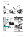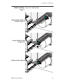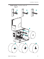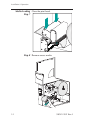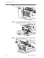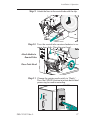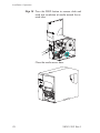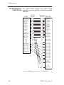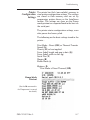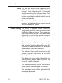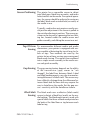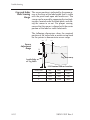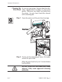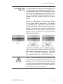
1
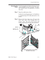
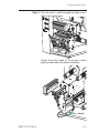
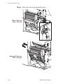
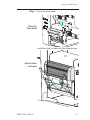
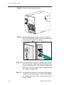
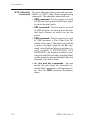
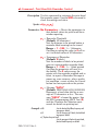
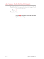
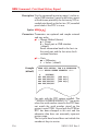
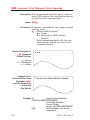
Thermal Printer
User’s Manual
2746e
User’s Manual No. 980412-001 Rev.A
©2002 ZIH Corp.
COPYRIGHT NOTICE
This document contains information proprietary to Zebra Technologies Corporation. This document and the information contained within is copyrighted by Zebra Technologies Corporation and
may not be duplicated in full or in part by any person without written approval from Zebra Technologies Corporation. While every effort has been made to keep the information contained within current and accurate as of the date of publication, no guarantee is given or implied that the document
is error-free or that it is accurate with regard to any specification. Zebra Technologies Corporation
reserves the right to make changes, for the purpose of product improvement, at any time.
TRADEMARKS
2746e is a service mark and Zebra is a trademark of Zebra Technologies Corporation. Windows
and MS-DOS are registered trademarks of Microsoft Corp. All other marks are trademarks or registered trademarks of their respective holders.
2746e Thermal Printer
European Council
Directive
89/336/EEC
Compliance to Standards
EMC Directive
EN55022-B, 1998
RF Emissions control
EMC Directive
EN55024, 1998
Immunity to Electromagnetic Disturbances
EMC Directive
EN61000-3-2: 1995
Harmonic Emissions
EMC Directive
EN61000-3-3: 1995
Voltage Variation
CB Scheme
EN60950 IEC60950
Product Safety
FCC - DECLARATION OF CONFORMITY:
Model: 2746e conforms to the following specification:
FCC Part 15, Subpart B, Section 15.107(a) and Section 15.109(a) Class B
digital device
Supplemental Information:
This device complies with Part 15 of the FCC Rules. Operation is subject to the following Two Conditions: (1) This device may not cause harmful interference , and (2) this device must accept any
interference received, including interference that may cause undesired operation.
INDUSTRY CANADA NOTICE:
This device complies with Industry Canada ICS-003 class B requirements.
Cet equipement est conforme a l’ICS-003 classe B de la norm Industrielle Canadian
ii
980412-001 Rev.A
Table of Contents
Installation & Operation. . . . . . . .
Unpacking Your Printer . . . . . . .
Getting To Know Your Printer . . . .
Controls & Indicators . . . . . . . .
Installation . . . . . . . . . . . . . .
Media Loading. . . . . . . . . . . .
Before You Load Media in the Printer
Using AutoSense. . . . . . . . . . .
Label Dispense Mode . . . . . . . .
Media Rewinding . . . . . . . . . .
Loading Transfer Ribbon . . . . . .
.
.
.
.
.
.
.
.
.
.
.
.
.
.
.
.
.
.
.
.
.
.
.
.
.
.
.
.
.
.
.
.
.
. . .
. . . .
. . . .
. . . .
. . . .
. . . .
. . . .
. . . .
. . . .
. . . .
. . . .
.
.
.
.
.
.
.
.
.
.
.
.
.
.
.
.
.
.
.
.
.
.
1-1
1-1
1-2
1-4
1-5
1-8
1-10
1-18
1-19
1-24
1-29
Troubleshooting . . . . . . . . . . . . . . . .
Where to Start . . . . . . . . . . . . . . . . .
Serial Interface Communication Configuration.
Serial Interface Cable Wiring. . . . . . . . . .
USB Interface Cable Wiring . . . . . . . . . .
Parallel Interface Cable Wiring . . . . . . . . .
Printer Configuration Settings . . . . . . . . .
Media . . . . . . . . . . . . . . . . . . . . .
Media Sensing . . . . . . . . . . . . . . . . .
Sensor Positioning . . . . . . . . . . . . . . .
Top Of Form Sensing . . . . . . . . . . . . .
Gap and Index Hole Sensing Range . . . . . .
.
.
.
.
.
.
.
.
.
.
.
.
.
.
.
.
.
.
.
.
.
.
.
.
. . .
. . . .
. . . .
. . . .
. . . .
. . . .
. . . .
. . . .
. . . .
. . . .
. . . .
. . . .
.
.
.
.
.
.
.
.
.
.
.
.
.
.
.
.
.
.
.
.
.
.
.
.
A-1
A-1
A-4
A-4
A-5
A-6
A-7
A-8
A-8
A-9
A-9
A-10
Operator Maintenance . . . . .
Cleaning Your Printer . . . .
Cleaning the Print Head . . .
Extending Print Head Life . .
Print Head Care . . . . . . .
.
.
.
.
.
.
.
.
.
.
. . .
. . . .
. . . .
. . . .
. . . .
.
.
.
.
.
.
.
.
.
.
B-1
B-1
B-2
B-3
B-4
.
.
.
.
.
.
.
.
.
.
.
.
.
.
.
.
.
.
.
.
. . .
. . . .
. . . .
. . . .
. . . .
. . . .
. . . .
. . . .
. . . .
. . . .
. . . .
. . .
. . . .
. . . .
. . . .
. . . .
.
.
.
.
.
Using the Media Cutter . . . . . . . . . . . . . . . . . . . C-1
Cutter Specifications . . . . . . . . . . . . . . . . . . . . . . C-2
Mounting the Cutter . . . . . . . . . . . . . . . . . . . . . . C-3
Print Odometer . . . . . . . . . . . . . . . . . . . . . . . D-1
ELP2 Odometer Commands. . . . . . . . . . . . . . . . . . D-2
980412-001 Rev.A
iii
General Cautions and Warnings
This page describes general safety and maintenance warnings and cautions for the printer and
are referenced throughout the manual.
Warning - Shock Hazard
The printer should never be operated in a location where it can
get wet. Personal injury could result.
Warning - Static Discharge
The discharge of electrostatic energy that accumulates on the
surface of the human body or other surfaces can damage or
destroy the print head or electronic components used in this
device. DO NOT TOUCH the print head or the electronic
components under the print head assembly.
Caution - Printer Setup & Handling
1)When installing or modifying the printer setup or
configuration, ALWAYS TURN POWER OFF Before:
A) Connecting any cables.
B) Performing any cleaning or maintenance operations.
C) Moving the printer.
2) Damage to the printer interface connector, accessories or
door may result from placing the printer on it’s front bezel or
backside during unpacking or handling.
Media Warning
Always use high quality approved labels and tags. If adhesive
backed labels are used that DO NOT lay flat on the backing
liner, the exposed edges may stick to the label guides and
rollers inside the printer, causing the label to peel off from the
liner and jam the printer.
Media Reload Hint
If you should run out of labels while printing, DO NOT turn the
power switch OFF (0) while reloading or data loss may occur.
The printer will automatically resume printing when a new label
or ribbon roll is loaded.
Print Quality Tip
Print density (darkness) is affected by the heat energy (density
setting) applied and by the print speed. Changing both Print
Speed and Density may be required to achieve the desired
results.
iv
980412-001 Rev.A
Installation & Operation
1
Installation & Operation
Unpacking Your Open the shipping carton and remove the
Printer printer and its accessories.
S
tio
rs t a
e en
e tm
d in c u
o r Do
C Pd
r l an
a e re
B abtwa
L of
n
20
©
01
Z
eb
s
ie
g
lo
06
no -0
ch 51
Te 55
ra 10
C
o
rp
o
tio
ra
n
980412-001 Rev.A
1
Installation & Operation
Getting To Know
Your Printer
Lower Front Cover
(Lift Up & Out to Open)
Media Access
Cover
(Lift to Open)
Label Taken Sensor
Ribbon Core
(Shipped mounted on
Ribbon Tube)
Print Head
Assembly
& Bracket
Label Mode Switch
Interface
Connectors
Power Switch
& Cord Module
Print Head
Release Lever
Liner Rewind
Tube and Clip
Auxiliary Media Access
Media Sensor
and Guide
2
(Opening for Fan Fold &
External Media)
980412-001 Rev.A
Installation & Operation
Getting To Know
Your Printer
Ribbon Take-Up
Tube
Ribbon Supply
Tube
Media Roll
Holder
Controls
Platen
Roller
Rewind
Bracket
Print Width
Adjustment Knob
Platen
(Media Drive)
Roller Bracket
Liner "Peeler"
Gate
Print Head
Peel/Tear
Bar
980412-001 Rev.A
3
Installation & Operation
Controls &
Indicators
0 = Off
ON
1 = On
Button
O
Power
Indicator
OFF
O
Power Switch
Function
Press Once - Halt batch printing.
PAUSE
Error
Indicator
Press Second Time - Resume batch
printing operation.
Press Once - Feed one label or “form”.
FEED
CANCEL
Press & Hold - Feed a single label, stop,
feed a single label, stop, and so on until
the FEED button is released.
Press Once - resets and terminates any
print operation in progress.
Indicator LEDs
Condition Report
POWER
ERROR
On Solid
OFF
Power On
Flashing
OFF
Pause
OFF
Flashing
Print head open
OFF
On Solid
1) Hardware Error
2) Command Error
3) Media or Ribbon Out
Label Mode Switch
PEEL
BATC
H
4
Mode
Description
Peel
Print one label and pause. Remove label.
Prints next label. Repeats until print operation is completed. Use label liner
rewinder to peel the liner from the label.
Batch
Standard operation - Prints one or more
labels until the batch form (label) print
operation is complete.
980412-001 Rev.A
Installation & Operation
Installation The following steps will guide you through the
installation of the printer.
Step 1
Attach Power
2746
Pat. No.
5.813,34
6,068,413
5
Part No
Serial . : 120X XX-XX
No
X
. : XXXX
Model:
TLP 2746
XX XX
Mfg. Dat
e: 02/01/01
Inp
Par
ut Po
t Num
berwe
: 2746
r: 11
-120
5V
XXX
AC
-001
Serial No.
Check
Voltage
: 12345678
Input Pow
For hom
50/60
VAC, 2-1
e use
Hz
PEEL
912
er: 115-230
e or offic
EPL
6.3A
Amps, 50/6
0
Hz
BATC
H
N2557
I.T.E.
8T34
PEEL
®
MADE
IN
with forei
gn and USA
domestic
parts
BATC
H
Batch
Mode
O
O
0 = Off
See Warnings - Page iv
980412-001 Rev.A
5
Installation & Operation
Step 2
Attach Interface
Cable
CH
Parallel
Interface
PEEL
Serial
Interface
BATC
H
PEEL
USB
Interface
6
BATC
H
980412-001 Rev.A
Installation & Operation
Step 2
Attach Interface
Cable
PEEL
Internal ZebraNet
PrintServer II
(optional)
BATC
H
For details regarding this
interface and its operation,
refer to the user guide
supplied with your
Ethernet print server.
Step 3
Apply Power
O
O
I = On
980412-001 Rev.A
7
Installation & Operation
Media Loading Open the media access door.
Step 1
Step 2 Open the print head.
8
980412-001 Rev.A
Installation & Operation
Media Loading Open the media guide.
Step 3
Slide Media Guide to
Outside Stop (1)
Rotate Media Guide
to Open (2)
Media Guide Opened
980412-001 Rev.A
9
Installation & Operation
Before You Load You must remove the outside length of media
Media in the (that is, one, full revolution of labels and any
Printer liner). When you remove this part of the media,
you remove the oils, dust, and adhesives that
contaminate it. Tape or adhesive holds the loose
end and the outside length of media becomes
contaminated when handled or stored.
Labels
Remove all labels
that are held by
adhesives or tape
Tag Stock
Detach both ends of
the bottom tag
You must avoid dragging adhesive or dirty
media between the print head and platen. Such
an occurrence damages the print head and is
not covered under your warranty. Using clean
media prevents damage and reduces wear on
the print head and platen.
10
980412-001 Rev.A
Installation & Operation
Media Loading Load the media roll.
Step 4
980412-001 Rev.A
11
Installation & Operation
Media Loading Thread the media through the media sensor
Step 5 and guide assembly and under the print head.
Outside Wound
(50 2"
mm
)
(10 4"
0m
m)
Inside Wound
(50 2"
mm
)
(10 4"
0m
m)
Fan Fold
(50m2"
m)
(1004"
mm
)
Media Path
(Side View)
Open
12
Open
980412-001 Rev.A
Installation & Operation
Media Loading Slide the media to the inside of the printer.
Step 6 Place the media guide against the media.
Slide Media Inside
Rotate Media
Guide Down
Media Guide in
Locked Position
Adjust Media Guide
to Media Width
Media Guide Set
980412-001 Rev.A
13
Installation & Operation
Media Loading Close the print head.
Step 7
(50 2"
mm
)
(10 4"
0m
m)
Step 8 Remove excess media.
14
980412-001 Rev.A
Installation & Operation
Media Loading Adjust the label pressure control knob to match
Step 9 the width of the media in use.
Set Media Width
Label Width
Pressure Control
Knob Settings
2"(50mm) or Less
2" (50mm)
Greater Than 2" (50mm)
4" (100mm)
Step 10 Close the media access door.
980412-001 Rev.A
15
Installation & Operation
Media Loading Press the Feed button once (with the power apStep 11 plied and the power switch “ON”).
FEED
Power ON
Labels Loaded
Press FEED
Step 12 Set label detection parameters for media:
• Use the AutoSense procedure (page 18) for
first time use of new media to set transmissive
(gap) sensor.
• Use the AutoSense procedure for detection
of label and gap lengths.
• Use programming to set continuous media
mode. See the Q command in the EPL2 programmer's manual for details.
Configure the print mode with the O (thermal
transfer) and OD (direct thermal) commands.
See the EPL2 programmer's manual for
important details on the Option (O) command.
The print mode will be set until changed by
programming.
DO NOT turn the power switch OFF (0) while
reloading media or data loss may result. The
printer will automatically resume printing when
a new label roll has been loaded.
16
980412-001 Rev.A
Installation & Operation
Media Loading This step is not normally required. Some of the
Step 13 exceptions are listed below. If the media has:
• An irregular or non-square shape,
• More than one label across,
• Less than full width black marks, or
• The media uses index hole or notches (typically for tag stock).
See Appendix A, page A-2, for details on media
sensing, media and sensor adjustment range.
Pinch & Hold (1)
Slide while
Holding the Fins,
then Release (2)
Adjustment
Fins
Adjust Sensor
Position
Sensor & Marker
980412-001 Rev.A
17
Installation & Operation
Using AutoSense A u t o S e n s e s e t s t h e s e n s it iv it y o f t h e
transmissive sensor, measures and stores the
form (label) and gap lengths. For more details
on media sensing see Appendix A, page A-2. To
activate the AutoSense feature:
Step 1 Load labels into the printer. Do not use the peel
mode. Printer power is ON.
Step 2 Press and hold the PAUSE and CANCEL buttons for one (1) second.
Step 3 Release the CANCEL button only. Wait three
(3) seconds. Release the PAUSE button.
Step 4 The printer will advance 3-4 labels while performing the adjustment. When the adjustment
is complete, a status summary label will be
printed and the printer will be placed in Diagnostic Dump mode.
Step 5 Press the FEED button to exit the Dump mode.
Power On
Media Loaded
Batch Mode
PAUSE & CANCEL
PAUSE
3 sec.
1 sec.
PEEL
BATCH
Sample: DUMP Mode
Printout
FEED
4 MO3257 3.18.01
Serial port : 96,N,8,1
Image buffer size:245K
Fmem:000,0K,019.9K avl
Gmem:000K,0241K avl
Emem:000K,0241K avl
I8,0,001 rY
S8 D12 R032,000 ZT UN
q0784 Q1227,034
Option:D
11 12 13
now in DUMP
18
980412-001 Rev.A
Installation & Operation
Label Dispense The printer can dispense a single peeled label
Mode and rewind the backing in the Dispense (Peel)
mode. Removing the presented label will
prompt the printer to print the next label.
Step 1 Open the media access door. Load media (labels). Load and set label parameters (via
AutoSense or programmed with the Q command) in the printer.
Step 2 Press the FEED button until approximately 16
inches (40 cm) of media has exited the printer.
Power ON
Labels Loaded
Press FEED
Step 3 Remove the exposed labels from the media
liner (backing).
Peel Exposed Labels
980412-001 Rev.A
19
Installation & Operation
Label Dispense Push the bottom of the lower front cover with a
Mode - Step 4 firm, steady pressure to open liner peeler gate.
The label dispenser’s peeler gate will unlatch
and swing open.
Step 5 Thread the backing in between the platen roller
bracket and the liner peeler gate. Do not wrap
the liner through the white roller mounted on
peeler gate.
20
980412-001 Rev.A
Installation & Operation
Label Dispense Attach the backing to the rewind tube with the
Mode - Step 6 clip.
Attach Liner to
Rewind Tube
Step 7 Turn the rewind tube counter-clockwise to
remove liner slack.
Close liner peeler gate. Close the print head, if
open.
Remove Liner Slack
Close Liner
Peeler Gate
Close the Print Head
980412-001 Rev.A
21
Installation & Operation
Label Dispense Change the printer mode switch to “Peel”.
Mode - Step 8
Press the CANCEL button to initiate Label Dispense Mode to peel labels.
CANCEL
Switch to Peel Mode
PEEL
Press CANCEL
BATCH
Remove Slack (FEED)
Step 9 With the media access door open, swing the label taken sensor gate up to be in the active sensing position, as shown below. A screw releases
and secures the sensor gate to the upper front
cover, locking it in place. Always lock the gate.
Set Label Taken
Sensor to Active
Position
22
980412-001 Rev.A
Installation & Operation
Label Dispense Close the media access door.
Mode - Step 10
Close Printer
Press FEED
The media access door must be closed for the
label taken sensor to detect labels for the label
dispensing (peel mode) to work.
Press the FEED button until the first label is presented (peeled).
Step 11 Remove the label. The printer is ready to dispense labels.
Label Presented,
Remove Label
(Media Path Shown)
OR
PER MOT
EP
Present Label (FEED)
ST
980412-001 Rev.A
23
Installation & Operation
Media Rewinding The rewinder allows the print and rewind of
partial label rolls.
Rewinder Capacity
The quantity of media re-rolled will vary due to
e n v i ro n m e n t a l c o n d it io n s a n d m e d ia
properties.
Step 1 Open the media access door. Load media.
Load and set media parameters (via AutoSense
or programming with the Q command) in the
printer.
Step 2 Remove the lower front cover. Lift up on the
lower front cover while holding down the
printer’s base. The cover will un-snap with
steady upward pressure and slide up and then
out the front.
Lift (1)
Pull Out (2)
Reverse the process to re-install
the lower front cover
24
980412-001 Rev.A
Installation & Operation
Step 3 Open the liner peeler gate and print head.
Step 4 Remove the rewind bracket and thumb screw.
Step 5 Place the rewind bracket into the peel/tear bar
assembly.
980412-001 Rev.A
25
Installation & Operation
Step 6 Attach the rewind bracket to the printer with the
thumb screw.
Step 7 Pull media out the front of the printer. Remove
exposed labels from liner, if any.
16 inches
(40cm)
Step 8 Thread the backing between the rewind bracket
and the liner peeler gate.
26
980412-001 Rev.A
Installation & Operation
Step 9 Attach the liner to the rewind tube with the clip.
Step 10 Turn the rewind tube counter-clockwise to remove liner slack. Close the print head.
Attach Media to
Rewind Tube
Close Print Head
Step 11 Change the printer mode switch to “Batch”.
Press the CANCEL button to initiate batch label
processing for media rewinding.
CANCEL
PEEL
BATCH
980412-001 Rev.A
27
Installation & Operation
Step 12 Press the FEED button to remove slack and
wind one revolution of media around the rewind tube.
Close the media access door.
28
980412-001 Rev.A
Installation & Operation
Loading Transfer Refer to the following instructions for installaRibbon tion of the ribbon.
Step 1 Insert an empty ribbon core on the ribbon
take-up tube.
Insert Ribbon Core
Ribbon
Core
Step 2 Insert a transfer ribbon roll on the ribbon supply
tube. The transfer ribbon unwinds clockwise.
Open the print head.
Insert Ribbon Roll
Open Print Head
980412-001 Rev.A
29
Installation & Operation
Loading Transfer Thread the transfer ribbon under the print head
Ribbon- Step 3 assembly and counter-clockwise around the
ribbon core and take-up tube.
Attach the ribbon to the core with adhesive
tape. Turn the ribbon take-up tube counter-clockwise a minimum of two (2) times to
lock the ribbon on the core.
Thread Ribbon
Attach Ribbon to
Ribbon Core
Tape
Turn Ribbon
Take-Up Tube
30
980412-001 Rev.A
Installation & Operation
Loading Transfer Close the print head. Close the printer.
Ribbon - Step 4
Step 5 Configure the printer for thermal transfer printing via the printer software driver or programming. This activates the ribbon out sensor.
Configure the print mode with the O (thermal
transfer) and OD (direct thermal) commands.
See the EPL2 programmer's manual for
important details on the Option (O) command.
The print mode will be set until changed by
programming.
980412-001 Rev.A
31
Installation & Operation
32
980412-001 Rev.A
Troubleshooting
Appendix A
Troubleshooting
This section addresses the most common issues
you may face with operation, maintenance and
configuration of the printer.
Where to Start Your first troubleshooting reference source is
the Common Problems Troubleshooting table
on the following page.
980412-001 Rev.A
A-1
Troubleshooting
Common Printing Problems
Troubleshooting Guide
Problem
Solution or Reason
STATUS indicator does
1. Check power connections from the printer to
not light GREEN when
the outlet.
power switch is turned
2. Check that media and ribbon are loaded.
to the ON (1) position.
1. Verify that the labels are the correct type.
With the STATUS
2. Check the roll and verify that the print surface
indicator light GREEN,
faces up for printing.
the printer appears to
3. Check that the transfer ribbon is correctly
be working, but
routed and has the ink side out for thermal
nothing is printed.
transfer printing, only.
Printing is faded or
poor quality.
1. Clean the print head with cleaning pen.
2. Adjust print speed/darkness in software or
with programming.
3. Check the roll and verify that the media print
surface is facing up.
4. Verify that the correct combination thermal
transfer ribbon and media are in use.
5. Verify that the media width is set correctly.
See the media width adjustment on page 15.
Printing stops and the
STATUS indicator
lights RED.
1. Possible problem sensing labels with transmissive
(gap) sensor. Perform AutoSense adjustment.
Align the transmissive (gap) sensor position, see
page 17.
2. Possible problem with label media.
a) Gap between the bottom of a label and the
top of the next label should be at least 1/16"
(1.6mm).
b) For tags, see Gap and Index Hole Sensing
Range, page A-10.
c) Use only approved labels and tags.
3. Possible label jam.
4. Check that the media is correctly routed.
5. Possible software/programming problem.
a) Check the printer memory configuration.
b) Refer to the EPL2 Programming manual
for the correct data syntax.
6. Transmissive sensor is dirty. Clean media path.
A-2
980412-001 Rev.A
Troubleshooting
Problem
Solution or Reason
1. Check for Out-of-Media condition or missing
labels in the middle of a roll.
2. Check for Out-of-Ribbon condition or damage or previous use of ribbon in middle of the
roll.
3. Check that the ribbon and label media are
correctly routed.
4. When direct thermal printing, verify that the
programmed mode (or printer driver) is set for
direct thermal printing. See the programmer’s
Status Indicator is RED
manual for details.
5. Transmissive (gap) sensor is dirty. Clean the
media path.
6. Verify that the print head carriage is closed
and latched.
7. Verify that the media sensor is correctly positioned to detect an inter label gap, index
holes (notches), or black mark (stripes). See
page 17 for sensor location and setting.
Printer cuts (melts)
through the transfer
ribbon. The ribbon is
advancing normally,
i.e. at the same rate as
the media.
1. Verify the density (heat) setting. If this is unknown reduce setting several levels the until
the transferred ink is clear and the ribbon is
not damaged.
2. Verify that the correct media is in use.
3. Verify that the ink (transfer material) side is
out on the transfer ribbon roll.
Label Dispense Mode:
Printing does not stop
between labels.
1. The Peel/Batch switch in the rear of the
printer is not set to peel.
2. The cover is open or the label taken sensor is
not in the down (active) position. See page
22 for sensor location and setting.
Label Dispense Mode:
Prints one label and
stops.
1. Programming - Verify the quantity has been
correctly set.
Cutter Option:
Cutting labels instead
of cutting between
labels.
1. Programming - Verify form length setting.
2. Check that peel switch is in the "batch" position (towards outside of printer).
980412-001 Rev.A
A-3
Troubleshooting
Serial Interface The printer’s serial port is configured with the
Communication Y command for the printer. See the EPL2 proConfiguration grammer's manual for details.
The printer’s serial port default configuration is:
9600 baud
8 bit data
1 stop bit
No parity
Serial Interface The figure below displays the cable wiring reCable Wiring quired to use the printer’s serial interface
Host
N/C
RxD
TxD
DTR
GND
DSR
RTS
CTS
RI
DB-9
Pin #
1
2
3
4
5
6
7
8
9
DB-9
Pin #
1
2
3
4
5
6
7
8
9
Printer
+5 Volts*
TxD
RxD
N/C
GND
RDY
N/C
RDY
N/C
Female DB-9 to Male DB-9
Host
N/C
RxD
TxD
DTR
GND
DSR
RTS
CTS
RI
DB-25
Pin #
8
3
2
20
7
6
4
5
22
DB-9
Pin #
1
2
3
4
5
6
7
8
9
Printer
+5 Volts*
TxD
RxD
N/C
GND
RDY
N/C
RDY
N/C
Female DB-25 to Male DB-9
*+5 volts at 150 mA for external device (e.g. KDU or scanner)
A-4
980412-001 Rev.A
Troubleshooting
USB Interface The figure below displays the cable wiring
Cable Wiring required to use the printer's USB interface.
USB
Connector
2
3
1
4
Pin
Signal
1
Vbus - N/C
2
D-
3
D+
4
Ground
Shell
Shield /
Drain Wire
For printer supported operating systems and
USB drivers, see the software and documentation CD or visit the Zebra printer web site at:
http://www.zebra.com
For information on the USB interface go to the
USB web site, at:
http://www.usb.org
980412-001 Rev.A
A-5
Troubleshooting
Parallel Interface The figure below displays the cable wiring
Cable Wiring required to use the printer's Centronics parallel
interface.
HOST
DB-25
Pin No.
STROBE~
DATA 0
DATA 1
DATA 2
DATA 3
DATA 4
DATA 5
DATA 6
DATA 7
ACK~
BUSY
PAPER ERR.
SELECT
AUTOFD~
ERROR~
N/A
N/A
N/A
SIG. GND
SIG. GND
SIG. GND
SIG. GND
SIG. GND
SIG. GND
SIG. GND
1
2
3
4
5
6
7
8
9
10
11
12
13
14
15
16
17
18
19
20
21
22
23
24
25
Centronics
Pin No. PRINTER
1
2
3
4
5
6
7
8
9
10
11
12
13
14
15
16
17
18
19
20
21
22
23
24
25
26
27
28
29
30
31
32
33
34
35
36
STROBE~
DATA 0
DATA 1
DATA 2
DATA 3
DATA 4
DATA 5
DATA 6
DATA 7
ACK~
BUSY
PAPER ERR.
SELECT
AUTOFD~
n/c
SIG. GND
CHAS GND
+5V
SIG. GND
SIG. GND
SIG. GND
SIG. GND
SIG. GND
SIG. GND
SIG. GND
SIG. GND
SIG. GND
SIG. GND
SIG. GND
SIG. GND
n/c
ERROR~
SIG. GND
n/c
n/c
SELECTIN~
+5 volts at 300 mA for external device (e.g. PrintServer)
A-6
980412-001 Rev.A
Troubleshooting
Printer The printer has flash (non-volatile) memory to
Configuration store printer configuration settings. The settings
Settings are stored in flash memory and are set by
programing, printer drivers or the AutoSense
routine. The settings are show on the Dump
mode printout or a reported back to the host via
the serial port.
The printer retains configuration settings, even
after power has been cycled.
The following are the basic settings stored in the
printer.:
Print Mode - Direct (OD) or Thermal Transfer
Speed (S)
Density (D) or heat applied
Form (label) length and gap in dots (Q)
Form (label) width in dots (q)
Serial Port (Y)
Margin (R)
Buffer Mode (r)
Options: D
Print Mode is Direct Thermal (OD)
Dump Mode
Printout
(See the U command in
the Programmer’s manual
for details)
980412-001 Rev.A
A-7
Troubleshooting
Media The two types of print media supported by the
2746e printer are direct thermal and thermal
transfer. Direct thermal media is chemically
treated to produce print without a ribbon. Thermal transfer printing uses heat to transfer wax,
resin or a combination of both from the transfer
ribbon to the media.
The printer is set by default to direct thermal
printing. Setting the printer to thermal transfer
activate a ribbon out sensor.
Media Sensing The printer is equipped with a transmissive
(gap) sensor, reflective (black mark) sensor, and
a reflective ribbon out sensor. These sensors are
adjustable and are located in the media sensor
assembly. The printer also includes a reflective
(label taken) sensor in the door and a head
open sensor located in the inside wall.
The transmissive (gap) sensor is set by
AutoSense function and adjusts the sensitivity
and detection levels for the media in use. The
transmissive sensor also detects the media out
condition and index hole or notches.
The reflective (black mark) sensor senses light
(media) and dark (black marks) on the media
backing (or liner).
The ribbon out sensor reflects light off the print
head assembly. When ribbon is present (and
unused), the light is stopped.
The label taken sensor receives light reflected
from a peeled label waiting to be removed.
The head open sensor reflects light off the side
of an open print head.
A-8
980412-001 Rev.A
Troubleshooting
Sensor Positioning The printer has a moveable sensor to detect
inter label gaps, black lines or marks, and index
holes/notches on the media. For optimal operation, the sensor should be adjusted to center on
the label, black mark or index hole (or notch) of
the media in use.
Typically, media does not require a media sensor position adjustment if the sensor is pulled to
the outside adjustment position. The sensor position can be moved by squeezing the two locking fins, located under the media sensor and
guide assembly, and sliding the sensor in or out.
Top Of Form To accommodate different media and media
Sensing dimensions, your printer is equipped with sen-
sors capable of detecting the top of form for labels or tags. Two methods are used by the
printer for top of form sensing: gap sensing and
black mark sensing. The sensors are combined
into a single sensor assembly in the media sensor and guide assembly.
Gap Sensing The gap sensing feature depends on the ability
of the transmissive (gap) sensor to “see
through” the label liner between labels. Label
and label backing opacity vary due to manufacturing differences in label stock. The sensor may
have difficulty distinguishing the difference between labels and the liner and may require the
user to AutoSense the media. Set the gap sensor’s sensitivity with the AutoSense feature.
Black Mark The black mark uses a reflective (black mark)
Sensing sensor to detect a black line (mark) on the media backing. The black mark sensor is used with
special labels that have a black mark printed on
the back of the label liner or tag between each
label or tag.
980412-001 Rev.A
A-9
Troubleshooting
Gap and Index The sensor position is indicated by the green arHole Sensing row at the front of the label guide that is visible
Range with the print head open and media out. The
sensor can be moved by squeezing the two locking tabs, located under the label guide, and sliding the sensor in or out. For proper sensing,
ensure that the sensor is aligned with the center
portion of the label or index hole/notch.
The following dimensions show the required
position of the index hole or notch on tag stock
for the printer to demonstrate sensor range.
C
min.
Sensor
Adjustment
Range
max.
B
A
Tag Tear-away
Inside Edge
of Tag Stock
.314 Nominal Sensor Location
A-10
Dimension
Min.
Max.
Nominal
A
.236"
None
.512"
B
.079"
.512"
.118"
C
.098"
1.520"
N/A
980412-001 Rev.A
Operator Maintenance
Appendix B
Operator Maintenance
Cleaning Your The printer’s media path allows for cleaning
Printer and clearing of media jams. The user can clean
the print head, platen roller and areas adjacent
to the media path surfaces.
Warning -Shock Hazard - See page iv.
Always turn the printer off before cleaning.
The media path surfaces (except the print head)
can be cleaned with a lint free, clean, damp
cloth very lightly moistened with medical grade
alcohol. Alcohol may be used to help remove
any adhesive or label material buildup.
Warning - Static Discharge - See page iv.
Never touch the print head. Always clean the
print head with a cleaning pen (to protect the
print head from static discharge and fibers).
If a label has become jammed in the printer,
remove the label and any adhesive residue,
immediately. Adhesive may spread through out
the printer’s media path if not completely
removed. Many adhesives are permanent and
have short “set” times.
980412-001 Rev.A
B-1
Operator Maintenance
Cleaning the As you use your printer, the print head may bePrint Head come contaminated resulting in poor print
quality. Whenever new labels are loaded into
the printer, the print head should be cleaned
with a cleaning pen.
Step 1 Open the printer and the print head carriage.
Step 2 Gently rub the cleaning pen across the amber
area of the print head.
Allow the print head to dry for 1 minute before
loading labels.
Do Not Clean the Print Head with sharp
objects! Only used approved cleaning
materials.
B-2
980412-001 Rev.A
Operator Maintenance
Extending Print The print head is the most critical component in
Head Life your printer, and possibly the most delicate. It is
a consumable item just like the brakes on your
car, which will eventually wear over time. However, with ongoing careful attention and maintenance, you can extend the life of the print
head!
Below are photographs of three print heads.
The first print head is brand new. The second
has printed over 1 million linear inches of thermal transfer labels and has been properly maintained. The third print head has printed far
fewer labels, but without proper care and maintenance, signs of abrasion and contamination
build-up are evident.
New
Over 1 Million
Inches
(Properly Maintained)
Less Than 1 Million
Inches
(Without Proper Care)
Contaminant buildup occurs gradually and results in poor print quality that may look like
faded print or failed print element(s). This build
up is very resistant to cleaning with the
pre-soaked swabs and is difficult to remove.
Note - The one million inches of print head
usage shown in the illustration above is used for
reference only. The actual print head life will
vary due to environmental conditions, printer
setup and the properties of the media used. See
Print Head Care for more details.
980412-001 Rev.A
B-3
Operator Maintenance
Print Head Care The main factors that contribute to reduced
head life are:
• Touching the print head! Static electricity
can discharge and damage the print head.
The body's oils and acids also damage the
print head.
• Cleaning - For optimum performance,
clean the print head regularly after every roll
of thermal transfer ribbon or after every roll of
direct thermal labels.
• Abrasion - Over time, the movement of media/ribbon across the print head will wear
through the protective ceramic coating, exposing and eventually damaging the print elements (dots).
• Use of proper media - Use only approved
Zebra media. Non-approved media may
contain chemicals that can destroy or dramatically reduce the print head's life. Approved thermal transfer ribbons have a
special anti-stick back coating that helps to
dissipate static and provide lubrication.
• Ribbon Width - Ensure that the thermal
transfer ribbon is as wide or wider than the label media to prevent exposing the elements
to the more abrasive label material.
• Temperature - Print head density (heat) setting. Set the density to the lowest possible setting that prints a good image.
• Print Speed - Fast print speeds have higher
friction levels on the print head's surface.
• Regular Print Head Conditioning - Use
our Save-a-Print head cleaning film to remove print head contamination buildup
quickly and easily. (Part No.105950-047)
B-4
980412-001 Rev.A
Using the Media Cutter
Appendix C
Using the Media Cutter
Printers with the cutter option have a detachable cutter with a motorized blade. The cutter is
a self cleaning tag and label liner cutter.
Printers with cutters can dispense a single form
(label) that is automatically cut from the media
roll.
Guidelines Use the cutter to cut through continuous paper
from rolls and the liner between labels. Never
cut the portion of media that has adhesive or
adhesive backing.
You can switch cutting on and off by using the
OC command. You can set form length and
gap distances by using the Q command. Refer
to the EPL2 programmer’s manual for complete
programming information.
Keep the cutter dry. Never use any solutions or
solvents to clean the blade. If there is a jam, follow the steps for Clearing the Cutter.
980412-001 Rev.A
C-1
Using the Media Cutter
Cutter The cutter option is a field install able option,
Specifications only. The printer covers must be opened to gain
access to the main PCB to install the cutter. This
installation should be performed by qualified
service personnel.
Warranty
90 Days
Mean Time To
Failure (MTBF)
5000,000 cut cycles
Cutting Method
Rotating, double edged blade
Media
Media Type
Paper, Thermal Paper, Paper Tags, Paper Label Liners
Max. Density
200 grams/meter2
(approximately 0.010 inches (.254 mm) thick)
Min. Width
1.0 inches (25.4 mm)
Max. Width
4.13 inches (105 mm)
Once installed the cutter is removable to allow
printing in non cutter configurations.
Clearing the The only tool required to clear a jam is a pair of
Cutter small tweezers. Never use your fingers or sharp
objects to clear jams.
If you cannot remove the jammed media, call
for service.
C-2
980412-001 Rev.A
Using the Media Cutter
Mounting the Use this procedure to attach and remove a preCutter viously installed cutter on the printer. The operator should reverse the procedure to remove
the cutter.
Step 1 Open the media access door.
Load and set media parameters (via AutoSense
or programming with the Q command) in the
printer.
Step 2 Remove the lower front cover. Lift up on the
lower front cover while holding down the
printer’s base. The cover will un-snap with
steady upward pressure and slide up and out.
Lift (1)
Pull Out (2)
Reverse the process to re-install
the lower front cover
980412-001 Rev.A
C-3
Using the Media Cutter
Step 3 With the media access door open, swing the label taken sensor gate down (deactivates the
sensor, as shown below). A screw releases and
secures the sensor gate to the upper front cover,
locking it in place. Always lock the gate.
Step 4 Open the label peeler gate. Optional - Open the
print head.
C-4
980412-001 Rev.A
Using the Media Cutter
Step 5 Pass the cutter’s cable through the large access
hole in the peeler gate.
Attach the cutter cable to the printer’s cutter
plug located under the platen assembly.
Attach
980412-001 Rev.A
C-5
Using the Media Cutter
Step 6 Place the cutter onto the peel/tear bar.
Place Cutter on
Peel / Tear Bar
Mounted Cutter on
Peel / Tear Bar
C-6
980412-001 Rev.A
Using the Media Cutter
Step 7 Close the print head.
Close the
Print Head
Lock the cutter in place with the thumbscrew.
Attach Cutter
to Printer
980412-001 Rev.A
C-7
Using the Media Cutter
Step 8 Close the media access door.
Step 9 Change the printer mode switch to “Batch”.
Press the CANCEL button to initiate batch label
processing for media rewinding.
CANCEL
PEEL
BATCH
Step 10 Load media as required. Configure the printer
for the selected media with the AutoSense routine or programming. Continuous media and
black line or mark media require programming
for proper configuration.
Step 11 Configure the printer for cutting with programming. See the programmer’s manual for details
on setting and canceling cutter printer command settings.
C-8
980412-001 Rev.A
Print Odometer
Appendix D
Print Odometer
The 2746e printer includes a print odometer to
assist with printer maintenance and scheduling.
The print head, as a consumable item, wears
out and may need periodic replacement to
maintain print quality. The printer also needs
regular cleaning and print head conditioning to
maximize the service life of the printer and it’s
print head, see Appendix B, Printer Maintenance for more details. The print odometer can
assist with printer maintenance and scheduling.
The printer has the ability to report serial number, distance printed by the print head and total
distance printed by the printer.
The Real Time Clock (RTC) option adds the
ability to record the date with the print odometer data.
The printer has the ability to report when the
properly maintained print head has reached the
end its usable life cycle. By default, this feature is
disabled and must be activated with EPL2 programming commands. The end of print head
life message can also be customized to add service contact information.
980412-001 Rev.A
D-1
Print Odometer
ELP2 Odometer The print odometer data is accessed and conCommands trolled via EPL2 Page Mode programming
commands. The odometer commands are:
• URH command - Prints or reports via serial
or USB interfaces a print head history report
for up to ten print heads.
• URL command - Prints or reports via serial
or USB interfaces the current print head or
total print distance of media run on the
printer.
• URR command - Prints or reports via serial
or USB interfaces a Print Head Life Reminder status report. The report may include
a custom message stored by the oL command, to be displayed when a reminder is issued (default is PRINTHEAD LIFE
EXCEEDED), the distance needed to activate print head life reminder (warning) label,
and the frequency of reminder labels after the
reminder is on and in effect.
• oL, oLn and oLy commands - Set and
control the print head life (exceeded) reminder label’s parameters and reporting status. See the URR command description,
above.
D-2
980412-001 Rev.A
oL Command - Print Head Life Reminder Control
Description Use this command to customize the print head
life reminder report. See the URR command to
check the settings and status.
Syntax oL[p1,p2,p3]
Parameters No Parameters = Resets the parameters to
their default values for print head life reminder reporting.
p1 = Reminder Threshold
(Default: 50 kilometers)
Sets the distance to be printed before a
reminder label warning can be issued.
Range = 1 - 255; 1 = 1 kilometer
Omitting or setting the value to 0 will reset it to default value of 50 kilometers.
p2 = Frequency of Reminder
(Default: 0 labels)
Sets the number of labels to be printed
prior to issuing another reminder label.
Range = 1 - 255; 1 = 1 label printed
Omitting the parameter will reset it to
the default. The 0 value causes the
printer with the reminder enabled and in
effect, to report a Reminder Message at
power-up, error recovery, after a media
out condition, a reset or after the Cancel
button has been pressed on the printer.
p3 = Message “DATA”
(Default: PRINTHEAD LIFE EXCEEDED)
Represents a fixed data field for a message of 39 characters or less. The message “DATA” is bound by quotes. See
the EPL2 programming ASCII Text (A)
and the Character Set Selection commands for details on printing text.
Example oL40
; Sets the threshold to 40km, frequency and
; message are default
oL,5
; Sets the frequency to 5 labels, threshold and
; message are default
oL,,”Replace the print head”
; Sets the message to Replace the print head,
; threshold and frequency are default
980412-001 Rev.A
D-3
oLn Command - Disable Print Head Life Reminder
Description Use this command to deactivate the print head
life reminder reporting.
Syntax oLn
Parameters None
Use the URR command to check the Print Head
Life Reminder settings.
D-4
980412-001 Rev.A
oLy Command - Enable Print Head Life Reminder
Description Use this command to activate the print head life
reminder reporting.
Syntax oLy
Parameters None
Use the URR command to check the Print Head
Life Reminder settings.
980412-001 Rev.A
D-5
URH Command - Print Head History Report
Description Use this command to print or report (via the serial or USB interface) a print head history report
of the distance printed by the last twenty (20) recorded print heads or the last ten (10) recorded
print heads if the RTC is in use.
Syntax URH[p1p2]
Parameters Parameters are optional and maybe entered
and any order.
p1 = Report Method (device)
p = Printer
s = Serial port or USB interface
(default)
Sends information back to the host via
the serial port and the last active bi-directional interface.
p2 = Units
m = Millimeters
i = Inches (default)
Example
(default)
HEAD LIFE HISTORY FOR S/N XXXXXXXXXX
***** SERIAL NUMBER MISMATCH *****
#
001
002
003
004
DISTANCE
XXX,XXX,XXX"
XXX,XXX,XXX"
XXX,XXX,XXX"
XXX,XXX,XXX"
[XXX days]
[XXX days]
[XXX days]
For units with the RTC option installed: The
**SERIAL NUMBER MISMATCH ** line prints
when the serial number stored in the RTC does
not match the serial number stored on the
printer’s main PCBA. One or both the PCBA or
RTC has been changed in this unit and the
odometer data does not accurately represent
printer usage.
The last print head record does not include the
number of days in service.
D-6
980412-001 Rev.A
URL Command - Read Print Odometers
Description Use this command to print or report (via the serial or USB interface) latest active print odometer data stored in printer memory. Report
printer usage for one or both of the following:
• The current distance printed by the presently
installed print head.
• The total distance printed by the printer.
Syntax URL[p1p2p3]
Parameters Parameters are optional and maybe entered
and any order.
p1 = Report Method (device)
p = Printer
s = Serial port or USB interface
(default)
Sends information back to the host via
the serial port and the last active bi-directional interface.
p2 = Units
m = Millimeters (mm)
i = Inches (”)
(default)
p3 = Read Meter
h = Head Life (distance)
for the presently installed print head
t = Total Print Distance
None = Default - Prints both Head Life
and Total Print Distance report data
strings. Do not use both the p3 parameters, h and t.
Example
(default)
980412-001 Rev.A
HEAD usage = XXX,XXX,XXX "
TOTAL usage = XXX,XXX,XXX "
[XXX days]
[XXX days]
D-7
URR Command - Print Odometer Status Reporting
Description Use this command to print or report (via the serial or USB interface) the status and settings for
the print head life reminder label.
Syntax URRp1
Parameters Parameters are optional and maybe entered
and any order.
p1 = Report Method (device)
p = Printer
s = Serial port or USB interface
(default)
Sends information back to the host via
the serial port and the last active bi-directional interface.
Printout Example for
oL Command
Default Settings
N,0,0,
N = Inactive
0 = 50 kilometers
0 = 50 labels
Example of an
Activated Print Head
Reminder (oLy)
and the Parameters
Customized
(See below)
Y,40,25,CALL ZEBRA SERVICE PROVIDER
Example oLy
; Activates Print Head Life Reminder
oL40,25,”CALL ZEBRA SERVICE PROVIDER”
; Sets Threshold: 40 kilometers,
; Frequency: 25 labels,
; Message: “CALL ZEBRA SERVICE PROVIDER”
URRp
; Prints Print Odometer Status label (see
; example above)
D-8
980412-001 Rev.A