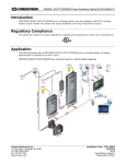
1
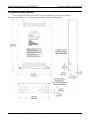
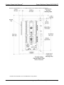
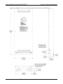
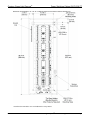
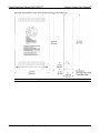
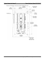
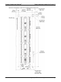
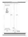
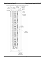
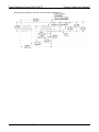
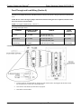
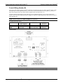
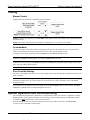
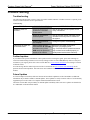
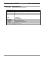
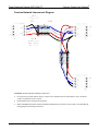
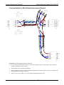
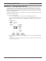
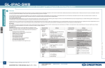
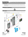
Green Light Express® Power Switching Cabinet GLPX-SW-FT
Introduction
Crestron Green Light Express® power switching cabinets are available with standard or hinged covers and come
pre-configured with GLXX switching modules already installed. The cabinets only require installation and wiring of
feed and load circuits.
Regulatory Compliance
The cabinet and modules are Listed to applicable UL Standards and requirements by Underwriters Laboratories Inc.
Application
The following diagram shows Crestron Green Light Express power switching cabinets in a lighting application that
is controlled by an IPAC system.
Crestron Green Light Express Power Switching Cabinets in a Typical Lighting Application
Crestron Electronics, Inc.
15 Volvo Drive Rockleigh, NJ 07647
Tel: 888.CRESTRON
Fax: 201.767.7576
www.crestron.com
Installation Guide – DOC. 6886B
(2025417)
05.12
Specifications subject to
change without notice.
Power Switching Cabinet GLPX-SW-FT
Crestron Green Light Express®
Physical Description
This section shows the dimensions of the Crestron Green Light Express power switching cabinets.
Dimensions of GLPX-SW-FT-8 , -16, -24 Power Switching Cabinets (Front, Side and Bottom View)
®
2 • Crestron Green Light Express Power Switching Cabinet GLPX-SW-FT
Installation Guide – DOC. 6886B
Crestron Green Light Express®
Power Switching Cabinet GLPX-SW-FT
Dimensions of GLPX-SW-FT-8 , -16, -24 (Shown Below) Power Switching Cabinets (Internal View)
* Installed GLXX modules come with additional tie wrap holders.
Installation Guide – DOC. 6886B
®
Crestron Green Light Express Power Switching Cabinet GLPX-SW-FT • 3
Power Switching Cabinet GLPX-SW-FT
Crestron Green Light Express®
Dimensions of GLPX-SW-FT-32, -40, -48, -56 Power Switching Cabinets (Front, Side and Bottom View)
®
4 • Crestron Green Light Express Power Switching Cabinet GLPX-SW-FT
Installation Guide – DOC. 6886B
Crestron Green Light Express®
Power Switching Cabinet GLPX-SW-FT
Dimensions of GLPX-SW-FT–32, -40, -48, -56 (Shown Below) Power Switching Cabinets (Internal View)
* Installed GLXX modules come with additional tie wrap holders.
Installation Guide – DOC. 6886B
®
Crestron Green Light Express Power Switching Cabinet GLPX-SW-FT • 5
Power Switching Cabinet GLPX-SW-FT
Crestron Green Light Express®
Dimensions of GLPX-SW-FT-24-HC Power Switching Cabinets (Front and Side View)
NOTE: Bottom view is shown on page 12.
®
6 • Crestron Green Light Express Power Switching Cabinet GLPX-SW-FT
Installation Guide – DOC. 6886B
Crestron Green Light Express®
Power Switching Cabinet GLPX-SW-FT
Dimensions of GLPX-SW-FT-24-HC Power Switching Cabinets (Internal View)
Installation Guide – DOC. 6886B
®
Crestron Green Light Express Power Switching Cabinet GLPX-SW-FT • 7
Power Switching Cabinet GLPX-SW-FT
Crestron Green Light Express®
Dimensions of GLPX-SW-FT-56-HC Power Switching Cabinets (Front and Side View)
NOTE: Bottom view is shown on page 12.
®
8 • Crestron Green Light Express Power Switching Cabinet GLPX-SW-FT
Installation Guide – DOC. 6886B
Crestron Green Light Express®
Power Switching Cabinet GLPX-SW-FT
Dimensions of GLPX-SW-FT-56-HC Power Switching Cabinets (Internal View)
Installation Guide – DOC. 6886B
®
Crestron Green Light Express Power Switching Cabinet GLPX-SW-FT • 9
Power Switching Cabinet GLPX-SW-FT
Crestron Green Light Express®
Dimensions of GLPX-SW-FT-84-HC Power Switching Cabinets (Front and Side View)
NOTE: Bottom view is shown on page 12.
®
10 • Crestron Green Light Express Power Switching Cabinet GLPX-SW-FT
Installation Guide – DOC. 6886B
Crestron Green Light Express®
Power Switching Cabinet GLPX-SW-FT
Dimensions of GLPX-SW-FT-84-HC Power Switching Cabinets (Internal View)
Installation Guide – DOC. 6886B
®
Crestron Green Light Express Power Switching Cabinet GLPX-SW-FT • 11
Power Switching Cabinet GLPX-SW-FT
Crestron Green Light Express®
Dimensions of GLPX-SW-FT-*-HC Power Switching Cabinets (Bottom View)
®
12 • Crestron Green Light Express Power Switching Cabinet GLPX-SW-FT
Installation Guide – DOC. 6886B
Crestron Green Light Express®
Power Switching Cabinet GLPX-SW-FT
Installation
Observe the following when installing the cabinet:
•
The cabinet must be mounted by a licensed electrician in accordance with all national and local codes.
Refer to the diagram below for specific requirements.
•
The cabinet is designed for surface mounting on a wall.
•
Cabinets are intended for indoor use only.
•
The ambient temperature range should be 32° F to 104° F (0° C to 40° C). The relative humidity should
range from 10% to 90% (non-condensing). Allow adequate clearance in front of the cover for servicing.
Mounting Location
Wall
3 ft
(0.9 m)
Minimum
Required
Clearance
Installation Guide – DOC. 6886B
®
Crestron Green Light Express Power Switching Cabinet GLPX-SW-FT • 13
Power Switching Cabinet GLPX-SW-FT
Crestron Green Light Express®
Wiring
NOTE: All wiring must be installed in accordance with all local and national electrical codes.
NOTE: Refer to the torque settings specified on pages 15 and 16.
Crestron Green Light Express cabinets are shipped with GLXX switching modules installed, refer to “Appendix A:
Specifications” on page 20 for the specifications of the modules. The following must be performed after mounting
the cabinet:
•
Connect incoming feed conductors to the L input terminals and connect loads to SW output terminals
(section A of the following diagram)
•
Connect control wiring (section B of the following diagram)
®
14 • Crestron Green Light Express Power Switching Cabinet GLPX-SW-FT
Installation Guide – DOC. 6886B
Crestron Green Light Express®
Power Switching Cabinet GLPX-SW-FT
Feed-Through and Load Wiring (Section A)
CAUTION: Bypass jumpers are provided on each output to allow testing and to protect the modules during
installation. The jumper shorts the L and SW terminals so that the load circuit is energized when the branch breaker
is on.
NOTE: Do not remove the bypass jumper until all feed and load wiring has been completed, and the circuits
have been tested for electrical faults.
NOTE: Use copper conductors only – rated 75° C.
Wire Gauge and Torque Values
TERMINAL
CONNECTOR MAX
WIRE RANGE
TORQUE
STRIP
LENGTH
L Inputs
26-10 AWG
5.31 lb-in (0.6 Nm) to
7.08 lb-in (0.8 Nm) max
3/8” (9 mm)
SW Outputs
26-10 AWG
5.31 lb-in (0.6 Nm) to
7.08 lb-in (0.8 Nm) max
3/8” (9 mm)
Ground Lug
14-4 AWG
25-45 lb-in (2.8-5.1 Nm)
3/4" (19 mm)
Load Wiring for GLXX-SW8 and GLXX-SW16
1.
Test the circuit for electrical faults by turning on each circuit breaker, checking that the breakers do not
trip, and that power is delivered to the proper loads.
2.
Turn off the circuit breaker(s) and remove all jumpers.
3.
Turn on the circuit breakers.
Installation Guide – DOC. 6886B
®
Crestron Green Light Express Power Switching Cabinet GLPX-SW-FT • 15
Crestron Green Light Express®
Power Switching Cabinet GLPX-SW-FT
Control Wiring (Section B)
The bottom of the cabinet contains Cresnet® connections for interfacing to the rest of the Crestron® control system.
It also provides override input which can be tied to devices such as the GLS-PLS-120/277 phase-loss sensor, or
other devices that provide a dry contact closure (manual switch, fire alarm relay, etc.).
To ensure optimum performance over the full range of your installation topology, use Crestron certified wire.
Failure to do so may incur additional charges if support is required to identify performance deficiencies because of
using improper wire.
NOTE: Interface connectors for NET and OVR ports are provided.
Wire Gauge and Torque Values
TERMINAL
CONNECTOR MAX
WIRE RANGE
TORQUE
STRIP
LENGTH
NET
26-12 AWG
4.43 lb-in (0.5 Nm)
1/4” (6 mm)
OVR
26-12 AWG
4.43 lb-in (0.5 Nm)
1/4” (6 mm)
Connector Wiring
NOTE: For instructions on network wiring, refer to “Appendix B: Network Wiring” on page 21.
®
16 • Crestron Green Light Express Power Switching Cabinet GLPX-SW-FT
Installation Guide – DOC. 6886B
Crestron Green Light Express®
Power Switching Cabinet GLPX-SW-FT
NET Port Wiring
When wiring the supplied NET connectors for connection to a Crestron control system or other device on the
Cresnet network, use Crestron certified wire such as CRESNET-NP or CRESNET-P. For instructions on
network wiring, refer to “Appendix B: Network Wiring” on page 21.
When daisy-chaining connections between NET ports, strip the ends of the wires carefully to avoid nicking the
conductors. Twist together the ends of the wires that share a pin on the network connector, insert the connection
into the Cresnet connector, tighten the retaining screw. Repeat the procedure for the other three conductors.
OVR (Override) Port Wiring
When a connection is applied between the OVR (override) terminals, the modules enter Override mode. The
Crestron GLS-PLS-120/277 phase-loss sensor or any device that provides a dry contact closure can be
connected to the supplied OVR connector on the bottom of the cabinet.
Installation Guide – DOC. 6886B
®
Crestron Green Light Express Power Switching Cabinet GLPX-SW-FT • 17
Power Switching Cabinet GLPX-SW-FT
Crestron Green Light Express®
Testing
Manual Control
Lighting loads can be manually controlled from the front panel.
NOTE: To disable local control, press the ENABLE button again or wait for two minutes. The red LED beside the
button deactivates.
NOTE: The control system program may change the settings if the Override mode is not enabled.
Override Mode
The Override mode overrides the control system program and sets all of the output states to the stored override
values. For instructions on saving override settings, refer to “Save Override Settings” below.
To enable Override mode, press and release the OVR button. The OVR LED flashes slowly.
NOTE: If the Override mode was enabled from an external device (i.e. a contact closure is present on the OVR
terminals), the OVR LED flashes quickly. Pressing the OVR button has no effect.
To disable Override mode, press the OVR button again. The OVR LED extinguishes and the outputs return to the
states set by the control system program.
NOTE: If override states have not been stored, the factory default override state is all loads on.
Save Override Settings
The state of each output can be saved as an override setting, which can be automatically recalled when the Override
mode is enabled.
NOTE: The control system program has a setting that can prevent locally saving the override state. If this setting is
enabled, the display shows “Er” when trying to save override states. For more information, refer to the SIMPL
Windows help file.
To save the state of an output as an override setting, press and hold the OVR button for three seconds. The OVR
LED blinks to indicate the new override setting has been stored.
System Operation and Commissioning
This cabinet has been designed as a component of a programmed Crestron system. Refer to “Appendix C: Setting
Module Net IDs” on page 24 for information on system setup. System commissioning by an authorized Crestron
representative must be performed to ensure system operation.
Once the cabinet has been wired and the modules have been tested, contact Crestron at 1-888-CRESTRON
[1-888-273-7876] to schedule commissioning.
®
18 • Crestron Green Light Express Power Switching Cabinet GLPX-SW-FT
Installation Guide – DOC. 6886B
Crestron Green Light Express®
Power Switching Cabinet GLPX-SW-FT
Problem Solving
Troubleshooting
The following table provides corrective action for possible trouble situations. If further assistance is required, please
contact a Crestron customer service representative.
Troubleshooting
TROUBLE
Module(s) does not
function.
Unit cannot be taken out
of Override mode
POSSIBLE CAUSE(S)
CORRECTIVE ACTION
Device is not receiving
power from a Crestron
power source.
Use the provided Crestron power source.
Verify connections.
Device is not receiving
sufficient power.
Use the Crestron Power Calculator to help
calculate how much power is needed for
the system.
System commissioning
not complete.
Arrange for system commissioning.
Short (contact closure)
exists between G and OVR
terminals on any of the
OVR terminals present at
bottom of the cabinet.
Determine the reason for the short.
Remove or remedy the short
(e.g. GLS-PLS-120/277 phase-loss sensor
may not have been installed properly, or
actual phase-loss has been detected).
Further Inquiries
If you cannot locate specific information or have questions after reviewing this guide, please take advantage of
Crestron's award winning customer service team by calling Crestron at 1-888-CRESTRON [1-888-273-7876]. For
assistance in your region, please refer to the Crestron Web site (www.crestron.com/offices) for a listing of Crestron
worldwide offices.
You can also log onto the online help section of the Crestron Web site (www.crestron.com/onlinehelp) to ask
questions about Crestron products. First-time users must establish a user account to fully benefit from all available
features.
Future Updates
As Crestron improves functions, adds new features and extends the capabilities of the GLPX-SW-FT, additional
information may be made available as manual updates. These updates are solely electronic and serve as intermediary
supplements prior to the release of a complete technical documentation revision.
Check the Crestron Web site periodically for manual update availability and its relevance. Updates are identified as
an “Addendum” in the Download column.
Installation Guide – DOC. 6886B
®
Crestron Green Light Express Power Switching Cabinet GLPX-SW-FT • 19
Crestron Green Light Express®
Power Switching Cabinet GLPX-SW-FT
Appendix A: Specifications
Specifications for the GLXX modules are listed in the following table.
GLXX Module Specifications
SPECIFICATION
DETAILS
Input Voltage
100 – 277 VAC 50/60 Hz
Supported Load Types
Incandescent, HID, magnetic low voltage (MLV), electronic low voltage
(ELV), neon/cold cathode, and fluorescent ballasts, motor
Maximum Load
Lighting
16 A per output
Motor
1 hp @ 120V
2 hp @ 230V/277V
Environmental
Temperature
32º to 104º F (0º to 40º C)
Humidity
10% to 90% RH (non-condensing)
Heat Dissipation
10 BTU/Hr
Cresnet Power Usage
5W (Entire Cabinet)
®
20 • Crestron Green Light Express Power Switching Cabinet GLPX-SW-FT
Installation Guide – DOC. 6886B
Crestron Green Light Express®
Power Switching Cabinet GLPX-SW-FT
Appendix B: Network Wiring
Check Network Wiring
Use the Right Wire
Calculate Power
In order to ensure optimum performance over the full range of your installation
topology, Crestron Certified Wire and only Crestron Certified Wire may be used.
Failure to do so may incur additional charges if support is required to identify
performance deficiencies because of using improper wire.
CAUTION: Use only Crestron power supplies for Crestron equipment. Failure to
do so could cause equipment damage or void the Crestron warranty.
CAUTION: Provide sufficient power to the system. Insufficient power can lead to
unpredictable results or damage to the equipment. Please use the Crestron Power
Calculator to help calculate how much power is needed for the system
(www.crestron.com/calculators).
When calculating the length of wire for a particular Cresnet run, the wire gauge and
the Cresnet power usage of each network unit to be connected must be taken into
consideration. Use Crestron Certified Wire only. If Cresnet units are to be daisychained on the run, the Cresnet power usage of each network unit to be daisychained must be added together to determine the Cresnet power usage of the entire
chain. If the unit is home-run from a Crestron system power supply network port, the
Cresnet power usage of that unit is the Cresnet power usage of the entire run. The
wire gauge and the Cresnet power usage of the run should be used in the following
equation to calculate the cable length value on the equation’s left side.
Cable Length Equation
40,000
L<
RxP
Where: L = Length of run (or chain) in feet
R = 6 Ohms (Crestron Certified Wire: 18 AWG (0.75 MM 2 ))
or 1.6 Ohms (Cresnet HP: 12 AWG (4 MM 2 ))
P = Cresnet power usage of entire run (or chain)
Make sure the cable length value is less than the value calculated on the right side of
the equation. For example, a Cresnet run using 18 AWG Crestron Certified Wire and
drawing 20 watts should not have a length of run more than 333 feet (101 meters). If
Cresnet HP is used for the same run, its length could extend to 1250 feet (381
meters).
NOTE: All Crestron certified Cresnet wiring must consist of two twisted pairs. One
twisted pair is the +24V conductor and the GND conductor and the other twisted
pair is the Y conductor and the Z conductor.
Strip and Tin Wire
When daisy-chaining Cresnet units, strip the ends of the wires carefully to avoid
nicking the conductors. Twist together the ends of the wires that share a pin on the
network connector and tin the twisted connection. Apply solder only to the ends of
the twisted wires. Avoid tinning too far up the wires or the end becomes brittle.
Insert the tinned connection into the Cresnet connector and tighten the retaining
screw. Repeat the procedure for the other three conductors.
Add Hubs
Use of a Cresnet Hub/Repeater (CNXHUB) is advised whenever the number of
Cresnet devices on a network exceeds 20 or when the combined total length of
Cresnet cable exceeds 3000 feet (914 meters).
Installation Guide – DOC. 6886B
®
Crestron Green Light Express Power Switching Cabinet GLPX-SW-FT • 21
Power Switching Cabinet GLPX-SW-FT
Crestron Green Light Express®
Crestron Network Interconnect Diagram
CAUTION: Possible Equipment Damage if Miswired
•
Do not power up system until all wiring is verified. Care should be taken to ensure Data (Y & Z), and Power
(24 & G) connections are not crossed.
•
Ground Shield at the Control System end only.
•
Model CNTBLOCK network terminal expander and diagnostic tool for the Cresnet system is recommended for
testing purposes and wiring convenience.
®
22 • Crestron Green Light Express Power Switching Cabinet GLPX-SW-FT
Installation Guide – DOC. 6886B
Crestron Green Light Express®
Power Switching Cabinet GLPX-SW-FT
Crestron Network to Mini Network Interconnect Diagram
CAUTION: Possible Equipment Damage if Miswired
•
Do not power up system until all wiring is verified. Care should be taken to ensure Data (Y & Z), and Power
(24 & G) connections are not crossed.
•
Ground Shield at the Control System end only.
•
Model CNTBLOCK network terminal expander and diagnostic tool for the Cresnet system is recommended for
testing purposes and wiring convenience.
•
Jumper wires: Use #18 AWG. Use a wire nut that accommodates all three wires.
Installation Guide – DOC. 6886B
®
Crestron Green Light Express Power Switching Cabinet GLPX-SW-FT • 23
Power Switching Cabinet GLPX-SW-FT
Crestron Green Light Express®
Appendix C: Setting Module Net IDs
The following procedure is normally performed by an authorized Crestron representative as part of the System
Commissioning phase. For system wiring and basic testing as described on pages 14 and 18, it is not necessary to
perform this step. Only perform this step if instructed by an authorized Crestron representative, or when replacing
modules on a system that have already been commissioned (in the latter case the Net ID should be set to match the
Net ID of the module being replaced).
The Net ID of each module in the cabinet can be changed from the front panel of each module. The Net IDs of each
module in the system must be unique.
To set the Net ID using the front panel:
1.
Press the recessed SETUP button to enter the Setup mode. The SETUP LED illuminates.
2.
As shown in the following diagram, press the left button under the NET ID display to change the left digit
of the Net ID or press the right button under the NET ID display to change the right digit of the Net ID
number.
Changing the Net ID
3.
When the desired Net ID is displayed, press the SETUP button to exit the Setup mode. The SETUP LED
extinguishes.
If the SETUP button is not pressed, the Setup mode times out after one minute of inactivity and the Net ID
reverts back to its original value.
®
24 • Crestron Green Light Express Power Switching Cabinet GLPX-SW-FT
Installation Guide – DOC. 6886B
Crestron Green Light Express®
Power Switching Cabinet GLPX-SW-FT
Return and Warranty Policies
Merchandise Returns / Repair Service
1.
No merchandise may be returned for credit, exchange or service without prior authorization from
Crestron. To obtain warranty service for Crestron products, contact an authorized Crestron dealer.
Only authorized Crestron dealers may contact the factory and request an RMA (Return
Merchandise Authorization) number. Enclose a note specifying the nature of the problem, name
and phone number of contact person, RMA number and return address.
2.
Products may be returned for credit, exchange or service with a Crestron Return Merchandise
Authorization (RMA) number. Authorized returns must be shipped freight prepaid to Crestron, 6
Volvo Drive, Rockleigh, N.J. or its authorized subsidiaries, with RMA number clearly marked on
the outside of all cartons. Shipments arriving freight collect or without an RMA number shall be
subject to refusal. Crestron reserves the right in its sole and absolute discretion to charge a 15%
restocking fee plus shipping costs on any products returned with an RMA.
3.
Return freight charges following repair of items under warranty shall be paid by Crestron,
shipping by standard ground carrier. In the event repairs are found to be non-warranty, return
freight costs shall be paid by the purchaser.
Crestron Limited Warranty
Crestron Electronics, Inc. warrants its products to be free from manufacturing defects in materials and
workmanship under normal use for a period of three (3) years from the date of purchase from Crestron, with the
following exceptions: disk drives and any other moving or rotating mechanical parts, pan/tilt heads and power
supplies are covered for a period of one (1) year; touch screen display and overlay components are covered for
90 days; batteries and incandescent lamps are not covered.
This warranty extends to products purchased directly from Crestron or an authorized Crestron dealer.
Purchasers should inquire of the dealer regarding the nature and extent of the dealer's warranty, if any.
Crestron shall not be liable to honor the terms of this warranty if the product has been used in any application
other than that for which it was intended or if it has been subjected to misuse, accidental damage, modification
or improper installation procedures. Furthermore, this warranty does not cover any product that has had the
serial number altered, defaced or removed.
This warranty shall be the sole and exclusive remedy to the original purchaser. In no event shall Crestron be
liable for incidental or consequential damages of any kind (property or economic damages inclusive) arising
from the sale or use of this equipment. Crestron is not liable for any claim made by a third party or made by the
purchaser for a third party.
Crestron shall, at its option, repair or replace any product found defective, without charge for parts or labor.
Repaired or replaced equipment and parts supplied under this warranty shall be covered only by the unexpired
portion of the warranty.
Except as expressly set forth in this warranty, Crestron makes no other warranties, expressed or implied, nor
authorizes any other party to offer any warranty, including any implied warranties of merchantability or fitness
for a particular purpose. Any implied warranties that may be imposed by law are limited to the terms of this
limited warranty. This warranty statement supersedes all previous warranties.
The specific patents that cover Crestron products are listed at patents.crestron.com.
Crestron, the Crestron logo, Cresnet, Fusion, Fusion EM and Green Light Express are either trademarks or registered trademarks of
Crestron Electronics, Inc. in the United States and/or other countries. UL and the UL logo are either trademarks or registered trademarks of
Underwriters Laboratories, Inc. in the United States and/or other countries. Other trademarks and trade names may be used in this document
to refer to either the entities claiming the marks and names or their products. Crestron disclaims any proprietary interest in the marks and
names of others.
©2012 Crestron Electronics, Inc.
Installation Guide – DOC. 6886B
®
Crestron Green Light Express Power Switching Cabinet GLPX-SW-FT • 25
Power Switching Cabinet GLPX-SW-FT
Crestron Green Light Express®
This page is intentionally left blank.
®
26 • Crestron Green Light Express Power Switching Cabinet GLPX-SW-FT
Installation Guide – DOC. 6886B