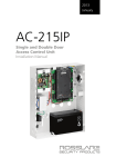
1
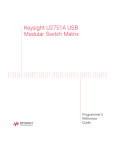
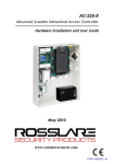
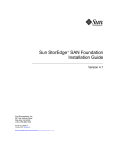
AYC-FGx4 Family Backlit, Waterproof Convertible Reader / Controllers Instruction Manual Models: AYC-F54 AYC-F64 AYC-G54 AYC-G64 August 2010 Table of Contents Table of Contents 1. General Information ........................................................ 4 1.1 1.2 1.3 1.4 2. Technical Specifications .................................................. 7 2.1 3. Key Features............................................................................... 8 Installation..................................................................... 10 3.1 4. 5. Introduction ................................................................................ 4 Reader/Controller Types ............................................................. 5 Box Content ............................................................................... 5 Ancillary Equipment ................................................................... 6 Mounting the AYC-Fx4 and AYC-Gx4 ....................................... 10 Wiring Instructions .......................................................... 11 Reader Functionality ...................................................... 14 5.1 5.2 Transmit Mode ......................................................................... 14 Programming the AYC-Fx4/AYC-Gx4 Series ............................. 14 Selecting Keypad Transmission Format ............................................................... 16 Selecting Proximity Card Transmission Format..................................................... 23 Changing the Programming Code .................................................................... 24 Changing the Facility Code................................................................................ 25 Return to Factory Default Settings ....................................................................... 26 Replacing a Lost Programming Code ................................................................ 26 6. Controller Functionality................................................... 27 6.1 Normal, Secure, and Master Users ........................................... 27 Normal User ........................................................................................................ 28 Secure User ......................................................................................................... 28 Master User.......................................................................................................... 28 6.2 Modes of Operation ................................................................ 28 Normal Mode ..................................................................................................... 28 Bypass Mode ...................................................................................................... 29 Secure Mode ...................................................................................................... 29 Changing the Modes of Operation .................................................................... 29 6.3 6.4 6.5 6.6 Auxiliary Input & Output ............................................................ 31 Door Alarms .............................................................................. 31 Internal Case and Back Tamper .............................................. 31 Lockout Feature (Keypad / Card Tamper) ............................... 31 AYC-Fx4 and AYC-Gx4 family manual Page ii Table of Contents 6.7 6.8 6.9 Request to Exit (REX) Function .................................................. 32 Secure Application Appurtenances ........................................ 32 Programming the AYC-Fx4/AYC-Gx4 ....................................... 33 Programming Menu ............................................................................................ 33 Entering Programming Mode.............................................................................. 34 Exiting Programming Mode................................................................................. 34 Changing Lock Strike Code ................................................................................ 34 Changing Auxiliary Code .................................................................................... 35 Changing the Programming Code .................................................................... 36 Changing the Normal / Secure Code ................................................................. 36 Changing the Normal / Bypass Code and Door Chime Settings ........................ 37 Setting Fail Safe/Secure Operation, Tamper Siren and Lock Strike Release Time 37 Defining the Auxiliary Input and Output ............................................................... 38 Quick Reference Guide for Auxiliary Mode Setting.............................................. 40 Detailed Reference Guide .................................................................................. 41 Setting the Lockout Feature ................................................................................ 45 Enrolling Primary and Secondary Codes ............................................................. 46 Deleting Primary and Secondary Codes ............................................................. 49 Relay Codes Assignment .................................................................................... 51 Relay Code Assignment using Search Method ................................................... 52 Pin Code Length / Factory Default Settings ......................................................... 53 Replacing a Lost Programming Code ................................................................ 54 Replacing a Lost Normal / Secure Code ............................................................ 54 Appendix A. Appendix B. Page iii Limited Warranty .......................................... 55 Technical Support ........................................ 57 AYC-Fx4 and AYC-Gx4 family manual General Information 1. General Information 1.1 Introduction The AYC-Fx4 and AYC-Gx4 series are a waterproof, standalone, convertible integrated reader and controller. The AYC-Fx4 and AYC-Gx4 series automatically determines whether to function as a reader or as a controller. If the unit is connected to a standard access control unit, then it functions as a reader. If the unit is connected to Rosslare's secure application appurtenances such as the PS-A25T, PS-C25T or PS-C25TU, it functions as a secured controller. For information on how the unit functions as a reader, see Reader Functionality on page 14. For information on how the unit functions as a controller, see Controller Functionality on page 27. All of the units are suitable for indoor or outdoor mounting. As a controller, the units accept up to 500 users, and allow entry via a personal identification number (PIN) and/or by presenting a proximity card. The pin code length for the controller has several options. The pin code length can be a set number of 4, 5 or 6 digits or it can be a 4-8 digits option. This manual contains the following information: • Installation • Wiring instructions • Operation Instructions AYC-Fx4 and AYC-Gx4 family manual Page 4 General Information 1.2 Reader/Controller Types The different types of units described in this manual are: • • • • AYC-F54 - PIN only AYC-F64 - PIN and Proximity card AYC-G54 – Mullion-Box PIN only AYC-G64 - Mullion-Box PIN and Proximity card Backlight AYC-F54 AYC-F64 AYC-G54 AYC-G64 Keypad Type 3X4 Standard 3X4 Standard 2X6 Mullion 2X6 Mullion Proximity Upon power-on reset, the AYC-Fx4 / AYC-Gx4 searches for the presence of Rosslare's secure application appurtenances. If a secure application appurtenances is detected, then the AYC-Fx4 / AYC-Gx4 are automatically configured as a secure access control unit. This is indicated by two short beeps. If the secured controller is not detected, it is automatically configured as a reader, indicated by one short beep. 1.3 Box Content Before beginning verify that all of the following is in the box. If anything is missing, please report the discrepancy to your nearest Rosslare office. • • • • One AYC-Fx4 / AYC-Gx4 unit Installation kit Installation and operating instructions secure application appurtenance (optional for controller applications) Page 5 AYC-Fx4 and AYC-Gx4 family manual General Information 1.4 Ancillary Equipment The following equipment is required to complete your installation: Reader • Compatible host controller (not supplied) - UL listed access control unit, i.e., model AC-215U Controller • Secure Application Appurtenances such as the PS-A25T, PS-C25T or PS-C25TU secure controllers This unit connects to the following: o Electric lock strike mechanism or a magnetic lock device, which implements fail safe (power to lock) or fail secure (power to open) functions. o Request to Exit (REX) button—normally open type. Switch is closed when pressed. o Door monitor switch. Rosslare accessories can be found on www.rosslaresecurity.com. AYC-Fx4 and AYC-Gx4 family manual Page 6 Technical Specifications 2. Technical Specifications Specifications AYC-F54 AYC-F64 AYC-G54 AYC-G64 Electrical Characteristics Power supply type Linear type – recommended Operating voltage range 5 - 16VDC (when used as a controller, provided by the secure application appurtenance) Input current standby 75mA (12VDC) 105mA 75mA 105mA Input current max (16VDC) 110mA 140mA 110mA 140mA LED control input Dry contact N.O. Tamper output Open collector, active low, 32mA max sink current Cable distance to host controller Up to 500ft (150 meters) using an 18AWG cable Max proximity card read range* N/A 3.0 inches (80mm) N/A 3.0 inches (80mm) Proximity card modulation N/A ASK at 125 KHz N/A ASK at 125 KHz Proximity card compatibility N/A EM cards N/A EM cards Card Transmit format (Reader) N/A 26-bit Wiegand, or Clock & Data N/A 26-bit Wiegand, or Clock & Data Keypad Transmit Format (Reader) Programmable PIN code formats LED indicators Two tri-colored LEDs Communication Data1/C1, Data0/C2—open collector, 5V termination Page 7 AYC-Fx4 and AYC-Gx4 family manual Technical Specifications Environmental Characteristics Operating temp. range -31to 151° F (-35 to 66° C) Operating humidity 0 – 95% (non-condensing) Outdoor usage Weather-resistant, meets IP-65, epoxy potted, suitable for outdoor use Mechanical Size (Height xWidth x Depth) 4.72x2.99x0.83 inches (120x76x21 mm) 5.39x1.73x0.83 inches (137x44x21 mm) Weight 0.474 lb (215g) 0.353 lb (160g) *Measured using Rosslare proximity card (AT-14) or equivalent. Range also depends on electrical environment and proximity to metal. 2.1 Key Features The key features for the AYC-Fx4 and AYC-Gx4 series are: • Built-In Proximity Card Reader (125 KHz ASK Modulation) (for 64 series only) • Red backlit keypad • Optical back tamper sensor and open controller tamper output. • Lockout feature on wrong entries (Keypad / Card Tamper) • Internal buzzer provides audible interface feedback • Two status / programming Interface LEDs (tri-colored) • Fully potted construction for outdoor use • Comes with mounting template for easier installation • Comes with an installation kit that includes a security screw and a security screw tool AYC-Fx4 and AYC-Gx4 family manual Page 8 Technical Specifications Reader • • • • Programmable keypad transmission format LED control input Programmable facility code Programmable Proximity Card Transmission Format o Clock & Data o 26-Bit Wiegand o Card + PIN Controller • Bi-directional secure communication with Rosslares’ secure application appurtenance • Three User Levels o Normal User o Secure User o Master User • "Code Search" feature that helps make maintaining user codes easier • Three Modes of Operation o Normal Mode o Bypass Mode o Secure Mode • Request-to-Exit (REX) signal from Rosslares’ secure application appurtenance • Chime Bell and Siren features are available with secure application appurtenance • Programmable Lock Strike Release, Siren, and Alarm Delay timers • Programmable Auxiliary input with versatile functions. • Programmable Auxiliary output functions • Programmable PIN code length. Page 9 AYC-Fx4 and AYC-Gx4 family manual Installation 3. 3.1 Installation Mounting the AYC-Fx4 and AYC-Gx4 Before starting, select the location to mount the AYC-Fx4 / AYCGx4. This location should be at shoulder height. Drill holes into the back of the unit according to how you want to mount the AYCFx4/AYC-Gx4. For US Gang Box installation, there are two-hole indicators on the back of the cover specifically aligned for the US Gang Box (A, in diagram below). AYC-Gx4 AYC-Fx4 Figure 1 Drilling mounting holes When the unit is used a reader, route the interface cable from the AYC-Fx4/AYC-Gx4 to the Controller. When the unit is used as a secured controller, route the interface cable from the AYC-Fx4 / AYC-Gx4 to Rosslares’ secure application appurtenance. A linear type power supply is recommended, when using the unit as a controller. Screw the AYC-Fx4/AYC-Gx4 back cover to its mounting location. Return the AYC-Fx4/AYC-Gx4 front cover to the mounted back plate. Secure the front cover by using the supplied security screw in the controllers Installation Kit. An L-Shaped tool is provided for use when tightening the security screw. AYC-Fx4 and AYC-Gx4 family manual Page 10 Wiring Instructions 4. Wiring Instructions The unit is supplied with a 22-inch pigtail, having a 6-conductor cable. To connect the unit to the controller, perform the following: Prepare the unit's cable by cutting the cable jacket back 1¼ inches and strip the wire ½ inch. Prepare the controller cable by cutting the cable jacket back 1¼ inches and strip the wire ½ inch. Splice the unit’s pigtail wires to the corresponding controller wires and cover each connection. Refer to the wire color table below, and to the wiring diagrams provided on the following pages. Reader Controller Color Functionality 5~16 VDC 5~16 VDC Red +DC Input Shield / Ground Shield / Ground Black Ground Data 1 / Clock C1 White Communication Data 0 / Data C2 Green Communication LEDCTL AUX. IN Brown LED Control / Auxiliary Input Tamper Tamper Purple Tamper If the tamper output is used, connect the purple wire to the correct input on the controller when used as a reader, or to a zone input of an intruder alarm system when used as a controller. Trim and cover all unused conductors. Note: • The individual wires from the unit are color-coded according the Wiegand standard. • When using a separate Power Supply for the Reader, this Power Supply and that of the Controller must have a common ground. • The Reader’s cable shield wire should preferably be attached to an earth ground, or a signal ground connection at the panel, or power supply end of the cable. This configuration is best for shielding the Reader cable from external interference Page 11 AYC-Fx4 and AYC-Gx4 family manual Wiring Instructions Wiring diagram #1 (below) shows the wiring for the Controller Application using a Dual Relay Secure Application Appurtenance. Rosslare PS-X25 Figure 2 Controller Application Wiring Diagram #1 Wiring diagram #2 (below) shows the auxiliary output connection using internal power. Rosslare PS-X25 Figure 3 Controller Application Wiring Diagram #2 AYC-Fx4 and AYC-Gx4 family manual Page 12 Wiring Instructions Wiring diagram #3 (below) shows the auxiliary output connection using the external power. Rosslare PS-X25 Figure 4 Controller Application Wiring Diagram #3 Figure 5: Reader Application Wiring Diagram #4 Page 13 AYC-Fx4 and AYC-Gx4 family manual Reader Functionality 5. Reader Functionality The AYC-Fx4/AYC-Gx4 series can function both as a reader and as a controller. If the unit is connected to standard access controller, it functions as a reader, indicated by one beep immediately after power-on reset. The following explains how the AYC-Fx4/AYC-Gx4 series functions as a reader. 5.1 Transmit Mode When the AYC-Fx4/AYC-Gx4 is in Transmit Mode, it is ready to receive data from a presented Proximity Card or an entered PIN code. When the reader is in Transmit Mode, the Transmit LED is red and the Program LED is off. Mode/Transmit Door/Program Red When a Proximity Card or Keyboard entry is being transmitted, the Transmit LED will flash green. Keyboard data can be sent via one of eight different Keypad Transmission Formats. For more information, see Selecting Keypad Transmission Format on page 16. Proximity Cards presented to the reader are always sent in either 26-Bit Wiegand, Clock & Data or, Wiegand Card + PIN format. See Selecting Proximity Card Transmission Format on page 23 for more information. 5.2 Programming the AYC-Fx4/AYC-Gx4 Series Programming the AYC-Fx4/AYC-Gx4 series is done solely via the unit's keypad driven Programming Menu System. To reach the AYC-Fx4 and AYC-Gx4 family manual Page 14 Reader Functionality Programming Menu System the AYC-Fx4/AYC-Gx4 must first be placed into Programming Mode. During the AYC-Fx4/AYC-Gx4 manufacturing process certain codes and settings are preprogrammed. These settings are the called the "Default Factory Settings". The table below shows the names of all the AYCFx4/AYC-Gx4 Menus. Programming Menu Default Factory Settings are marked by a "*" sign. Menu Description 1 Default Selecting Keypad Transmission Format Single Key, 6-Bit Wiegand (Rosslare Format) Single Key, 6-Bit Wiegand with Nibble + Parity Bits Single Key, 8-Bit Wiegand, Nibbles Complemented 4 Keys Binary + Facility Code, 26-Bit Wiegand 1 to 5 Keys + Facility Code, 26-Bit Wiegand 6 Keys BCD and Parity Bits, 26-Bit Wiegand Single Key, 3x4 Matrix Keypad 1 to 8 Keys BCD, Clock & Data 2 Selecting Card Transmission Format 26-Bit Wiegand Clock & Data Wiegand Card + PIN 3 * * Changing the Programming Code 1234 4 Changing the Facility Code 0 0 Return to Factory Default Settings Entering Programming Mode Mode/Transmit Door/Program 1) Press the # key 4 times. Red • Transmit LED will turn off. • Program LED will turn red. ? ? ? ? 2) Enter your 4 digit Programming Code. Door/Program Mode/Transmit If the Programming Code is Green valid, the door LED will turn Page 15 AYC-Fx4 and AYC-Gx4 family manual Reader Functionality green and the AYC-Fx4 / AYC-Gx4 will be in Programming Mode. Note: • The factory 4-digit Programming Code is 1234. • If a Programming Code is not entered within 30 seconds, the AYC-Fx4/AYC-Gx4 will return to Transmit Mode. Exiting Programming Mode 1) To exit the Programming Mode at any time press #: • You will hear a beep Mode/Transmit Door/Program • The Program LED will be off Red • The Transmit LED will turn red 2) This indicates that the AYC-Fx4/AYC-Gx4 has returned to Transmit Mode 3) Wrong entries may reset the reader back to Transmit Mode. While in Programming Mode if no key is pressed for 30 seconds the AYC-Fx4/AYC-Gx4 will exit Programming Mode and return to Transmit Mode. 5.2.1. Selecting Keypad Transmission Format The AYC-Fx4/AYC-Gx4 has eight different keypad transmission formats to select from. Follow the steps below to select the appropriate keypad transmission format that you wish to use. 1) Enter Programming Mode. Door/Program Mode/Transmit 2) Press “1” to enter. Green 1 Door/Program Mode/Transmit • The Transmit LED will turn Red Green Red. 3) Enter the appropriate option no. for the ? keypad transmission format that you wish to select (see table below). If an incorrect option no. is entered the reader will return to AYC-Fx4 and AYC-Gx4 family manual Page 16 Reader Functionality Transmit Mode and the keypad transmission format will remain unchanged 4) Look on the next page for more information on keypad transmission formats. 5) System returns to Transmit Mode. Door/Program • You will hear three beeps. Mode/Transmit • The Program LED will turn off Red • The Transmit LED will turn red Note: • Only one keypad transmission format can be active at any one time. • When using the keypad transmission format "1 to 8 keys BCD, Clock & Data" (Option 8) an additional input is required to specify the number of keys in the PIN code. Keypad Transmission Format Option Number See the table below to determine the Option Number for the Keypad Transmission Format you wish to select Keypad Transmission Format Option Number Single Key, 6-Bit Wiegand (Rosslare Format) 1* Single Key, 6-Bit Wiegand with Nibble + Parity Bits 2 Single Key, 8-Bit Wiegand, Nibbles Complemented 3 4 Keys Binary + Facility Code, 26-Bit Wiegand 4 1 to 5 Keys + Facility Code, 26-Bit Wiegand 5 6 Keys BCD and Parity Bits, 26-Bit Wiegand 6 Single Key, 3x4 Matrix Keypad 7 1 to 8 Keys BCD, Clock & Data Single Key 8 * Option 1 is the default factory setting. More information on each of the different keypad transmission formats is available below and on the following pages. Page 17 AYC-Fx4 and AYC-Gx4 family manual Reader Functionality Option 1: Single Key, 6-Bit Wiegand (Rosslare Format) Each key press immediately sends 4 bits with 2 parity bits added. Even parity for the first 3 bits and odd parity for the last 3 bits. 0= 1 1010 0 ="A" in Hexadecimal 6= 1 0110 0 1= 0 0001 0 7= 1 0111 1 2= 0 0010 0 8= 1 1000 1 3= 0 0011 1 9= 1 1001 0 4= 1 0100 1 *= 1 1011 1 ="B" in Hexadecimal 5= 1 0101 0 #= 0 1100 1 ="C" in Hexadecimal Option 2: Single Key, 6-Bit Wiegand Nibble and Parities Each key press immediately sends 4 bits with 2 parity bits added. Even parity for the first 3 bits and odd parity for the last 3 bits. 0 = 0 0000 1 6 = 1 0110 0 1 = 0 0001 0 7 = 1 0111 1 2 = 0 0010 0 8 = 1 1000 1 3 = 0 0011 1 9 = 1 1001 0 4 = 1 0100 1 * = 1 1010 0 = "A" in Hexadecimal 5 = 1 0101 0 # = 1 1011 1 = "B" in Hexadecimal Option 3: Single Key, 8-Bit Wiegand Nibbles Complemented Inverts the most significant bits in the message leaving the least 4 significant bits as Binary-Coded Decimal (BCD) representation of the key. The host system receives an 8-bit message. 0 = 11110000 6 = 10010110 1 = 11100001 7 = 10000111 2 = 11010010 8 = 01111000 3 = 11000011 9 = 01101001 4 = 10110100 * = 01011010 = "A" in Hexadecimal 5 = 10100101 # = 01001011 = "B" in Hexadecimal AYC-Fx4 and AYC-Gx4 family manual Page 18 Reader Functionality Option 4: 4 Keys Binary + Facility Code, 26-Bit Wiegand Buffers 4 keys and outputs keypad data with a three digit facility code like a standard 26-Bit card output. The facility code is set in Programming Menu number four and can be in the range 000 to 255. The factory default setting for the facility code is 000. (See Changing the Facility Code on page 25 for more information). The keypad PIN code is 4-digit long and can range between 0000 and 9999. On the fourth key press of the 4 digit PIN code, the data is sent across the Wiegand Data lines as binary data in the same format as a 26-Bit Card. If the "*" key or the "#" key are pressed during PIN code entry, the keypad will clear the PIN code entry buffer, generate a beep and is ready to receive a new 4 digit keypad PIN code. If the entry of the 4 digits keypad PIN code is disrupted and no number key is pressed within 5 seconds, the keypad will clear the PIN code entry buffer, generate a beep and is ready to receive a new 4 digits keypad PIN code. (EP) FFFF FFFF AAAA AAAA AAAA AAAA (OP) Where: EP = Even parity for first 12 bits. OP = Odd parity for last 12 bits. F = 8-Bit Facility Code. A = 16-Bit code generated from keyboard. Page 19 AYC-Fx4 and AYC-Gx4 family manual Reader Functionality Option 5: 1 to 5 Keys + Facility Code, 26-Bit Wiegand Buffers up to 5 keys and outputs keypad data with a facility code like a 26-Bit card output. The facility code is set in Programming Menu number four and can be in the range 000 to 255. The factory default setting for the facility code is 000. (See Changing the Facility Code on page 25 for more information.) The keypad PIN code can be one to five digits long and can range between 1 and 65,535. When entering a keypad PIN code that is less than 5 digits long, the "#" key must be pressed to signify the end of PIN code entry. For keypad PIN codes that are 5 digits long, on the fifth key press of the 5 digit PIN code, the data is sent across the Wiegand Data lines as binary data in the same format as a 26-Bit Card. If the "*" key is pressed during PIN code entry or a PIN code greater than 65,535 is entered, the keypad will clear the PIN code entry buffer, generate a beep and is ready to receive a new 5 digit keypad PIN code. If the entry of the 1 to 5 digit keypad PIN code is disrupted and no number key or "#" key is pressed within 5 seconds, the keypad will clear the PIN code entry buffer, generate a medium length beep and is ready to receive a new 1 to 5 digit keypad PIN code. (EP) FFFF FFFF AAAA AAAA AAAA AAAA (OP) Where: EP = Even parity for first 12 bits. OP = Odd parity for last 12 bits. F = 8-Bit Facility Code. A = 16-Bit code generated from keyboard. AYC-Fx4 and AYC-Gx4 family manual Page 20 Reader Functionality Option 6: 6 Keys BCD and parity bits, 26-Bit Wiegand Sends buffer of 6 keys, adds parity and sends a 26-Bit BinaryCoded Decimal (BCD) message. Each key is a four bit equivalent of the decimal number. The keypad PIN code must be 6 key presses long. On the sixth key press of the 6 digit PIN code, the data is sent across the Wiegand Data lines as a BCD message. If the entry of the 6 digit keypad PIN code is disrupted and no number key is pressed within 5 seconds, the keypad will clear the PIN code entry buffer, generate a medium length beep and is ready to receive a new 6 digit keypad PIN code. (EP) AAAA BBBB CCCC DDDD EEEE FFFF (OP) Where: EP = Even parity for first 12 bits. OP = Odd parity for last 12 bits. A = The first key entered. D = Fourth key entered B = Second key entered E = Fifth key entered. C = Third key entered F = Sixth key entered Option 7: Single Key, 3x4 Matrix Keypad (MD-P64) This unique mode is intended to let the host controller scan the AYC-Fx4/AYC-Gx4 keypad while still keeping the proximity card readers 26-Bit Wiegand or Clock & Data formats active. An optional interface board must be used between the AYCFx4/AYC-Gx4 and the host system. Each key press is immediately sent on DATA0 as an ASCII character at a baud rate of 9600 bits per second. When a key is pressed DATA1 is pulled "low" until the key is released at which point DATA1 will be set to "high". This allows the controller to detect the duration of the key press. Page 21 AYC-Fx4 and AYC-Gx4 family manual Reader Functionality The MD-P64 interface unit outputs the data received to 7 outputs emulating a keyboard. The interface unit will not affect any data that it receives from the proximity reader whether it is 26-Bit Wiegand or Clock & Data. Key pressed = ASCII Value 0 = '0' ( 0x30 hex ) 6 = '6' ( 0x36 hex ) 1 = '1' ( 0x31 hex ) 7 = '7' ( 0x37 hex ) 2 = '2' ( 0x32 hex ) 8 = '8' ( 0x38 hex ) 3 = '3' ( 0x33 hex ) 9 = '9' ( 0x39 hex ) 4 = '4' ( 0x34 hex ) *= '* ' ( 0x2A hex ) 5 = '5' ( 0x35 hex ) # = '#' ( 0x23 hex ) Option 8: 1 to 8 Keys BCD, Clock & Data Buffers up to 8 keys and outputs keypad data without a facility code like standard Clock and Data card output. The keypad PIN code can be one to eight digits long. The PIN code length is selected while programming the reader for Option 8. The reader will transmit the data when it receives the last key press of the PIN code. The data is sent across the two data output lines as binary data in Clock & Data format. If the "*" key or the "#" key are pressed during PIN code entry, the keypad will clear the PIN code entry buffer, generate a beep and is ready to receive a new keypad PIN code. If the entry of the digit keypad PIN code is disrupted and no number key or "#" key is pressed within 5 seconds, the keypad will clear the PIN code entry buffer, generate a medium length beep and is ready to receive a new keypad PIN code. Note: • When using the keypad transmission format "1 to 8 keys BCD, Clock & Data" (Option 8) an additional input is required to specify the number of keys in the PIN code. AYC-Fx4 and AYC-Gx4 family manual Page 22 Reader Functionality 5.2.2. Selecting Proximity Card Transmission Format The AYC-Fx4/AYC-Gx4 has three different proximity card formats to select from. Follow the steps below to select the appropriate Proximity Card reader transmission format that you wish to use. 1) Enter Programming Mode. Door/Program Mode/Transmit Green 2) Press “2” to enter Menu 2. 2 Door/Program Mode/Transmit • The Transmit LED will turn Red Green red. 3) Enter the appropriate option number for the proxy card transmission format that you wish to select (options below). If an incorrect option is entered the reader will return to Transmit Mode and the keypad transmission format will remain unchanged. 4) System returns to Transmit Mode • You will hear three beeps. Mode/Transmit Door/Program • The Program LED will turn off Red • The Transmit LED will turn red Proximity Card Transmission Format Option Number: Option 1: 26-Bit Wiegand Option 2: Clock & Data Option 3: Wiegand Card + PIN "Wiegand Card + PIN" Transmission Format This unique mode is intended to let host controllers get card and keypad data simultaneously. This option overrules the selected Keypad Transmission Format and sends the keypad data as described below. After a card is presented to AYC-Fx4/AYC-Gx4, the program LED starts to flash in Green and indicates that AYC-Fx4/AYC-Gx4 is waiting for the PIN code. If the entry of one to five digit keypad PIN code is disturbed and no digit key or # key is pressed within 5 Page 23 AYC-Fx4 and AYC-Gx4 family manual Reader Functionality seconds, the keypad will clear the card buffer and the PIN code entry buffer, generate a medium length beep and be ready to receive a new card. The keypad PIN code can be one to five digits long in the range of 0 to 99,999. When entering a keypad PIN code, the # key must be pressed to signify the end of the PIN entry. When pressing the # key press, the data is sent by the Wiegand data lines. If the * key is pressed, the keypad will clear the card buffer and the PIN code entry buffer, generate a medium length beep and is ready to receive a new card. AYC-Fx4/AYC-Gx4 output card data in 26-Bit Wiegand with the following keypad data in 26-Bit Wiegand format. Card Data: (EP) AAAA AAAA AAAA BBBB BBBB BBBB (OP) Where: EP =Even parity for first 12 A bits. OP =Odd parity for last B 12 bits. PIN Data: (EP) 0000 AAAA BBBB CCCC DDDD EEEE (OP) Where: A = The first key entered. B = Second key entered C = Third key entered EP =Even parity for first 12 bits. D = Fourth key entered E = Fifth key entered. OP =Odd parity for last 12 bits. If the PIN code is less than 5 digits, all the most significant nibbles are filled with 0. Example: (EP) 0000 0000 0000 0000 AAAA BBBB (OP) Where: A = The first key entered. EP =Even parity for first 12 bits. 5.2.3. B =Second key entered OP =Odd parity for last 12 bits. Changing the Programming Code 1) Enter Programming Mode. Door/Program Mode/Transmit Green 2) Press “3” to enter Menu 3. AYC-Fx4 and AYC-Gx4 family manual 3 Page 24 Reader Functionality Door/Program Mode/Transmit • The Transmit LED will turn Red Green red. 3) Enter the new 4 digit code you wish ? ? ? ? to set as the Programming Code 4) System returns to Transmit Mode • You will hear three beeps Door/Program Mode/Transmit • The Program LED will turn off Red • The Transmit LED will turn red Note: • Programming Code cannot be erased, i.e. the code 0000 is invalid and will not erase the Programming Code. • The factory default 4-digit Programming Code is 1234. 5.2.4. Changing the Facility Code Door/Program Mode/Transmit Green 1) Enter Programming Mode. 2) Press “4” to enter Menu 4. 4 • The Transmit LED will turn Door/Program Mode/Transmit red. Red Green 3) Enter the new 3-digit code you wish ? ? ? to set as the Facility Code 4) System returns to Transmit Mode • You will hear three beeps Door/Program Mode/Transmit • The Program LED will turn off Red • The Transmit LED will turn red Note: • Facility Code can be in the range of 000 to 255. • The default Facility Code is 0. Page 25 AYC-Fx4 and AYC-Gx4 family manual Reader Functionality 5.2.5. Return to Factory Default Settings Warning: 1) Enter You must be very careful before using this command! This will erase the entire memory and return all codes to their factory default setting. Programming Mode. Mode/Transmit Door/Program Green 2) Press “0” to enter Menu 0. 0 • The Transmit LED will Flash red. • The Program LED will flash Mode/Transmit red. Red Door/Program Red ? ? ? ? 3) Enter your 4 digit programming code • If the Programming Code is valid, all memory will be erased, you will hear three beeps and the controller will return to Normal Mode • If the Programming Code is invalid you will hear a long beep and the controller will return to Normal Mode without erasing the memory of the controller 5.2.6. Replacing a Lost Programming Code In the event that the Programming Code is forgotten, the AYCFx4/AYC-Gx4 may be reprogrammed in the field using the following instructions: 1) Remove power from the reader. 2) Activate tamper by removing the reader from the wall or removing the reader's case. 3) Apply power to the reader. 4) You now have 10 seconds to enter Programming Mode using the factory default Programming Code 1234. AYC-Fx4 and AYC-Gx4 family manual Page 26 Controller Functionality 6. Controller Functionality The AYC-Fx4/AYC-Gx4 series can function both as a reader and as a controller. If the unit is connected to Rosslares’ secure application appurtenance, it functions as a controller indicated by two beeps immediately after power-on reset. The lock strike output and Request to Exit input are not located on the AYC-Fx4/AYC-Gx4 unit, eliminating the possibility of unauthorized entry to the restricted area. The following explains how the AYC-Fx4/AYC-Gx4 series functions as a controller. 6.1 Normal, Secure, and Master Users The AYC-Fx4/AYC-Gx4 accepts up to 500 users and provides entry via the use of PIN codes and/or Proximity cards. Each user is provided with two code memory slots, Memory Slot 1 (Primary Code) and Memory Slot 2 (Secondary Code). The pin code length has several options. The pin code length can be a set number of 4, 5 or 6 digits or it can be a 4-8 digits option. When choosing the 4-8 digit option, please note that you should either enter zeros before the code, or press pound at the end (for example if your code is 12345, enter either 00012345 or 12345#). Note: Entering a code refers to either PIN or CARD depending on the model you have. The way in which the two memory slots are programmed determines a user’s access level and also determines the way in which the AYC-Fx4/AYC-Gx4 grants access in its three modes of operation. There are three user levels: Page 27 AYC-Fx4 and AYC-Gx4 family manual Controller Functionality 6.1.1. Normal User A Normal User only has a Primary Code and is only granted access when the AYC-Fx4/AYC-Gx4 is in Normal or Bypass Mode. 6.1.2. Secure User A Secure User must have a Primary and Secondary Code programmed; the two codes must not be the same. The Secure User can gain access when the AYC-Fx4/AYC-Gx4 is in any of its three modes of operation. In Normal Mode the Secure User must use their Primary Code to gain entry. In Secure Mode the Secure User must present both their Primary and Secondary Codes in order to gain entry. 6.1.3. Master User A Master User must have both Primary and Secondary Codes programmed with the same code. The Master User can gain access during any mode of operation by presenting their PIN code and/or Proximity card once to the controller. (The Master User is convenient but is less secure than a Secure User.) 6.2 Modes of Operation The AYC-Fx4/AYC-Gx4 has three modes of operation: 6.2.1. Normal Mode MODE LED is green Mode/Transmit Green Door/Program Normal Mode is the default mode. In Normal mode the door is locked until a Primary Code is presented to the controller. Special codes such as Lock Strike Code and Auxiliary Code are active in Normal mode. (See pages 34-35 for more information) AYC-Fx4 and AYC-Gx4 family manual Page 28 Controller Functionality 6.2.2. Bypass Mode Mode/Transmit Orange MODE LED is orange Door/Program In Bypass Mode, access to the premises is dependent on whether the controller's Lock Strike Relay is programmed for Fail Safe Operation or Fail Secure Operation. When the Lock Strike is programmed for Fail Secure Operation, the door is locked until the "*" button is pressed. When the Lock Strike is programmed for Fail Safe Operation, the door is constantly unlocked. 6.2.3. Secure Mode Door/Program Mode/Transmit MODE LED is red Red Only Secure and Master Users can access the premises during the Secured Mode. A Secure User must enter their Primary and Secondary Codes to gain entry. After entering their Primary Code the Door LED will flash green for 10 seconds, during which the Secondary Code must be entered. A Master User only needs to present their code once to gain entry. 6.2.4. Changing the Modes of Operation Changing from Normal Mode to Secure Mode The default factory setting for the Normal / Secure code is 3838. 1) Enter the Normal / Secure code • Mode LED will flash red 2) Press the “#” key to confirm the mode change. • Mode LED will turn red Page 29 Mode/Transmit Green Door/Program Mode/Transmit Door/Program Red Mode/Transmit Red Door/Program AYC-Fx4 and AYC-Gx4 family manual Controller Functionality Changing from Secure Mode to Normal Mode The default factory setting for the Normal / Secure code is 3838. 1) Enter the Normal / Secure code • Mode LED will flash green 2) Press the “#” key to confirm the mode change. • Mode LED will turn green Mode/Transmit Red Door/Program Mode/Transmit Door/Program Green Mode/Transmit Green Door/Program Changing from Normal Mode to Bypass Mode See Changing the Normal / Bypass Code and Door Chime Settings on page 37 to create/modify the Normal / Bypass code. 1) Enter the 4 digit Normal / Bypass code • Mode LED will flash Orange 2) Press the “#” key to confirm the mode change. • Mode LED will turn orange Mode/Transmit Door/Program Green Mode/Transmit Door/Program Orange Mode/Transmit Orange Door/Program Changing from Bypass Mode to Normal Mode See Changing the Normal / Bypass Code and Door Chime Settings on page 37 to create/modify the Normal / Bypass code. 1) Enter the 4 digit Normal / Bypass code • Mode LED will flash green 2) Press the “#” key to confirm the mode change. • Mode LED will turn green Mode/Transmit Orange Door/Program Mode/Transmit Door/Program Green Mode/Transmit Green AYC-Fx4 and AYC-Gx4 family manual Door/Program Page 30 Controller Functionality 6.3 Auxiliary Input & Output For optimum usability in different applications, the controller’s auxiliary input and output can be configured in ten different modes of operation. 6.4 Door Alarms Door alarms can be generated by connecting the Auxiliary Input to a Door Position Switch. Either Door-Forced or Door-Ajar conditions are supported, as well as, a configurable delay timer for each alarm type. Only one Door-alarm is enabled at any one time. Door alarms may activate auxiliary output and siren depending on the auxiliary settings. 6.5 Internal Case and Back Tamper In case the unit is forcibly opened or it is removed from the wall, a tamper event is triggered. A tamper output opens sending a signal to the connected Alarm system (purple wire) the event closes when the tamper is closed (case is re-closed or re-attached to the wall). The tamper event can also activate the auxiliary output if the controller is in Auxiliary Mode 3. Refer to the Quick Reference Guide for Auxiliary Mode Setting table, on page 40 below. 6.6 Lockout Feature (Keypad / Card Tamper) In case the controller is presented with wrong codes (PIN or Card), consecutively several times the unit goes into lockout mode. When a lockout occurs, the controller’s reader and keypad are de-activated so no codes can be entered until the set lockout period expires. During Lockout, Mode LED is Off, Door LED flashes Red, and the controller beeps every two seconds. Page 31 AYC-Fx4 and AYC-Gx4 family manual Controller Functionality 6.7 Request to Exit (REX) Function The REX Button is connected to Rosslares’ secure application appurtenance. The REX Button must be located inside the premises to be secured and is used to open the door without the use of a PIN code. It is usually located in a convenient location, e.g. inside the door or at a receptionist's desk. The function of the REX Button depends on whether the Lock Strike Relay is programmed for Fail Safe Operation or Fail Secure Operation. Fail Secure Operation: From the moment the REX Button is pressed, the door will be unlocked until the Lock Strike Release Time has passed. After this time, the door will be locked even if the REX Button has not been released. Fail Safe Operation: From the moment the REX Button is pressed, the door will be unlocked until the REX Button is released, plus the Lock Strike Release Time. In this case the Lock Strike Relay only begins its count down once the REX Button has been released. 6.8 Secure Application Appurtenances Rosslares’ secure application appurtenances are designed for use with Rosslare's secured series stand alone access control units, including AYC-FX4/AYC-GX4. It is designed to operate indoors and installed within the secured premises. The AYC-FX4/AYC-GX4 must be used with one of Rosslares’ secure application appurtenances, which provide Lock Strike output and Request to Exit (REX) Input. Both units communicate through a proprietary Rosslare protocol, which provides a secure link between the AYC-FX4/AYC-GX4 and the appurtenances. This in turn activates the door lock. The units also function as the power supply for the AYC-FX4/AYCGX4; they also contain a speaker connection for all sounder abilities. For more information see the specific Appurtenances Manual. AYC-Fx4 and AYC-Gx4 family manual Page 32 Controller Functionality 6.9 Programming the AYC-Fx4/AYC-Gx4 Programming the AYC-Fx4/AYC-Gx4 is done solely via the unit's keypad driven Programming Menu System. To reach the Programming Menu System the AYC-Fx4/AYC-Gx4 must first be placed into Programming mode. See Entering Programming Mode on page 34 for more information. During the AYC-Fx4/AYC-Gx4 manufacturing process certain codes and settings are pre-programmed. These settings are the called the Default Factory Settings. The table below shows the names of all the AYC-Fx4/AYC-Gx4 Menus. It also shows of all the AYC-Fx4/AYC-Gx4 default factory codes and settings. 6.9.1. Programming Menu Menu No. Menu Description 1 2 3 4 5 6 Changing Lock Strike Code Changing Auxiliary Code Changing Program Code Changing Normal/Secure Code Changing Normal/Bypass Code Changing Door Release Time Defining auxiliary inputs/outputs Set Lockout Enrolling PIN Code Deleting PIN Code Code assignment with strike/auxiliary Return to factory defaults / Change PIN code Length 7 8 9 0 Default 4 5 6 digit digit digit 2580 0852 1234 3838 N/A 0004 2004 4000 25802 08520 12341 38383 258025 085208 123412 383838 4-8 digits 25802580 08520852 12341234 38383838 You will find a complete description and instructions for each of the above menu items on the following pages. Page 33 AYC-Fx4 and AYC-Gx4 family manual Controller Functionality 6.9.2. Entering Programming Mode 1) Press the # key twice within 2 seconds. Mode/Transmit • Mode LED will turn off. • Door LED will turn red. 2) Enter your Programming Code • Door LED will turn green ? ? Mode/Transmit Door/Program Red ? ? Door/Program Green Note: • The AYC-Fx4/AYC-Gx4 must be in Normal Mode to enter the Programming mode. • The factory four digit Programming Code is 1234. • If a Programming Code is not entered within five seconds, the AYC-Fx4/AYC-Gx4 will return to Normal mode. 6.9.3. Exiting Programming Mode 1) Press the “#” key two times Door/Program Mode/Transmit within 2 seconds Green • You will hear 3 beeps. • The Door LED will turn off Door/Program Mode/Transmit and the Mode LED will Green return to Normal. 2) Wrong entries may reset the controller back to Normal mode. 3) While in Programming mode, if no key is pressed for one minute the AYC-Fx4/AYC-Gx4 will exit Programming mode and return to Normal mode. 6.9.4. Changing Lock Strike Code The Lock Strike Code is mainly used as a method to quickly test the Lock Strike Relay during installation. When the first user is added to the controller, the default Lock Strike Code will automatically be deleted. Once the code is programmed again, it will not be deleted with the entry of additional User Codes. 1) Enter Programming mode. Mode/Transmit AYC-Fx4 and AYC-Gx4 family manual Door/Program Green Page 34 Controller Functionality 1 2) Press “1” to enter Menu 1. • The Mode LED will turn Door/Program Mode/Transmit red. Red Green 3) Enter the new code you wish to set ? ? ? ? as the Lock Strike Code. Door/Program Mode/Transmit 4) System returns to Normal Green mode. • You will hear three beeps. Note: • • • • 6.9.5. Lock Strike Code does not work in the Secure Mode. Wrong entries will return the controller to Normal Mode. Code 0000 will erase the Lock Strike Code. The factory Default 4-digit Lock Strike code is 2580. Changing Auxiliary Code The Auxiliary Code is mainly used as a method to quickly test the Auxiliary Relay during installation. When the first user is added to the controller, the default Auxiliary Code will automatically be deleted. Once the code is programmed again, it will not be deleted with the entry of additional User Codes. 1) Enter Programming mode. Mode/Transmit Door/Program Green 2) Press “2” to enter Menu 2. 2 • The Mode LED will turn Door/Program Mode/Transmit orange. Orange Green 3) Enter the new code you wish to set as the auxiliary Code. ? ? ? ? 4) System returns to Normal Door/Program Mode/Transmit mode. Green • You will hear three beeps. Note: • • • • Page 35 Auxiliary code does not work in the Secure Mode. Wrong entries will return the controller to Normal Mode. Code 0000 will erase the Auxiliary Code. The factory Default 4-digit Auxiliary Code is 0852. AYC-Fx4 and AYC-Gx4 family manual Controller Functionality 6.9.6. Changing the Programming Code 1) Enter Programming mode. Door/Program Mode/Transmit Green 2) Press “3” to enter Menu 3. 3 • The Mode LED will turn green. 3) Enter the new code you wish to set ? ? ? as Programming Code 4) System returns to Normal Mode/Transmit mode. Green • You will hear three beeps. Mode/Transmit Green Door/Program Green ? Door/Program Note: • Programming Code cannot be erased, i.e. the code 0000 is not valid and will not erase the Programming Code. • The factory four digit programming code is 1234. 6.9.7. Changing the Normal / Secure Code 1) Enter Programming mode. 2) Press “4” to enter Menu 4 • The Mode LED will flash red. 3) Enter the new code you wish to set as Normal / Secure Code 4) System returns to Normal mode • You will hear three beeps Door/Program Mode/Transmit Green 4 Mode/Transmit Door/Program Red ? ? Mode/Transmit Green Green ? ? Door/Program Note: • Code 0000 will erase the Normal / Secure Code. • This code is disabled in case the Auxiliary Input is set to toggle between Normal and Secure access modes. • Default Normal/Secure code is 3838 AYC-Fx4 and AYC-Gx4 family manual Page 36 Controller Functionality 6.9.8. Changing the Normal / Bypass Code and Door Chime Settings 1) Enter Programming mode. Door/Program Mode/Transmit Green 2) Press “5” to enter Menu 5 5 • The Mode LED will flash Mode/Transmit Door/Program orange. Orange Green 3) Hereafter, are four different ways to program the normal / bypass code and door chime. a. Disable both Bypass Code and the door 0 0 0 0 chime. Enter the code 0000. b. Disable Bypass Code and enable the 0 0 0 1 door chime. Enter the code 0001. c. Enable Bypass Code and disable the ? ? ? 0 door chime. Enter any code ending with 0. d. Enable Bypass Code and enable the ? ? ? 0 door chime. Enter a code not ending with 0. 4) System returns to its normal mode. • You will hear three beeps. • The Door LED will turn off. Door/Program Mode/Transmit • The Mode LED will turn Green green. 6.9.9. Setting Fail Safe/Secure Operation, Tamper Siren and Lock Strike Release Time 1) Enter Programming mode. 2) Press “6” to enter Menu 6 • The Mode LED will flash green. Page 37 Door/Program Mode/Transmit Green 6 Mode/Transmit Door/Program Green Green AYC-Fx4 and AYC-Gx4 family manual Controller Functionality 3) Construct a code using instructions hereafter. First Digit ? ? ? ? For fail secure operation, the first digit is set to 0. For failsafe operation, the first digit is set to 1. Second Digit Siren Time in minutes (1-9, 0-disabled) Third and Fourth Digits Enter the number of seconds (from 1 to 99) that you want the Lock Strike to be released. For example, 0312 means Fail Secure Operation, a 3-minute Siren, and a 12-second Lock Strike release time. 4) System returns to its normal mode. • You will hear three beeps. Mode/Transmit • The Door LED will turn off. Green • The Mode LED will turn green. Door/Program Note: • Default value is 0004 which corresponds to Fail Secure operation, no siren, and 4-seconds Lock Strike release time. 6.9.10. Defining the Auxiliary Input and Output The default auxiliary setting is 2004. 1) Enter the Programming Mode. 2) Press 6 to enter Menu 6. • The Mode LED will flash green Door/Program Mode/Transmit Green 6 Mode/Transmit AYC-Fx4 and AYC-Gx4 family manual Door/Program Green Green Page 38 Controller Functionality 3) Construct a code using the instructions below. Auxiliary Mode 2 ? ? ? Auxiliary Setting Auxiliary Mode In addition to the Lock Strike Relay and Lock Strike REX, the AYC-FX4/AYC-GX4 features an Auxiliary Input. The Auxiliary Mode defines the function of the Auxiliary Input. Auxiliary Settings Each of the Auxiliary Modes has a two digit setting that affects how the Auxiliary Mode functions. 4) System returns to its normal mode. • You will hear three beeps. • The Door LED will turn off. Door/Program Mode/Transmit • The Mode LED will turn Green green. The Second digit defines Auxiliary Input function while the Third and Fourth digits may have no meaning or otherwise they define delay times for door monitor functions. Page 39 AYC-Fx4 and AYC-Gx4 family manual Controller Functionality 6.9.11. Quick Reference Guide for Auxiliary Mode Setting Auxiliary Auxiliary Input Mode Function Auxiliary Output Activated by Valid code or AUX REX Auxiliary Auxiliary Settings Relay (in seconds) 0 AUX REX 1 Normal/Secure switch Valid code N.O. 2 Normal/Secure switch Star button () N.O. 3 Normal/Secure switch Tamper event N.C. 4 5 6 7 8 Normal/Secure switch Direct shunt Door Monitor Shunt Door Monitor Forced door Door Monitor Door ajar LED control – Green Valid code N.O. N.C. N.C. N.C. N.O. 9 LED control - Red N.O. Valid code AYC-Fx4 and AYC-Gx4 family manual N.O. 01 to 99 Aux. relay release time 00 Aux. relay toggle 01 to 99 Aux. relay release time 00 Aux. relay toggle 01 to 99 Aux. relay release time 00 Aux. relay toggle 01 to 99 Aux. relay release time 00 Aux. relay tamper activated 01 to 99 Shunt time 01 to 99 Maximum shunt time 01 to 99 Forced delay 01 to 99 Ajar delay 01 to 99 Aux. relay release time 00 Aux. relay toggle 01 to 99 Aux. relay release time 00 Aux. relay toggle Page 40 Controller Functionality 6.9.12. Detailed Reference Guide The following are brief descriptions of each auxiliary mode. To implement the features of each mode, refer to Defining the Auxiliary Input and Output, page 38. Auxiliary Mode 0 Auxiliary input function: Activates the auxiliary output Auxiliary output activated by: Valid user code, Auxiliary code, Auxiliary input E.g. In auxiliary mode 0, the controller can function as a two-door controller. The auxiliary relay is to be attached to the lock on the second door. The auxiliary setting defines the door open time for the second door. The auxiliary input is to be attached to the REX pushbutton for the second door. Door Monitor input feature for the second door is not enabled when using this mode. Auxiliary Mode 1 Auxiliary input function: Toggles normal/secure modes Auxiliary output activated by: Valid user code, Auxiliary code E.g. In auxiliary mode 1, the controller can function as a two-door controller. The auxiliary relay is to be attached to the lock on the second door. REX feature for the second door is not enabled when using this mode. The auxiliary setting defines the door open time for the second door. The auxiliary input can switch the mode of operation of the controller between normal and secure mode. By connecting a switch timer or alarm system output to the auxiliary input, the controller can be automatically switched from normal mode (during office hours) to secure mode (after office hours). Page 41 AYC-Fx4 and AYC-Gx4 family manual Controller Functionality Auxiliary Mode 2 Auxiliary input function: Toggles normal/secure modes Auxiliary output activated by: Asterisk Button (*) E.g. In auxiliary mode 2, the auxiliary relay can function as a general purpose time switch that can be activated when the Asterisk button (*) is depressed. The auxiliary setting establishes for how long the auxiliary relay is to be activated. The auxiliary input can switch the mode of operation of the controller between normal and secure mode. By connecting a switch timer or alarm system output to the auxiliary input, the controller can be automatically switched from normal mode (during office hours) to secure mode (after office hours). Auxiliary Mode 3 Auxiliary input function: Toggles normal/secure modes Auxiliary output activated by: Alarms E.g. In auxiliary mode 3, the auxiliary output is activated if the controller is tampered; that is, if the case is forcibly opened or removed from the wall. The auxiliary input can switch the mode of operation of the controller between normal and secure mode. By connecting a switch timer or alarm system output to the auxiliary input, the controller can be automatically switched from normal mode (during office hours) to secure mode (after office hours). Auxiliary Mode 4 Auxiliary input function: Toggles normal/secure modes Auxiliary output activated by: direct shunt (explanation below) E.g. In auxiliary mode 4, the controller is capable of bypassing an alarm zone by shunting an alarm system’s door sensor. The auxiliary output is to be wired in parallel to the door sensor output. When in use, the auxiliary output is normally open and the door sensor functions normally. When a valid code is entered, the AYC-Fx4 and AYC-Gx4 family manual Page 42 Controller Functionality auxiliary relay shunts the door sensor for the duration of the shunt time, as defined by the auxiliary setting. If the door is left open longer than the shunt time, an alarm will be triggered. Auxiliary Mode 5 Auxiliary input function: Door Monitor Auxiliary output activated by: Shunt (explanation below) E.g. In auxiliary mode 5, the controller is capable of shunting an alarm system. In this mode, the auxiliary input is to be wired to the magnetic contact switch on the door. The auxiliary relay is wired to the alarm system. Without a valid code entered, the auxiliary relay will match the condition of the magnetic contact switch; if the door opens, the auxiliary relay will open; if the door closes, the auxiliary relay will close. When a valid code is entered, a count down for maximum shunt time, as defined by the auxiliary setting, begins; if the door is not closed before the maximum shunt time, the alarm will be triggered. Auxiliary Mode 6 Auxiliary input function: Door Monitor Auxiliary output activated by: Forced entry E.g. In auxiliary mode 6, the controller can trigger the auxiliary relay if the door has been forced. If the Siren Settings is enabled the siren will be activated. In this mode, the auxiliary input functions as a door monitor switch and is wired to the magnetic contact switch on the door. The auxiliary relay is to be wired to the alarm system. If the door is forced open, the controller will wait for the period of the forced door delay time to elapse and then, it will activate the auxiliary relay. The auxiliary setting sets the forced door delay period. Page 43 AYC-Fx4 and AYC-Gx4 family manual Controller Functionality Auxiliary Mode 7 Auxiliary input function: Door Monitor Auxiliary output activated by: Door Ajar (door held open) E.g. In auxiliary mode 7, the controller can trigger the auxiliary relay, if it detects that the door has been held open (ajar) too long. In this mode the auxiliary input functions as a door monitor switch and is wired to the magnetic contact switch on the door. The auxiliary relay is to be wired to the alarm system. If the door is opened, the controller will wait for the door ajar delay time to elapse and if the door does not close prior to the end of this period, the controller will activate the auxiliary relay. The auxiliary setting defines the door-ajar time. Auxiliary Mode 8 Auxiliary input function: Green LED control Auxiliary output activated by: Valid user code, Auxiliary code E.g. In auxiliary mode 8, the controller can function as a two-door controller and also provide indicator functionality control. The auxiliary relay is connected to the lock on the second door. The auxiliary setting defines the door open time for the second door. The auxiliary input is used to control the Door indicator. If the auxiliary input is open, the indicator will flash green; if the auxiliary input is closed, the Door indicator will flash red. Note: This mode takes control of the Door indicator LED. The indicator LED will not be lit when: A valid code is entered While in secure mode, when waiting for a secondary code. AYC-Fx4 and AYC-Gx4 family manual Page 44 Controller Functionality Auxiliary Mode 9 Auxiliary input function: Red LED control Auxiliary output activated by: Valid user code, Auxiliary code E.g. In auxiliary mode 9, the controller can function as a two-door controller and also provide indicator functionality control. The auxiliary relay is connected to the lock on the second door. The auxiliary setting defines the door open time for the second door. The auxiliary input is used to control the indicator. If the auxiliary input is open the Door indicator will flash red; if the auxiliary input is closed the Door indicator will flash green. Note: This mode takes control of the Door indicator LED. The indicator LED will not be lit when: A valid code is entered While in secure mode, when waiting for a secondary code. 6.9.13. Setting the Lockout Feature In case the controller is presented with wrong codes, consecutively several times the unit goes into lockout mode. When a lockout occurs, the controller keypad and reader are locked so no codes can be entered until the set lockout period expires. During Lockout, Mode LED is Off, Door LED flashes Red, and the controller beeps every two seconds. The default setting for the Lockout Feature is 4000 (Lockout Disabled) Note: Using the lockout feature is highly recommended, especially when selecting to use short PIN code length (4 or 5 digits). 1) Enter the Programming Mode. 2) Press 6 to enter Menu 6. • The Mode LED will flash green Page 45 Door/Program Mode/Transmit Green 6 Mode/Transmit Door/Program Green Green AYC-Fx4 and AYC-Gx4 family manual Controller Functionality 3) Construct a code using the following instructions: Set the number of wrong code attempts, which will cause Lockout between 0 and 9 attempts. 4 ? ? ? Sets the Duration of the lockout, between 00 and 99, the value is multiplied by ten, resulting in 0-990 seconds 6.9.14. Enrolling Primary and Secondary Codes Primary Codes • Primary Codes can only be enrolled to an empty User Slot, i.e. a slot where there is no existing Primary Code. • Primary Codes must be unique, i.e. one user’s Primary Code may not be the same as other users Primary Code. • Primary Codes cannot be the same as any system codes, such as the Normal / Secure Code or Lock Strike Code. • Users who hold a Primary Code can gain entry only during Normal mode. Secondary Codes • Secondary Codes can only be enrolled to User Slot that already has a Primary Code enrolled but no Secondary Code. • Secondary Codes do not have to be unique, i.e. multiple users can all hold the same Secondary Code. • Secondary Codes cannot be the same as any system codes, such as the Normal / Secure Code or Lock Strike Codes. • Users who hold Secondary Codes can gain entry in any Mode of Operation. AYC-Fx4 and AYC-Gx4 family manual Page 46 Controller Functionality Enrolling Primary and Secondary Codes There are two methods to enroll Primary and Secondary codes, the Standard Method and the Code Search Method. • The Standard Method is mainly used when the User Slot number for the user you wish to program is known. You can program both Primary and Secondary Codes using the Standard method. (See Enrolling Primary and Secondary Codes using the Standard Method on page 47.) • The Code Search Method is mainly used when enrolling a user’s Secondary Code and the User Slot Code is unknown. The Code Search method only works if a user’s Primary Code is already enrolled but the Secondary Code is not. (See Enrolling Secondary Codes using the Code Search Method on page 48.) Enrolling Primary and Secondary Codes using the Standard Method 1) Enter the Programming Mode. 2) Press 7 to enter Menu 7. Door/Program Mode/Transmit Green 7 • The Door LED will turn Door/Program Mode/Transmit orange Orange 3) Enter the 3-digit User Slot number ? ? ? between 001and 500 that you wish to enroll a Primary or Secondary code to. For example, User Slot 003 represents User #3. • If the selected slot has no Primary Code, the Mode LED will Mode/Transmit Door/Program flash green, indicating that the controller is ready Green Orange to accept a Primary Code. • If the selected slot already has a Primary Code but no Secondary Code, the Mode LED will flash red, indicating that the controller is ready Mode/Transmit Door/Program to accept a Secondary Red Orange Code. Page 47 AYC-Fx4 and AYC-Gx4 family manual Controller Functionality • If the selected slot already has a Primary and Secondary Door/Program Mode/Transmit Code, you will hear a Green long beep and the controller will return to Normal Mode. 4) Enter the PIN Code you wish to assign ? ? ? ? as the Primary or Secondary Code for this slot number. If the code entered is valid the Mode LED will stop flashing and then the controller is ready for you to enter the next 3-digit slot number (refer to step 2) that you want to assign a code to, or press the “#” key to move to the next slot number. If you do not wish to continue enrolling codes, press the “#” key twice and the controller will return to Normal mode. Enrolling Secondary Codes using the Code Search Method The Code Search feature enables you to quickly enroll a Secondary Code to a user who already has a Primary Code. 1) Enter the Programming Mode. 2) Press 7 to enter Menu 7. Door/Program Mode/Transmit Green 7 Mode/Transmit • The Door LED will turn orange 3) Enter 000 as the 3-digit User Slot 0 0 number. Door/Program Orange 0 Mode/Transmit Door/Program • The Door LED will flash Orange orange. The controller is now waiting for the Primary Code of the User to whom you want to add a Secondary Code. 4) Enter the Primary Code belonging to the user for whom you wish to add a Secondary Code. • The Mode LED will flash Mode/Transmit Door/Program red. Red Orange AYC-Fx4 and AYC-Gx4 family manual Page 48 Controller Functionality If the Primary Code entered is not valid, you will hear a long beep and the AYC-Fx4/AYC-Gx4 will continue to wait for a valid Primary Code. 5) Enter the Code to be used as the Secondary Code. If the Secondary Code is valid, the controller will beep three times and return to Normal Mode. If the Secondary Code is invalid the controller will sound a long beep, and the AYC-Fx4/AYC-Gx4 will continue to wait for a valid Secondary Code to be entered. 6.9.15. Deleting Primary and Secondary Codes There are two methods to delete Primary and Secondary codes: the Standard Method and the Code Search Method. When deleting a User Slot, both the Primary Code and the Secondary code are erased. Deleting Primary and Secondary Codes using the Standard Method 1) Enter the Programming Mode. 2) Press 8 to enter Menu 8. Door/Program Mode/Transmit Green 8 • The Door LED will turn Door/Program Mode/Transmit orange Red Orange • The Mode LED will turn red 3) Enter the 3-digit User Slot code you wish ? ? ? to delete. • The Mode LED will flash Mode/Transmit Door/Program red Indicating the Red Orange controller is waiting for the Programming Code to confirm the deletion. If the User Slot is empty, you will hear a long beep and the AYC-Fx4/AYC-Gx4 will return to Normal Mode. 4) Enter your programming code to ? ? ? ? confirm the deletion. Page 49 AYC-Fx4 and AYC-Gx4 family manual Controller Functionality If the programming code is valid, three beeps will be heard and the controller will return to its normal mode. If the programming code is invalid, a long beep will be heard and the controller will return to its normal mode. Note: It is recommended that a record be kept of added and deleted users so that it will be easier to keep track of which user slots are empty and which user slots are not. Deleting Primary and Secondary Codes using the Code Search Method 1) Enter the Programming Mode. 2) Press 8 to enter Menu 8. Door/Program Mode/Transmit Green 8 • The Door LED will turn Door/Program Mode/Transmit orange Red Orange • The Mode LED will turn red 3) Enter 000 as the 3-digit User Slot number. 0 0 0 • The Mode LED will turn Mode/Transmit Door/Program red. Red Orange • The Door LED will flash orange. The controller is now waiting for the Primary Code of the User you want to delete. 4) Enter the 4-8 digit PIN Code of the ? ? ? ? Primary Code belonging to the user you want to delete. Door/Program • The Mode LED will flash red Mode/Transmit Red Orange • The Door LED will flash orange 5) Enter your Programming Code to confirm the deletion. If the Programming Code is valid, you will hear three beeps and the unit will return to Normal Mode. AYC-Fx4 and AYC-Gx4 family manual Page 50 Controller Functionality If the Programming Code is invalid, you will hear a long beep and the unit will return to Normal Mode. Note: It is recommended that a record be kept of added and deleted users so that it will be easier to keep track of which user slots are empty and which user slots are not. 6.9.16. Relay Codes Assignment When a primary code is enrolled for any user, the user is authorized to activate the Lock Strike relay. However, different user codes may be set to operate the auxiliary relay instead or operate both the Lock strike and auxiliary relay. Assignment of such codes is achievable for any valid user code entered in the controller. There are two methods to assign relay codes to users: a standard method and a search method. Relay Code Assignment using Standard Method Mode/Transmit Door/Program 1) Enter the programming Green mode. 2) Depress 9 to enter Menu 9. 9 • The Mode LED will turn Mode/Transmit Door/Program green. Green Orange • The Door LED will turn orange. 3) Enter the 3-digit user slot for code ? ? ? assignment. • The Mode LED will flash Door/Program Mode/Transmit green. Green Orange 4) Enter the assignment digit for the current user slot: • 1 will activate the Lock Strike relay only deafult • 2 will activate the Auxiliary relay only • 3 will activate the Lock Strike and Auxiliary relays. Page 51 AYC-Fx4 and AYC-Gx4 family manual Controller Functionality If the assignment code is valid, Mode/Transmit Door/Program the Mode indicator will stop Green Orange flashing. The controller is now waiting for another slot number. Depress the # key to move to the next slot or enter a new slot number. If you do not wish to continue, depress the # key twice and the controller will return to its normal mode. 6.9.17. Relay Code Assignment using Search Method 1) Enter the programming Mode/Transmit mode. 2) Depress 9 to enter Menu 9. 9 • The Mode LED will turn green. Mode/Transmit • The Door LED will turn Green orange. 3) Enter 000 for user slot access. • The Door LED will flash orange. Mode/Transmit Door/Program Green Door/Program Orange 0 0 0 Door/Program Green Orange The controller is now waiting for the primary code of the user. 4) Enter the primary code Mode/Transmit Door/Program belonging to the user. Green Orange • The Mode LED will flash green. 5) Enter the assignment digit for the current user slot: • 1 will activate the Lock Strike relay only deafult • 2 will activate the Auxiliary relay only • 3 will activate the Lock Strike and Auxiliary relays. If the assignment digit is valid, three beeps will be heard and the controller will return to its normal mode. If the assignment digit is invalid, a long beep will sound and the controller will wait for another assignment digit to be entered. AYC-Fx4 and AYC-Gx4 family manual Page 52 Controller Functionality 6.9.18. Pin Code Length / Factory Default Settings Warning: • You must be very careful before using this command! Changing the pin code length will also erase the entire memory contents, including all user and special codes, and return all codes to their factory-default settings Door/Program 1) Enter the Programming Mode/Transmit Mode. Green 2) Select the desired pin code length as follows: a. 00 – Returns to factory defaults and sets a 4 digit code. b. 05 - Returns to factory defaults and sets a 5 digit code. c. 06 - Returns to factory defaults and sets a 6 digit code. d. 08 - Returns to factory defaults and sets a 4-8 digit code. Note: When choosing the 4-8 option, please note that you should either enter zeros before the code, or press pound at the end (for example if your code is 12345, enter either 00012345 or 12345#). • Both the Mode and Door Mode/Transmit Door/Program LEDs will flash red. Red Red 3) Enter your 4-8 digits Programming ? ? ? ? Code. • If the Programming Code is valid, all memory will be erased. You will hear three beeps and the controller will return to Normal Mode. • If the Programming Code is invalid you will hear a long beep and the controller will return to Normal Mode without erasing the memory contents. Page 53 AYC-Fx4 and AYC-Gx4 family manual Controller Functionality 6.9.19. Replacing a Lost Programming Code Note: 1) 2) 3) 4) 5) • The AYC-Fx4/AYC-Gx4 must be in Normal mode, otherwise this will not work. Make sure that the Mode LED is green before proceeding. Remove power from the Power Supply Unit. Press the REX Button on the Power Supply Unit. Apply power to the unit with REX button pressed. Release the REX Button. You now have 15 seconds to program a new Programming code into the Access Control unit using the default code based on the PIN code length you chose (see Programming Menu on page 33), before the controller reverts to the existing code. 6.9.20. Replacing a Lost Normal / Secure Code Note: 1) 2) 3) 4) 5) • The AYC-Fx4/AYC-Gx4 must be in Secure Mode, otherwise this will not work. Make sure that the Mode LED is red before proceeding. Remove power from the Power Supply Unit. Press the REX Button on the Power Supply Unit. Apply power to the unit with the REX button pressed. Release the REX Button. You now have 15 seconds to program a new Normal / Secure code into the Access Control unit using the default code based on the PIN code length you chose (see Programming Menu on page 33), before the controller reverts to the existing code. AYC-Fx4 and AYC-Gx4 family manual Page 54 Limited Warranty Appendix A. Limited Warranty ROSSLARE ENTERPRISES LIMITED S (Rosslare) FIVE YEARS LIMITED WARRANTY is applicable worldwide. This warranty supersedes any other warranty. Rosslare's FIVE YEARS LIMITED WARRANTY is subject to the following conditions: Warranty Warranty of Rosslare's products extends to the original purchaser (Customer) of the Rosslare product and is not transferable. Products Covered By This Warranty and Duration ROSSLARE ENTERPRISES LTD. AND / ORSUBSIDIARIES (ROSSLARE) warrants that the AYC-Fx4 and AYC-Gx4, convertible reader / secured controller family as listed above, to be free from defects in materials and assembly in the course of normal use and service. The warranty period commences with the date of shipment to the original purchaser and extends for a period of 5 years (60 Months). Warranty Remedy Coverage In the event of a breach of warranty, ROSSLARE will credit Customer with the price of the Product paid by Customer, provided that the warranty claim is delivered to ROSSLARE by the Customer during the warranty period in accordance with the terms of this warranty. Unless otherwise requested by ROSSLARE ENTERPRISES LTD. AND / OR SUBSIDIARIES representative, return of the failed product(s) is not immediately required. If ROSSLARE has not contacted the Customer within a sixty (60) day holding period following the delivery of the warranty claim, Customer will not be required to return the failed product(s). All returned Product(s), as may be requested at ROSSLARE ENTERPRISES LTD. AND /OR SUBSIDIARY’S sole discretion, shall become the property of ROSSLARE ENTERPRISES LTD. AND /OR SUBSIDIARIES. To exercise the warranty, the user must contact Rosslare Enterprises Ltd. to obtain an RMA number after which, the product must be returned to the Manufacturer freight prepaid and insured In the event ROSSLARE chooses to perform a product evaluation within the sixty (60) day holding period and no defect is found, a minimum US$ 50.00 or equivalent charge will be applied to each Product for labor required in the evaluation. Rosslare will repair or replace, at its discretion, any product that under normal conditions of use and service proves to be defective in material or workmanship. No charge will be applied for labor or parts with respect to defects covered by this warranty, provided that the work is done by Rosslare or a Rosslare authorized service center. Page 55 AYC-Fx4 and AYC-Gx4 family manual Limited Warranty Exclusions and Limitations ROSSLARE shall not be responsible or liable for any damage or loss resulting from the operation or performance of any Product or any systems in which a Product is incorporated. This warranty shall not extend to any ancillary equipment not furnished by ROSSLARE, which is attached to or used in conjunction with a Product, nor to any Product that is used with any ancillary equipment, which is not furnished by ROSSLARE. This warranty does not cover expenses incurred in the transportation, freight cost to the repair center, removal or reinstallation of the product, whether or not proven defective. Specifically excluded from this warranty are any failures resulting from Customer's improper testing, operation, installation, or damage resulting from use of the Product in other than its normal and customary manner, or any maintenance, modification, alteration, or adjustment or any type of abuse, neglect, accident, misuse, improper operation, normal wear, defects or damage due to lightning or other electrical discharge. This warranty does not cover repair or replacement where normal use has exhausted the life of a part or instrument, or any modification or abuse of, or tampering with, the Product if Product disassembled or repaired in such a manner as to adversely affect performance or prevent adequate inspection and testing to verify any warranty claim. ROSSLARE does not warrant the installation, maintenance, or service of the Product. Service life of the product is dependent upon the care it receives and the conditions under which it has to operate. In no event shall Rosslare be liable for incidental or consequential damages. Limited Warranty Terms THIS WARRANTY SETS FORTH THE FULL EXTENT OF ROSSLARE ENTERPRISES LTD. AND IT’S SUBSIDIARY'S WARRANTY THE TERMS OF THIS WARRANTY MAY NOT BE VARIED BY ANY PERSON, WHETHER OR NOT PURPORTING TO REPRESENT OR ACT ON BEHALF OF ROSSLARE. THIS LIMITED WARRANTY IS PROVIDED IN LIEU OF ALL OTHER WARRANTIES. ALL OTHER WARRANTIES EXPRESSED OR IMPLIED, INCLUDING WITHOUT LIMITATION, IMPLIED WARRANTIES OF MERCHANTABILITY AND FITNESS FOR A PARTICULAR PURPOSE, ARE SPECIFICALLY EXCLUDED. IN NO EVENT SHALL ROSSLARE BE LIABLE FOR DAMAGES IN EXCESS OF THE PURCHASE PRICE OF THE PRODUCT, OR FOR ANY OTHER INCIDENTAL, CONSEQUENTIAL OR SPECIAL DAMAGES, INCLUDING BUT NOT LIMITED TO LOSS OF USE, LOSS OF TIME, COMMERCIAL LOSS, INCONVENIENCE, AND LOSS OF PROFITS, ARISING OUT OF THE INSTALLATION, USE, OR INABILITY TO USE SUCH PRODUCT, TO THE FULLEST EXTENT THAT ANY SUCH LOSS OR DAMAGE MAY BE DISCLAIMED BY LAW . THIS WARRANTY SHALL BECOME NULL AND VOID IN THE EVENT OF A VIOLATION OF THE PROVISIONS OF THIS LIMITED WARRANTY. AYC-Fx4 and AYC-Gx4 family manual Page 56 Technical Support Appendix B. Technical Support Asia Pacific, Middle East, Africa Rosslare Security Products Headquarters 905-912 Wing Fat Industrial Bldg, 12 Wang Tai Road, Kowloon Bay Hong Kong Tel: +852 2795-5630 Fax: +852 2795-1508 E-mail: [email protected] United States and Canada 1600 Hart Court, Suite 103 Southlake, TX, USA 76092 Toll Free:+1-866-632-1101 Local:+1-817-305-0006 Fax: +1-817-305-0069 E-mail: [email protected] Europe Global Technical Support & Training Center HaMelecha 22 Rosh HaAyin, Israel 48091 Tel: +972 3 938-6838 Fax: +972 3 938-6830 E-mail: [email protected] South America Pringles 868, 1640 Martinez Buenos Aires Argentina Tel: +54 11 4798-0095 Fax: +54 11 4798-2228 E-mail: [email protected] Web Site: www.rosslaresecurity.com Page 57 AYC-Fx4 and AYC-Gx4 family manual 0706-0960124+02 www.rosslaresecurity.com