1
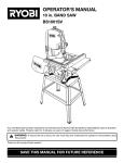
How to Install a sliding gate from EasyGate
Want to install your own automatic sliding gate? EasyGate has all the gear you need to build and install an
automatic sliding gate.
Note: The information on this page is intended as a guide only representing a typical installation. Dimensions will
vary depending on your gate type and running gear setup.
What is the width of the driveway?
Is there sufficient space adjacent the driveway for the gate to slide back onto when open?
Will 240V power be required at the gate or will you install a low voltage system like the EasyGate 24v Boxer motor
which can operate with the 240v upto 100m away or solar powered?
• Is the driveway the only entrance to the property?
If YES - Will a pedestrian gate be required?
If YES - Consider installing battery backup such as the EasyGate Boxer motor to ensure your gate remains
operational if you have a power blackout.
• Is there a fall across the driveway from left to right? I.e. is the ground under the gate level?
To workout the fall run a string line that is level across the driveway and check the difference at each end. If you
have a significant fall you will need to add a minimum 25% extra in your weight calculations for the motor.
• What type of design would you like for your gates? You can view some of EasyGate gate designs. Click on “Sliding
Gates” under the main picture of the home page.
• Estimate the approximate weight of the gate. Take into consideration that with solid gates (sheeted gates you
can't see through) the power needed to drive the gate increases because of the increased weight and wind load
(friction) on the gate. Allow a minimum 25% extra in your weight calculations. The average person can lift 70 kgs so
4 people will lift 280kgs. This is a medium gate. Gates over 400kgs are considered heavy and gates under 200kgs are
light. EasyGate alloy gates are light to medium but very strong so the Boxer motor will push it with ease.
• What surface is the driveway?
The surface needs to be continuous concrete for double the width of the driveway and generally 200-250mm
across. The depth of the footing will be dependent on soil conditions and traffic weights.
• Things to consider when you are having your gate built; Aluminium gates are light weight, strong and will not
corrode in hash conditions such as sea side locations. They are easy to install and will not need expensive heavy duty
openers and are easy on the running gear wear and tear. Steel gates are strong but heavy and need to be zinc
coated prior to powder coating if you want them to last as long as alloy. The bottom rail needs to be no less than
75mm high. EasyGate Manor gates have a 100mm x 50mm bottom section and are made from aluminium.
• A support post of no less than 75x75 RHS is required, preferably 100 x100 and concreted into the ground.
• Ensure a catcher bracket is installed in the closed position and a top guide bracket fitted to the top of the post
above your automation motor to hold the gate vertical. This will help prevent it being pushed over. Always install a
stopper at the bottom of the gate in the fully open position to prevent over running.
Basically the gate must run well manually before installing automation. The test we use is that you must be able to
1
open the gate with two fingers while slowly walking (on level ground). If your installation is on a slope please ring
EasyGate on 0800 774636 to discuss what will work best.
• Do you want the gate to automatically close behind you when you drive in or out? All EasyGate gate openers have
this feature.
If NO - you will press your hand transmitter once to open the gate and then press it again to close it.
If YES - a conduit will need to be installed between the motor position and the catch post. If this is not possible a
5mm slot will need to be cut into the concrete parallel to the edge of the sliding gate track. This will allow for the
installation of optional Safety Beams which will prevent the gate closing on obstacles such as you car.
• How will visitors enter or let you know they have arrived if there is no pedestrian entry?
We recommend the EasyGate Keypad for the outside of the property and the EasyGate Exit Button on the inside of
the property as standard. Place your mobile number next to the keypad (plastic name badge will do fine) and the
visitor can ring you for access. Audio/Visual Intercom - you can have a combination of video monitors and audio
handsets to suit your requirements. We recommend the EasyGate Kocom Audio intercom
• Do you need access back out through the gate without your remote control while gardening or walking the dog?
A keypad is a good option here as with the entry but a keyed exit button is also a common addition placed inside
your property so that you can press it from the car window.
In-depth look at Planning a sliding gate installation;
The more time you spend at this stage the less mistakes are made and time wasted doing re-work, so spend a bit of
time getting this part right. Any sliding gate has only a few key points that need consideration - the track, the gate,
guide support post or pier, receiver post or pier and the catcher. Granted, the automation section has many more
considerations but just for the moment let's concentrate our planning on the basics as they remain constant whether
the gate is automated or not.
The first thing we need is two definable points to determine our gate opening. You may have existing posts, brick or
concrete piers. If not you will need to allow for the installation of posts or piers to act as a receiver or catcher on
closing and guide support bracket to stop the gate from falling over.
If you are installing new posts I would suggest 75mm -100 mm square as a good size and if concreting into the
ground a minimum of 600mm in concrete with legs attached.
2
Once we have determined our two points we can start to look for and record some information 1. The opening width between our two posts or piers.
2. This will give us a width for our gate called the FRAME LENGTH - usually this is the opening width plus 50mm
overlap on the receiver side plus overlap on the guide / roller side, typically 100mm for a manual gate or 300mm for
an automated gate.
3. Once we have a total gate width we can check to ensure sufficient room to slide open fully without impeding the
opening.
Now that we have worked out where our gate will slide we can determine the track position. The track centre will
run approx. 75mm from the face of your posts or piers when using a standard EasyGate of 50mm thick. When your
gate is thicker than this you will need to adjust the track centre to suit.
Concreting In Posts;
Sounds simple enough I hear you say but poorly installed posts account for 90% of all gate problems. If the post moves,
the gate fails – it’s that simple!
Start with your post. As a good guide one third of your post should be in the ground. In other words if the finished gate
post is 1800 high from the ground your total length is now 2400. A minimum of 600mm should be in the ground.
Fit a leg or two to your post. A post without any cross braces or legs to anchor the post in the concrete will simply slide
out of the concrete when dry or worse still may sink down if no concrete has been put underneath. Put at least on
decent cross brace about 300mm up your post and about 150mm wide or place a tile under the post.
Dig your hole deep, not round. A common mistake is to dig a one metre by one metre hole but only 400mm deep. Do
not. 400mm x 400mm x 1000mm deep is much better and takes less than half the concrete.
The simplest way to mix your concrete is to buy the premix concrete packs at your local hardware. They are
inexpensive, the mix is accurate and strong and they only take 5 minutes to mix in a bucket. Just add water. Most posts
require about four 35kg bags. DO NOT USE QUICKSET, RAPIDSET OR ANY OTHER FAST DRYING CONCRETE. These work
fine in static fence posts but will quickly come unstuck when a big hinged gate starts swinging on the post. Where they
can be handy is your very first mix in the bottom of the hole. This allows you to set your height and squareness while
the concrete sets and stops any further movement whilst you complete your concreting.
Gate Construction;
We will cover here basic, or more correctly, common gate construction. There are countless ways to construct your
gate that would take a complete book if you included drawings etc.
The easiest place to start is the bottom rail of the gate. The bottom rail is generally 100x50mm RHS such as the
EasyGate Manor Gates. This will give you more overall strength and added room if installing your motors gear rack at
the bottom although 50x50mm RHS is perfectly acceptable on short gates under 3.5m. Light weight gates can be
made from 1.6mm wall thickness whilst wide gates should be 2.5mm -3mm wall thickness such as the EasyGate
manor gates. Sides and top are typically 50x50mm.Gate fill is obviously a personal choice. A gate using a centre fill
contained within the main frame and a gate using a front surface mounted fill like pickets or spears.
A pair of wheels will need to be installed at 25% in from each end of the gate. There are 2 types of wheels available.
Trapeze (high profile) is a wheel that bolts directly under your gate while Support (low profile) wheels need to be
inserted into your bottom spin rail of the gate so only a portion of the wheel is exposed. 80mm diameter wheels for
short (under 3.5m) light gates and 100mm for larger heavy gates. You have a choice of V shape or U shape depending
on your personal preference but U shape is better suited to driveways with small stones then V but apart from that
they will both do the job.
How to fit wheels to your sliding gate
To attach the wheels to the gate you must decide on a suitable position you wish to place the wheel in from the end.
3
The most common is about 1m and in the centre of the vertical round bars. If your concrete is uneven then you may
need to go further in so as the centre of the gate does not hit the wheel track.
Option 1: Support Wheel
Depending on the position of the cradle determines the width of the cut hole in the gate. Note: EasyGate sliders are
supplied with the wheel space already cut and wheels fitted. Only cut a rectangle hole big enough to fit the portion
of the wheel required. This is done using a simple hand grinder with a cut off blade once you have marked the hole
with a marker or tape. Place the gate at 45 degrees on 2 x trestles so you can safely cut the holes. Be sure to protect
the gate from damage with soft mats or do it on grass. When cutting the hole you will not need to cut right up to the
corners with alloy but near enough...use a hammer and punch to tap the excess rectangle into the gate and remove
it once free from the corners. Fit the wheel into the hole and check for free running. Use standard fasteners to
secure the wheel to the gate.
Option 2: Trapeze Wheel
Track basics;
Perhaps the two most basic fundamentals of a sliding gate are a) straight and b) consistent. I say consistent because
it is not necessary for a track to be level left to right, but it must be consistent. In other words, if your driveway has a
consistent drop from one side to the other of say 200mm, then the run off portion of your track must also fall
200mm so that the entire track, which is twice the length of your gate opening falls a consistent 400mm. No rises
and falls but a smooth, consistent drop.
Straight is pretty much common sense. The centre of your track should generally be about 80-100mm from your
guiding post or pier for a 50mm thick gate. This dimension will vary dependent on your gate thickness roller
configuration.
What type of track;
1.
Bolt Down Track; By far the most preferred method and is what all EasyGate sliders come with. This type of track
assumes you have a surface suitable to bolt down to. Usually an existing concrete driveway or in some rare cases
well secured and level brick paving will suffice if traffic flow is not heavy or constant. Most professional installers
prefer to lay a full concrete plinth and then bolt down the track. Their argument is that using bolt down track
gives them flexibility and allows a section to be replaced if damaged. When bolted down to an existing driveway
it is not unusual to see the back edge of the track or "run off" section with brackets or legs at 500mm intervals
4
either bolted to an existing wall or concreted at footing points (see photo below). This is acceptable in most
cases as there will be no traffic over this section and will carry the gate only. To secure your wheel track
EasyGate provide concrete anchor pins with your gate and even include the drill bit!
2. Full concrete plinth allowing for driveway completion; This is simply a concrete plinth poured to give allowance for
driveway finishing and be the foundation to your wheel track, be it a brick paving header course or Asphalt etc. A few
different levels can be used to achieve different finished results (see below). This track has maximum strength due to
the reinforcing and the run off area of the track is also well supported by the reinforcing.
Guide Bracket;
Once the wheel track is positioned you can install the guide bracket above the gate. Positioned on the post behind
the motor this bracket is to prevent the gate from falling over and guide it left and right. For small light gates less
then 3.1m a 2 x roller guide bracket will do and a 4 x roller for all others.
Gate Catcher or receiver;
Positioned on the post at the closed gate end the Gate Catcher guides the gate to the closed position and prevents
the gate from being lifted off the track. There are 2 types of gate catchers. The standard butt catcher is used for
positions that the gate will butt upto the post and the side mountable catcher for gates that will pass the end post
which are positioned in-line with the centre post. The EasyGate Side Catcher is fitted with 2 rollers and can be
adjusted up and down as well as sideways giving a higher level of installation options.
Gate Stopper; Positioned on the ground to the rear of the fully open gate to stop the gate running off the wheel
track or guide bracket. This is an important safety device that should be installed.
5
6
7
Do not fit wheels in the middle of the gate. If the ground drops off the edge of the driveway a steel rail can be used
to support the gate track.
Guide systems for Sliding Gates
8
Sliding Gates require a guide system to hold the gate up as it moves, the simplest being a guide roller either side of the gate.
Open Hard Stopper
The gate must also be prevented gate over running off the guide system and fall over, which can be dangerous and damaging.
9
Mounting your motor and gear rack;
The most common method of motor mounting is to bolt down to a pre prepared concrete pad although most motors
have a base plate available that can be installed in concrete beforehand with your track work making the bolt down
procedure even simpler. Use a length of rack to position your motor in relation to the gate and take into account
limit switch positioning.
Once you have bolted the motor down securely use your manual override to put the gate into manual mode. Start at
one end and use tek screws (supplied) to fasten your first length of rack centred over the pinion or sprocket. The rack
should not sit directly on the pinion but have a 1-1.2mm gap between the pinion and the rack. Use a 1-1.2mm
spacing washer under the 4 corners of the motor base plate while installing the gear rack, then remove these to do
the final setup. Slide the gate back and forth to ensure the first length is level. You can now slide the gate along until
the pinion is about 80mm from the end of the first length of rack. Attach the next length of rack into the interlocking
point of the first length of rack and position the other end of the rack on the pinion. You should now be able to
fasten this length of rack at two points and move along to the next and subsequent lengths. You may need to cut the
last length to suit. When all lengths are fitted, remove the spacing washers and re tighten the motor to the ground.
Check the operation of the rack before inserting all fasteners.
Ready to power and program;
At this point I assume you have had your power connected and all other wiring has been completed. My simple
suggestion here is that you leave most extras like photo cell beams and keypads not connected, and have all required
control board connector block wire loops installed until after you finish programming and have your gate running
smoothly. Having bells and whistles connected will only complicate matters if things don't go exactly as expected. By
having the bare basics makes fault finding much easier.
For further information please visit the EasyGate website www.easygate.co.nz
Email [email protected]. Ph. 0800 774636
10