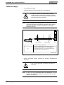
1
engineering mannesmann Rexroth ECODRIVE Drive Controller DKC02.1 Trouble Shooting Guide: SSE 03VRS DOK-ECODRV-SSE-03VRS**-WAR1-EN-P 274828 Indramat ECODRIVE Drive Controller DKC02.1 Title Type of Documentation ECODRIVE Drive Controller DKC02.1 Trouble Shooting Guide Documentation Code DOK-ECODRV-SSE-03VRS**-WAR1-EN-P Internal file reference • Map 57-03V-EN Register 9 • 209-0073-4324-00 The purpose of this documentation? This documentation assists maintenance personnel in identifying errors with equipment. It should: • help in understanding error messages • help in finding the causes for defects • describe the procedure for error recovery • simplify the process of establishing contact with the INDRAMAT customer service department. Editing Sequence Copyright This documentation is intended as a switch board panel supplement for the machine manufacturer. Document identification of previous and current releases Release date Remarks DOK-ECODRV-SSE-03VRS**-WAR1-EN-P 12/96 First release INDRAMAT GmbH, 1997 Copying this document, and giving it to others or the use or communication of the contents thereof without express authority, are forbidden. Offenders are liable for the payment of damage. All rights are reserved in the event of the grant of a patent or the registration of a utility model or design (DIN 34-1). Validity Published by All rights are reserved with respect to the content of this documentation and the availability of the product. INDRAMAT GmbH • Bgm.-Dr.-Nebel-Str. 2 • D-97816 Lohr a. Main Telefon 09352/40-0 • Tx 689421 • Fax 09352/40-4885 Dept. END (GB/OS) About this Documentation DOK-ECODRV-SSE-03VRS**-WAR1-EN-P • 12.96 ECODRIVE Drive Controller DKC02.1 Contents 1 Diagnostic Message Descriptions 1-1 1.1 Overview of Diagnostic Message Descriptions ....................................................................................1-1 Diagnostic Message Types............................................................................................................1-1 Makeup of a Diagnostic Message..................................................................................................1-1 2 Error Diagnostic Messages 2-1 UL Motor Type not registered ........................................................................................................2-1 PL Load parameter default values.................................................................................................2-1 F207 Switching to uninitialized operation mode.............................................................................2-2 F218 Heatsink Overtemperature Shutdown ..................................................................................2-2 F219 Motor Overtemperature Shutdown .......................................................................................2-3 F220 Bleeder Overtemperature Shutdown ....................................................................................2-3 F226 Undervoltage Error ...............................................................................................................2-4 F228 Excessive Deviation .............................................................................................................2-4 F229 Motor Encoder Failure: Quadrant Error ................................................................................2-5 F234 Emergency Stop ...................................................................................................................2-5 F236 Excessive Position Feedback Difference .............................................................................2-5 F237 Excessive Position Command Difference ............................................................................2-6 F242 External Encoder Failure: Signals too small.........................................................................2-6 F245 External Encoder Failure: Quadrant Error ............................................................................2-7 F248 Low Battery Voltage..............................................................................................................2-7 F267 Erroneous Internal Hardware Synchronization.....................................................................2-8 F276 Absolute encoder error > P-0-0097 ......................................................................................2-8 F401 Double MST Error Shutdown................................................................................................2-9 F402 Double MDT Error Shutdown ...............................................................................................2-9 F403 Invalid Communication Phase Shutdown .............................................................................2-9 F404 Error during Phase Progression .........................................................................................2-10 F405 Error during Phase Regression ..........................................................................................2-10 F406 Phase Switching Without Ready Signal .............................................................................2-10 F629 Positive Travel Limit Value is Exceeded.............................................................................2-10 F630 Negative Travel Limit Value is Exceeded ...........................................................................2-11 F643 Positive Travel Limit Switch Detected ................................................................................2-12 F644 Negative Travel Limit Switch Detected...............................................................................2-12 F822 Motor Encoder Failure: Signals too Small ..........................................................................2-13 F860 Overcurrent: Short in Power Stage.....................................................................................2-13 F870 + 24 Volt Error ....................................................................................................................2-13 F873 Power supply drive stage fault............................................................................................2-14 F878 Velocity Loop Error .............................................................................................................2-14 DOK-ECODRV-SSE-03VRS**-WAR1-EN-P • 12.96 Contents I ECODRIVE Drive Controller DKC02.1 F879, Crossing Velocity Limit (S-0-0091) Value..........................................................................2-15 F895 4 kHz Fault .........................................................................................................................2-15 3 Warning Diagnostic Messages 3-1 E249 Positioning vel. (S-0-0259) greater S-0-0091.......................................................................3-1 E250 Drive Overtemperature Warning ..........................................................................................3-1 E251 Motor Overtemperature Warning .........................................................................................3-1 E252 Bleeder Overtemperature Warning ......................................................................................3-2 E253 Target position out of travel zone .........................................................................................3-2 E254 Not Homed ...........................................................................................................................3-2 E255 Feedrate Override(S-0-0108) = 0.........................................................................................3-3 E256 Torque Limit = 0 ...................................................................................................................3-3 E257 Continuous Current Limiting Active ......................................................................................3-3 E259 Command velocity limitation active ......................................................................................3-4 E410 Slave not scanned or address 0...........................................................................................3-4 E825 Overvoltage in the Power Stage...........................................................................................3-4 E829 Positive Position Limit Value Exceeded ...............................................................................3-5 E830 Negative Position Limit Value Exceeded..............................................................................3-5 E843 Positive Travel Zone Limit Switch Activated.........................................................................3-5 E844 Negative Travel Zone Limit Switch Activated .......................................................................3-6 4 Command Diagnostic Messages 4-1 C100 Communication phase 3 transition check ............................................................................4-1 C101 Invalid Communication Parameter (S-0-0021).....................................................................4-1 C102 Limit Error Communication Parameter (S-0-0021) .............................................................4-1 C104 Config. IDN for MDT not configurable ..................................................................................4-1 C105 Configured Length > Max. Length for MDT..........................................................................4-2 C106 N for AT not configurable .....................................................................................................4-2 C107 Configured Length > Max. Length for AT.............................................................................4-2 C108 Time Slot Parameter > SERCOS Cycle Time......................................................................4-3 C109 Position of Data Record in MDT (S-0-0009) even................................................................4-3 C110 Length of MDT (S-0-0010) odd ............................................................................................4-3 C111 ID9 + Record Length - 1 > Length MDT (S-0-0010).............................................................4-4 C112 TNcyc (S-0-0001) or TScyc (S-0-0002) Error ......................................................................4-4 C113 Relation TNcyc (S-0-0001) to TScyc (S-0-0002) Error ........................................................4-4 C114 T4 > TScyc (S-0-0002) - T4min (S-0-0005) .........................................................................4-5 C115 T2 too small..........................................................................................................................4-5 C200 Communication phase 4 transition check ............................................................................4-5 C201 Invalid Parameter (-> S-0-0022) ..........................................................................................4-5 C202 Limit Error Parameter (->S-0-0022) .....................................................................................4-6 C203 Parameter Calculation Error (->S-0-0022) ...........................................................................4-6 C207 Load Error LCA ...................................................................................................................4-6 C210 External Feedback Required (-> S-0-0022) .........................................................................4-6 C211 Invalid Feedback Data (-> S-0-0022)...................................................................................4-7 C212 Invalid amplifier data (-> S-0-0022)......................................................................................4-7 C213 Position data scaling error....................................................................................................4-7 C214 Velocity data scaling error....................................................................................................4-8 II Contents DOK-ECODRV-SSE-03VRS**-WAR1-EN-P • 12.96 ECODRIVE Drive Controller DKC02.1 C215 Acceleration data scaling error.............................................................................................4-8 C216 Torque/force data scaling error ............................................................................................4-9 C217 Motor feedback data reading error.......................................................................................4-9 C218 External feedback data reading error...................................................................................4-9 C220 Mot. Feedback Initialization Error.......................................................................................4-10 C221 Ext. Feedback Initializing Error ..........................................................................................4-10 C227 Modulo range error.............................................................................................................4-11 C300 Set absolute measuring .....................................................................................................4-11 C301 Setting Absolute Measuring Not Allowed, Drive Enable.....................................................4-11 C302 Absolute Measuring System Not Installed .........................................................................4-11 C500 Reset class 1 diagnostic ....................................................................................................4-12 C600 Drive-controlled homing procedure command ...................................................................4-12 C601 Homing Not Possible If Drive Is Not Enabled.....................................................................4-12 C602 Distance homing switch - reference mark erroneous ........................................................4-12 C603 Homing Not Permitted In This Operating Mode .................................................................4-12 C604 Homing of absolute encoder not possible ..........................................................................4-13 C605, Homing velocity too great..................................................................................................4-13 C700 Basic load...........................................................................................................................4-13 C800 Command Base-Parameter load .......................................................................................4-13 D400 Positive stop drive procedure command ............................................................................4-14 D401 ZKL1 Error at Command Start ...........................................................................................4-14 5 Status Diagnostic Messages 5-1 A000 Communication Phase 0 ......................................................................................................5-1 A001 Communication Phase 1 ......................................................................................................5-1 A002 Communication Phase 2 ......................................................................................................5-1 A003 Communication Phase 3 ......................................................................................................5-2 A010 Halt Drive..............................................................................................................................5-2 A012 Control and Power Sections Ready for Operation................................................................5-2 A013 Ready for Power ON ............................................................................................................5-2 A100 Drive in Torque Mode...........................................................................................................5-2 A101 Drive in Velocity Mode..........................................................................................................5-3 A102 Position Mode Encoder 1 .....................................................................................................5-3 A103 Position Mode Encoder 2 .....................................................................................................5-3 A104 Position Mode Encoder 1 / lagless positioning.....................................................................5-3 A105 Position Mode Encoder 2 / lagless positioning.....................................................................5-3 A106 Drive-Controlled Interpolation/Encoder 1 .............................................................................5-4 A107 Drive-Controlled Interpolation/Encoder 2 .............................................................................5-4 A108 Drive-Controlled Interpolation/Encoder 1/Lagless................................................................5-4 A109 Drive-Controlled Interpolation/Encoder 2/Lagless................................................................5-4 6 Exchanging Drive Components 6-1 6.1 Procedure for Exchanging Devices ......................................................................................................6-2 Exchange the DKC: .......................................................................................................................6-3 Motor Exchange:............................................................................................................................6-3 Cable Exchange: ...........................................................................................................................6-4 DOK-ECODRV-SSE-03VRS**-WAR1-EN-P • 12.96 Contents III ECODRIVE Drive Controller DKC02.1 IV Contents DOK-ECODRV-SSE-03VRS**-WAR1-EN-P • 12.96 ECODRIVE Drive Controller DKC02.1 1 Diagnostic Message Descriptions 1.1 Overview of Diagnostic Message Descriptions Diagnostic Message Types Each operational state of the drive controller is characterized by a diagnostic message. Note the following distinctions: Error diagnostic messages Warning diagnostic messages Command diagnostic messages Status diagnostic messages Operation status messages Makeup of a Diagnostic Message A diagnostic message consists of: • A diagnostic number and • a diagnostic text F2/28 excessive output error diagnostic text diagnostic number Fig. 1-1: Diagnostic message makeup: a diagnostic message number and text. In the example shown above, "F2" and "28" alternate in the H1 display. Parameter P-0-0001, Diagnostic number appears in hexadecimal form. Also, the drive controller stores the diagnostic number and diagnostic text as the string "F2/28, Excessive output error" in parameter S-0-0095, Diagnostic message. DOK-ECODRV-SSE-03VRS**-WAR1-EN-P • 12.96 Diagnostic Message Descriptions 1-1 ECODRIVE Drive Controller DKC02.1 H1-Display The H1-Display serves as an optical display of the diagnostic message on the drive controller. H1 DISPLAY EK0003d1.ds4 Fig. 1-2: H1-Display An icon representing the diagnostic number appears on this two-place seven-segment display. The arrangement of the display is based on the "Diagnostic message priority display" screen. This display allows you to see the current operation status at a glance, without using a communications interface. The operating mode cannot be seen from the H1-Display. If the drive is enabled and no command was activated, then the symbol "AF" appears on the display. 1-2 Diagnostic Message Descriptions DOK-ECODRV-SSE-03VRS**-WAR1-EN-P • 12.96 ECODRIVE Drive Controller DKC02.1 Diagnostic message output priority If more than one diagnostic message has been generated, then the message with the highest priority will be displayed first. The illustration below shows the order of priority. Error 3 5 , 2 5 , 7 < Warning Command error Command active yes Ready to operate ? no Drive lock active Ready to operate Communication phase Drive ready Drive Halt Drive enable Fig. 1-3: Diagnostic message priority Plain text diagnostic message Plain text diagnostic messages contain the diagnostic number followed by the diagnostic text, as shown in the example, "Excessive output error" (Fig. 1-1). It can be read from parameter S-0-0095, Diagnostic message and displays the drive status directly to the user interface. The plain text diagnostic message will be shown in the current language as set in language selection. DOK-ECODRV-SSE-03VRS**-WAR1-EN-P • 12.96 Diagnostic Message Descriptions 1-3 ECODRIVE Drive Controller DKC02.1 Notes 1-4 Diagnostic Message Descriptions DOK-ECODRV-SSE-03VRS**-WAR1-EN-P • 12.96 ECODRIVE Drive Controller DKC02.1 2 UL Error Diagnostic Messages Motor Type not registered Description: The controller settings for current controller, speed controller and position controller are stored in the motor feedback. When the controller is connected to the motor for the first time, the controller indicates that the controller settings are not correct for that motor type. When the "initial program loading" command is started, the default settings from the feedback storage are loaded into the drive controller. Pressing the S1 button on the drive controller starts the "initial program loading" command. Cause: The motor has been replaced. A parameter file has been loaded in which the parameter P-0-4036, Contacted Motor Type and the motor type are different. Remedial action: Start command "C700 initial program loading" or press S1 button. PL Load parameter default values Description: After the firmware (EPROMs) has been replaced, the drive shows "PL" if parameters are different in the old and the new firmware. Pressing the S1 button on the drive controller or starting the command "load base parameters" clears all parameter values and sets the parameters to their default values. Cause: The firmware has been replaced; the number of parameter in the new firmware is different from the number of parameters in the old firmware. Remedial action: Press S1 on the drive controller. This clears all parameter values and sets the parameters to their factory-set default values. ⇒ This overwrites all parameters and motion blocks. CAUTION DOK-ECODRV-SSE-03VRS**-WAR1-EN-P • 12.96 Error Diagnostic Messages 2-1 ECODRIVE Drive Controller DKC02.1 F207 Switching to uninitialized operation mode Cause: "0" has been programmed in at least one of the four mode parameters S0-0032..35. This mode has been selected by bits 8 and 9 in the master control word while the drive controller was activated. Remedial action: Enter the required mode in the activated mode parameter. Valid modes are: Meaning: Bit list of mode parameters: Torque control 0000 0000 0000 0001 Velocity control 0000 0000 0000 0010 Position control with position feedback value 1 0000 0000 0000 x011 Position control with position feedback value 2 0000 0000 0000 x100 Drive-internal interpolation with position feedback value 1 0000 0000 0001 x011 Drive-internal interpolation with position feedback value 2 0000 0000 0001 x100 Fig. 2-1: Modes Parameter: Primary mode S-0-0032 Secondary mode 1 S-0-0033 Secondary mode 2 S-0-0034 Secondary mode 3 S-0-0035 Verify that a valid interpolation type has been entered. F218 Heatsink Overtemperature Shutdown Description: The heat sink temperature of the DKCs is monitored. The unit is switched off to prevent damage if the heat sink temperature is too high. Cause: 2-2 Error Diagnostic Messages 1. The ambient temperature is too high. The specified performance characteristics are valid up to an ambient temperature of 45°C. 2. The heat sink of the DKC is polluted. 3. Other modules or cabinet installation prevent convection. 4. Fan defective DOK-ECODRV-SSE-03VRS**-WAR1-EN-P • 12.96 ECODRIVE Drive Controller DKC02.1 Remedial action: Ref. 1. Reduce ambient temperature (provide cooling for the switchgear cabinet, for example) Ref. 2. Clean the heat sink Ref. 3. Install the unit in a vertical position and provide sufficient clearance for the ventilation of the heat sink. Ref. 4. Replace the unit F219 Motor Overtemperature Shutdown The drive generates this error message when the motor temperature exceeds 150°C. Cause: 1. Motor overload. The effective torque requested from the motor has exceeded the permissible continuous torque value for too long a time. 2. Broken wire or short-circuit in the cable to the motor temperature monitor. 3. Instability in the speed control loop. Remedial action: Ref. 1. Verify motor rating. Check whether the drive conditions of a system that has been used for a long time have changed in the meantime (pollution, friction, moved masses, etc.). Ref. 2. Check the cable to the motor temperature monitor (X6/1 and X6/2) for broken wires or short-circuit. Ref. 3. Check the parameter values of the speed control loop (see Functional Description). F220 Bleeder Overtemperature Shutdown Description: Overload of the built-in brake resistance. The drive is shut down after braking if the maximum braking energy is exceeded. This protects the bleeder from thermal destruction. Cause: 1. The energy returned from the mechanical system of the machine via the motor is too high. Remedial action: Ref. 1. Too much power ---> reduce acceleration values Too much energy ---> reduce velocity values Verify drive rating Install additional bleeder module if necessary DOK-ECODRV-SSE-03VRS**-WAR1-EN-P • 12.96 Error Diagnostic Messages 2-3 ECODRIVE Drive Controller DKC02.1 F226 Undervoltage Error The DC bus voltage is monitored. The drive is shut down after the selected error reaction when the voltage falls below the minimum threshold. Cause: 1. Power shutdown without previous de-activation of the drive via the controller enable signal (RF) 2. Activating the drive via the controller enable signal (RF) without previous activation of the power section. 3. Malfunction of the power supply. Remedial action: 1. Verification of the logic required for activating the drive in the connected controller. 2. Malfunctions in the power supply must be eliminated. F228 Excessive Deviation When the position control loop in the drive is closed, it checks whether the specified command value can be followed. A model position feedback value is computed in the drive and compared with the actual position feedback value. This error is generated if the difference between theoretical and actual position feedback value exceeds the value of the parameter S-0-0159, Monitoring Window for more than 64 ms. Cause: 1. The acceleration capacity of the drive has been exceeded. 2. The axis has been blocked. 3. Incorrect values in the drive parameters. 4. Incorrect value of S-0-0159, Monitoring Window 5. The power supply was switched off while the controller enable signal was applied. Remedial action: Ref. 1. Check the parameter S-0-0092, Bipolar Torque/Force Limit Value and set it to the maximum value that is permissible for the application. Reduce the specified acceleration value of the controller (see Controller Manual). Ref. 2. Check the mechanical system and eliminate axis jamming Ref. 3. Check drive parameters Ref. 4. Set S-0-0159, Monitoring Window Ref. 5. Check if there are error messages different to "28" in the AC servo drive. 2-4 Error Diagnostic Messages DOK-ECODRV-SSE-03VRS**-WAR1-EN-P • 12.96 ECODRIVE Drive Controller DKC02.1 F229 Motor Encoder Failure: Quadrant Error A hardware error was detected in the employed motor encoder interface. Cause: 1. Defective encoder cable 2. Interference on encoder cable 3. Defective motor encoder interface 4. Defective drive controller Remedial action: Ref. 1. Replace the encoder cable Ref. 2. Lay the encoder cable separately from power cables Ref. 3. Replace the motor encoder interface Ref. 4. Replace the drive controller F234 Emergency Stop Cause: The emergency stop function has been triggered by switching off the +24 V signal art the emergency stop input. The drive was shut down with the selected error reaction. Remedial action: 1. Eliminate the cause that has switched off the +24 V signal at the emergency stop input. 2. Activate the command "Reset class 1 diagnostics" via the controller (see Controller Manual). F236 Excessive Position Feedback Difference Cause: Position feedback value 1 and position feedback value 2 are set to the same value and the cyclic evaluation of both encoders is started in the communication phase 4 transition check command. In cyclic operation (phase 4), the position feedback value difference of both encoders is compared with S-0-0391, Monitoring Window External Feedback. The error F236, Excessive Position Feedback Difference is issued and the programmed error reaction performed if the value of the difference exceeds the monitoring window. 1. Incorrect parameter for external encoder (S-0-0115, Position feedback 2 type parameter S-0-0117, Resolution of rotational feedback 2. Incorrect parameter values for mechanical system between motor shaft and external encoder (S-0-0121, Input revolutions of load gear S-0-0122, Output revolutions of load gear S-0-0123, Feed constant) DOK-ECODRV-SSE-03VRS**-WAR1-EN-P • 12.96 Error Diagnostic Messages 2-5 ECODRIVE Drive Controller DKC02.1 3. The mechanical system between motor shaft and external encoder is not rigid (e.g. gear play) 4. Defective encoder cable 5. Defect in signal conditioning of external measuring system 6. Maximum input frequency of encoder interface exceeded 7. External encoder not mounted on driven axis Remedial action: Ref. 1. Check S-0-0115, Position feedback 2 type parameter and S-0-0117, Resolution of rotational feedback Ref. 2. Check S-0-0121, Input revolutions of load gear, S-0-0122, Output revolutions of load gear, and S-0-0123, Feed constant Ref. 3. Increase S-0-0391, Monitoring Window External Feedback Ref. 4. Replace encoder cable Ref. 5. Replace axis controller Ref. 6. Reduce velocity Ref. 7. Set S-0-0391, Monitoring Window External Feedback to 0 (deactivate monitoring function) F237 Excessive Position Command Difference Cause: The position command values that arrive via the SERCOS interface are monitored when the drive works in position control mode. The position command value monitoring function responds if two consecutive position command values require the drive to provide a velocity that is equal to or greater than the value specified in S-0-0091, Bipolar Velocity Limit Value. While the excessive position command value is stored in parameter P-0-0010, the last valid position command value is stored in parameter P-0-0011. Remedial action: Compare S-0-0091, Bipolar Velocity Limit Value with the programmed velocity and adjust if necessary. F242 External Encoder Failure: Signals too small Cause: In the high-resolution evaluation of an external measuring system, the analog signals of the measuring system are employed for monitoring the sine and cosine signal. Remedial action: • Check the cables to the measuring system • Check the measuring system 2-6 Error Diagnostic Messages DOK-ECODRV-SSE-03VRS**-WAR1-EN-P • 12.96 ECODRIVE Drive Controller DKC02.1 F245 External Encoder Failure: Quadrant Error A hardware fault has been detected in the external measuring system’s high-resolution position interface for sinusoidal signals. Cause: 1. 2. 3. Defective encoder cable Interference on encoder cable Defective amplifier Remedial action: Ref. 1. Replace the encoder cable Ref. 2. Lay the encoder cable separately from power cables Ref. 3. Replace the amplifier F248 Low Battery Voltage Cause: In a motor of the MKD series, the absolute position information is stored in a battery-backed electronics system in the motor feedback. The battery has been designed for a utilization period of 10 years. This message is output if the battery voltage drops below 2.8 V. The function of the absolute encoder is ensured for another two weeks. CAUTION Hazard: Faults in controlling motors and/or moved elements may lead to injuries. ⇒ Action: Replace battery as soon as possible Preparation for changing batteries The following parts are required: • Size 10 TORX screwdriver • Flat nose pliers; torque wrench • New pre-assembled battery (order no.: 257101) CAUTION Hazard: Faults in controlling motors and/or moved elements may lead to injuries. ⇒ Switch off the power supply and secure it against being switched on again. Replace the battery while the control voltage is switched on. If the control voltage were switched off while the battery is disconnected, the right reference point would be lost and must be re-established. DOK-ECODRV-SSE-03VRS**-WAR1-EN-P • 12.96 Error Diagnostic Messages 2-7 ECODRIVE Drive Controller DKC02.1 Removing the battery: • Use a size 10 screwdriver to remove the TORX screws 1 • Pull out the cover of the RSF resolver feedback • Remove connector 2 of the battery • Loosen battery clamp 3 and remove battery Inserting the battery • Insert the pre-assembled battery (order no.: 257101) in the enclosure and tighten the clamping device. • Caution! Do not squeeze the battery cable • Reconnect battery connector 2 Close the cover of the resolver feedback, insert the 4 TORX screws and use the torque wrench to tighten them (1.8 Nm) F267 Erroneous Internal Hardware Synchronization Cause: A phase control loop synchronizes the drive control activities of all drives that are connected to a SERCOS loop. Proper synchronization is monitored. This error is generated if the average deviation exceeds 7 µs. Remedial action: Replace drive controller F276 Absolute encoder error > P-0-0097 The current actual position is saved when a drive controller with an absolute encoder motor (multi-turn) is switched off. When it is switched back on, the position that is determined by the absolute encoder evaluation is compared with the stored value. This error is generated if the deviation exceeds the programmed value of P-0-0097, Monitoring Window abs. Encoder. Cause: 1. First-time activation after the motor has been replaced, for example (saved position is invalid). 2. The axis is moved in de-activated state by more than the distance that has been selected in P-0-0097, Monitoring Window abs. Encoder. 3. Incorrect position initialization. Remedial action: Ref. 1. Clear the error (establish the reference dimension) Ref. 2. The axis is moved while it was switched off, and is outside its valid position. Check whether a new motion command will lead to a damage. Clear the error afterwards. Ref. 3. Hazard by unwanted axis movements. Check the reference dimension. There is a feedback defect if the reference dimension is incorrect. Replace the feedback (complete motor in the case of an absolute motor encoder with MDD or MKD motor). 2-8 Error Diagnostic Messages DOK-ECODRV-SSE-03VRS**-WAR1-EN-P • 12.96 ECODRIVE Drive Controller DKC02.1 F401 Double MST Error Shutdown The drive has not received the master synchronization message frame in two consecutive SERCOS cycles. Cause: 1. Malfunction in the fiber optics cable 2. Excessive damping of the light signals 3. (General) malfunction in the SERCOS interface 4. Master failed Remedial action: Ref. 1. Check all fiber optics connections in the SERCOS loop. Ref. 2. Measure the damping in the fiber optics cables. The maximum damping between TX and RX may not fall below 12,5 dB. Ref. 3. Replace the SERCOS interface module in the drive. Ref. 4. Check the master if all slaves have stopped. F402 Double MDT Error Shutdown The drive has not received the master data message frame (MDT) in two consecutive SERCOS cycles. Cause: 1. Malfunction in the fiber optics cable 2. Excessive damping of the light signals 3. (General) malfunction in the SERCOS interface 4. Failure of the complete bus Remedial action: Ref. 1. Check all fiber optics connections in the SERCOS loop Ref. 2. Measure the damping in the fiber optics cables. The maximum damping between TX and RX may not fall below 12,5 dB. Ref. 3. Replace the SERCOS interface module in the drive Ref. 4. Check the master F403 Invalid Communication Phase Shutdown The SERCOS master module has specified an illegal communication phase (phase > 4). Cause: Error in the controller’s SERCOS master module. Remedial action: Contact the controller manufacturer. DOK-ECODRV-SSE-03VRS**-WAR1-EN-P • 12.96 Error Diagnostic Messages 2-9 ECODRIVE Drive Controller DKC02.1 F404 Error during Phase Progression Phase progression did not follow the required sequence. Cause: Error in the controller’s SERCOS master module Remedial action: Contact the controller manufacturer F405 Error during Phase Regression Regression from a communication phase did not lead to phase 0. Cause: Error in the controller’s SERCOS master module Remedial action: Contact the controller manufacturer F406 Phase Switching Without Ready Signal The SERCOS master has made an attempt to change phases without waiting for the ready message from the drive. Cause: Error in the controller’s SERCOS master module Remedial action: Contact the controller manufacturer F629 Positive Travel Limit Value is Exceeded The drive has been provided with a command value that leads to an axis position outside the positive travel range. The axis has been stopped and the error reaction "set velocity command value to zero" issued. Bit 2 of P0-0090, Travel limit parameter has been set to "Exceeding the travel limit is an error", or a drive control command has been started while the axis limit value is exceeded (e.g. drive-controlled homing). Cause: S-0-0049, Positive position limit value is exceeded. Remedial action: 2-10 Error Diagnostic Messages 1. Check S-0-0049, Positive position limit value 2. Check the controller software limits 3. Activate the axis after the error reaction DOK-ECODRV-SSE-03VRS**-WAR1-EN-P • 12.96 ECODRIVE Drive Controller DKC02.1 Procedure: • Clear the error • Activate power if it has been de-activated • Move the axis to the permissible working range Note: Only command values that lead back into the permissible working range will be accepted. Any other command value will stop the drive again. F630 Negative Travel Limit Value is Exceeded The drive has been provided with a command value that leads to an axis position outside the negative travel range. The axis has been stopped and the error reaction "set velocity command value to zero" issued. Bit 2 of P-0-0090, Travel limit parameter has been set to "Exceeding the travel limit is an error", or a drive control command has been started while the axis limit value is exceeded (e.g. drive-controlled homing). Cause: S-0-0050, Negative position limit value is exceeded. Remedial action: 1. Check S-0-0050, Negative position limit value 2. Check the controller software limits 3. Activate the axis after the error reaction Procedure: • Clear the error • Activate power if it has been de-activated • Move the axis to the permissible working range Note: Only command values that lead back into the permissible working range will be accepted. Any other command value will stop the drive again. DOK-ECODRV-SSE-03VRS**-WAR1-EN-P • 12.96 Error Diagnostic Messages 2-11 ECODRIVE Drive Controller DKC02.1 F643 Positive Travel Limit Switch Detected The positive travel limit switch has been actuated. The axis has been stopped with the error reaction "set velocity command value to zero". Bit 2 of P-0-0090, Travel limit parameter has been set to "Exceeding the travel limit is an error", or a drive control command has been started while the axis limit value is exceeded (e.g. drive-controlled homing). Cause: The positive travel limit switch has been actuated. Remedial action: 1. Reset the error 2. Activate the power supply 3. Move the axis into the permissible working range Note: The drive will not accept any command values that lead further away from the permissible range. Specifying such a command will again result in this error. F644 Negative Travel Limit Switch Detected The negative travel limit switch has been actuated. The axis has been stopped with the error reaction "set velocity command value to zero". Bit 2 of P-0-0090, Travel limit parameter has been set to "Exceeding the travel limit is considered as an error", or a drive control command has been started while the axis limit value is exceeded (e.g. drive-controlled homing). Cause: The negative travel limit switch has been actuated. Remedial action: 1. Reset the error 2. Activate the power supply 3. Move the axis into the permissible working range Note: The drive will not accept any command values that lead further away from the permissible range. Specifying such a command will again result in this error. 2-12 Error Diagnostic Messages DOK-ECODRV-SSE-03VRS**-WAR1-EN-P • 12.96 ECODRIVE Drive Controller DKC02.1 F822 Motor Encoder Failure: Signals too Small The amplitudes of the sine and cosine signals from the motor encoder are monitored. Note: The error cannot be cleared in communication phase 4. Transition to communication phase 2 is necessary before the error can be cleared. Remedial action: • Check the cables . • The signal cables must be laid separately from the motor power cables. The screen must be connected at the drive controller (see Configuration Instructions of the drive controller). • Check the measuring system. Replace it if necessary. F860 Overcurrent: Short in Power Stage The current in the power transistor bridge has exceeded twice the value of the device peak current. The torque of the drive is released at once, and an optional blocking brake is applied immediately. Cause: 1. Short-circuit in the motor cable 2. Defect in the drive controller’s power stage Remedial action: Ref. 1. Check the motor cable for a short-circuit. Ref. 2. Replace the drive controller F870 + 24 Volt Error The drive controller has detected an error in the +24-V supply. Note: The error cannot be cleared. The unit must be switched off. Cause: 1. Short-circuit in the emergency stop circuit 2. 24-V supply is below the minimum value Remedial action: Ref. 1. Check the emergency stop circuit for short-circuit condition Ref. 2. Check the power supply unit. Replace it if necessary. DOK-ECODRV-SSE-03VRS**-WAR1-EN-P • 12.96 Error Diagnostic Messages 2-13 ECODRIVE Drive Controller DKC02.1 F873 Power supply drive stage fault Description: The power supply of the drive stages is monitored. The drive is switched off if the voltage is too low. Cause: 1. The power supply voltage of the driver stages is too low. Remedial action: Ref. 1. Replace the control unit. F878 Velocity Loop Error If, with an active speed control loop, the difference between speed command value and feedback value is greater than 10% of the maximum motor speed, the speed feedback value must change in the direction of the command value. This error is generated if an approach to the command value cannot be detected for more than 20 ms and if the effective torque/force command value is within the limit (= P-0-4046, Active peak current). Cause: 1. Wrong connection of motor cable 2. Power section of drive controller is defective 3. Feedback is defective 4. Incorrect setting of speed controller parameter value 5. Acceleration or deceleration ramp is too steep Remedial action: Ref. 1. Check the motor cable connection Ref. 2. Replace the drive controller Ref. 3. Replace the motor Ref. 4. Check the speed controller according to the application description (see Chapter "Speed controller") Ref. 5. Reduce the maximum acceleration in the controller 2-14 Error Diagnostic Messages DOK-ECODRV-SSE-03VRS**-WAR1-EN-P • 12.96 ECODRIVE Drive Controller DKC02.1 F879, Crossing Velocity Limit (S-0-0091) Value In torque control mode, the actual velocity is monitored. This error is generated if the velocity that has been programmed in the parameter S0-0091, Bipolar Velocity Limit Value is exceeded (1.125-fold value, minimum 100 rpm). Cause: The command torque is higher than the load torque. This causes the actual velocity to be increased up to the maximum possible motor speed. Remedial action: Assign the correct torque command value for the required task. Reduce the parameter S-0-0092, Bipolar Torque/Force Limit Value. F895 4 kHz Fault Description: The 4-kHz signal that is used for producing the resolver signals is synchronized with software processing. This error message is generated in the case of a synchronization error. Cause: 1. Incorrect synchronization of resolver excitation voltage and software 2. The error could be caused by an electrostatic discharge. Remedial action: Ref. 1. Replace the drive controller and return it to the factory for inspection Ref. 2 Cycle the power to all units off and back on. If this does not lead to a positive result: Replace the drive controller and return it to the factory for inspection DOK-ECODRV-SSE-03VRS**-WAR1-EN-P • 12.96 Error Diagnostic Messages 2-15 ECODRIVE Drive Controller DKC02.1 Notes 2-16 Error Diagnostic Messages DOK-ECODRV-SSE-03VRS**-WAR1-EN-P • 12.96 ECODRIVE Drive Controller DKC02.1 3 Warning Diagnostic Messages E249 Positioning vel. (S-0-0259) greater S-0-0091 Cause: For "drive-internal interpolation" mode, a velocity is specified in the parameter S-0-0259, Positioning velocity that is used for approaching the specified target position. The message E249 is generated if that velocity is higher than the permissible maximum value S-0-0091, Bipolar Velocity Limit Value. The message bit 4 in S-0-0013, Class 3 Diagnostics is set at the same time. Remedial action: Reduce S-0-0259, Positioning velocity E250 Drive Overtemperature Warning The temperature of the heat sinks in the drive controller has reached the maximum permissible value. The drive follows the command value specification for a period of 30 seconds. Thus, the axis can be stopped via the controller in a process-related manner (e.g. terminating machining, exiting interference zone, etc.). After these 30 seconds, the drive performs the reaction that has been specified in the parameter P-00119, Deceleration as best as possible. Cause: 1. Failure of the inbuilt fan 2. Failure of the cabinet air conditioning 3. Incorrect switchgear cabinet dimensioning with respect to heat dissipation Remedial action: Ref. 1. Replace the drive controller in the event of a fan failure. Ref. 2 Establish the function of the cabinet air conditioning system. Ref. 3 Check switchgear cabinet dimensioning. E251 Motor Overtemperature Warning The motor temperature has risen beyond the maximum permissible value. The drive follows the command value specification for a period of 30 seconds. Thus, the axis can be stopped via the controller in a process-related manner (e.g. terminating machining, exiting interference zone, etc.). After these 30 seconds, the drive performs the reaction that has been specified in the parameter P-0-0119, Deceleration as best as possible. Cause: Motor overload. The effective torque requested from the motor has exceeded the permissible standstill continuous torque value for too long a time. DOK-ECODRV-SSE-03VRS**-WAR1-EN-P • 12.96 Warning Diagnostic Messages 3-1 ECODRIVE Drive Controller DKC02.1 Remedial action: Verify motor rating. Check whether the drive conditions of a system that has been used for a long time have changed in the meantime (pollution, friction, moved masses, etc.). E252 Bleeder Overtemperature Warning Description: (see Cause:) Cause: The energy recovered from the motor loads the brake resistance in the DKC to approximately 90%. The bleeder overtemperature warning indicates that a bleeder overload must be expected if the recovered energy continues rising. Remedial action: Reduce the acceleration values and/or the velocity, and check drive rating. E253 Target position out of travel zone Cause: For "drive-internal interpolation" mode, the system checks whether the specified S-0-0258, Target Position is inside the possible travel range of the drive. This is defined by the two parameters S-0-0049, Positive position limit value and S-0-0050, Negative position limit value. The message E253 is generated and the warning bit 13 in S-0-0012, Class 2 Diagnostics set if the target position is outside the travel range. Remedial action: Check the specified S-0-0258, Target Position, and correct it if necessary. E254 Not Homed Description: If "absolute position blocks" are selected in "block-controlled mode", the drive must be homed. An absolute position cannot be approached if this is not the case. The drive rejects the positioning block and stops. This warning is issued. Cause: An absolute positioning block has been selected without the drive being homed. Remedial action: 3-2 Warning Diagnostic Messages 1. Home the drive 2. Select a "relative positioning block" DOK-ECODRV-SSE-03VRS**-WAR1-EN-P • 12.96 ECODRIVE Drive Controller DKC02.1 E255 Feedrate Override(S-0-0108) = 0 The parameter S-0-0108, Feedrate override permits the travel velocity of drive-controlled motion commands to be modified. This warning is output if the parameter is 0. The drive cannot follow pending command values in this case. Cause: 1. The feedrate potentiometer of the connected controller is set to zero or is incorrectly be interpreted. 2. The parameter has been set to an incorrect value. Remedial action: Ref. 1. Check the feedrate potentiometer Ref. 2 Set the parameter to the value that is correct for the application. E256 Torque Limit = 0 Cause: 1. Protection against mechanical overload can be provided by limiting the maximum torque through the parameter S-0-0092, Bipolar Torque/Force Limit Value. If the current value of that parameter is zero, the motor does not develop a torque and does not follow the specified command values. Remedial action: Ref. 1. Set the torque limit to a value that is greater than zero. E257 Continuous Current Limiting Active The thermal load of the drive controller is monitored. If the drive is requested to provide a command current profile that represents too high a loading on the power transistors (excessive temperature of the power output stage), the drive responds with dynamically reducing the effective peak current, and outputs this warning. The parameter P-0-4046, Active peak current is reduced. Cause: Overload of the drive controller. Remedial action: 1. Check the amplifier rating. 2. Reduce the acceleration. Check whether the drive conditions of a system that has been used for a long time have changed in the meantime (pollution, friction, moved masses, etc.). DOK-ECODRV-SSE-03VRS**-WAR1-EN-P • 12.96 Warning Diagnostic Messages 3-3 ECODRIVE Drive Controller DKC02.1 E259 Command velocity limitation active In position control and velocity control mode, the effective velocity command value is limited to the value in parameter S-0-0091, Bipolar Velocity Limit Value. This warning is output if the resulting velocity command value reaches this limit. Cause: The value of parameter S-0-0091, Bipolar Velocity Limit Value is too low. Remedial action: In normal operation, the parameter S-0-0091, Bipolar Velocity Limit Value should be set to a value that is 10% higher than the NC working speed. E410 Slave not scanned or address 0 Each slave that shall participate in the further phase startup process must be addressed by the SERCOS master during initialization of the SERCOS loop in communication phase 1. Each slave that has not been addressed or for which drive address "0" has been selected issues a warning E410. Communicating with these slaves at higher communication phases is not possible. They merely work in repeater mode. Cause: Slave has not been scanned in phase 1, or address "0" has been selected. Remedial action: • Select the correct slave address • Check the SERCOS master configuration E825 Overvoltage in the Power Stage Cause: 1. The energy recovered by the mechanical machine system via the motor has momentarily risen to a level that the bleeder could not completely convert into heat. Consequently, the DC bus voltage has exceeded the permissible maximum limit. This has deactivated the motor torque. The controller is re-activated when the DC bus voltage falls below the permissible maximum value. 2. DC bus voltage is too high. Remedial action: Ref. 1. Reduce the acceleration values and check the drive rating. If necessary, use an additional bleeder. Ref. 2 Check the mains power supply. 3-4 Warning Diagnostic Messages DOK-ECODRV-SSE-03VRS**-WAR1-EN-P • 12.96 ECODRIVE Drive Controller DKC02.1 E829 Positive Position Limit Value Exceeded The drive has received a command value that has led to an axis position outside the positive travel range. The axis is stopped by setting the velocity command value to zero. A class 1 diagnostics error is not generated. The drive automatically follows command values that lead back to the valid range. Bit 2 of S-0-0090, Command Value Transmit Time (TMTSG) has been set to "Exceeding the travel limit is considered as a warning". Cause: S-0-0049, Positive position limit value exceeded. Remedial action: Specify command values that lead back to the valid range. E830 Negative Position Limit Value Exceeded The drive has received a command value that has led to an axis position outside the negative travel range. The axis is stopped by setting the velocity command value to zero. A class 1 diagnostics error is not generated. The drive automatically follows command values that lead back to the valid range. Bit 2 of S-0-0090, Command Value Transmit Time (TMTSG) has been set to "Exceeding the travel limit is considered as a warning". Cause: S-0-0050, Negative position limit value exceeded. Remedial action: Specify command values that lead back to the valid range. E843 Positive Travel Zone Limit Switch Activated The drive has received a command value that has led to an axis position outside the positive travel range. The axis is stopped by setting the velocity command value to zero. A class 1 diagnostics error is not generated. The drive automatically follows command values that lead back to the valid range. Bit 2 of S-0-0090, Command Value Transmit Time (TMTSG) has been set to "Exceeding the travel limit is considered as a warning". Cause: The positive travel zone limit switch has been actuated. Remedial action: Specify command values that lead back to the valid range. DOK-ECODRV-SSE-03VRS**-WAR1-EN-P • 12.96 Warning Diagnostic Messages 3-5 ECODRIVE Drive Controller DKC02.1 E844 Negative Travel Zone Limit Switch Activated The drive has received a command value that has led to an axis position outside the negative travel range. The axis is stopped by setting the velocity command value to zero. A class 1 diagnostics error is not generated. The drive automatically follows command values that lead back to the valid range. Bit 2 of S-0-0090, Command Value Transmit Time (TMTSG) has been set to "Exceeding the travel limit is considered as a warning". Cause: The negative travel zone limit switch has been actuated. Remedial action: Specify command values that lead back to the valid range. 3-6 Warning Diagnostic Messages DOK-ECODRV-SSE-03VRS**-WAR1-EN-P • 12.96 ECODRIVE Drive Controller DKC02.1 4 Command Diagnostic Messages C100 Communication phase 3 transition check The command S-0-0127 C1 Communication phase 3 transition check has been activated. C101 Invalid Communication Parameter (S-0-0021) Cause: Communication parameters that are required for drive operation in communication phase 3 are invalid. Remedial action: The invalid parameters are stored in the parameter S-0-0021, IDN List of Invalid Op. Data for Comm. Ph. 2. Write to the invalid parameters to make them valid. C102 Limit Error Communication Parameter (S-0-0021) Cause: The value of a parameter that is required for drive operation in communication phase 3 is outside its minimum/maximum input value limits. Remedial action: The invalid parameters are stored in the parameter S-0-0021, IDN List of Invalid Op. Data for Comm. Ph. 2. Write values to those parameters that are inside the limits. C104 Config. IDN for MDT not configurable Cause: Message frame type 7 has been selected in parameter S-0-0015, Telegram Type Parameter. S-0-0024, Config. List of the Master Data Telegram contains parameters that are not contained in S-0-0188, List of configurable data in the MDT. Remedial action: Either select a preferred message frame (message frame type = 0...6), or enter parameters in S-0-0024, Config. List of the Master Data Telegram that are also contained in S-0-0188, List of configurable data in the MDT. DOK-ECODRV-SSE-03VRS**-WAR1-EN-P • 12.96 Command Diagnostic Messages 4-1 ECODRIVE Drive Controller DKC02.1 C105 Configured Length > Max. Length for MDT Cause: Message frame type 7 has been selected in the parameter S-0-0015, Telegram Type Parameter. The length of the configured data record in the MDT (that is defined through S-0-0024, Config. List of the Master Data Telegram) exceeds the maximum permissible value of S-0-0186, Length of the config. data record in the MDT. Remedial action: Either select a preferred message frame in S-0-0015, Telegram Type Parameter (message frame type = 0...6) or reduce the number of configured parameters in the MDT. C106 N for AT not configurable Cause: Message frame type 7 has been selected in parameter S-0-0015, Telegram Type Parameter. Parameters have been entered in S-0-0016, Custom Amplifier Telegram Configuration List that are not entered in S-0-0187, List of Configurable Data in the AT. Remedial action: Either select preferred message frame in the parameter S-0-0015, Telegram Type Parameter (message frame type = 0...6), or enter parameters in S-0-0016, Custom Amplifier Telegram Configuration List that are contained in S-0-0187, List of Configurable Data in the AT. C107 Configured Length > Max. Length for AT Cause: Message frame type 7 has been selected in the parameter S-0-0015, Telegram Type Parameter. The length of the configured data record in the AT (that is defined through S-0-0016, Custom Amplifier Telegram Configuration List) exceeds the maximum permissible value of S-00187, Length of the config. data record in the AT. Remedial action: Either select a preferred message frame in S-0-0015, Telegram Type Parameter (message frame type = 0...6) or reduce the number of configured parameters in the AT ( S-0-0016 ). 4-2 Command Diagnostic Messages DOK-ECODRV-SSE-03VRS**-WAR1-EN-P • 12.96 ECODRIVE Drive Controller DKC02.1 C108 Time Slot Parameter > SERCOS Cycle Time Cause: One of the time slot parameters S-0-0006, AT Transmission Starting Time (T1) S-0-0089, MDT Transmit Starting Time (T2) S-0-0007, Feedback Acquisition Starting Time (T4) S-0-0008, Command Valid Time (T3) exceeds S-0-0002, SERCOS Cycle Time TScyc Remedial action: Correct the corresponding parameter(s). The definition of these times is within the responsibility of the controller manufacturer and is specified by the SERCOS interface. C109 Position of Data Record in MDT (S-0-0009) even Cause: The parameter S-0-0009, Beginning Address in Master Data Telegram contains an even value. This is illegal. Remedial action: The parameter S-0-0009, Beginning Address in Master Data Telegram must be set to an odd number. The definition of this parameter is within the responsibility of the controller manufacturer and is specified by the SERCOS interface. C110 Length of MDT (S-0-0010) odd Cause: The parameter S-0-0010, Length of Master Data Telegram contains an odd value. This is illegal. Remedial action: The parameter S-0-0010, Length of Master Data Telegram must be set to an even number. The definition of this parameter is within the responsibility of the controller manufacturer and is specified by the SERCOS interface. DOK-ECODRV-SSE-03VRS**-WAR1-EN-P • 12.96 Command Diagnostic Messages 4-3 ECODRIVE Drive Controller DKC02.1 C111 ID9 + Record Length - 1 > Length MDT (S-0-0010) Cause: The parameters S-0-0009, Beginning Address in Master Data Telegram and S-0-0010, Length of Master Data Telegram have been set to incorrect values. The length of the data record in the MDT for the drive plus the start address in the MDT exceed the total MDT length. Remedial action: Correct the parameter values of S-0-0009, Beginning Address in Master Data Telegram and S-0-0010, Length of Master Data Telegram. The definition of this parameter is within the responsibility of the controller manufacturer and is specified by the SERCOS interface. C112 TNcyc (S-0-0001) or TScyc (S-0-0002) Error Cause: Only integer multiples of 1 ms are permitted for S-0-0001, NC Cycle Time and S-0-0002, SERCOS Cycle Time. A different value has been used here. Remedial action: Correct S-0-0001, NC Cycle Time and S-0-0002, SERCOS Cycle Time. The definition of these parameters is within the responsibility of the controller manufacturer and is specified by the SERCOS interface. C113 Relation TNcyc (S-0-0001) to TScyc (S-0-0002) Error Cause: The value of S-0-0001, NC Cycle Time can only be equal to or a multiple of S-0-0002, SERCOS Cycle Time TScyc. A different value has been used here. Remedial action: Correct S-0-0001, NC Cycle Time and S-0-0002, SERCOS Cycle Time. The definition of these parameters is within the responsibility of the controller manufacturer and is specified by the SERCOS interface. 4-4 Command Diagnostic Messages DOK-ECODRV-SSE-03VRS**-WAR1-EN-P • 12.96 ECODRIVE Drive Controller DKC02.1 C114 T4 > TScyc (S-0-0002) - T4min (S-0-0005) Cause: The maximum value permitted for S-0-0007, Feedback Acquisition Starting Time (T4) is: S-0-0002, SERCOS Cycle Time - S-0-0005, Minimum Feedback Acquisition Time (T4min) The value of S-0-0007, Feedback Acquisition Starting Time (T4) is incorrect. Remedial action: Correct S-0-0007, Feedback Acquisition Starting Time (T4). The definition of this parameter is within the responsibility of the controller manufacturer and is specified by the SERCOS interface. C115 T2 too small Cause: The selected value of S-0-0089, MDT Transmit Starting Time (T2) is incorrect. The drive cannot work with the value. Remedial action: Correct S-0-0089, MDT Transmit Starting Time (T2). The definition of this parameter is within the responsibility of the controller manufacturer and is specified by the SERCOS interface. C200 Communication phase 4 transition check Meaning: The command S-0-0128, C2 Communication phase 4 transition check has been activated. C201 Invalid Parameter (-> S-0-0022) Cause: Communication parameters that are required for drive operation in communication phase 4 are invalid. The invalid parameters are stored in S-0-0022, IDN List of Invalid Op. Data for Comm. Ph. 3. Remedial action: Write to the invalid parameters of S-0-0022, IDN List of Invalid Op. Data for Comm. Ph. 3 to make them valid. DOK-ECODRV-SSE-03VRS**-WAR1-EN-P • 12.96 Command Diagnostic Messages 4-5 ECODRIVE Drive Controller DKC02.1 C202 Limit Error Parameter (->S-0-0022) Cause: The value of a parameter that is required for drive operation in communication phase 4 is outside its minimum/maximum input value limits, or the entered value cannot be processed (with bit strings). The incorrect parameters are listed in S-0-0022, IDN List of Invalid Op. Data for Comm. Ph. 3. Remedial action: Write valid values to the parameters that are listed in S-0-0022, IDN List of Invalid Op. Data for Comm. Ph. 3. C203 Parameter Calculation Error (->S-0-0022) Cause: Parameters that are required for phase 4 operation cannot be processed in their present form. The incorrect parameters are listed in S-0-0022, IDN List of Invalid Op. Data for Comm. Ph. 3. Remedial action: Write correct values to the parameters that are listed in S-0-0022, IDN List of Invalid Op. Data for Comm. Ph. 3. C207 Load Error LCA Cause: Unit is defective. Remedial action: 1. Switch the unit off and back on. If this proves unsuccessful: 2. Replace the unit. C210 External Feedback Required (-> S-0-0022) Cause: The values that have been entered in the parameters S-0-0147, Homing Parameter or in the mode parameters S-0-0032..35 require an external encoder. The parameter P-0-0075, Interface Feedback 2, however, has been set to "0" (no external interface available). Remedial action: Change S-0-0147, Homing Parameter or mode parameters S-00032..35 to using a motor encoder instead of an external encoder. To activate the external measuring system, set P-0-0075, Interface Feedback 2 to a value that is different from "0". 4-6 Command Diagnostic Messages DOK-ECODRV-SSE-03VRS**-WAR1-EN-P • 12.96 ECODRIVE Drive Controller DKC02.1 C211 Invalid Feedback Data (-> S-0-0022) The motor feedback of an MDD or MKD motor contains a data storage unit. An attempt has been made of reading the parameters that are stored there. An error has occurred in this process. Cause: 1. 2. 3. Defective motor feedback cable Defective motor feedback Defective drive controller Remedial action: Ref. 1. Check the motor feedback cable Ref. 2. Replace the motor Ref. 3. Replace the amplifier C212 Invalid amplifier data (-> S-0-0022) During drive initialization, the operating software fetches data from an EEPROM in the drive controller. The error message is generated if that access fails. Cause: Hardware defect in the drive controller. Remedial action: Replace the drive controller C213 Position data scaling error Cause: The position data scaling parameters permit the position data display format to be selected. The drive-internal format of the position data depends on the employed motor encoder and the encoder resolution. The factor for converting the position data from drive-internal format to display format or vice versa is outside the range that can be processed, since either • rotary motor and linear position scaling with motor reference, or • the determined factor for the conversion of the position data from drive-internal format to display format or vice versa cannot be represented. Remedial action: Check and correct the relevant parameters, such as: S-0-0076, Position Data Scaling Type S-0-0077, Linear Position Data Scaling Factor S-0-0078, Linear Position Data Scaling Exponent S-0-0079, Rotational position resolution S-0-0116, Resolution of rotational feedback 1 S-0-0121, Input revolutions of load gear DOK-ECODRV-SSE-03VRS**-WAR1-EN-P • 12.96 Command Diagnostic Messages 4-7 ECODRIVE Drive Controller DKC02.1 S-0-0122, Output revolutions of load gear S-0-0123, Feed constant S-0-0277, Position feedback 1 type parameter 1 C214 Velocity data scaling error Cause: The velocity data scaling parameters permit the velocity data display format to be selected. The drive-internal format of the velocity data depends on the employed motor encoder and the encoder resolution. The factor for converting the velocity data from drive-internal format to display format or vice versa is outside the range that can be processed. Remedial action: Check and correct the relevant parameters, such as: S-0-0044, Velocity data scaling type S-0-0045, Velocity data scaling factor S-0-0046, Velocity data scaling exponent S-0-0116, Resolution of rotational feedback 1 S-0-0121, Input revolutions of load gear S-0-0122, Output revolutions of load gear S-0-0123, Feed constant S-0-0277, Position feedback 1 type parameter 1 C215 Acceleration data scaling error Cause: The acceleration data scaling parameters permit the acceleration data display format to be selected. The drive-internal format of the acceleration data depends on the employed motor encoder and the encoder resolution. The factor for converting the acceleration data from drive-internal format to display format or vice versa is outside the range that can be processed. Remedial action: Check and correct the relevant parameters, such as: S-0-0160, Acceleration data scaling type S-0-0161, Acceleration data scaling factor S-0-0162, Acceleration data scaling exponent S-0-0116, Resolution of rotational feedback 1 S-0-0121, Input revolutions of load gear S-0-0122, Output revolutions of load gear S-0-0123, Feed constant S-0-0277, Position feedback 1 type parameter 1 4-8 Command Diagnostic Messages DOK-ECODRV-SSE-03VRS**-WAR1-EN-P • 12.96 ECODRIVE Drive Controller DKC02.1 C216 Torque/force data scaling error Cause: The torque/force data scaling parameters permit the torque/force data display format to be selected. The drive-internal format of the torque/force data depends on the employed motor encoder and the encoder resolution. The factor for converting the torque/force data from drive-internal format to display format or vice versa is outside the range that can be processed. Remedial action: Check and correct the relevant parameters, such as: S-0-0086, Torque/Force data scaling type S-0-0093, Torque/force data scaling factor S-0-0094, Torque/Force data scaling exponent S-0-0110, Amplifier Peak Current S-0-0111, Motor Current at Standstill C217 Motor feedback data reading error Encoder resolution and feedback type are read from the motor’s feedback storage. An error has occurred during the read process. Cause: 1. Defective motor feedback cable 2. Defective motor feedback Remedial action: Ref. 1. Check the motor feedback cable Ref. 2. Replace the motor C218 External feedback data reading error An error has occurred during initialization with the external encoder. Cause: 1. Defective motor feedback cable 2. Defective motor feedback Remedial action: Ref. 1. Check the motor feedback cable Ref. 2. Replace the motor DOK-ECODRV-SSE-03VRS**-WAR1-EN-P • 12.96 Command Diagnostic Messages 4-9 ECODRIVE Drive Controller DKC02.1 C220 Mot. Feedback Initialization Error Certain checks are performed during initialization with the motor encoder. A fault has been detected during these checks. Possible faults include: • Error in reading the angle correction data • Error in copying the angle correction data • Fault in communicating with the encoder • Fault in assembling the position of an initialization track • Fault in reading the analog signals of an initialization track • Incorrect pointer length of the analog signals of an initialization track • Invalid offset between high- and low-resolution track • Fault in the measuring system’s microcontroller Cause: 1. Defective motor feedback cable 2. Defective motor feedback 3. Defective measuring system interface Remedial action: Ref. 1. Check the motor feedback cable Ref. 2. Replace the motor Ref. 3. Replace the measuring system interface (module) C221 Ext. Feedback Initializing Error Certain checks are performed during initialization with the motor encoder. A fault has been detected during these checks. Possible faults include: • Error in reading the angle correction data • Error in copying the angle correction data • Fault in communicating with the encoder • Fault in assembling the position of an initialization track • Fault in reading the analog signals of an initialization track • Incorrect pointer length of the analog signals of an initialization track • Invalid offset between high- and low-resolution track • Fault in the measuring system’s microcontroller Cause: 1. Defective cable of external feedback 2. Defective feedback 3. Defective measuring system interface Remedial action: Ref. 1. Check the cable to external feedback Ref. 2. Replace the feedback Ref. 3. Replace the measuring system interface (module) 4-10 Command Diagnostic Messages DOK-ECODRV-SSE-03VRS**-WAR1-EN-P • 12.96 ECODRIVE Drive Controller DKC02.1 C227 Modulo range error See functional description of "Modulo processing boundary conditions" C300 Set absolute measuring The command P-0-0012, Command ’Set Absolute Measurement’ has been activated via the employed controller. C301 Setting Absolute Measuring Not Allowed, Drive Enable Cause: The command "C300 Set absolute measuring emulator" has been started while the controller enable signal was active. Remedial action: Terminate the command and de-activate the controller enable signal. C302 Absolute Measuring System Not Installed The command P-0-0012, Command ’Set Absolute Measurement’ has been started without an absolute measuring system being available. The command can only be executed if an absolute measuring system exists. Cause: 1. The command has incorrectly been activated. 2. The connected motor or the external measuring system are not designed as absolute encoders. Remedial action: Ref. 1. Prevent command execution. Ref. 2. Equip motor or external measuring system with absolute encoder functions. DOK-ECODRV-SSE-03VRS**-WAR1-EN-P • 12.96 Command Diagnostic Messages 4-11 ECODRIVE Drive Controller DKC02.1 C500 Reset class 1 diagnostic S-0-0099, Reset class 1 diagnostic, the command for clearing errors, has been activated via the employed controller. C600 Drive-controlled homing procedure command The command S-0-0148, C6 Drive controlled homing procedure has been activated via the employed controller. C601 Homing Not Possible If Drive Is Not Enabled Cause: The command was started without the controller enabling signal being activated. This is not permitted. Remedial action: 1. Switch on the power supply 2. Switch on the controller enabling signal 3. Start the command again C602 Distance homing switch - reference mark erroneous Cause: Evaluation of the zero switch has been activated. The distance between the positive zero switch edge and the reference marker that is to be evaluated is outside the permissible range. Remedial action: Enter the value from the parameter S-0-0298, Reference Cam shift by... in the parameter S-0-0299, Home switch offset. C603 Homing Not Permitted In This Operating Mode Cause: The homing command cannot be executed if the drive is used in torque control or in speed control mode. Remedial action: Clear the homing command Select a different mode 4-12 Command Diagnostic Messages DOK-ECODRV-SSE-03VRS**-WAR1-EN-P • 12.96 ECODRIVE Drive Controller DKC02.1 C604 Homing of absolute encoder not possible The command S-0-0148, C6 Drive controlled homing procedure has been started. The encoder selection in S-0-0147, Homing Parameter has selected an absolute measuring system. The command can only be executed if the command P-0-0012, Command ’Set Absolute Measurement’ has been activated beforehand. Remedial action: Execute the command P-0-0012, Command ’Set Absolute Measurement’ before you start the command S-0-0148, C6 Drive controlled homing procedure. This action establishes the absolute dimension reference. C605, Homing velocity too great Cause: Unequivocal allocation of a reference marker to a zero switch is not possible at a high velocity since the zero switch is only evaluated every 2 ms. Remedial action: Reduce the value of S-0-0041, Homing velocity. C700 Basic load With motors of the MDD and MKD series, the mechanical system of the machine is adapted to the digital drive by activating the speed controller parameters that are stored in the motor feedback. The drive controller employs the C7 message to indicate that the command C700 initial program loading has been activated via the command S-0-0262, Command Basic Load. Cause: The command C700 initial program loading has been activated. C800 Command Base-Parameter load Description: Pressing the S1 button on the drive controller when the display shows "PL" or starting P-0-4094, Command Parameter Default Set clears all parameters and sets them to a default value that is stored in the software. The motion blocks will be lost, too. DOK-ECODRV-SSE-03VRS**-WAR1-EN-P • 12.96 Command Diagnostic Messages 4-13 ECODRIVE Drive Controller DKC02.1 D400 Positive stop drive procedure command When the command "travel to dead stop" is activated, all controller monitoring functions are de-activated that would cause a class 1 diagnostics message to be issued when the drive is blocked by a dead stop. Cause: The command D400 Positive stop drive procedure command has been activated. D401 ZKL1 Error at Command Start Cause: A class 1 diagnostics error has been detected when the command "travel to dead stop" was activated. The command could therefore not be executed. Remedial action: Eliminate the cause of the reported error. Clear the error and start the command again. 4-14 Command Diagnostic Messages DOK-ECODRV-SSE-03VRS**-WAR1-EN-P • 12.96 ECODRIVE Drive Controller DKC02.1 5 Status Diagnostic Messages A000 Communication Phase 0 The communication structure is subdivided into four different communication phases: The phases 0 and 1 are used for identifying the devices. Initialization is performed in ascending order. The controller specifies the communication phase. An interruption in the phase progression is shown by the status display being stopped at the attained communication phase. If diagnosis A000 Communication Phase 0 is active, the drive is in phase 0 and waits for the controller to trigger the transition from phase 0 to phase 1. A001 Communication Phase 1 The communication structure is subdivided into four different communication phases: The phases 0 and 1 are used for identifying the devices. Initialization is performed in ascending order. The controller specifies the communication phase. An interruption in the phase progression is shown by the status display being stopped at the attained communication phase. If diagnosis A001 Communication Phase 1 is active, the drive is in phase 1 and the controller has not yet activated the transition from phase 1 to phase 2. A002 Communication Phase 2 The communication structure is subdivided into four different communication phases: Time and data structure of the protocols for communication phases 3 and 4 are prepared in phase 2. Initialization is performed in ascending order. The controller specifies the communication phase. An interruption in the phase progression is shown by the status display being stopped at the attained communication phase. Before the controller transitions to communication phase 3, the command S-0-0127 C1 Communication phase 3 transition check must be started. Transition to communication phase 3 is not possible if the command is negatively acknowledged. The problems diagnosed by the drive must first be eliminated. Note: DOK-ECODRV-SSE-03VRS**-WAR1-EN-P • 12.96 The correctness of the parameters is not checked. Status Diagnostic Messages 5-1 ECODRIVE Drive Controller DKC02.1 A003 Communication Phase 3 The communication structure is subdivided into four different communication phases. Initialization is performed in ascending order. The controller specifies the communication phase. Transition to communication phase 4 completes initialization and permits power to be enabled. An interruption in the phase progression is shown by the status display being stopped at the attained communication phase. The drive is in phase 3 if the diagnosis A003 Communication phase 3 is active. Before the controller transitions to communication phase 4 (operating mode), the command S-0-0128, C2 Communication phase 4 transition check must be started. Transition to communication phase 4 is not possible if the command is negatively acknowledged. The problems diagnosed by the drive must first be eliminated. Note: The correctness of the parameters is not checked. A010 Halt Drive The "Drive stop" function has been activated. That function is used for stopping an axis at a defined acceleration and a defined jerk. Subsequently, the drive is electrically held. The function is activated either by clearing the drive stop bit (bit 13) in the master control word or by interrupting a drive control command (e.g. drive-controlled homing). A012 Control and Power Sections Ready for Operation Control voltage is applied to the drive and the power supply has been switched on. The drive is ready for power output. A013 Ready for Power ON Control voltage is applied to the drive; there is no fault in the drive. The drive is ready for the power to be switched on. It does not supply a torque. If it exists, the mechanical holding brake is applied. A100 Drive in Torque Mode The drive is in torque mode. It follows the torque command value characteristic specified by the controller. 5-2 Status Diagnostic Messages DOK-ECODRV-SSE-03VRS**-WAR1-EN-P • 12.96 ECODRIVE Drive Controller DKC02.1 A101 Drive in Velocity Mode The drive is in velocity control mode. It follows the velocity command value characteristic specified by the controller. The speed control loop is closed in the controller. A102 Position Mode Encoder 1 The drive is in position control mode. The position control loop is closed in the drive via a position encoder. The controller only specifies the position command value characteristic; the drive follows the command value with a lag. Encoder 1 means that the position encoder is attached to the motor shaft (indirect measurement of the axis position). A103 Position Mode Encoder 2 The drive is in position control mode. The position control loop is closed in the drive via a position encoder. The controller only specifies the position command value characteristic; the drive follows the command value with a lag. Encoder 2 means that the position encoder is attached to the machine axis (direct measurement of the axis position). A104 Position Mode Encoder 1 / lagless positioning The drive is in position control mode. The position control loop is closed in the drive via a position encoder. The controller only specifies the position command value characteristic; the drive follows the command value without a lag. Encoder 1 means that the position encoder is attached to the motor shaft (indirect measurement of the axis position). A105 Position Mode Encoder 2 / lagless positioning The drive is in position control mode. The position control loop is closed in the drive via a position encoder. The controller only specifies the position command value characteristic; the drive follows the command value without a lag. Encoder 2 means that the position encoder is attached to the machine axis (direct measurement of the axis position). DOK-ECODRV-SSE-03VRS**-WAR1-EN-P • 12.96 Status Diagnostic Messages 5-3 ECODRIVE Drive Controller DKC02.1 A106 Drive-Controlled Interpolation/Encoder 1 The controller provides the drive with a position control value that is identical to the target position of the travel distance. The drive now generates (interpolates) an internal position command value characteristic that does not exceed the maximum values of jerk, acceleration and velocity that have been defined by the controller. The drive approaches the target position of the travel distance with a lag. Encoder 1 means that the position encoder is attached to the motor shaft (indirect measurement of the axis position). A107 Drive-Controlled Interpolation/Encoder 2 The controller provides the drive with a position control value that is identical to the target position of the travel distance. The drive now generates (interpolates) an internal position command value characteristic that does not exceed the maximum values of jerk, acceleration and velocity that have been defined by the controller. The drive approaches the target position of the travel distance with a lag. Encoder 2 means that the position encoder is attached to the machine axis (direct measurement of the axis position). A108 Drive-Controlled Interpolation/Encoder 1/Lagless The controller provides the drive with a position control value that is identical to the target position of the travel distance. The drive now generates (interpolates) an internal position command value characteristic that does not exceed the maximum values of jerk, acceleration and velocity that have been defined by the controller. The drive approaches the target position of the travel distance without a lag. Encoder 1 means that the position encoder is attached to the motor shaft (indirect measurement of the axis position). A109 Drive-Controlled Interpolation/Encoder 2/Lagless The controller provides the drive with a position control value that is identical to the target position of the travel distance. The drive now generates (interpolates) an internal position command value characteristic that does not exceed the maximum values of jerk, acceleration and velocity that have been defined by the controller. The drive approaches the target position of the travel distance without a lag (activate step control). Encoder 2 means that the position encoder is attached to the machine axis (direct measurement of the axis position). 5-4 Status Diagnostic Messages DOK-ECODRV-SSE-03VRS**-WAR1-EN-P • 12.96 ECODRIVE Drive Controller DKC02.1 6 Exchanging Drive Components No one wants to spending long hours searching for errors in individual devices and repairing devices connected to the machinery. Such repair activities always seems to result in loss of production. These ECODRIVE diagnostic messages are therefore designed to provide specific and effective help in locating the source of an error. Defective drive components can be exchanged without any difficulty, which guarantees the quickest possible resolution of the malfunction and return to operation without lengthy assembly and adjustment work. When you return a defective device to the Indramat Service Center, please include a completed copy of the problem report found at the end of this chapter. This will ensure that you get the repaired drive component back as soon as possible and/or you can receive further assistance from INDRAMAT. Note: The replacement component must have exactly the same code description as the component that was removed! To ensure that this is the case, let INDRAMAT know the code description for the replacement component. Position of the Identification Plates: The identification plate for the DKC drive controller is found on the front side of the casing. It contains all data related to this device. The identification plate for MKD motors is on the right side of the motor (when you are looking at the motor shaft with the motor connection box on top). Assembled cables are supplied with a label (cable mark) that carries the cable number and the length of the assembled cable. DOK-ECODRV-SSE-03VRS**-WAR1-EN-P • 12.96 Exchanging Drive Components 6-1 ECODRIVE Drive Controller DKC02.1 Specifications for Model Label - Base Equipment DKC _._ - _ _ _ _ - _ S.No.: _ _ _ _ _ _ _ _ _ _ _ A_ _ S _ _ Pre-Formed Engine Performance Cable 2) INDRAMAT - Cable IKS _ _ _ No. Length: 1) m Pre-Formed Engine Feedback Cable INDRAMAT - Cable IKG _ _ _ 2) 1) No. Length: m MKD _ _ _ _ - _ _ _ - _ _ _ _ _ _ / _ _ _ _ 1. Pre-formed cables made by INDRAMAT (with connector) are identified with a model label. The label provides the ordering information (IKS 103 for the Feedback cable, for instance). 2. If cables are ordered without the connector, refer to the stamp on the cable sheathing (Engine Feedback Cable IN 488, for instance). AP5001F1.DRW Fig. 6-1: Code description of the drive components 6.1 Procedure for Exchanging Devices Danger of accident with life-threatening voltage levels! ⇒ 1. Before working with electrical equipment, turn off the main switch and take steps to ensure that it will not be switched on again. The drives must be at a standstill, because motor rotations cause voltage to be generated back through motor cables. ⇒ 2. Do not unplug live connection. 6-2 Exchanging Drive Components DOK-ECODRV-SSE-03VRS**-WAR1-EN-P • 12.96 ECODRIVE Drive Controller DKC02.1 Exchange the DKC: • Turn off the main switch. • Ensure the drive will not be turned back on prematurely. ⇒ Before making contact with the connecting lines and clamps, wait for the capacitor to discharge for at least 1 minute! Do not begin working with the connecting cables until then! • Detach the connecting lines from the DKC. • Remove the screws from the upper and lower portions of the casing. Remove the DKC from the drive package. • Insert the new DKC and tighten the screws. • Attach the new DKC according to the machine control plans. • Load the parameter file from DriveTop which was saved during the installation into the DKC. • Power up the machine. Motor Exchange: • Turn off the main switch. • Ensure the drive will not be turned back on prematurely. Note: When the motor is exchanged, open connectors from power connections should be covered with protective caps to protect against the spread of coolant, lubricating fluid or dirt (adm. protection level V2). • When exchanging mechanisms from the AC servo motor, please observe the directions from the machine manufacturer. ⇒ Danger of accident due to undesired axis motion. For servo axis with indirect path measuring systems through the motor, the absolute position will be lost when the motor is exchanged! This is why it is necessary to reconstruct the absolute position to the machine coordinate system after the exchange. • Reconstruct the absolute position for servo axes. Acquire the position feedback value indirectly through the motor’s own measurement system. • Reconstruct the absolute position for the position feedback value output when the feature "Indirect absolute position feedback value output" is used. DOK-ECODRV-SSE-03VRS**-WAR1-EN-P • 12.96 Exchanging Drive Components 6-3 ECODRIVE Drive Controller DKC02.1 Cable Exchange: • Turn off the main switch. • Ensure the drive will not be turned back on prematurely. ⇒ Danger of accident with life-threatening voltage levels. Connect or disconnect the power connector connections for the cables only if electrical power has been turned off for the machine! Note: When the cables are exchanged, open connectors from power connections should be covered with protection caps to protect against the spread of coolant, lubricating fluid or dirt (adm. protection level V2). V2 MKD V2 Machine housing V2 V2 V2 DKC Switchboard wall Immediate environment requirements V2 Conductive contamination cannot occur when operating the control drive (at least not with the IP 65); when installing or exchanging drive components, non-conductive contamination or light condensation may momentarily occur. AP5002F1.DRW Fig. 6-2: Contamination level according to DIN VDE 0160 • When exchanging cables, observe the machine manufacturer’s directions. ⇒ Only connect the power connectors if they are dry and clean. Note: If you are not using assembled cables from INDRAMAT, check to see if the new cables comply with the connection plan from the machine manufacturer! 6-4 Exchanging Drive Components DOK-ECODRV-SSE-03VRS**-WAR1-EN-P • 12.96 ECODRIVE Drive Controller DKC02.1 Error Report for DKC and MKD digital AC servodrives This error report helps clarify errors and their causes. It is imperative to also find hidden, sporadic, or application induced problem and eliminate them. - Always send error reports with repairs. - In other cases send error reports to the appropriate INDRAMAT location or to the INDRAMAT Quality Assurance address printed in the address field. INDRAMAT would like to thank you for by providing you with a quick and thorough turnaround. Company: Location: Date: Department: Name: Telephone: Error report Details of the faulty drive Model specifics Basic device Motor specifics: Motor type: DKC _._ - _ _ _ _ - _ Enter the display at the time of the error S.No.: _ _ _ _ _ _ - Power supply: single-phase three-phase Serial number: H1 Operating mode used: Firmware details: FWA-ECODRV- - - Details of the machine on which the error occurred: Machine manufacturer: Type: Machine number: Installation date: Hours of operation: Machine control system manufacturer and type: Designation of the machine shaft in which the error occurred: How was the error detected: Supplementary information: Error condition: Causes: is continually present during installation occurs sporadically occurs after approx. hours occurs during vibration unknown connection error external cause mechanical damage loose power connection condensation in device Accompanying phenomenon: mechanical system problems is the switch box power supply failure (24 Vext.) air-conditioned? Y / N control system failure motor failure cable break defective ventilator Have there been similar errors in the same shaft before? How often: additional information: Did the errors always occur on specific days or at specific times? INDRAMA T GmbH Bgm.-Dr .Nebel-Straße 2 Abt. QSP D-97816 Lohr am Main PI0001d1.drw Fig. 6-3: Problem Report DOK-ECODRV-SSE-03VRS**-WAR1-EN-P • 12.96 Exchanging Drive Components 6-5 ECODRIVE Drive Controller DKC02.1 Notes 6-6 Exchanging Drive Components DOK-ECODRV-SSE-03VRS**-WAR1-EN-P • 12.96 ECODRIVE Drive Controller DKC02.1 Customer Service Locations Germany Sales area Center Sales area East Sales area West Sales area North INDRAMAT GmbH D-97816 Lohr am Main Bgm.-Dr.-Nebel-Str. 2 INDRAMAT GmbH D-09120 Chemnitz Beckerstraße 31 INDRAMAT GmbH D-40880 Ratingen Harkortstraße 25 INDRAMAT GmbH D-22525 Hamburg Kieler Str.212 Telefon: 09352/40-4817 Telefax: 09352/40-4989 Telefon: 0371/3555-0 Telefax: 0371/3555-230 Telefon: 02102/4318-0 Telefax: 02102/41315 Telefon: 040/853157-0 Telefax: 040/853157-15 Sales area South Sales area South-West INDRAMAT Service-Hotline INDRAMAT GmbH D-80339 München Ridlerstraße 75 INDRAMAT GmbH D-71229 Leonberg Böblinger Straße 25 INDRAMAT GmbH Telefon: D-0172/660 040 6 Telefon: 089/540138-30 Telefax: 089/540138-10 Telefon: 07152/972-6 Telefax: 07152/972-727 -oderTelefon: D-0171/333 882 6 Customer service locations in Germany Europe Austria Austria Belgium Denmark G.L.Rexroth Ges.m.b.H. Geschäftsbereich INDRAMAT Hägelingasse 3 A-1140 Wien G.L.Rexroth Ges.m.b.H. Geschäftsbereich INDRAMAT Randlstraße 14 A-4061 Pasching Mannesmann Rexroth N.V.-S.A. Geschäftsbereich INDRAMAT Industrielaan 8 B-1740 Ternat BEC AS Zinkvej 6 DK-8900 Randers Telefon: +43 1/985 25 40-400 Telefax:+43 1/985 25 40-93 Telefon: +43 7229/644 01-36 Telefax: +43 7229/644 01-80 Telefon: +32 2/582 31 80 Telefax: +32 2/582 43 10 England Finnland France France Mannesmann Rexroth Ltd. INDRAMAT Division Broadway Lane, South Cerney Cirencester, Glos GL7 5UH Rexroth Mecman OY Riihimiehentie 3 SF-01720 Vantaa Rexroth - Sigma S.A. Division INDRAMAT Parc des Barbanniers 4, Place du Village F-92632 Gennevilliers Cedex Rexroth - Sigma S.A. Division INDRAMAT 17, Loree du Golf F-69380 Dommartin Telefon: +44 1285/86 30 00 Telefax: +44 1285/86 30 03 Telefon: +358 9/84 91 11 Telefax: +358 9/84 63 87 Telefon: +33 1/41 47 54 30 Telefax: +33 1/47 94 69 41 Telefon: +45 87/11 90 60 Telefax: +45 87/11 90 61 Telefon: +33 4/78 43 56 58 Telefax: +33 4/78 43 59 05 France Italy Italy Netherlands Rexroth - Sigma S.A. Division INDRAMAT 270, Avenue de lardenne F-31100 Toulouse Rexroth S.p.A. Divisione INDRAMAT Via G. Di Vittoria, 1 I-20063 Cernusco S/N.MI Rexroth S.p.A. Divisione INDRAMAT Via Borgomanero, 11 I-10145 Torino Hydraudyne Hydrauliek B.V. Kruisbroeksestraat 1a P.O. Box 32 NL-5280 AA Boxtel Telefon: +33 5/61 49 95 19 Telefax: +33 5/61 31 00 41 Telefon: +39 2/923 65-270 Telex: 331695 Telefax: +39 2/92 36 55 12 Telefon: +39 11/771 22 30 Telefax: +39 11/771 01 90 Telefon: +31 41 16/519 51 Telefax: +31 41 16/514 83 Spain Spain Sweden Switzerland Rexroth S.A. Centro Industrial Santiago Obradors s/n E-08130 Santa Perpetua de Mogoda (Barcelona) Goimendi S.A. División Indramat Jolastokieta (Herrera) Apartado 11 37 San Sebastion, 20017 AB Rexroth Mecman INDRAMAT Division Varuvägen 7 S-125 81 Stockholm Rexroth SA Département INDRAMAT Chemin de l`Ecole 6 CH-1036 Sullens Telefon: +34 3/7 47 94 00 Telefax: +34 3/7 47 94 01 Telefon: +34 43/40 01 63 Telex: 361 72 Telefax: +34 43/39 93 95 Telefon: +46 8/727 92 00 Telefax: +46 8/64 73 277 Telefon:+41 21/731 43 77 Telefax: +41 21/731 46 78 Switzerland Russia Rexroth AG Geschäftsbereich INDRAMAT Gewerbestraße 3 CH-8500 Frauenfeld Tschudnenko E.B. Arsenia 22 153000 Ivanovo Rußland Telefon: +41 52/720 21 00 Telefax: +41 52/720 21 11 Telefon: +7 93/22 39 633 European Customer service locations without Germany DOK-ECODRV-SSE-03VRS**-WAR1-EN-P • 12.96 Customer Service Locations ECODRIVE Drive Controller DKC02.1 Outside Europe Argentina Argentina Australia Brazil Mannesmann Rexroth S.A.I.C. Division INDRAMAT Acassusso 48 41/7 1605 Munro (Buenos Aires) Argentina Nakase Asesoramiento Tecnico Diaz Velez 2929 1636 Olivos (Provincia de Buenos Aires) Argentina Argentina Australian Industrial Machinery Services Pty. Ltd. Unit ¾5 Horne ST Campbellfield VIC 2061 Australia Mannesmann Rexroth Automação Ltda. Divisão INDRAMAT Rua Georg Rexroth, 609 Vila Padre Anchieta BR-09.951-250 Diadema-SP Caixa Postal 377 BR-09.901-970 Diadema-SP Telefon: +54 1/756 01 40 +54 1/756 02 40 Telex: 262 66 rexro ar Telefax: +54 1/756 01 36 Telefon: +61 3/93 59 0228 Telefax: +61 3/93 59 02886 Telefon +54 1/790 52 30 Telefon: +55 11/745 90 65 +55 11/745 90 70 Telefax: +55 11/745 90 50 Canada China China China Basic Technologies Corporation Burlington Division 3426 Mainway Drive Burlington, Ontario Canada L7M 1A8 Rexroth (China) Ltd. Shanghai Office Room 206 Shanghai Intern. Trade Centre 2200 Yanan Xi Lu Shanghai 200335 P.R. China Rexroth (China) Ltd. Shanghai Parts & Service Centre 199 Wu Cao Road, Hua Cao Minhang District Shanghai 201 103 P.R. China Rexroth (China) Ltd. 1430 China World Trade Centre 1, Jianguomenwai Avenue Beijing 100004 P.R. China Telefon: +1 905/335-55 11 Telefax: +1 905/335-41 84 Telefon: +86 21/627 55 333 Telefax: +86 21/627 55 666 Telefon: +86 21/622 00 058 Telefax: +86 21/622 00 068 Telefon: +86 10/50 50 380 Telefax: +86 10/50 50 379 China Hongkong India Japan Rexroth (China) Ltd. A-5F., 123 Lian Shan Street Sha He Kou District Dalian 116 023 P.R. China Rexroth (China) Ltd. 19 Cheung Shun Street 1st Floor, Cheung Sha Wan, Kowloon, Honkong Mannesmann Rexroth (India) Ltd. INDRAMAT Division Plot. 96, Phase III Peenya Industrial Area Bangalore - 560058 Rexroth Co., Ltd. INDRAMAT Division I.R. Building Nakamachidai 4-26-44 Tsuzuki-ku, Yokohama 226 Japan Telefon: +86 411/46 78 930 Telefax: +86 411/46 78 932 Telefon: +852 2741 13 51/-54 und +852 741 14 30 Telex: 3346 17 GL REX HX Telefax: +852 786 40 19 +852 786 07 33 Telefon: +91 80/839 21 01 +91 80/839 73 74 Telex: 845 5028 RexB Telefax: +91 80/839 43 45 Korea Korea Mexico Rexroth-Seki Co Ltd. 1500-12 Da-Dae-Dong Saha-Gu, Pusan, 604-050 Seo Chang Corporation Ltd. Room 903, Jeail Building 44-35 Yoido-Dong Youngdeungpo-Ku Seoul, Korea Motorización y Diseño de Controles, S.A. de C.V. Av. Dr. Gustavo Baz No. 288 Col. Parque Industrial la Ioma Apartado Postal No. 318 54060 Tlalnepantla Estado de Mexico Telefon: +82 51/264 90 01 Telefax: +82 51/264 90 10 Telefon: +82 2/780-82 07 ~9 Telefax: +82 2/784-54 08 Telefon: +81 45/942-72 10 Telefax: +81 45/942-03 41 Telefon: +52 /397 86 44 Telefax: +52 /398 98 88 USA USA USA USA Rexroth Corporation INDRAMAT Division 5150 Prairie Stone Parkway Hoffman Estates, Illinois 60192 Rexroth Corporation INDRAMAT Division 2110 Austin Avenue Rochester Hills, Michigan 48309 Telefon: +1 847/645-36 00 Telefax: +1 847/645-62 01 Telefon: +1 810/853-82 90 Telefax: +1 810/853-82 90 Rexroth Corporation INDRAMAT Division Northeastern Sales Office 7 Columbia Blvd. Peabody, MA 019660 Rexroth Corporation INDRAMAT Division Southeastern Sales Office 3625 Swiftwater Park Drive Suwanee, GA 30174 Telefon: +1 508/531-25 74 Telefax: +1 508/531-2574 Telefon: +1 770/932 3200 Telefax: +1 770/932-1903 Customer service locations outside Europe Customer Service Locations DOK-ECODRV-SSE-03VRS**-WAR1-EN-P • 12.96 ECODRIVE Drive Controller DKC02.1 Notes DOK-ECODRV-SSE-03VRS**-WAR1-EN-P • 12.96 Customer Service Locations Indramat