1
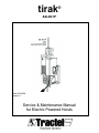
tirak
®
XE301P
Date: 06/28/05
Version:1
Service & Maintenance Manual
for Electric Powered Hoists
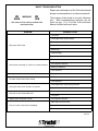
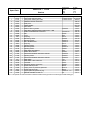
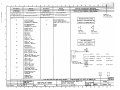
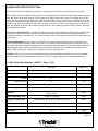
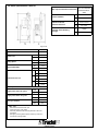
BASIC TROUBLESHOOTING
Repair and maintenance of the Tirak hoist should
always be accomplished in a safe environment!
WARNING
The purpose of this sheet is for quick reference
only. Most troubleshooting solutions can be
found on pgs. 17 & 18 of the Tirak Instruction
Manual included with each hoist.
This sheet is to be used by certified Tirak
technicians only!
PROBLEM
POSSIBLE CAUSE
Low power
Centrifugal switch (stuck closed)
Start capacitor defective
High amps and/or heat
Stator burned
Brake drag
Water damage
Hoist overloaded
Brake rectifier defective
Run capacitor defective
Hoist frozen electrically (ie. Won't run in either direction
Brake coil defective
Fuse defective
Hoist goes up but not down
Blocstop has been activated
E-stop button has been activated
Up and/or Down button does nothing
Fuse defective
Centrifugal switch (stuck open) defective
Hoist goes down when up button is pressed
Capacitor (start and/or run) defective
Start capacitor defective
Hoist will not lift a suspended load
Low power
Slightly higher amps than normal
Run capacitor defective
Main relay coil short circuit
Fuse in control circuit blows immediately
Fuse defective
Thermal protector is burned
Table 001
2
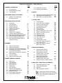
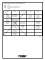
TABLE OF CONTENTS: TIRAK XE301P1
Page
Page
1) GENERAL INFORMATION
1-1
1-2
1-3
UL Listing Card
Model Identification Table
Test Certificate
5-12 Modification Comment
5-13 Assembly and Adjusting
4
5
6
6) MOTOR
2) SECONDARY BRAKE ATTACHMENT
2-1
BSO500 - Secondary Brake
Mounting Parts List
39
39
6-1
6-2
6-3
7
Replacement of Motor Winding (Stator) 40
Centrifugal Switch Replacement
42
Motor Parts List (E-3075 & E3076)
50
7) CONTROL BOX
3) WIRE ROPE DRIVING SYSTEM
3-1
3-2
3-3
3-4
3-5
3-6
3-7
3-8
3-9
3-10
3-11
3-12
3-13
Introduction
Tools Required
Blocstop Removal
External Inspection
Casing Cover Removal
Internal Inspection
Reassembly
Casing Cover Installation
Pressure System Replacement
Wire Rope Guide Band Replacement
Radial Packing Ring Replacement
Driver Disc Bearing Replacement
Wire Rope Drive System Parts List
(Drawing # 27610)
7-1
7-2
7-3
7-4
7-5
7-6
7-7
7-8
7-9
7-10
7-11
7-12
7-13
7-14
7-15
7-16
Tools Required
Control Box Cover Inspection
Ground (Cord/Plug) Check
Wiring Diagram Location
Stator/Winding Check
Fuse Check, F1
Thermal Protector
Relay Coil Resistance, K1, K2, K3
Brake Coil Resistance Check
Capacitor Checks
Centrifugal Switch
Pushbutton Check
Control Box Check
Power Check
Brake Rectifier Check
Control Box Parts List XE301P
Direct Control 110V
7-17 Control Box Parts List XE301P
Direct Control 220V
8
8
8
8
9
10
13
13
14
15
16
16
18
4) GEARBOX
4-1
4-2
4-3
4-4
4-5
4-6
4-7
Gearbox Disassembly
Gearbox Reassembly
Emergency Controlled Descent Brake
Disassembly and Check of Emergency
Controlled Descent Brake
Reassembly of Emergency Controlled
Descent Brake
Oil Level Gearbox
Gearbox Parts List (E-3205)
20
20
28
8-1
28
8-2
28
29
30
8-3
5) PRIMARY BRAKE FOR MOTOR
8-5
Brake Type
Tools Required
Brake Inspection
Brake Removal
Reassembly
Disc Inspection
Brake Air Gap Adjustment
Release Stirrup Replacement
Operational Check
Coil Resistance Inspection
Primary Brake Parts List
59
61
8) WIRING INFORMATION
8-4
5-1
5-2
5-3
5-4
5-5
5-6
5-7
5-8
5-9
5-10
5-11
52
52
52
53
53
54
54
55
55
55
57
57
57
58
58
32
32
32
34
35
36
36
37
38
38
38
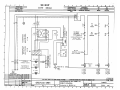
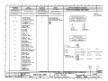
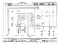
Wiring Diagram XE301P
Direct Control 110V, Plan
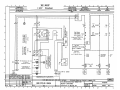
Wiring Diagram XE301P
Pendant Control, 110V Plan
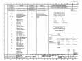
Wiring Diagram XE301P
Direct Control 220V, Plan
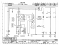
Wiring Diagram XE301P
Pendant Control, 220V Plan
Wiring Connection of Stator XE301P
63
65
67
69
71
9) WIRE ROPE / ADDITIONAL INFORMATION
9-1
9-2
9-3
9-4
Wire Rope Specification Tirak
Labels and Nameplates
Checklist
Hoist Specification XE301P
72
74
75
76
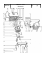
NOTE:
Throughout the text, parts will be referred to as
codes and positions (e.g stirrup bar, Code #47867,
Pos. 86). These codes and positions can be found at
the end of each chapter in the “Parts Lists” and
“Exploded Views”.
3
1) GENERAL INFORMATION
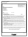
1-1 UL Listing Card
Northbrook, Ilinois (847) 272- 8800
Melville, New York (631) 271-6200
Santa Clara, California (408) 985-2400
Research Triangle Park,
North Carolina (919) 549-1400
Camas, Washington (360) 817-5500
TRACTEL INC
GRIPHOIST DIV
110 SHAWMUT RD
PO BOX 188
CANTON, MA 02021
TUFV
Equiptment, Scaffolding
April 18, 2002
TRACTEL INC GRIPHOIST DIV
110 SHAWMUT RD PO BOX 188, CANTON MA 02021
SA4785
Electric scaffold hoists, Models ETH-32L, XE301P, maximum load 700 lbs: Models ETH35C, ETH35C3,
ETH35X, LE500P, LE501P, TE401P, -401PA, XE500P, -501P, -501PA, maximum load 1000lbs; Models
TE1000P, -1001P, -1001PA, XE501PO, XE700P, -701P, XE720P, XE721P, maximum load 1500lbs; Models
TE1020P, -1021P, -1021PA, maximum load 2000 lbs; Model XE1020P, maximum load 2400 lbs; Model
XE2050P, maximum load 4400 lbs.
Manually operated scaffold hoists, Model TMS-600, maximum load 1320 lbs; Model TU-17, maximum
load 1500 lbs; Model TU-28, maximum load 3000 lbs; Model TU-32, maximum load 6000 lbs; Model 408, maximum load 880 lbs.
Pneumatic scaffold hoists, Models ATH32L, -32LB, XA300P, -300PB, maximum load 700 lbs; Models
ATH35C ATH35X, -35XB, LA500P, XA500P, -500PB, maximum load 1000 lbs; Models XA700P, -700PB,
XA720PB, maximum load 1500 lbs; Model XA1030PO, maximum load 1850 lbs; Model TA1020P, maximum load
2000 lbs; Model XA1020P, maximum load 2400 lbs; Model XA2050P, maximum load 4400 lbs; Model XA2650P,
maximum load 5300 lbs.
Independent secondary brakes, Model BS15.301, maximum load 1500 lbs; Model BS20.301, maximum
load 3000 lbs; Model BS35.30, maximum load 6000 lbs.
Modular work platform, “Modular Staging”, 2 to 12 m, rated 750 lbs; Models KD01, MP03, 2 to 18m, rated
750 to 1500 lbs; “PFD”, 2 to 15m, load 6000 lbs.
Work Cages, Model PMR0700D, PMR0701D, VSMV-PMR0710D, rated 1000 lbs; Model WC01, rated 400
lbs.
This equipment consists of separate parts inspected at the factory by Underwriters Laboratories Inc. and is
intended for use in complete complete installations. Installations are not inspected by Underwriters Laboratories
Inc. but should be made in accordance with requirements of authorities having jurisdiction.
LOOK FOR CLASSIFICATION MARK ON PRODUCT
Figure 101
4
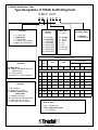
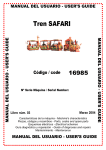
1-2 Model Identification Table
Type Designation of TIRAK Scaffolding Hoist
X SD 5 0 2 P
X E 3 01 P 1
Tirak-type
Wire Rope
in. [mm]
Capacity
lbs. [kg]
X = 1 driver disc
L = lightweight
T = 2 driver discs
G = Gripwinch (for material
handling only, US-version)
0
1
2
3
4
5
6
3 = 700 [300]
5 = 1000 [500]
7 = 1500 [700]
8 = 1600 [800]
10 = 2200 [1000]
16 = 3500 [1600]
20 = 4400 [2000]
30 = 6600 [3000]
=
=
=
=
=
=
=
Secondary Brake
1 = BSO500
2 = BS/BSO500
5/16 [8]
1/4 [6]
3/8 [9]
[10]
[11]
9/16 [14]
5/8 [16]
Working Speed f/m [m/min]
Kind of
Motor
Execution
P = Man riding
PA = 220 V, 1 Ph, 60 Hz, 500 kg for
USA/CAN only
PO = with overload
No declaration = material handling
Operation
A = Air operated
D = Dual wire rope Tirak
E = Electric operated Tirak
USA/Canada
H = Hydraulic operated
HB = Hydraulic operated with brake
N = Hand crank on motorshift
S = Silo hand crank on gear box
0=
3 Ph
50Hz
for X2000/3000
60Hz
50Hz
30
[9]
35
[11]
20
60Hz
[6]
23
[7]
[12]
45
[14]
or Air motor or Hydraulic motor
2=
3 Ph
60
[18]
70
3=
3 Ph
30/60
4=
3 Ph
15
5=
3 Ph
15/30 [4, 5/9] 17/35 [5, 5/11] 10/20
6=
3 Ph
15/60 [4, 5/18] 17/70 [5. 5/22] 10/40 [3/12] 12/45 [3, 5/14]
7=
3 Ph
variable speed, 0 to 35/70/100 [0 to 9/18/30]
1=
1 Ph
15
[9]
35
[11]
-
9=
G
39
[12]
39
[12]
-
[9/18] 35/70
[4, 5]
17
Kind of motor
3 Ph = 3 phase motor
1 Ph = single phase motor
G = DC motor
5
[22]
50
[11/22] 20/40 [6/12] 23/45
[5, 5]
10
[3]
12
[3/6] 12/23
-
-
[7/14]
[3, 5]
[3, 5/7]
-
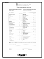
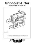
1-3 Test Certifacte XE301P
Figure 103
6
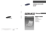
2) SECONDARY BRAKE ATTACHMENT XE301P
2-1 BSO500 Secondary Brake Mounting Parts List
#
1
2
3
4
5
6
7
Code
45735
9816
46847
67015
61645
20676
46496
Qty
1
4
1
1
1
2
4
Description
Blocstop Pin
Blocstop Washer
Mounting Strap A
Mounting Strap B
Casing Pin
Casing Washer
Cotter Pin
Dimensions / Comments
12 x 68 mm
Ø 12 / Ø 19 x 1 mm (Qty. as needed)
163.5 mm w/lug (no bend)
163.5 mm
10 x 66 mm
Ø 10 / Ø 16 x 1 mm (Qty. as needed)
4 x 25 mm
Table 201
Figure 201
7
3) WIRE ROPE DRIVING SYSTEM XE301P
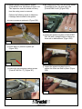
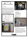
3-1 Introduction
NOTE
Regular Inspection services will decrease
downtime.
Although the drive system of the Tirak hoist is
one of the most simple and reliable system in the
market, it still requires service from an authorized
repair station for safe and efficient operation. It is
recommended the following service procedures
are performed every six (6) months but they may
need to be repeated more often depending on the
work environment the hoist is subjected to.
Figure 302
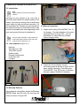
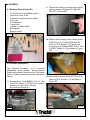
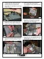
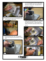
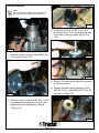
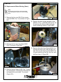
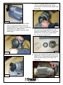
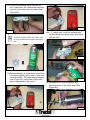
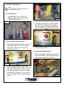
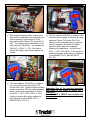
3-4 External Inspection
1) Inspect outer casing {Code #63695, Pos. 2}
for damage. Pay extra attention to the area
indicated shown in Figure 303. Look for
deformation or marks that may indicate
further damage inside.
NOTE
Parts and codes referred to in this section are
found on the spare parts list at the end of the
chapter (E-27610, Section 3-13).
3-2 Tools Required (Figure 301)
-
Hammer
Screwdriver (2, flat)
10mm Box wrench
Rubber mallet
Diagonal cutting pliers
5 mm Allen key
Pry Bars
Figure 303
2) Inspect the stirrup adapter and the
surrounding area as shown in Figure 304 for
wear, cracks or damage. If the stirrup bar
{Code #47867, Pos. 86} is bent, it indicates
improper rigging. Replace if necessary.
Figure 301
3-3 Blocstop Removal
Using diagonal cutting pliers, detach the Blocstop
BSO500 strap from the hoist by removing the
cotter pin shown in Figure 302.
Figure 304
8
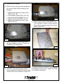
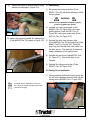
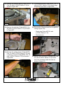
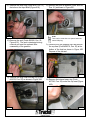
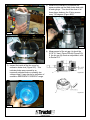
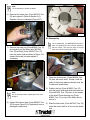
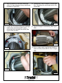
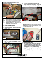
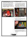
3-5 Casing Cover Removal
1) Remove the four (5) cap screw assemblies in
the corners (Figure 305) consisting of the
following:
a. M6x50 socket head cap screws {Code
#12016, Pos. 31}
b. Lock-washers {Code #16616, Pos. 32}
c. Flat washers {Code #36306, Pos. 71}
d. Square nuts {Code #39356, Pos. 33}
e. M6x16 socket head cap screw {Code
#5336, Pos. 52}
Figure 302
4) Inspect inside of cover {Code #63695, Pos.
2} for damage or evidence of wire rope jams
(Figure 308) and cracking near the stirrup bar
pocket (Figure 309).
Figure 305
2) Insert a screwdriver in the casing above
the stirrup adapter as shown in Figure 306.
Carefully pry the casing open.
Figure 308
Figure 309
Figure 306
All surfaces should be smooth to prevent cutting
or snagging of the wire rope. Replace the cover
if it is cracked or distorted.
3) When the cover opens enough, insert a
second screwdriver. Begin to lift evenly at the
corners of the cover as shown in Figure 307.
9
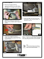
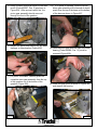
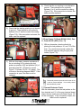
3-6 Internal Inspection
1) Remove and inspect the stirrup
adapter{Code #47867, Pos. 86} in Figure
310. Ensure it is straight and the anchor pin
is secure.
Figure 313
Figure 310
2) Remove and inspect the exit tube {Code
#63725, Pos. 41} shown in Figure 311.
Ensure it's free of debris inside. Replace as
needed.
Figure 311
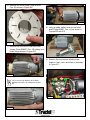
4) Inspect the upper wire rope guiding plate
{Code #63715, Pos. 46} and compare it to
Figures 314 and 315.
Figure 314
3) Remove the two socket head cap
screws {Code #8926, Pos. 53} and two
locking washers {Code #16616, Pos. 32} in
Figure 312 & 313.
Figure 315
Figure 315 shows how the guiding plate should
look like. Figure 314 shows a bent or damaged
wire rope guiding plate which must be replaced.
NOTE
IF the plate shows damage, this indicates a
wire rope jam has occurred and the pressure
system must be carefully inspected.
Figure 312
10
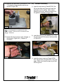
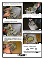
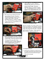
5) Remove the entrance tube {Code #40365,
Pos. 49} and snap ring {Code #6846,
Pos.57} as shown in Figure 320. Inspect the
entrance tube and snap ring for damage.
Ensure the entrance tube is free of debris.
Clean or replace as necessary.
Figure 322
8) Inspect the wire rope guiding band {Code
#24187, Pos. 9} (Figure 323) for wear or
damage. Replace as necessary (See
Section 3-10).
Figure 320
6) Inspect the wire rope guiding device
{Code #63705, Pos. 47} in Figure 321.
Replace as necessary.
Figure 323
9) Remove screw bushing located under wire
rope guiding device assembly (Figure 324).
Figure 321
7) Inspect the lower wire rope guiding plate
{Code #40405, Pos. 48, Figure 322} for wear
or damage. Replace as necessary.
Figure 324
11
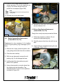
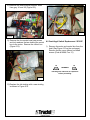
10) Inspect the two roller pressure system
{Code #23257 Pos. 80} shown in Figure 316.
This inspection must be carried out every
time the casing cover is removed.
d) Be careful not to lose the two spring wahers
{Code#16616 Pos. 32} and nyloc nuts
{Code #7996 Pos.81}.(Figure 328).
Perform the following check to determine
if damage has occurred to the system:
a) remove pressure system pin (Figure 325).
Figure 328
e) Inspect the pressure system {Code #23257
Pos. 80} with a straight edge to make sure
there are no deformations. (Figure 329).
Figure 325
b) check taper on pressure system pin
(Figure 326).
Figure 329
Figure 326
f) Inspect the pressure system’s pin to
ensure the rollers are held in place. (Figure
330).
c) remove the two pressure system screws
{Code #7146 Pos. 77} (Figure 327).
Figure 330
Figure 327
12
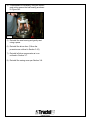
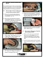
g)
Inspect the rollers to ensure they roll freely
and are not damaged. (Figure 331).
3-7 Reassembly
1) Re-grease the pressure system {Code
#23257, Pos. 80} with wheel bearing or white
lithium grease.
WARNING
DO NOT use molybdenum disulphide (moly-b)
grease or graphite type grease!
2) Reinstall the lower guide plate {Code
#40405, Pos. 48, Figure 322}, wire rope
guiding device {Code #63705, Pos. 47,
Figure 321} and upper guide plate {Code
#63715, Pos. 46, Figure 312}.
Figure 331
11) Inspect the carryimg handle for damage and
{Code #40335 Pos. 34} shown in Figure 332.
3) Reinstall the wire rope entrance tube
{Code #40365, Pos. 49} and snap ring {Code
#6846, Pos.57} in Figure 320. Place the
snap ring onto the entrance tube rotate it so
the tabs are up. This extra bit of clearance
eases installation of the casing cover.
4) Reinstall the exit tube {Code #63725, Pos.
41, Figure 311}. Ensure the tube is not
blocked.
5) Reinstall the stirrup anchor bar {Code
#47867, Pos. 86, Figure 310}.
Figure 332
3-8 Casing Cover Installation
1) Using a hammer and dowel punch, gently tap
the roll pins (clamping sleeves) flush into the
casing cover (#63695, Pos. 2, Figure 333).
NOTE
The regular service inspection is now complete. Clean all components with mineral spirits and dry thoroughly.
Figure 333
13
2) Carefully place the casing cover over the
pressure system dowel pin. Ensure it sits
directly over the pin!!! (Figure 334).
7) Load test the hoist and check the Blocstop
functions properly.
NOTE
General service of the wire rope drive system is
now complete. If during the general service
damage was discovered proceed as follows.
WARNING
It is prohibited to attempt repair
of the pressure system.
3-9 Pressure System Replacement
{Code #23257, Pos. 80}
Figure 334
3) Place one hand on the casing cover. Using a
dead blow RUBBER mallet, tap the cover
onto the base as shown in Figure 335.
NOTE
Keep pressure on the cover to prevent damage
to the cover.
If damage has occurred to the pressure system
by a rope jam (see Section 3-6, Step 4), the
pressure system must be replaced.
1) Carefully remove the pressure system dowel
pin by lifting it straight out its position. Be
sure not to damage the pin. If damage does
occur, gently remove any burrs with emery
cloth.
2) Lift the pressure system from the casing
base. Replace the unit.
3) After removal of the old system replace it with
a new unit {Code #23257, Pos. 80}.
5) Install the pressure system dowel pin into the
casing base first.
Figure 335
4) Using a hammer and dowel pin, realign the
roll pins flush with the base.
6) Grease the pressure system with wheel
bearing grease or white lithium grease.
WARNING
5) Reinstall the M6 casing cover
screws, washers and square nuts (See
Figure 305).
DO NOT use molybdenum disulphide (moly-b)
grease or graphite type grease!
6) Reinstall the Blocstop straps and Blocstop.
CAUTION
Ensure that the cotter pins are bent completely over
to prevent any sharp edges.
14
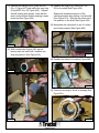
3-10 Wire Rope Guide Band Replacement
{Code #24187, Pos. 9}
Though replacement is rare, it may be necessary
if damaged beyond repair. This procedure
requires that the drive sheave is removed.
1) Remove the oil drain plug as shown in Figure
336. Ensure that gearbox is lying with the oil
plug to the high side to prevent excessive oil
loss. This will allow air pressure to neutralize
in the gearbox.
5) Remove the damaged wear band. Inspect
and repair the casing base retaining lip as
needed. Place a light coat of grease on the
back of the new wear band.
6) Install the new wear band. Make sure the
band sits firmly into the casing base recess
as shown in Figure 338.
2) Reinstall the oil plug. Do not apply too much
torque.
NOTE
You will be removing the oil plug again.
Figure 338
7) Using vise grips, twist the band into the
recess (Figure 339).
Figure 336
3) Turn the gearbox over so the driver disc
{Code #22357, Pos. 4} is face up. Use a
block of wood to level the gearbox. Remove
the wire rope guiding device (see Section 36, step 6).
4) Carefully with two pry bars remove the
driver disc as shown in Figure 337.
Figure 339
8) Reinstall the driver disc to the gearbox. There
will be resistance due to the air trapped
below the disc.
9) While holding the sheave in place, turn the
hoist over so that the oil plug is to the high
side again. Remove the oil plug same as
before.
Figure 337
15
10) Press or use a rubber mallet to push the
sheave into place. The air will expel from the
oil plug. The sheave should move into
position as air escapes (Figure 340).
NOTE
DO NOT stand in front of the oil plug hole as
oil may spray.
11) Reinstall the oil plug and tighten.
Figure 341
6) Reinstall the driver disc and remove excess
air as in Section 3-10.
3-12 Driver Disc Bearing Replacement
{Code #23836, Pos. 35}
Though this is rarely required proceed as follows.
Figure 340
3-11
1) Follow the procedure as above. Do not
remove the radial packing ring.
Radial Packing Ring Replacement
{Code #39516, Pos. 10}
Replacement is only necessary if oil is leaking
and the original packing ring is damaged (cut or
bent).
2) Carefully remove the driver disc with two pry
bars.
3) Inspect both top and bottom bearing for wear
or damage (Figure 342).
1) Remove the oil plug, pressure system, wire
rope guiding device and driver disc as above.
2) Clean the area carefully.
3) With two pry bars gently remove the old
packing ring. Do not damage the base.
4) Lightly grease the new packing ring and
place it in its position.
5) Using a brass punch or wooden dowel, tap
the packing ring into its position. Tap
alternately at the 12-6-9-3 o'clock positions
as shown in Figure 341.
Figure 342
16
4) If replacement is necessary, using the correct
gear puller remove the bad bearing as shown
in Figure 343.
Figure 343
5) Reinstall the new bearing and gently seat
using a press.
6) Reinstall the driver disc. (Follow the
procedure as outlined in Section 3-10)
7) Reinstall all drive components as in an
outlined in Section 3-7.
8) Reinstall the casing cover per Section 3-8.
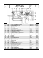
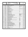
17
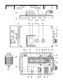
XE301P - 110V
Spare Parts
Position
-2
4
9
10
16
23
24
27
28
31
32
33
34
35
36
39
41
42
46
47
48
49
51
52
53
57
68
69
70
71
72
77
79
80
81
83
85
86
87
87.1
87.2
87.3
87.4
87.5
100
100.1
102
Wire rope drive
Part #
22048
63695
22357
24187
39516
40996
39306
39316
41996
39346
12016
16616
39356
40335
23836
39366
39376
63725
16286
63715
63705
40405
40365
4186
5336
8926
6846
37646
4176
37656
36306
41006
7146
16236
23257
7996
Qty.
1
1
1
1
1
1
1
1
1
1
4
9
4
1
1
5
1
1
1
1
1
1
1
2
1
2
1
1
1
1
4+1
1
2
4
1
1
22760
47867
42487
66145
61645
45735
9816
46496
41747
42707
14347
1
1
1
2
1
1
6
4
1
1
1
Description
Wire rope drive complete X300
CASING COVER X300
DRIVER DISC FOR WIRE ROPE DIA.8 MM
WIRE ROPE GUIDING BAND,COMPLETE F. 8 MM
RADIAL PACKING RING 160/180/10
BALL BEARING 6201
SHAFT SEAL 25/52/7
KEY A 5X5X45 DIN 6885
O-RING FOR MOTOR SIZE 80 120 X 2,5
CENTRIFUGAL BRAKE 1500 U/MIN
SOCKET HEAD CAP SCREW M 6X50 DIN 912
SPRING WASHER A6 DIN 127
SQUARE NUT M6 DIN 557
CARRYING HANDLE
Ball bearing 6201-2RS1
ROLL PIN 8 X 30 DIN 7346
CUP SEAL
Wire rope exit tube X300
ROLL PIN 8 X 12 DIN 7346
UPPER WIRE ROPE GUIDING PLATE
WIRE ROPE GUIDING DEVICE F. 8 MM
LOWER WIRE ROPE GUIDING PLATE
WIRE ROPE ENTRY TUBE
Socket head cap screw
Socket head cap screw
SOCKET HEAD CAP SCREW M 6 X 40 DIN 912
Retaining washer
Oil plug screw for petroleum gearboxes
Socket head cap screw
Copper gasket for gearbox oil plug
WASHER A 6,5X14X1,6 DIN 6902
SOCKET HEAD CAP SCREW M6X10 DIN 7984
SOCKET HEAD CAP SCREW M 6 X 25 DIN 912
RIVET 2 X 6 DIN 1476
PRESSURE SYSTEM COMPLETE
Nyloc nut
included with pos. 86 (one piece design)
Tirak nameplate
Tirak stirrup adapter
Brake coil assembly
BS/BSO Pin
Tirak pin
Blocstop pin
WASHER 13 X 19 X 1 DIN 988
COTTER PIN 4 X 25 DIN 94
Casing base without gears X300
Casing base with gears X300
Control descent pin with lanyard
Drawing No
Edition
Date
Page
Specifications
700#, 8mm
8mm
160x180x10
12x32x10
25x52x7
5x5x45
120x2.5
1900 rpm
M6x50
A6
M6
12x32x10
8x30
32x9.5
X300 S/N > 5336
8x12
X300 S/N > 5336
X300 S/N > 5336
M6x16
M6x30
M6x40
M16x1.5
M6x20
16x22x1.5 - Cu
A6.5
M6x25
2x6
M6
Metal
FDB 13 / 96V
10x72
10x66
12x68
13x19x1
4x25
for motor size 80
for motor size 80
27610
US-1
1/05
1/2
List Price
$2,618.47
$204.39
$546.10
$25.44
$32.76
$7.27
$9.47
$0.39
$4.77
$137.16
$0.39
$0.13
$0.26
$23.14
$9.82
$0.61
$9.47
$0.00
$0.39
$10.97
$58.64
$6.66
$10.82
$0.00
$0.00
$0.26
$0.00
$3.76
$0.00
$0.39
$0.56
$0.46
$0.26
$0.13
$334.61
$0.15
$9.47
$86.98
$0.00
$10.82
$12.42
$7.12
$2.01
$0.26
$586.07
$1,917.80
$18.93
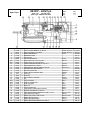
Spare Parts
XE301P - 110V
Wire rope drive
Drawing No
Edition
Date
Page
27610
US-1
1/05
2/2
4) GEARBOX
2) Remove the casing cover and internal drive
parts as shown in Figures 403, 404, 405,
406, 407, 408 and 409.
4-1 Required Tools (Figure 401)
-
17 mm wrench or adjustable wrench
Allen keys 8 mm, 5 mm
internal and external snap ring pliers
2 pry bars
2 screwdrivers
1 gear puller
1 plastic or rubber mallet
Brass punch
Rags or towels
Figure 403
Figure 401
2a) Remove all the casing cover screws {Code
#12016 Pos. 31, & Code #5336 Pos. 52
refer to 27610, Section 3-13} and pry off
the casing cover {Code #63695, Pos. 2, refer
to 27610, Section 3-13} as shown in Figure
404.
4-2 Gearbox Disassemby
The following procedure is for complete
disassembly of the gearbox. We recommend
that the procedure be carried out by a Tirak repair
facility. If repair is essential at the site proceed as
follows:
1) Remove the 4 {Code #26097, Pos. 12, refer
to E-3075, Section 3-13} M5x10 mm screws
as shown in Figure 402. Remove
the motor per Section 6-1.
Figure 404
2b) Remove the exit tube {Code #63725, Pos. 41,
refer to 27610, Section 3-13} as shown in
Figure 405.
Figure 405
Figure 402
20
2c) Remove the pressure spring {Code #23257,
Pos. 80, refer to 27610, Section 3-13} as
shown in Figure 406.
2f) Pry off the driver disc {Code #22357, Pos. 4,
refer to 27610, Section 3-13} using 2 large
screwdrivers as shown in Figure 409.
Figure 406
Figure 409
2d) Remove the inlet tube {Code #40365, Pos.
49, refer to 27610, Section 3-13} as shown
in Figure 407.
2g) Remove the following items from the gearbox
casing (Figure 410):
- Plastic plug {Code #67746, refer
to 27610, Section 3-13}
- Wearband pins
Figure 407
2e) Remove the guiding device {Code #63705,
Pos. 47, refer to 27610, Section 3-13} held
in place by 2 screws {Code #8926, Pos. 53,
refer to 27610, Section 3-13} as shown in
Figure 408.
Figure 410
2h) Remove the (4) roll pins {Code #39366, Pos.
36, refer to 27610, Section 3-13} should
they have remained inside the base as
shown in Figure 411.
Figure 408
Figure 411
21
3) Using a 10 mm hex, remove the oil plug
{Code #37646, Pos. 68} and drain the
synthetic gear oil into a clean bucket.
Inspect the oil for brass flakes or metal filings
(Figure 412).
6) Rotate the gearbox cover {Code #40505,
Pos. 3} slightly with a brass hammer
(or soft hammer) and tap upwards as shown
in Figure 415.
Figure 415
7) Carefully pry off the gearbox cover {Code
#40505, Pos. 3} as shown in Figure 416.
Avoid damaging the casing base.
Figure 412
4) Inspect the plug and copper gasket {Code
#37656, Pos. 70} for wear or damage as
shown in Figure 413. Replace if necessary.
Figure 416
Figure 413
8) Inspect the cover {Code #40505, Pos. 3} for
damage (Figure 417). Replace the ‘O’-ring
{Code #39286, Pos. 12}.
5) Remove the (4) M6x20 socket head screws
{Code #4176, Pos. 69} as shown in Figure
414.
Figure 417
Figure 414
22
12) Remove any and all spacers {Code #25136,
Pos. 21} as shown in Figure 421.
9) Remove the snap ring {Code #536, Pos 13}
that sits on the input shaft (Figure 418).
Figure 421
Figure 418
NOTE:
There may be more than one spacer below the
internal snap ring.
10) Remove the seal {Code #39306, Pos. 23,
Figure 419}. The seal is destroyed during
removal and must be replaced after
reassembly of the gearbox.
13) Carefully turn the gearbox over and remove
the cup seal {Code #39376, Pos. 39} at the
bottom of the hoist as shown in Figure 422.
Dispose of the old seal.
Figure 419
Figure 422
11) Remove the large internal snap ring {Code
#16576, Pos. 22} as shown in Figure 420.
14) Remove the internal snap ring {Code
#37796, Pos. 38} under the cup seal (Figure
423).
Figure 423
Figure 420
23
15) Using a rubber dead blow mallet, hit the shaft
pinion {Code #22367, Pos. 5} as shown in
Figure 424. After several careful hits, the
pinion gear assembly should come out
through the front of the gearbox.
17a) If no press is available, carefully tap the
worm gear assembly with a hammer or brass
punch from the top of the base out the bottom
of the base as shown in Figure 427.
Figure 424
Figure 427
16) Inspect the pinion and bearing for any wear,
damage, or discoloration (Figure 425).
18) Once the worm gear exits the base, the lower
bearing {Code #40996, Pos. 16} must be
removed (Figure 428).
Figure 425
17) If a press is available, carefully press the
complete worm gear assembly from the top
of the gearbox out of the bottom of the
gearbox (Figure 426).
Figure 428
19) Install the gear puller as shown in Figure 429
and remove the bearing.
Figure 426
Figure 429
24
20) Remove the steel worm {Code #22397, Pos.
7} through the large gearbox opening as
shown in Figure 430.
4-2)
Gearbox Reassembly
1) Install the top bearing {Code #37356, Pos.
20} on the steel worm gear and insert the
assembly into the casing. With a brass
hammer and punch, press the bearing into
the gearbox as shown in Figure 432.
Figure 430
NOTE:
The bearing MUST be replaced in the same
orientation. Failure to do so will cause the hoist
to malfunction.
Figure 432
2) Install the bearing {Code #40996, Pos. 16} on
the opposite end of the worm shaft as shown
in Figure 433.
21) Inspect the worm gear for wear, damage, or
discoloration (Figure 431). Replace if
necessary.
Figure 433
Figure 431
3) Install the lower snap ring {Code #37796,
Pos. 38} as shown in Figure 434 on the next
page. Make sure that the snap ring is fitted
into the groove.
25
6) With a press or punch, seat the large brass
gear {Code #22387, Pos. 6} into the gearbox
as shown in Figure 437. Be careful not to
damage worm wheel.
Figure 434
4) Install the lower cup seal {Code #39376, Pos.
39} as shown in Figure 435.
Figure 437
7) Install the spacer(s) {Code #25136, Pos. 21}
and snap ring {Code #16576, Pos. 22} above
the bearing as shown in Figures 438-440.
Make sure that the snap ring is fitted into the
groove.
Figure 435
Figure 438
5) Insert the large brass gear {Code #22387,
Pos. 6} into the gear case as shown in Figure
436.
Figure 439
Figure 436
Figure 440
26
8) Take the tool for inserting the top seal {Code
#39306, Pos. 23} and place the seal on the
tool as shown in Figure 441.
Figure 444
10) Tighten the 4 screws {Code #4186, Pos. 69}
and lockwashers {Code #16616, Pos. 72} as
shown in Figure 445.
Figure 441
8a) Hammer the seal {Code #39306, Pos. 23}
into place as shown in Figure 442.
Figure 445
11) Refill the gearbox with 1.4 liters of mineral
oil per specification.
Figure 442
9) Inspect the O-ring {Code #39286, Pos. 12}
and put the cover {Code #40505, Pos. 3} on
the gearbox opening as shown in Figure 443
and 444.
Figure 446
12) Replace all wire rope drive and motor
components. Load test the hoist.
WARNING
Once this procedure has been performed and the
complete Tirak reassembled, the Tirak must be load
tested to 125% of it’s rated capacity (875 lbs.).
Figure 443
27
4-3
Emergency Controlled Descent Brake
XE301P
The controlled descent brake is found between
the motor and gearbox. It is sealed and therefore
should be clean and not worn. It only functions
during intentional use for emergency descent.
4-4
Dissassembly an Checks of Emergency
Controlled Descent Brake XE301P
Figure 449
5) Examine the brake assembly. The shoes
should not be worn and the springs should be
correctly in place (See Figure 450). The
lining should be secure.
1) Remove the motor from the gearbox by
unscrewing the 4 M5x153 threaded bolts
{Code #26097, Pos. 12}.
2) Remove the centrifugal brake assembly
{Code #39346, Pos. 28}. If it is stuck, you
can thread in 2 M6 screws and use them to
pull out the brake (See Figure 447).
Figure 450
6) Check that the speed marked on the brake in
RPM corresponds to the motor nameplate
UPM. 1900 is normal.
4-5
Figure 447
3) Inspect the brake pocket. The ring should
show no wear. There should be no oil, dust,
or debris inside. Clean if necessary with
brake cleaner (See Figure 448).
Reassembly of Emergency Controlled
Descent Brake XE301P
1) Make sure the snap ring is on the shaft.
Insert the key {Code #40986, Pos. 11}.
Grease the shaft lightly for ease of brake
removal for future inspections (See Figure
448).
2) Insert the brake assembly with the threaded
holes upward (See Figure 451). Replace the
o-ring.
Figure 448
4) Remove the O-ring seal {Code #41996, Pos.
27}. Inspect it for damage and replace if
flattened or damaged (Figure 449).
28
Figure 451
3) Refit the motor to the gearbox.
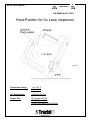
4-6 Oil Level Gearbox
WARNING
USE MINERAL OIL ONLY!
Hoist-Position for Oil Level Inspection
Figure 452
Temperature Range:
14 to 122 °F
-10 to +50 °C
API Specification:
SAE85W-140 GL5
Sample Oils:
BP Hypogear EP 90
SHELL Spirax HD 90
TEXACO Multigear EP6 S80 W90
29
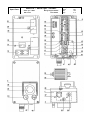
XE301P - 110V
Spare Parts
Position
-1
3
5
6
7
8
9
10
11
12
13
14
15
16
18
19
20
21
22
23
301)
30.11)
30.21)
37
38
39
45
51
68
69
70
72
Part #
42707
41747
40505
22367
22387
22397
40305
24187
39516
40986
39286
536
25406
42016
40996
9996
39296
37356
25136
16576
39306
41066
41046
41056
576
37796
39376
21940
4176
37646
4186
37656
16616
Gearbox
Qty.
1
1
1
1
1
1
1
1
1
1
1
1
1
1
1
1
1
1
1
1
1
2
1
2
1
1
1
1.4
2
1
4
1
4
Description
Casing base with gears X300
Casing base without gears X300
GEARBOX COVER X300/L500
Shaft pinion
WORM WHEEL
Worm shaft
Distance tube for gearbox
WIRE ROPE GUIDING BAND,COMPLETE F. 8 MM
RADIAL PACKING RING 160/180/10
KEY
O-ring
Snap ring
Ball bearing 16004
Ball bearing 6304
BALL BEARING 6201
Snap ring
Adjusting washer
Ball bearing 6205
Adjusting washer
SNAP RING 52X2 DIN472
SHAFT SEAL 25/52/7
ADJUSTING WASHER 20X28X0.5 DIN 988
Adjusting washer
ADJUSTING WASHER 20X28X0.2 DIN 988
SNAP RING
SNAP RING J 32X1.2 DIN 472
CUP SEAL
Petroleum gearbox oil (per liter)
Socket head cap screw
Oil plug screw for petroleum gearboxes
Socket head cap screw
Copper gasket for gearbox oil plug
SPRING WASHER A6 DIN 127
Drawing No
Edition
Date
Page
E-3205
US-1
1/05
2/2
Specifications
for motor size 80
for motor size 80
21x30x66
160x180x10
6x6x22
88x3
20x1.2
20x42x8
20x52x15
12x32x10
25x1.2
25x35x1
25x52x15
42x52x1
52x2
25x52x7
20x28x0.5
20x28x0.1
20x28x0.2
12x1
32x1.2
32x9.5
80/90W
M6x20
M16x1.5
M6x16
16x22x1.5 - Cu
A6
1) To compensate for eventual clearance between distance tube (8) and/or worm wheel (6) and ball bearing (14)
List Price
$1,917.80
$586.07
$63.00
$0.00
$167.00
$0.00
$0.00
$25.44
$32.76
$0.35
$0.00
$0.00
$15.88
$13.87
$7.27
$0.39
$0.00
$0.00
$0.00
$1.38
$9.47
$0.11
$0.00
$0.11
$0.11
$0.18
$9.47
$0.00
$0.00
$3.76
$0.00
$0.39
$0.13
Spare Parts
XE301P - 110V
Gearbox
Drawing No
Edition
Date
Page
E-3205
US-1
1/05
2/2
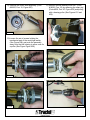
5) PRIMARY BRAKE FOR MOTOR
WARNING
Upon completion of any brake maintenance, it is
mandatory that a load test of the hoist be completed!
5.1 Brake Type
All Tirak XE301P hoists are fitted with the
adjustable Precima type brake. This section
covers the service and repair of this brake only.
The XE301P has a 96V or 190V DC brake. Prior
to maintenance, verify the brake voltage. This
voltage is stamped on the brake nameplate,
located on the wiring diagram (Figure 501), on
the fan cover (Figure 502), and is stamped on the
top of Precima brakes (Figure 503).
Figure 503
5.2 Tools Required (Figure 504)
-
5 mm Allen key
Snap-ring pliers
10 mm crescent wrench
8 mm crescent wrench
2 Flat screwdrivers
Silicone (RTV) sealant
Tape
Calipers (micrometer)
Feeler gauges
Figure 501
Figure 504
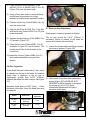
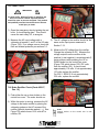
5.3 Brake Inspection
1) Unscrew the 4 screw {Code #16086, Pos 31}
and washer assemblies using an 8mm
crescent wrench. Remove the fan cover
{Code #26607, Pos. 8} as shown in Figure
505 on the next page. If crushed, replace
and ensure that the fan spins unobstructed
(Figure 506 on the next page).
Figure 502
32
3) Measure the clearance (a) between the
pressure plate and the black brake body with
a feeler gauge. This should be done in all
three places between the 3 fixing screws
every 120 degrees (Figure 508).
Figure 505
Figure 508
4) Measurement of the air gap (a) should be
0.012"(0. 3mm) (Figure 509 and Figure 510).
If the air gap (a) needs an adjustment, refer
to Section 5.6.
Figure 506
2) Inspect the inside of the fan cover for
excessive brake dust (Figure 507). This
indicates brake wear caused by an
incorrectly adjusted brake or possibly low
voltage usage. It may also be an indication of
excessive EMERGENCY DESCENT usage.
Figure 509
Figure 510
Figure 507
33
5.4 Brake Removal
NOTE:
Prior to removal, pay attention to the brake orientation and mark it for realignment (Figure 511).
Figure 513
3) If the fan key {Code #16256, Pos. 23} is
removable, do so. If not, just wrap some tape
around the keyway for safety (Figure 514,
515).
Figure 511
1) Remove the fan snap ring {Code #3866, Pos.
21} shown in Figure 512.
Figure 514
Figure 515
4) Remove the three socket head fixing screws
w/ locking washers.
5) Remove the whole brake assembly {Code
#49746 (110 V), or #47406 (220 V) Pos. 35}
as shown in Figure 516.
Figure 512
2) Remove the fan {Code #16186, Pos. 7} with
two screwdrivers placed under the fan and
against the motor shaft and pry upward
(Figure 513).
Figure 516
34
NOTE:
It is not necessary to unwire the brake.
6) Remove the brake rotor {Code #47416, Pos.
38} and inspect it (Refer to Section 5-6).
Replace if worn or damaged (Figure 517).
Figure 519
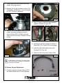
5.5 Reassembly
Figure 517
7) Remove the snap ring {Code #3866, Pos. 21}
and carefully pry the brake hub {#47426,
Pos. 39} and key {Code #16256, Pos. 23}
from the motor shaft as shown in Figure 518.
Inspect the brake hub and replace if
necessary.
NOTE:
Prior to reassembly, it is MANDATORY that the 3
brake end shield holes have silicone applied to
seal the screws. This must be done to prevent
water entry into the motor (Figure 520).
Figure 520
1) Place the friction plate {Code #62026, Pos.
36} over the motor shaft. Rotate it until the
holes of the friction plate are directly over the
3 brake end shield holes.
Figure 518
2) Position the key {Code #16256, Pos. 23}
onto the motor shaft and slide the brake hub
{Code #47426, Pos. 39} down to the bottom
of the shaft. Place the snap ring {Code
#3866, Pos. 21} on top of the brake hub to
secure it.
NOTE:
Care must be taken when replacing the hub not to
damage it.
8) Inspect the friction plate {Code #62026, Pos.
36} for wear (Figure 519). Replace all worn or
damaged components.
35
3) Slide the brake disc {Code #47416, Pos. 38}
down the motor shaft so it fits over the brake
hub.
4) Place the whole brake assembly {Code
#49746 (110 V), or #47406 (220 V) Pos. 35}
(Figure 516) over the motor shaft.
5) Using a 5mm allen wrench, screw the three
socket head fixing screws w/ locking
washers to hold the brake assembly in place.
6) Postition the fan key {Code #16256, Pos. 23}
onto the motor shaft.
Figure 521
7) Align the fan {Code # 16186, Pos. 7} key hole
with the fan key {Code #16256, Pos. 23} and
press downward.
5-7 Brake Air Gap Adjustment
8) Replace the fan snap ring {Code #3866, Pos.
21} shown in Figure 512.
The air gap should be 0.012" [0.3mm]. If
necessary, adjust by means of the three set
screws and counter nuts as follows:
9) Place the fan cover {Code #68287, Pos. 6}
as shown in Figure 511 over the brake. The
handle should face in the direction of the
control box.
1) Loosen the three socket head fixing screws a
few turns as shown in Figure 522.
If adjustment is required proceed as follows.
10) Install the 4 screw {Code #16086, Pos 31}
and washer assemblies using an 8mm
wrench.
5-6 Disc Inspection
A new brake disc has a thickness of 5 mm, which
is indicated on the top of the brake. If excessive
brake wear is apparent or the air gap is
significantly greater than 0.012" (0.3mm),
measure the brake disc with a caliper. See Figure
521.
Maximum brake wear is 0.040" [1mm] - If disc
thickness is less than 4 mm, the brake disc must
be replaced.
Model
Brake Size
New Disc
Thickness
XE 301P 110V
FDB 10 / 96V
(#49746)
5 mm
XE 301P 220V
FDB 10 / 190V
(#47406)
5 mm
Figure 522
2) Adjust each of the three 8mm adjustment
screws (Figure 523) AN EQUAL # OF
DEGREES to either increase or decrease
the air gap (a) to 0.012" [0.3mm].
Unbalanced adjustments will lead to
excessive brake wear.
Figure 523
36
3) Tighten down the three socket head fixing
screws w/locking washers.
4) Measure the air gap as shown in Figure 524.
If necessary, repeat steps 1-3 until an air gap
of 0.012" (0.3mm) is achieved.
Figure 526
2) Use a C-clamp to hold the brake assembly
together as shown in Figure 527.
Figure 524
5) Remove each of the three socket head fixing
screws separately and apply a bead of
silicone (Figure 525) to the tip to prevent
water entry into the motor. Replace all three
screws.
Figure 527
Figure 528
3) Unscrew the two fixing screws as shown in
Figure 528 (“E” in Figure 530 on next page).
4) Install the new brake release stirrup (B)
{Code #61716, Pos. 40}.
5) Install the new fixing screws (Figure 529).
Figure 525
Figure 529
NOTE:
The adjustment of the gap on the brake release
stirrup has NOTHING TO DO with the adjustment
of the air gap of the brake!
5-8 Release Strirrup Replacement
1) Carefully remove all sealant (Figure 526) if
the brake release stirrup is to be replaced.
37
6) Install the brake onto the motor. Apply
silicone to the brake end shield holes prior
to installation to prevent water from entering
the motor. Replace all three screws.
4) If there is any heat being generated, reinspect the brake air gap because the disc is
most likely dragging.
5) If no heat is generated, reinstall the fan
cover. When installing the fan cover, pull
back as shown in Figure 532 to gain more
clearance for the emergency descent lever.
Figure 530
7) Measure distance (b) between the brake
retraction plate (C) and washer (D) in Figure
530. This distance must be 0.039" (1mm). If
necessary, adjust symmetrically on both
sides by means of the two screws (E).
Figure 532
5-9 Operational Check
Testing must be carried out once the brake has
been completely reassembled. With the fan cover
removed, proceed with the operational check:
1) With the correct power supplied to the hoist,
push the up or down button.
2) Visually inspect that the anchor disc (“C” in
Figure 530) lifts evenly upward away from the
brake disc. A pronounced "click" or "snap"
should be heard when it retracts
magnetically.
5-10 Coil Resistance Inspection
Measure the resistance of the brake coil as
shown in the Electrical Control Box chapter.
XE301P brake resistances listed in table 501.
Brake coil resistance is also found on the wiring
diagram.
WARNING
3) CAREFULLY feel for heat (Figure 531)
around the entire electromagnetic brake
being cautious around the rotating fan.
Upon completion of any brake maintenance, it is
MANDATORY that a load test of the hoist be
completed.
5-11 Parts List Primary Brake
Figure 531
Brake Type
Code
Complete
Disc
Code
Release
Code
Hub
Code
110 V Precima Model
FDB10 Resistance
332 Ohms
49746
47416
61716
47416
220 V Precima Model
FDB10 Resistance
1430 Ohms
47406
47416
61716
47416
Table 501
38
5-12 Modification Comment
Subject : Adjusting of the brake release lever.
Reason : Simplify assembly and inspection
The former instructions regarding the adjustment
of the distance “b” (Figure 530) for the brake
release lever “B” in (Figure 530) “with the brake
opened” were based on an internal production
instructions of the manufacturer by means of a
special tool.
After discussion with the manufacturer the
procedure can be simplified by checking the
distance “b” (Figure 530) “with the brake closed”;
in consequence the manufacturer’s value of
0.039” [1mm] must be reduced by the air gap (a)
0.012” [0.3mm], which gives the new checking
dimension of 0.028” [0.7mm].
5-13 Assembly and Adjusting
Fix the new brake to the motor and connect it into
the control box.
Check the air gap (a) = 0.012” [0.3mm] around
the brake with a feeler gauge - if necessary,
adjust by means of set screws “A” (See Section
5-3).
When assembling a new brake check adjustment
of brake release lever “B” (See Section 5-7).
With the brake closed the distance (b) between
anchor disk “C” and washers “D” must be 0.028”
[0.7mm]. If necessary, adjust symmetrically on
both sides by means of screws “E”.
WARNING
The adjustment of the brake release lever must not
be changed afterwards, even in case of an air gap (a)
readjustment, as security is adversely affected.
39
Figure 530
6) MOTOR
6-1 Replacement of Motor Winding (Stator)
NOTE:
The motor and control box must be removed
before attempting to replace the motor winding
(stator).
1) Remove the fan cover M5x10 hex screws
{Code #16086, Pos. 31} as shown in Figure
601.
Figure 603
4) Remove the whole brake assembly {Code
#49746 (110 V), or #47406 (220 V) Pos. 35}
by removing the three socket head fixing
screws w/locking washers. (Figure 604).
Figure 601
2) Remove the fan snap ring {Code #3866,
Pos. 21} shown in Figure 602.
Figure 604
5) Remove the brake disc {Code #47416, Pos.
38} and the brake hub {Code #47426, Pos.
39}. Remove the snap ring {Code #536, Pos.
20} and carefully pry the hub from the motor
shaft as shown in Figure 605.
Figure 602
3) Remove the fan {Code #16186, Pos. 7} using
two screwdrivers. Placed them under the fan
and against the motor shaft. Pry upward.
(Figure 603).
40
Figure 605
6) Remove the friction plate {Code #62026,
Pos. 36} shown in Figure 606.
Figure 609
8) Using a rubber mallet, drive out the motor
shaft {Code #26587, Pos. 15} as shown in
Figures 609 and 610.
Figure 606
7) Remove the four M5x153 mm hex head
screws {Code #26097, Pos. 12} holding onto
brake flange shown in Figure 607.
Figure 610
9) Remove the ring terminal winding wires
(black-w, red-z, red-u and black-v) as shown
in Figure 611.
Figure 607
NOTE:
Prior to removal, pay attention to the brake
orientation and mark it for realignment (Figure
608).
Figure 611
Figure 608
41
10) Remove the small thermal protector wires
from grey X1 and X2 (Figure 612).
Figure 614
Figure 612
11) Remove the four socket head cap screws
and lock washers that are holding the control
box to the motor. Remove the control box
(Figure 613).
6-2 Centrifugal Switch Replacement XE301P
1) Remove the motor and control box from the
hoist (See Figure 615 on the next page).
Remove the fan cover 4x8mm hex head
screws {Code #16086, Pos. 31}.
WARNING
Discharge the start and run capacitors
before proceeding.
Figure 613
12) Replace the old winding with a new winding
as shown in Figure 614.
42
3) Take off the primary brake {Code #49746
(110 V), or #47406 (220 V) Pos. 35} by
removing the 3 socket head cap screws (See
Figure 618).
Figure 615
2) Remove the fan snap ring {Code # 3866,
Pos. 21, Figure 616} and pry off the fan
{Code #16186, Pos. 7} using 2 screwdrivers
(See Figure 617). Make sure the
screwdrivers are against the motor shaft
when prying.
Figure 618
4) Remove the brake disc {Code #47416, Pos.
38}, friction disc {Code #62026, Pos. 36},
snap ring {Code #3866, Pos. 21}, hub {Code
#47426, Pos. 39} and key {Code #16256,
Pos. 23} shown in Figure 619.
Figure 619
Figure 616
5) Remove the 4 M5X153 threaded bolts {Code
#26097, Pos. 12} that hold the cast aluminum
brake end bell housing to the motor (See
Figure 620).
Figure 617
Figure 620
43
6) Mark the position of the white centrifugal
switch for easy alignment during reassembly
as shown in Figure 621.
8) Unscrew the 3 M4x16 screws {Code #16996,
Pos. 30} holding the centrifugal switch (See
Figure 624).
Figure 624
Figure 621
9) Mark the flange for reassembly (See Figure
625).
7) Loosen the 2 screws holding the centrifugal
switch wires and remove the 2 spade
connectors from beneath the screws (See
Figures 622 and 623).
Figure 625
10) With a rubber mallet, tap the cast aluminum
brake end bell {Code #26107, Pos. 5, Figure
626}.
Figure 622
Figure 623
Figure 626
44
11) Remove the motor shaft assembly {Code
#26587, Pos. 15, Figure 627}.
13) Remove the ball bearing 6004-RS1 {Code
#16536, Pos. 18} by removing the snap ring
{Code #536, Pos. 20, Figure 630} and pulling
with a bearing puller (See Figures 631 and
632).
Figure 627
12) Loosen the set of screws holding the
mechanical part of the centrifugal switch
(See Figure 628) and push the assembly
away from the ball bearing to allow room for
a puller (See Figure Figure 629).
Figure 630
Figure 631
Figure 628
Figure 632
Figure 629
45
14) Remove the bearing. Notice that one side is
sealed and the other side is not (See Figure
633).
Figure 633
17) Remove the white centrifugal switch and
mechanical actuating mechanism (See
Figure 636 and 637).
Figure 636
15) Remove the snap ring {Code #536, Pos. 20}
in Figure 634.
Figure 637
NOTE
We suggest you layout the parts on the
workbench for ease of reassembly (See Figure
638).
Figure 634
16) Remove the bearing cover {Code #27935,
Pos. 6} in Figure 635.
Figure 638
Figure 635
46
18) Check the centrifugal switch contacts for
burn, malfunction, etc. Manipulate the switch
to see if the contacts open and close (See
Figure 639).
Figure 642
Figure 639
19a) If it stays open, clean the contacts with
contact cleaner and emery cloth (See Figure
643 and 644).
NOTE
Sometimes contact cleaner and emery cloth
can repair a malfunctioning switch (See Figure
640).
Figure 643
Figure 640
19) Before installation of a new switch, check that
it functions properly with a meter. Open and
close the switch. The meter should indicate
open (Figure 641) and closed (Figure 642)
when manipulated on the bench.
Figure 641
Figure 644
20) Reassemble the new mechanical and
electrical switch on the motor shaft (See
Figure 645).
Figure 645
47
21) Replace the bearing cover {Code #27935,
Pos. 6, Figure 637} and reaffix the snap ring
{Code #536, Pos. 20, Figure 636}. Repack
the ball bearing with grease. Note that the
seal is on the bottom and the bearing is open
to the top (See Figure 646).
23) Replace the snap ring {Code #536, Pos
20} on the shaft (See Figure 630).
Sqeeze the mechanical portion of the
centrifugal switch while sliding it up the shaft
(See Figure 651). With the set screw lock it
into position on the shaft (See Figure 628).
23) Manipulate the new switch to see if it opens
and closes properly (See Figure 649).
Figure 646
22) With a metal tube (Figure 647) tap the
bearing onto the shaft until it contacts the
snap ring below it (See Figure 618).
Figure 649
24) Reattach the wires to the switch (Figure 650).
Figure 647
Figure 650
25) Check the winding for burns or damage (See
Figure 651).
Figure 651
Figure 648
48
26) Put the cast aluminum brake end shield on
the motor shaft (See Figure 652).
Figure 652
27) Realign the switch and retighten the 3 M4x16
screws {Code #16996, Pos. 30, Figure 629}.
Place silicone around the bottom of the cast
aluminum end shield to seal the joint
between the winding and shield.
28) Place the motor shaft assembly into the
winding, align the marks and tighten the 4
M5x153 {Code #26097, Pos. 12} bolts.
29) Reassemble the brake per Section 5-12.
30) Replace the fan cover. Refit the motor and
test.
49
XE301P - 110V
Spare Parts
Position
1
5
6
7
8
(8a*)
(8b*)
10
12
14
15
18
19
20
21
22
23
(25*)
(26*)
(27*)
(28*)
30
31
33
35
36
37
38
39
40
Part #
15648
26597
26107
27935
16186
26607
47837
69536
41996
26097
15796
26587
16536
26376
536
3866
39316
16256
16206
16236
16706
3776
16996
16086
16246
49746
62026
62446
47416
47426
61716
110V / 1ph.
0.55 kW / 60Hz
Motor type: UBE 80/11-4F-100V
Qty.
1
1
1
1
1
1
1
1
1
4
1
1
1
1
2
3
1
2
1
2
1
2
3
4
8
1
1
1
1
1
1
Description
Motor complete UBE80/11-4F, XE301
Stator for UBE80/11-4F, XE301
BRAKE END SHIELD
BEARING COVER
Fan for Motor
FAN COVER XE301p
Replacement rain cover w/ handle
Plastic cap for fan cover with hole
O-RING FOR MOTOR SIZE 80 120 X 2,5
THREADED BOLT C/W NUT
CENTRIFUGAL SWITCH XE301P, LE501P
MOTOR SHAFT WITH ROTOR
Ball bearing 6004-RS1
SHAFT SEAL DIA.20/35/7 BASL
Snap ring
Snap ring
KEY A 5X5X45 DIN 6885
Key
Motor nameplate
RIVET 2 X 6 DIN 1476
Brake nameplate
Blind rivet
Cheese head screw
HEXAGONAL SCREW M5X10 DIN933
SPRING WASHER DIA.5 DIN 127
Electromagnetic brake complete
FRICTION PLATE FDB10
Brake coil assembly
BRAKE ROTOR FDB 10
BRAKE HUB SIZE FDB10
BRAKE RELEASE STIRRUP CPL. FDB 10
*) not shown
Drawing No
Edition
Date
Page
Specifications
0.55kW, 110V
0.55kW, 110V
Sz. 80
Sz. 80
Size 80
120x2.5
M5x153
2 pieces incl.
20x42x12
20x35x7
20x1.2
15x1
5x5x45
A5x5x16
Metal
2x6
Metal
2.4x6
M4x16
M5x10
A5
FDB 10 / 96V
FDB 10
FDB 10 / 96V
FDB 10
FDB 10
FDB 10
E - 3075
US-1
1/05
1/1
List Price
$1,550.68
$496.57
$140.58
$47.07
$7.14
$125.03
$0.00
$0.00
$4.77
$4.62
$72.61
$258.95
$12.12
$4.16
$0.00
$0.00
$0.39
$0.26
$1.90
$0.13
$2.26
$0.00
$0.00
$0.13
$0.13
$0.00
$17.33
$0.00
$75.82
$61.49
$97.20
XE301P - 220V/1ph.
Spare Parts
Position
1
5
6
7
8
(8a*)
(8b*)
10
12
14
15
18
19
20
21
22
23
(25*)
(26*)
(27*)
(28*)
30
31
33
35
36
37
38
39
40
Part #
15638
26577
26107
27935
16186
26607
47847
69536
41996
26097
15796
26587
16536
26376
536
3866
39316
16256
16206
16236
16706
3776
16996
16086
16246
47406
62026
62016
47416
47426
61716
220V / 1ph.
0.55 kW / 60Hz
Motor type: UBE 80/11-4F-200V
Qty.
1
1
1
1
1
1
1
1
1
4
1
1
1
1
2
3
1
2
1
2
1
2
3
4
8
1
1
1
1
1
1
Description
Motor complete UBE80/11-4F, XE301
Stator for UBE80/11-4F, XE301
BRAKE END SHIELD
BEARING COVER
Fan for Motor
FAN COVER XE301p
Replacement rain cover w/ handle
Plastic cap for fan cover with hole
O-RING FOR MOTOR SIZE 80 120 X 2,5
THREADED BOLT C/W NUT
CENTRIFUGAL SWITCH XE301P, LE501P
MOTOR SHAFT WITH ROTOR
Ball bearing 6004-RS1
SHAFT SEAL DIA.20/35/7 BASL
Snap ring
Snap ring
KEY A 5X5X45 DIN 6885
Key
Motor nameplate
RIVET 2 X 6 DIN 1476
Brake nameplate
Blind rivet
Cheese head screw
HEXAGONAL SCREW M5X10 DIN933
SPRING WASHER DIA.5 DIN 127
ELECTROMAGNETIC BRAKE CPL. FDB 10 190V
FRICTION PLATE FDB10
BRAKE COIL ASSY. FDB 10/190V
BRAKE ROTOR FDB 10
BRAKE HUB SIZE FDB10
BRAKE RELEASE STIRRUP CPL. FDB 10
*) not shown
Drawing No
Edition
Date
Page
Specifications
0.55kW, 220V/1ph.
0.55kW, 220V/1ph.
Sz. 80
Sz. 80
Size 90
120x2.5
M5x153
2 pieces incl.
20x42x12
20x35x7
20x1.2
15x1
5x5x45
A5x5x16
Metal
2x6
Metal
2.4x6
M4x16
M5x10
A5
FDB 10 / 190V
FDB 10
FDB 10 / 190V
FDB 10
FDB 10
FDB 10
E - 3076
US-1
1/05
1/1
List Price
$1,535.51
$495.60
$140.58
$47.07
$7.14
$125.03
$77.17
$0.00
$4.77
$4.62
$72.61
$258.95
$12.12
$4.16
$0.00
$0.00
$0.39
$0.26
$1.90
$0.13
$2.26
$0.00
$0.00
$0.13
$0.13
$207.51
$17.33
$125.00
$75.82
$61.49
$97.20
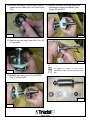
7) CONTROL BOX XE301P
NOTE:
All of the following checks are done without
power to the motor or hoist.
7-1 Tools Required
- Volt/Ohm meter (left in Figure 701)
- Digital Capacitor meter (up to 275uF)
- 2 insulated screwdrivers
Figure 703
3) Check that the protective cover around the
emergency stop button is in good condition
and is not loose. Replace it if necessary.
The 3 screws must be tightened and have
silicone applied to seal against water entry.
Figure 701
7-2 Control Box Cover Inspection
1) Check that all labels are legible and in the
right place (Figure 702). If not, replace
those labels. See sec. 9-2 for correct
location and code.
Figure 704
4) Check that the voltage indicator light is not
damaged (Figure 704).
7-3 Ground (Cord/Plug) Check
1) With an ohm meter, check each prong to the
case of the TIRAK. The long ground prong
should show continuity (Figure 705).
Figure 702
2) Check that the emergency stop button
functions normally. (Figure 703). Press it to
lock in the "Off" position. Twist it to check
that it springs open into the "On" position.
Check that it is not loose. If it is, open the
cover and tighten the 2 screws that hold it in
place.
52
Figure 705
The two shorter prongs should not show
continuity (Figure 706).
3) A full size diagram should be folded and
tucked in place next to the relays. Check that
the full size diagram matches the tag (Figure
Figure 706
NOTE:
If either of the shorter prongs show continuity to
ground, a short circuit has occurred and must be
fixed. It is possible that the plug is wired incorrectly or the insulation is cut. Open the plug and
investigate. Also check the cord grip.
Figure 709
709).
NOTE:
When using an ohm-meter, deduct the test probe
resistance from any reading for accuracy. Shown
as 0.2 ohms (Figure 710).
7-4 Wiring Diagram Location
1) Using a screwdriver, open the control box
(Figure 707).
Figure 710
Figure 707
2) A tag tied to wires indicates the control box
type, L10.3B, and wiring diagram, #34427
(Figure 708).
7-5 Stator/Winding Check
1) With an ohm-meter, measure the resistance
of the starting winding W/Z by placing test
probes on Position 1(W) and Position 2(Z) of
terminal board M1 (3.9 ohms is normal.
Figure 711 (on the next page), shows 4.0-0.2
= 1.73 ohms,OK). This is found on the wiring
diagram #34427. If the connection is open,
the stator must be replaced.
Figure 708
53
4) Check that the run winding is not shorted to
ground. There should be no continuity
between U or V and the control box casing
(Figure 714). If the connection is shorted, the
stator must be replaced.
Figure 714
Figure 711
2) Check that the starting winding is not shorted
to ground. There should be no continuity
between W or Z and the control box casing
(Figure 712). If the connection is shorted, the
stator must be replaced.
7-6 Fuse Check, F1 {Code #22366 (110V), Pos.
11, Code #21076 (220V), Pos. 13}
1) With an ohmmeter, check continuity by
placing the test probes on X1 and X2 of the
fuse. If no continuity is found, replace the
fuse with the spare by lifting the grey fuse
holder (Figure 715).
Figure 712
3) With an ohm-meter, measure resistance of
the run winding U/V by placing the test
probes on position 4(U) and position 5(V) of
terminal board M1 (.93 ohms is normal
Figure 713, shows 2.2-0.2 = 2.0 ohms). This
is found on the wiring diagram #34427. If the
connection is open, the stator must be
replaced.
Figure 715
NOTE:
The thermal protector opens when the motor is hot
in order to prevent damage. It is normally closed
and automatically resets.
7-7 Thermal Protector Check
With the ohmmeter, place the test probes on the
fuse terminal and X1 of the grey terminal board
where the two small wires are fixed (Figure 716
on the next page). If the connection is open, the
stator must be replaced.
Figure 713
54
3) The UP relay, K1, coil resistance should be
approximately 310 ohms. Place the
ohmmeter test probes on the A1 and A2
screws of the K3 relay. Check the
resistance (Figure 719, shows 305 ohms,
OK). If the connection is open or shorted,
replace the UP/DOWN double relay {Code
#60456 (110 V), #60466 (220 V) Pos. 8}.
Figure 716
7-8 Relay Coil Resistance, K1, K2, K3
1) Main relay K3 coil resistance should be
approximately 310 ohms. Place the
ohmmeter test probes on the A1 and A2
screws of the K3 relay. Check the
resistance (Figure 717, shows 315 ohms,
OK). If the connnection is open or shorted,
replace the K3 relay {Code #60406 (110 V),
#60356 (220 V), Pos. 7}.
Figure 719
7-9 Brake Coil Resistance Check
With the ohmmeter test probes placed on the
center two positive(+) and negative(-) terminals
of the brake rectifier U1, measure the resistance
(Figure 720, shows 333 ohms, OK). It should be
approximately 332 ohms. If the connection is
open or shorted, replace the brake coil .
Figure 717
2) The DOWN relay, K2, coil resistance should
also be approximately 310 ohms. Place the
ohmeter test probes on the A1 and A2 screws
of the K2 relay. Check the resistance (Figure
718, shows 312 ohms, OK). If the
connection is open or shorted, replace the
UP/DOWN double relay {Code #60456
(110 V), #60466 (220 V) Pos. 8}.
Figure 720
7-10 Capacitor Checks
1) Discharge the capacitors by sliding the K1 or
K2, and K3 relays to the right with 2 insulated
screwdrivers for several seconds (Figure
721 on the next page).
Figure 718
55
Figure 721
Figure 723
2) With a digital capacitor tester, measure the
start and run capacitance by placing the test
clips on position 4 and position 6 of the
terminal board M1 (Figure 722, shows 277uf,
OK). This number is the combination of the
start capacitor CA(180uF) + run capacitor(s)
CB(35uF) = 250uF +/- 10%. If the total is
outside this range, check each capacitor as
follows.
4) The run capacitor CB(35uF) is located in the
control box and is larger in size than the start
capacitor (Figure 724, shows 39uF, OK).
Detach the two insulated space connectors
from the capacitor and attach the digital
capacitor meter clips to the capacitor.
Measure the capacitance. It should read
35uF +/- 10% (32 to 38uF). If the reading is
outside this range, replace the run capacitor
{Code #23686 (110 V), #42766 (220 V),
Pos. 32}.
Figure 722
3) The start capacitor CA(180uF) is located on
the cover of the control box (Figure 723
shows 196uF, OK). Detach the two insulated
spade connectors. With the digital capacitor
meter, measure the capacitance. It should
be 180uF +/- 10% (162 to 198 uF). If the
reading is outside this range, replace the
start capacitor {Code #19196 (110 V),
#38546 (220 V, Pos. 31}.
56
Figure 724
Remember that all the previous tests/rules
also apply to the (20mF & 60mF) 220 V
Capacitors.
Note: The 220 V XE301P only contains one
run capaitor.
7-11 Centrifugal Switch Check
With an ohmmeter, place the the probes on
position 5 and 6 of the terminal board M1
(Figure 725 on the next page). The switch
should be closed when the motor is not
running. When the motor runs, the motor
draws high amps and the switch opens. If it
stays closed, it is stuck and the switch should
be repaired or replaced.
7-12 Pushbutton Checks
1) Contacts are marked NO = “Normally Open“
or NC = “Normally Closed”. Figure 726
shows continuity for a NC contact. If the
button is pressed it should open. A NO
switch operates in an opposite manner.
Pressing the button closes the switch and
creates continuity.
Figure 726
Figure 725
7-13 Control Box Check
1) Tighten the 4 socket head screws {Code
#33156, Pos. 37} that hold the control box to
the motor (Figure 727).
Figure 727
2) Check that the control box base is not
distorted or cracked especially at the junction
of the box to the motor. If damaged, it must
be replaced.
57
7-15 Power Check
WARNING
The following checks are performed with power to
the hoist motor. Whenever power is applied to the
hoist, use extreme caution especially with the
control box open as part are energized. Only trained
and qualified personnel should service the hoist to
avoid injury or death.
1) Open the emergency stop by twisting the red
knob. It should spring open. This should
cause the main relay, K3, to energize.
2) Measure the AC input voltage with a
voltmeter at terminal 1 and 3 of the K3 relay
(Figure 728). If no voltage occurs, check the
fuse and bimetal protector per sections 7-5.
Figure 729
3) The AC voltage to the rectifier should be the
same as the input power measured in
Section 7-12.
4) Measure the DC voltage from the rectifier.
Change the voltmeter to DC. Measure the
voltage output from the rectifier at the
positive(+) and negative(-) screw terminals (2
center screws) while pressing the UP or
DOWN button on the control box cover
(Figure 730, which shows 103.2 DC volts
from the rectifier, OK). It should read
approximately 110 volts. If not approximately
110 volts, replace the rectifier.
For 220 V XE301P: If not approximately
220 volts, replace the rectifier.
Figure 728
7-16 Brake Rectifier Check {Code #10917,
Pos. 10}
1) Push either the up or down button on the
control box cover. The motor should run.
2) While the motor is running, measure the AC
voltage to the brake rectifier by placing the
voltmeter probes on the AC screws of the
rectifier (left side terminals marked ~ ~). See
Figure 729 which shows 116.6 volts AC to
rectifier, OK.
58
Figure 730
NOTE:
General service on the control box is now
complete.
XE301P - 110V- Direct
Spare Parts
Position
1
2
3
4
6
7
8
9
10
11
12
13
14
15
17
18
19
21
22
23
24
25a
25b
27
28
29
30
31
32
33
(34*)
(35*)
37
38
40
41
43
44
46
47
48
Part #
26647
47917
17846
65115
22905
35435
60406
60456
22426
10917
22366
21076
40796
24346
18566
22856
21706
21716
21746
18296
37776
103
2311
6031
15026
18276
18256
25056
19196
23686
18906
10991
11021
33156
17016
33126
16
7536
16246
456
44466
44476
110V / 1ph. / 60Hz
GG 13/10.14
Qty.
1
1
1
1
1
1
1
1
1
1
1
2
1
3
2
1
2
2
1
1
1
1
1
1
1
1
1
2
1
2
1
8
3
4
2
5
5
4
4
4
1
1
Wiring Diagram #19225
Plan #19226
Description
Control box complete GG13/10.14, XE301
Terminal box, empty
GASKET
Angle bracket
Mounting rail
SWITCH PROTECTION
Contactor / Relay
Double Contactor / Relay
TERMINAL BOARD COMPLETE
RECTIFIER
FUSE BLOCK WITH PLATE
2 AMP FINE WIRE FUSE
EARTH BLOCK M4/6P
TERMINAL BLOCK
Identification labels 1-10
End plate
PUSH BUTTON BLOCK
PUSH BUTTON COVER
"EMERGENCY STOP" BUTTON BLOCK
"EMERGENCY STOP" BUTTON COVER
"EMERGENCY STOP" LABEL
Power cord for single phase, per ft.
Hubbell plug 20A 125V
Hubbell plug boot for 3 pol
CABLE BUSHING WITH STRAIN RELIEF PG21-MS
BLIND PLUG PG 16 MS
BLIND PLUG PG 11 MS
CABLE BUSHING PG 7
START CAPACITOR
WORKING CAPACITOR 350 VF 35 MF
PIPE CLAMP
Conductor (black)
INSOLATING TUBE 4.2X0.6
SOCKET HEAD CAP SCREW M5X16
CHEESE HEAD SKREW M3X12 DIN 84
CHEESE HEAD SCREW M4X10 DIN84
Cheese head screw
HEXAGON HEAD CAP SCREW 6X12 DIN 933
SPRING WASHER DIA.5 DIN 127
Washer
Label "UP"
Label "DOWN"
Drawing No
Edition
Date
Page
Specifications
110V, Direct
DK80-112R/02
25x100x3
35x180
LC1 K 09 10 F - 110V
LC2 K 09 10 F - 110V
5x20
ZB2BZ105 - NO+NC
ZB2BA78
ZB2BZ102 - NC
ZB2BS54
3 x 10 AWG
Pg. 21
Pg. 16
Pg. 11
Pg. 7
180 mF
35 mF
M5x15
M3x12
M4x10
M4x8
M6x12
A5
A6.4
E - 3068
US-1
1/05
1/2
List Price
$1,377.25
$0.00
$2.26
$0.00
$0.00
$64.98
$62.70
$141.82
$20.49
$55.46
$8.76
$1.26
$4.90
$2.80
$0.00
$0.00
$28.80
$19.63
$19.48
$31.73
$7.27
$0.00
$0.00
$0.00
$10.93
$1.51
$1.13
$1.61
$76.27
$82.33
$1.90
$0.00
$2.49
$0.50
$0.07
$0.26
$0.00
$1.05
$0.13
$0.00
$0.00
$0.00
Spare Parts
XE301P - 110V- Direct
110V / 1ph. / 60Hz
GG 13/10.14
Wiring Diagram #19225
Plan #19226
Drawing No
Edition
Date
Page
E - 3068
US-1
1/05
2/2
XE301P - 220V/1ph. - Direct
Spare Parts
Position
1
3
4
5
6
7
8
9
10
12
13
14
15
16
17
18
19
21
22
23
24
25a
25b
27
28
29
30
31
32
33
(34*)
(35*)
36
37
38
39
40
41
43
44
45
46
47
48
Part #
26637
42757
17846
43285
35805
35435
60356
60466
22426
10917
22366
21076
24346
18566
40796
22856
21706
21716
21746
18296
37776
103
2421
6031
15026
18256
23926
25056
38546
42766
18906
10991
11021
18276
33156
17016
10236
33126
7536
16616
16246
456
23616
44466
44476
220V / 1ph. / 60Hz
GG 13/10.3
Qty.
1
1
1
1
1
1
1
1
1
1
1
1
1
1
1
1
1
1
1
1
1
1
1
1
1
1
1
1
1
1
1
1
1
1
1
1
1
1
1
1
1
1
1
1
1
Wiring Diagram #19219
Plan #19220
Description
Terminal box complete XE301 220V
Control box, empty, XE301
GASKET
MOUNTING RAIL
Distance tube
SWITCH PROTECTION
Contactor / Relay
Double Contactor / Relay
TERMINAL BOARD COMPLETE
RECTIFIER
FUSE BLOCK WITH PLATE
2 AMP FINE WIRE FUSE
TERMINAL BLOCK
Identification labels 1-10
EARTH BLOCK M4/6P
End plate
PUSH BUTTON BLOCK
PUSH BUTTON COVER
"EMERGENCY STOP" BUTTON BLOCK
"EMERGENCY STOP" BUTTON COVER
"EMERGENCY STOP" LABEL
Power cord for single phase, per ft.
Hubbell plug 20A/250V/4 pole
Hubbell plug boot for 3 pol
CABLE BUSHING WITH STRAIN RELIEF PG21-MS
BLIND PLUG PG 11 MS
CABLE BUSHING PG 9
CABLE BUSHING PG 7
STARTING CAPACITOR 60MF XE301 220V XE701
RUN CAPACITOR
PIPE CLAMP
Conductor (black)
INSOLATING TUBE 4.2X0.6
BLIND PLUG PG 16 MS
SOCKET HEAD CAP SCREW M5X16
CHEESE HEAD SKREW M3X12 DIN 84
CHEESE HEAD SCREW M5X8 DIN84
CHEESE HEAD SCREW M4X10 DIN84
HEXAGON HEAD CAP SCREW 6X12 DIN 933
SPRING WASHER A6 DIN 127
SPRING WASHER DIA.5 DIN 127
Washer
HEXAGON NUT M5 DIN 934
Label "UP"
Label "DOWN"
Drawing No
Edition
Date
Page
Specifications
220V/1ph., Direct
DK80-112R/02
35x244
LC1 K 09 10 P - 220V
LC2 K 09 10 P - 220V
5x20
ZB2BZ105 - NO+NC
ZB2BA78
ZB2BZ102 - NC
ZB2BS54
3 x 10 AWG
Pg. 21
Pg. 11
Pg. 9
Pg. 7
60 mF
20 mF
Pg. 16
M5x15
M3x12
M5x8
M4x10
M6x12
A6
A5
A6.4
M5
E - 3061
US-1
1/05
1/2
List Price
$0.00
$0.00
$2.26
$12.18
$0.00
$64.98
$62.70
$141.82
$20.49
$55.46
$8.76
$1.26
$2.80
$0.00
$4.90
$0.00
$28.80
$19.63
$19.48
$31.73
$7.27
$0.00
$0.00
$0.00
$10.93
$1.13
$1.90
$1.61
$45.97
$105.31
$1.90
$0.00
$2.49
$1.51
$0.50
$0.07
$0.39
$0.26
$1.05
$0.13
$0.13
$0.00
$0.26
$0.00
$0.00
Spare Parts
XE301P - 220V/1ph. - Direct
220V / 1ph. / 60Hz
GG 13/10.3
Wiring Diagram #19219
Plan #19220
Drawing No
Edition
Date
Page
E - 3061
US-1
1/05
2/2
8-5 Wiring Connection of Stator XE301P
Figure 801
71
9) WIRE ROPE SPECIFICATION TIRAK
There seems to be some question as to selection of wire rope due to the many people offering wire rope today
Before Tractel chooses a supplier of wire rope we run an endurance test or cycle test to make certain that the rope functions well in the hoist and has good life. The European norms require 1000 cycles minimum, UL testing requires 500
cycles. We require 2000 cycles and test with a high-speed hoist 60 ft./ min. to give a more severe dynamic load to the
wire rope during starts and stops. After 2000 cycles we allow a certain number of broken wires ( not strands ) in a given
length of rope. Too many breaks are a test failure. We have no idea how or if other rope suppliers test a rope with our
hoist. We generally do not test other peoples ropes because it is time consuming and expensive to conduct. We would
be inundated with samples.
5 X 19 vs. 5 X 26 Construction 5 strands of 26 wires have smaller wires making up the strands. This provides greater
flexibility but smaller outside wires wear out faster during normal use. Smaller wires are less resistant to abrasion.
Therefore we primarily recommend 5 X 19. PI equipment often uses 5 X 26 because winders are part of the system and
it coils better.
Quality of Manufacture- If a good control is not made on the tension during manufacture, then a loose strand can
occur. This shows when lowering a load. It can cause a jam. Preforming requires that tension be monitored. To get a
high quality rope requires that high quality wires be used creating very tight tolerances. A poor zinc plating process can
cause slippage. Ropes must be lubricated properly or the friction coefficient is poor between the wire rope and the
sheave.There should not be a change in the diameter of the wire rope when worn.
Summary- There is much more to wire rope selection than number of strands and number of wires. Tractel supplies
only high quality and rigorously tested wire rope from a very few carefully selected and monitored manufacturers.
9-1 Wire Rope Specifications - XE301P (Page 1 of 2)
1st Choice
2nd Choice
Hoist Types:
Tirak
Tirak
Construction:
5 x 19
5 x 26
Strands
5
5
Wires per strand
19
26
Polypropylene splitfilm
same
Warrington Seale
same
8.4 mm +0 -0.3mm{8.1 - 8.4 mm} 5/16" approx.
{0.319 - 0.326” }
same
Minimum Breaking Load:
10,000 lbs. [4590 kg]
same
Material of Construction:
Galvanized Steel wire rope XIPS 200/220 n/ sq. mm
same
Right hand Regular Lay
same
Lubrication:
Core Lubricated
same
Preformed:
Yes
same
Core Type
Type
Diameter:
Rope Lay:
Table 1001
72
9-1 Wire Rope Specifications - XE301P (Page 2 of 2)
NOTE:
As of 2/15/2002, 5/16” diameter should be
used (as taken from various product
literature).
4 x 26
6 x 19
6 x 31
5 x 19
5 x 26
Skyclimber
CX1250
Compact
Alpha1000
Skyclimber
CS1250 IWRC/RC
Alpha1500 3/8
Hilo
Tirak/Saturn
all models
1st choice
L-series
Skyclimber
CX1250
Compact
Alpha1000
Tirak 3rd choice
T-series
X-series
Spider
Z-Mac1000 IWRC
SC40 IWRC
Saturn 3rd choice
35X series
32L series
Power Climber
PC400 IWRC/RC
Astro IWRC/FC
5/16 or 3/8
Power Climber
PC400 IWRC/FC
Power Climber
PC400, Astro
Compacted
Skyman
6 x17 IWRC
Lisbon Hoist
180-050
180-030
Tirak/Saturn
all models
2nd choice
(1st for reelers)
L-series
Saturn 4th choice
35X series
32L series
Tirak 4th choice
T-series
X-series
Table 1002
73
9-2 Labels and Nameplates
74
9-3 Checklist
NOTE:
Completion of the checklist MUST always
be done before operating the hoist.
75
9-4 Hoist Specification LE501P1
5x19 or 5x26 with
fiber core lubricated,
Wire rope classification/construction
preformed IPS or
XIPS
in.
5/16 in.
mm
8.4 mm
in.
0.319 to 0.331
mm
8.1 to 8.4
lbs
10,000
kN
44.5
nominal diameter
maximum allowed
diameter tolerances
minimum actual breaking
strength
Table 1003
Figure 1001
Hoist Model
XE301P
with BLOCSTOP model
BSO 500
lbs
700.0
kg
300.0
ft/min
35.0
Rated Load
Lifting Speed
m/min
11.0
lbs
77.0
kg
35.0
Weight (with BSO)
a
Dimensions over all
b
c
in.
28.9
mm
735.0
in.
11.2
mm
286.0
in.
12.5
mm
314.0
Motor Specifications
Single phase 110V / 60 cycles
Single phase 220V / 60 cycles
wire rope diameter
Kw
A
10.5
Kw
A
5.2
in.
5/16"
mm
8.4
Misc. Info:
- Hoist shall self reeve the wire rope
- Continuously duty motor TEFC
- Secondary brake shall be externally attached to the hoist
mechanism.
- Emergency lowering without power shall be by means of a
mechanical centrifugal brake.
76
TRACTEL Inc
GRIPHOIST Division
110, Shawmut Road
Canton, MA 02021
Tel: 800-421-0246
Fax: 781-828 3642
[email protected]
TRACTEL LTD
GRIPHOIST Division
11020 Mirabeau St
Anjou QUEBEC, H1J 2S3
Tel. +1 (514) 493 3332
Fax. +1 (514) 493 3342
[email protected]
© Copyright - All rights reserved
77
TRACTEL Inc
GRIPHOIST Division
Branch Office: 315 Cloverleaf Dr.
Building E Baldwin Park CA 91706
Tel. +1 (626) 937 6727
Fax. +1 (626) 937 6730