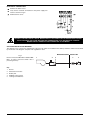
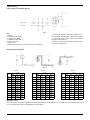
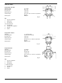
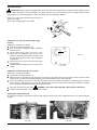
1
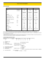
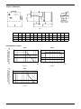
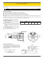
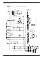
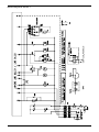
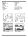
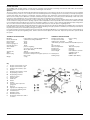
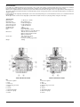
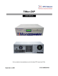
MANUAL OF
- INSTALLATION
- OPERATION
- MAINTENANCE
DUAL FUEL BURNERS
GAS - LIGHT OIL
HS5
HS10
HS18
M039118CA Rev. 0 04/03
Complying with
90 / 396 / CEE
GAS DIRECTIVE
Documentazione Tecnica CIB Unigas - Campodarsego (PD)
NOTICES
THIS MANUAL IS SUPPLIED AS AN INTEGRAL AND ESSENTIAL PART OF THE PRODUCT AND MUST BE DELIVERED
TO THE USER.
INFORMATION INCLUDED IN THIS SECTION ARE DEDICATED BOTH TO THE USER AND TO PERSONNEL FOLLOWING
PRODUCT INSTALLATION AND MAINTENANCE.
THE USER WILL FIND FURTHER INFORMATION ABOUT OPERATING AND USE RESTRICTIONS, IN THE SECOND SECTION OF THIS MANUAL. WE HIGHLY RECOMMEND TO READ IT.
CAREFULLY KEEP THIS MANUAL FOR FUTURE REFERENCE.
1)
2)
GENERAL INTRODUCTION
SPECIAL INSTRUCTIONS FOR BURNERS
z The equipment must be installed in compliance with the
z The burner should be installed in a suitable room, with ven-
regulations in force, following the manufacturer’s instructions, by qualified personnel.
z Qualified personnel means those having technical knowledge in the field of components for civil or industrial heating
systems, sanitary hot water generation and particularly service centres authorised by the manufacturer.
z Improper installation may cause injury to people and animals, or damage to property, for which the manufacturer
cannot be held liable.
z Remove all packaging material and inspect the equipment
for integrity.
In case of any doubt, do not use the unit - contact the supplier.
The packaging materials (wooden crate, nails, fastening devices, plastic bags, foamed polystyrene, etc), should not be left
within the reach of children, as they may prove harmful.
z Before any cleaning or servicing operation, disconnect the
unit from the mains by turning the master switch OFF, and/
or through the cut-out devices that are provided.
z Make sure that inlet or exhaust grilles are unobstructed.
z In case of breakdown and/or defective unit operation,
disconnect the unit. Make no attempt to repair the unit or
take any direct action.
Contact qualified personnel only.
Units shall be repaired exclusively by a servicing centre, duly
authorised by the manufacturer, with original spare parts.
Failure to comply with the above instructions is likely to impair
the unit’s safety.
To ensure equipment efficiency and proper operation, it is
essential that maintenance operations are performed by qualified personnel at regular intervals, following the manufacturer’s instructions.
z When a decision is made to discontinue the use of the
equipment, those parts likely to constitute sources of danger shall be made harmless.
z In case the equipment is to be sold or transferred to
another user, or in case the original user should move and
leave the unit behind, make sure that these instructions
accompany the equipment at all times so that they can be
consulted by the new owner and/or the installer.
z For all the units that have been modified or have options fitted then original accessory equipment only shall be used.
z This unit shall be employed exclusively for the use for
which it is meant. Any other use shall be considered as
improper and, therefore, dangerous.
The manufacturer shall not be held liable, by agreement or
otherwise, for damages resulting from improper installation,
use and failure to comply with the instructions supplied by the
manufacturer.
tilation openings complying with the requirements of the
regulations in force, and sufficient for good combustion.
z Only burners designed according to the regulations in force
should be used.
z This burner should be employed exclusively for the use for
which it was designed.
z Before connecting the burner, make sure that the unit
rating is the same as delivery mains (electricity, gas oil, or
other fuel).
z Observe caution with hot burner components. These are,
usually, near to the flame and the fuel pre-heating system,
they become hot during the unit operation and will remain
hot for some time after the burner has stopped.
When the decision is made to discontinue the use of the burner, the user shall have qualified personnel carry out the following operations:
a) Remove the power supply by disconnecting the power cord
from the mains.
b) Disconnect the fuel supply by means of the hand-operated
shut-off valve and remove the control handwheels from
their spindles.
Special warnings
z Make sure that the burner has, on installation, been firmly
secured to the appliance, so that the flame is generated
inside the appliance firebox.
z Before the burner is started and, thereafter, at least once a
year, have qualified personnel perform the following operations:
a) set the burner fuel flow rate depending on the heat input of
the appliance;
b) set the flow rate of the combustion-supporting air to obtain
a combustion efficiency level at least equal to the lower
level required by the regulations in force;
c) check the unit operation for proper combustion, to avoid
any harmful or polluting unburnt gases in excess of the
limits permitted by the regulations in force;
d) make sure that control and safety devices are operating
properly;
e) make sure that exhaust ducts intended to discharge the
products of combustion are operating properly;
f) on completion of setting and adjustment operations, make
sure that all mechanical locking devices of controls have
been duly tightened;
g) make sure that a copy of the burner use and maintenance
instructions is available in the boiler room.
z In case of repeated burner shut-downs, do not continue resetting the unit manually. Contact qualified personnel to
take care of such defects.
z The unit shall be operated and serviced by qualified personnel only, in compliance with the regulations in force.
2
NOTICES
3b) FIRING WITH GAS, LIGHT OIL OR OTHER FUELS
3) GENERAL INSTRUCTIONS DEPENDING ON FUEL
USED
3a) ELECTRICAL CONNECTION
z For safety reasons the unit must be efficiently earthed and
installed as required by current safety regulations.
z It is vital that all saftey requirements are met. In case of any
doubt, ask for an accurate inspection of electrics by qualified personnel, since the manufacturer cannot be held liable for damages that may be caused by failure to correctly
earth the equipment.
z Qualified personnel must inspect the system to make sure
that it is adequate to take the maximum power used by the
equipment shown on the equipment rating plate. In particular, make sure that the system cable cross section is adequate for the power absorbed by the unit.
z No adaptors, multiple outlet sockets and/or extension
cables are permitted to connect the unit to the electric
mains.
z An omnipolar switch shall be provided for connection to
mains, as required by the current safety regulations.
z The use of any power-operated component implies observance of a few basic rules, for example:
◆ do not touch the unit with wet or damp parts of the body
and/or with bare feet;
◆ do not pull electric cables;
◆ do not leave the equipment exposed to weather (rain,
sun, etc.) unless expressly required to do so;
◆ do not allow children or inexperienced persons to use
equipment;
z The unit input cable shall not be replaced by the user.
In case of damage to the cable, switch off the unit and contact
qualified personnel to replace.
When the unit is out of use for some time the electric switch
supplying all the power-driven components in the system (i.e.
pumps, burner, etc.) should be switched off.
GENERAL
z The burner shall be installed by qualified personnel and in
compliance with regulations and provisions in force; wrong
installation can cause injuries to people and animals, or
damage to property, for which the manufacturer cannot be
held liable.
z Before installation, it is recommended that all the fuel supply system pipes be carefully cleaned inside, to remove
foreign matter that might impair the burner operation.
z Before the burner is commissioned, qualified personnel
should inspect the following:
a) the fuel supply system, for proper sealing;
b) the fuel flow rate, to make sure that it has been set based
on the firing rate required of the burner;
c) the burner firing system, to make sure that it is supplied for
the designed fuel type;
d) the fuel supply pressure, to make sure that it is included in
the range shown on the rating plate;
e) the fuel supply system, to make sure that the system
dimensions are adequate to the burner firing rate, and that
the system is equipped with all the safety and control devices required by the regulations in force.
z When the burner is to remain idle for some time, the fuel
supply tap or taps should be closed.
SPECIAL INSTRUCTIONS FOR USING GAS
Have qualified personnel inspect the installation to ensure
that:
a) the gas delivery line and train are in compliance with the
regulations and provisions in force;
b) all gas connections are tight;
c) the boiler room ventilation openings are such that they
ensure the air supply flow required by the current regulations, and in any case are sufficient for proper combustion.
z Do not use gas pipes to earth electrical equipment.
z Never leave the burner connected when not in use. Always
shut the gas valve off.
z In case of prolonged absence of the user, the main gas
delivery valve to the burner should be shut off.
Precautions if you can smell gas
a) do not operate electric switches, the telephone, or any
other item likely to generate sparks;
b) immediately open doors and windows to create an air flow
to purge the room;
c) close the gas valves;
d) contact qualified personnel.
z Do not obstruct the ventilation openings of the room where
gas appliances are installed, to avoid dangerous conditions
such as the development of toxic or explosive mixtures.
NOTICES
3
PART I: INSTALLATION MANUAL
SPECIFICATIONS
BURNER MODEL
Output
HS5
HS10
HS18
min. kW
35
65
80
max. kW
70
140
200
Natural gas
Light oil
Natural gas
Light oil
Natural gas
Light oil
I2H
I2H
I2H
3.7 - 7.5
6.9 - 15
8.5 - 21
Fuel
Category
Gas rate min - max
Stm 3/h
Light oil rate min - max
Kg/h
3-6
5.5 - 12
7 - 17
Gas pressure min.* - max.
mbar
20 - 200
20 - 200
20 - 200
230 V - 50 Hz
230 V - 50 Hz
230 V - 50 Hz
Power supply - frequency
Fan motor
kW
0.1
0.15
0.15
Pump motor
kW
0.1
0.1
0.1
Total power consumption
kW
0.25
0.25
0.25
IP40
IP40
IP40
20
27
27
1/2”
3/4”
1”
Rp1/2
Rp3/4
Rp1
single stage
single stage
single stage
*
*
*
Protection
Weight
Valves size
Gas connection
Operation
Destination country
Kg
Note: all gas flow rates (Stm 3/h) are referred to standard gas conditions: 1013 mbar pressure, 15 °C temperature.
Flow rates are referred to G20 natural gas (nett calorific value: 34.02 MJ/Stm3), if G25 is used (n.c.v.: 29.25 MJ/Stm 3), flow rates
must be multiplied by 1.16 factor.
* Minimum pressure to get the maximum rate with any value of back pressure in combustion chamber. The burner operates correctly also with lower pressures but these must guarantee the needed rate.
BURNER MODEL IDENTIFICATION
Burners are identified by burner type and model. Burner model identification is described here following.
Type: HS5
Model:
MG.
PR. S.
*.
A.
0.
40
(1)
(2)
(3)
(4)
(5)
(6)
(7)
(8)
(1)
(2)
(3)
(4)
(5)
(6)
(7)
(8)
4
BURNER TYPE
FUEL
OPERATION
BLAST TUBE LENGHT
MG - Natural gas / Light oil
Available versions TN - Single stage
(see overall dimensions)
Available versions S - Standard
L - Long
DESTINATION COUNTRY
* - see data plate
SPECIAL VERSIONS
A - Standard
EQUIPMENT
Available versions 0 - 2 Valves
1 - 2 Valves + leak detection monitor (on request if output < 1200 kW)
GAS TRAIN SIZE
(see specifications)
15= Rp1/2
20=Rp3/4
25= Rp1
OVERALL DIMENSIONS
Dima di foratura
piastra caldaia
Fig. 1
A
B
BL
C
CL
D
E
G
K
H
Pmin Pmax
M
HS5
320
60
160
380
480
400
230
80
19
90
92
134
M8
HS10
350
160
255
510
605
430
255
108
210
115
105
134
M8
HS18
350
175
265
525
615
430
255
125
210
135
105
134
M8
BACK PRESSURE IN
CONBUSTION CHAMBER mbar
PERFORMANCE CURVES
HS5
HS10
2,5
4
3,5
2
3
1,5
2,5
1
1,5
2
1
0,5
0,5
0
0
28
32
36
40
44
48
52
56
60
64
68
72
76
Fig. 2a
BACK PRESSURE IN
CONBUSTION CHAMBER mbar
50
60
70
80
90
kW
100
110
120
130
kW
Fig. 2b
HS18
5
4
3
2
1
0
60
80
100
120
140
160
180
200
220
kW
Fig. 3a
5
MOUNTINGS AND CONNECTIONS
Packing
The burners are despatched in cardboard packages of dimensions:
Type
Model
L
A
P
HS5
HS5
HS10
HS10
HS18
HS18
M-.TN.S.*.A.0.15
M-.TN.L.*.A.0.15
M-.TN.S.*.A.0.20
M-.TN.L.*.A.0.20
M-.TN.S.*.A.0.25
M-.TN.L.*.A.0.25
360
360
420
420
420
420
460
560
620
700
620
700
300
300
340
340
340
340
Packing cases of this kind are affected by humidity and are not suitable for stacking. The following are placed in each packing
case.
1
burner with detached gas train
1
gasket to be inserted between the burner and the boiler;
1
envelope containing this manual
To get rid of the burner’s packing and in the event of scrapping of the latter, follow the procedures laid down by current laws on
disposal of materials.
Fitting the burner to the boiler
Fix the flange of the burner to the boiler as shown in Fig. 4.
This allow a correct inclination towards the combustion chamber. If necessary, after fitting the burner to the boiler, seal the
space between the blast tube and the refractory lining with
appropriate insulating material (ceramic fibre cord or refractory
cement).
Fig. 4
Matching the burner to the boiler
The burners described in this manual have been tested with combustion chambers that comply with EN676 regulation and
whose dimensions are described in the diagram in Fig. 5. In case the burner must be coupled with boilers with a combustion
chamber smaller in diameter or shorter than those described in the diagram, please contact the supplier, to verify that a correct
matching is possible, with respect of the application involved.
To correctly match the burner to the boiler verify the necessary input and the pressure in combustion chamber are included in
the burner performance curve; otherwise the choice of the burner must be revised consulting the burner manufacturer.
To choose the blast tube lenght follow the instructions of the boiler manufacturer. In absence of these consider the following:
z Cast-iron boilers, three pass flue boilers (with the first pass in the rear part): the blast tube must protrude no more than 100
mm into the combustion chamber.
The length of the blast tubes does not always allow this requirement to be met, and thus it may be necessary to use a suitablysized spacer to move the burner backwards.
z Pressurised boilers with flame reversal: in this case the blast tube must penetrate at least 50 - 100 mm into combustion
chamber in respect to the tube bundle plate.
Key
a) Heat input Q in kW
b) Lenght of the flame tube in meters
c) Flame tube firing intensity in MW/m 3
d) Combustion chamber diameter (m)
Fig. 5 - Firing intensity, diameter and lenght of the test flame tube
as a function of the heat input Q.
6
ELECTRICAL CONNECTIONS
z
z
z
Remove the burner cover.
Carry out the electrical connections to the power supply connector as shown in Fig. 6.
Refit the burner cover.
Fig. 6
RESPECT THE BASIC SAFETY RULES. MAKE SURE OF THE CONNECTION TO THE EARTHING SYSTEM.
DO NOT REVERSE THE PHASE AND NEUTRAL CONNECTIONS. FIT A DIFFERENTIAL THERMAL
MAGNET SWITCH ADEQUATE FOR CONNECTION TO THE MAINS.
GAS TRAIN INSTALLATION DIAGRAM
The diagram in Fig. 7 shows the components of the gas train which are included in the delivery and those which must be fitted
by the installer. The diagrams complies with regulations in force
Fig. 7
Burners fitted with Multibloc DUNGS MBDLE... (2 valves + pressure switch + filter +
pressure governor)
MANUFACTURER
1
4
5
INSTALLER
3
2
Key
1 Burner
2 Manual shut-off valve
3 Bellow joint
4 Multibloc valves group
5 Leakage control device
7
SETTINGS
Gas settings
WARNING!
THE SEALED SCREWS MUST NOT BE UNLOOSED!
IN A SUCH CASE THE DEVICE WARRANTY IS IMMEDIATELY INVALIDATE!
.
Fig. 8 - Multibloc MB-DLE - VPS504
The multibloc unit is a compact unit consisting of two valves, gas
pressure switch, pressure stabilizer and gas filter. It can be paired
jointly to the Dungs VPS504 sealing controls.
The valve is adjusted by means of the RP regulator after slackening the locking screw VB by a number of turns. By unscrewing the
regulator RP the valve opens, screwing the valve closes.
To set the fast opening remove cover T, reverse it upside down and
use it as a tool to rotate screw VR. Clockwise rotation reduces start
flow rate, anticlockwise rotation increases it.
Do not use a screwdriver on the screw VR!
The pressure stabilizer is adjusted by operating the screw VS located under the cover C. By screwing down the pressure is increased
and by unscrewing it is reduced.
Note: the screw VSB must be removed only in case of replacemente of the coil.
Leakage control device VPS504 (Optional)
The VPS504 check the operation of the seal of the gas shut off valves costituting the MB-DLE. This check, carried out as soon as the
boiler thermostat gives a start signal to the burner, creates, by
means of the diaphragm pump inside it, a pressure in the test
space of 20 mbar higher than the supply pressure. When wishing to
monitor the test, install a pressure gauge ranged to that of the pressure supply point PA. If the test cycle is satisfactory, after a few
seconds the consent light LC (yellow) comes on. In the opposite
case the lockout light LB (red) comes on.
To restart it is necessary to reset the appliance by pressing the illuminated pushbutton LB.
8
C
VS T(VR)
VSB
RP
LC
LB
VB
PA
Fig. 8
Light oil settings
Light oil piping installation diagram
From tank
To tank
Fig. 9
Key
1 Burner
2 Flexible hoses (fitted)
3 Light oil filter (fitted)
4 Automatic interceptor (*)
5 One-way valve (*)
6 Gate valve
7 Quick-closing gate-valve (not in vicinity of tank or boiler)
(*) Only for installations with gravity, siphon or forced circulation feed systems. If the device installed
is a solenoid valve, a timer must be installed to
delay the valve opening.
The direct connectionof the device without a timer
may cause pump breaks
Sizing the light oil pipeline
Fig. 10
Tab. 1
Tab. 2
L (m)
H
(m)
Ø6
Ø8
0
41
100
Tab. 3
L (m)
Ø 10
H
(m)
Ø6
Ø8
Ø 10
100
0
19
77
100
L (m)
Ø 12
H
(m)
Ø6
Ø8
Ø 10
Ø 12
100
0
18
73
100
100
0.5
70
100
100
1
24
90
100
100
0.5
15
66
100
100
1
100
100
100
2
30
100
100
100
1
13
59
100
100
1.5
100
100
100
3
34
100
100
100
1.5
10
52
100
100
2
100
100
100
4
39
100
100
100
2
7
44
100
100
2.5
100
100
100
5
44
100
100
100
2.5
5
44
100
100
3
100
100
100
6
48
100
100
100
2.5
-
37
100
100
3.5
100
100
100
7
52
100
100
100
3
-
30
85
100
4
100
100
100
8
56
100
100
100
3.5
-
23
68
100
4.5
100
100
100
9
55
100
100
100
4
-
-
-
100
5
100
100
100
10
51
100
100
100
4.5
-
-
-
-
Monotube systen
The burners leave the factory equipped for twin-tube feed. They can be adapted for a mono-tube system (recommended in the
case of gravity feed). Refer to the Appendix for further details.
9
SETTINGS
Oil rate adjustment
The oil rate is set choosing a properly sized nozzle and adjusting the feeding pressure to the nozzle, in the pump (see principle
diagram of the light oil ring in Fig. 9).
To choose the proper nozzle refer to Tab. 4; to set the pump pressure see technical data on Page 11. For further informations
on oil pumps see the appendix.
Starting the pump
Before carrying out the adjustment it is necessary to start up the oil pump proceeding as follows:
z before operating the burner, make sure that the return pipe to the tank is not obstructed. Any obstruction would cause the
pump seal to break.
z Start the burner, light up the photoresistance after opening the solenoid valve and let the air escape from the pressure gauge
connection.
Key
EV1
EV2
M
P
Light oil solenoid valve
Light oil solenoid valve
Pressure gauge
Pump
P
Fig. 11
Burners HS5 - HS10
EV
M
Pump pressure
EV1
HS5 - HS10
12 bar
P
HS18
first stage, 8 bar
second stage, 18 bar
Fig. 12
Burners HS18
EV2
M
PUMP PRESSURE Bar
Nozzle
G.P.H.
8
9
10
11
12
13
14
15
16
17
18
0.40
0.50
0.60
0.65
0.75
0.85
1.00
1.10
1.20
1.25
1.35
1.50
1.65
1.75
2.00
2.25
2.50
3.00
3.50
1.36
1.70
2.04
2.21
2.55
2.89
3.40
3.74
4.08
4.25
4.59
5.10
5.61
5.95
6.80
7.64
8.49
10.19
11.89
1.44
1.80
2.16
2.34
2.70
3.06
3.60
3.96
4.32
4.50
4.86
5.41
5.95
6.31
7.21
8.11
9.01
10.81
12.61
1.52
1.90
2.28
2.47
2.85
3.23
3.80
4.18
4.56
4.75
5.13
5.70
6.27
6.65
7.60
8.55
9.50
11.40
13.29
1.59
1.99
2.39
2.59
2.99
3.39
3.98
4.38
4.78
4.98
5.38
5.98
6.57
6.97
7.97
8.96
9.96
11.95
13.94
1.66
2.08
2.50
2.70
3.12
3.54
4.16
4.58
4.99
5.20
5.62
6.24
6.87
7.28
8.32
9.36
10.40
12.48
14.56
1.73
2.17
2.60
2.82
3.25
3.68
4.33
4.76
5.20
5.41
5.85
6.50
7.15
7.58
8.66
9.74
10.83
12.99
15.16
1.80
2.25
2.70
2.92
3.37
3.82
4.49
4.94
5.39
5.62
6.07
6.74
7.42
7.87
8.99
10.11
11.24
13.48
15.73
1.86
2.33
2.79
3.02
3.49
3.95
4.65
5.12
5.58
5.82
6.28
6.98
7.68
8.14
9.30
10.47
11.63
13.96
16.28
1.92
2.40
2.88
3.12
3.60
4.08
4.80
5.29
5.77
6.01
6.49
7.21
7.93
8.41
9.61
10.81
12.01
14.41
16.82
1.98
2.48
2.97
3.22
3.71
4.21
4.95
5.45
5.94
6.19
6.69
7.43
8.17
8.67
9.91
11.14
12.38
14.86
17.33
2.04
2.55
3.06
3.31
3.82
4.33
5.10
5.61
6.12
6.37
6.88
7.64
8.41
8.92
10.19
11.47
12.74
15.29
17.84
Tab. 4
10
LIGHT OIL PUMPS
Pump Suntec AT2 45A
Viscosity range
Oil temperature
Inlet pressure
Return pressure
Suction height
Rated speed
2 ÷ 12 cSt
60°C max
2 bar max.
2 bar max.
max. 0,35 bar to avoid air separation
from oil.
3600 rpm
Fig. 13
Key
1
2
3
4-4a
5
6
7
8
Pressure regulation
Manometer
Vacuumeter
Solenoid valve
To oil nozzle
Low pressure regulation
Suction
Return
Pump Suntec AS47 A
Viscosity
Fuel temperature
Inlet pressure
Return pressure
Suction height
Rated speed
2 - 12 mm²/s (cSt)
0 - 60 °C into the pump
2 bar max.
2 bar max.
0,45 bar max. to avoid air separation
from oil.
3600 rpm max.
Fig. 14
Pumps Delta VM
Viscosity
Oil temperature
Inlet pressure
Return pressure
Suction height
Rated speed
2 ÷ 50 cSt
60°C max
0,7 bar max.
1,5 bar max.
max. 0,5 bar to avoid air separation
from oil.
3500 rpm
Fig. 15
Key
1
Pressure regulation
2
Manometer
3
Vacuumeter
4 - 4aSolenoid valve
5
To oil nozzle
7
Suction
8
Return
11
AIR RATE SETTING
ATTENTION: During commissioning operations, do not to let the burner operate with insufficient air flow (danger of formation of carbon monoxide); if this should happen, shut down the burner, increase the opening of the air damper and start up the
burner again to ensure the purging of the carbon monoxide from the combustion chamber.
Slacken the screw VBS and manually rotate the air
damper as needed.
At the end of settings tight the screw VBS.
-
VBS
+
Fig. 16
Calibration of air pressure switch (single stage
burners)
Calibration is carried out as follows:
z Remove the transparent plastic cap.
z After air and gas setting have been completed,
start the burner.
z The pre-purge phase starts; wait 10 sec. then
slowly turn the adjusting ring nut VR in the
clockwise direction until the burner lockout, read
the value on the pressure switch scale and reduce
it by 0.5 mbar.
z Repeat the start up cycle of the burner and check
it runs properly.
z Refit the transparent plastic cover on the pressure
switch.
VR
Fig. 17
Calibration of minimum gas pressure switch
Calibration is carried out as follows:
z Remove the transparent plastic cap.
z With the burner in operation test the pressure on the pressure port at the input of the gas filter; slowly close the manual
shut-off valve (see gas train installation diagram) until the detected pressure is reduced by 50%.
z Verify CO emissions of the burner; if the measured value is less than 80 ppm screw down the adjusting ring nut until the
burner lockout. If CO emissions are greater than 80 ppm open the shut off valve until the CO value is reduced to 80 ppm,
then screw down the adjusting ring nut until the burner lockout.
z
Fully open the manual shut-off valve
z
Refit the transparent plastic cover on the pressure switch.
WARNING: carry out this operation ONLY with the burner turned off!
Adjusting the combustion head
To adjust the combustion head rotate the ring nut VR. Rotate clockwise toclose the combustion head or turn counterclockwise
to open it.
VR
VR
Fig. 18a
12
Fig. 18b
PART II: OPERATION MANUAL
LIMITATIONS OF USE
THE BURNER IS AN APPLIANCE DESIGNED AND CONSTRUCTED TO OPERATE ONLY AFTER BEING CORRECTLY
CONNECTED TO A HEAT GENERATOR (E.G. BOILER, HOT AIR GENERATOR, FURNACE, ETC.), ANY OTHER USE IS TO
BE CONSIDERED IMPROPER AND THEREFORE DANGEROUS.
THE USER MUST GUARANTEE THE CORRECT FITTING OF THE APPLIANCE, ENTRUSTING THE INSTALLATION OF IT
TO QUALIFIED PERSONNEL AND HAVING THE FIRST COMMISSIONING OF IT CARRIED OUT BY A SERVICE CENTRE
AUTHORISED BY THE COMPANY MANUFACTURING THE BURNER.
A FUNDAMENTAL FACTOR IN THIS RESPECT IS THE ELECTRICAL CONNECTION TO THE GENERATOR’S CONTROL
AND SAFETY UNITS (CONTROL THERMOSTAT, SAFETY, ETC.) WHICH GUARANTEES CORRECT AND SAFE FUNCTIONING OF THE BURNER.
THEREFORE, ANY OPERATION OF THE APPLIANCE MUST BE PREVENTED WHICH DEPARTS FROM THE INSTALLATION OPERATIONS OR WHICH HAPPENS AFTER TOTAL OR PARTIAL TAMPERING WITH THESE (E.G. DISCONNECTION, EVEN PARTIAL, OF THE ELECTRICAL LEADS, OPENING THE GENERATOR DOOR, DISMANTLING OF PART OF
THE BURNER).
NEVER OPEN OR DISMANTLE ANY COMPONENT OF THE MACHINE.
OPERATE ONLY THE MAIN SWITCH, WHICH THROUGH ITS EASY ACCESSIBILITY AND RAPIDITY OF OPERATION
ALSO FUNCTIONS AS AN EMERGENCY SWITCH, AND ON THE RESET BUTTON.
IN THE EVENT OF REPEATED LOCKOUTS, DO NOT PERSIST WITH THE RESET BUTTON AND CONTACT QUALIFIED
PERSONNEL WHO WILL PROCEED TO ELIMINATE THE MALFUNCTION.
WARNING: DURING NORMAL OPERATION THE PARTS OF THE BURNER NEAREST TO THE GENERATOR (COUPLING
FLANGE) CAN BECOME VERY HOT, AVOID TOUCHING THEM SO AS NOT TO GET BURNT
OPERATION
z Choose the fuel with the switch B in Fig. 19, located on the burner casing.
z Turn on the power supply with the main switch A in Fig. 19.
z Check the flame control device is not lock, eventually release it by means of the pushbutton located on the hole on the burner casing.
z Check the series of thermostats (or pressure switches) enable the burner to operate.
z The start cycle of the burner begins, the flame controller starts the burner fan and meanwhile energizes the ignition transformer.
z At the end of the pre-purge, the solenoid valve of the selected fuel and the ignition transformer are both energized and the
burner starts.
z The ignition transformer remains in operation for any seconds after the flame appears (post-ignition time) and after this time
it is sutted off.
ONLY BURNERS HS18: at the end of the safety time the flame controller energizes the second light oil solenoid valve.
A
B
Fig. 19
PART II: OPERATION MANUAL
13
PART III: MAINTENANCE MANUAL
At least once a year carry out the maintenance operations listed below. In the case of seasonal servicing, it is recommended to
carry out the maintenance at the end of each heating season; in the case of continuous operation the maintenance is carried out
every 6 months.
WARNING: All operations on the burner must be carried out with the mains disconnected!
PERIODICAL SERVICING
z Clean and examine the oil filter cartridge and replace it if necessary.
z Examine the condition of the oil flexible hoses and check for possible leaks.
z Clean and examine the filter inside the oil pump (see instructions in the Appendìx).
z Dismantle, examine and clean the combustion head and when reassembling be carefully to respect the measures shown in
Tab. 5
z Check the detection photocell, clean it and adjust the position if needed and, if necessary, replace it. If in doubt, check the
detection circuit after the burner has been restarted, following the diagram in Fig. 20.
Correct position of electrodes and combustion
head (Fig. 19a e Fig. 19b)
z Prepare a stable surface where lean the burner
during maintenance.
z To gain access to the combustion head and to
the nozzles, slacken the screw on the blast tube
and remove it from the part that remains fixed to
the boiler.
z To guarantee a good ignition, respect the measures indicated in Tab. 5.
z Be sure to tight the screw that fix the electrodes
group, before reassembly the burner.
Tab. 5
HS5 - 10 - 18
NOZZLE
A
B
C
D
45°
3
2,5
3
7÷8
G
GAS
OIL
GAS
Fig. 19a
Fig. 19b
Check of the ionization current
See the diagram in Fig. 20 to measure the detection current. If the signal doesn’t suit the suggested value, verify
the electric terminals, the cleaning of the combustion
head and the position of the photoelectric cell and
replace it if required
Scale µA DC
Minimum current intensity with flame,
200 µA
Maximum possible current intensity
with flame, 500µA
Fig. 20
14
PART III: MAINTENANCE MANUAL
ELECTRICAL DIAGRAMS
Complete key
AGQ1.1A27
CM
CO
CR1
EV1
EV2
EVG
EVG1
EVG2
F
FC
IL
L
LB
LF
LGB..
MA
MP
MV
N
R1
ST
TA
TS
Auxiliary equipmet for UV photocells
Manual selector NATURAL GAS / LIGHT OIL
Time counter
Auxiliary relais contactd
Gas solenoid valve, network side (or valves group)
Gas solenoid valve, burner side (or valves group)
Light oil solenoid valve
Light oil solenoid valve, 1st stage
Light oil solenoid valve, 2nd stage (soft start)
Fuse
Flame detetion UV probe
Mains switch
Phase
Burner lock-out signalling lamp
Burner operation signalling lamp
LANDIS flame controller
Power supply terminal board
Light oil pump motor
Fan motor
Neutral
Auxiliary relay
Thermostats or pressure switches serie
Ignition transformer
Safety thermostat/pressure switch on boiler
ATTENTION
1 - Power supply 230V 50Hz 2N a.c.
2 - Don’t reverse phase with neutral
3 - Ensure the burner is properly hearthed
PART III: MAINTENANCE MANUAL
15
Electrical diagram 01-348 Rev. 2
16
PART III: MAINTENANCE MANUAL
Electrical diagram 01-352 Rev. 1
PART III: MAINTENANCE MANUAL
17
SPARE PARTS
DESCRIPTION
HS5
PHOTOCELL ADAPTER AGQ1.1A27
2510101
FLAME CONTROL DEVICE
2020443
FLAME CONTROL DEVICE SOCKET
2030415
COIL FOR DANFOSS SOLENOID VALVE
2580701
COIL FOR DELTA SOLENOID VALVE
2580406
COIL FOR SUNTEC SOLENOID VALVE
2580402
COIL FOR MULTIBLOC
2580018
COMPLETE BLAST TUBE, STANDARD
3090073
COMPLETE BLAST TUBE, LONG
3090087
IGNITION CABLE
6050122
CONDENSER FOR PUMP MOTOR
6030005
CONDENSER FOR FAN MOTOR
6030005
FEMALE CONNECTOR, 7 POLES
6200043
MALE CONNECTOR, 7 POLES
6200042
LEAK CONTROL DEVICE (optional)
2191604
IGNITION ELECTRODE
2080245
FILTER
2090001
FLANGE FOR MULTIBLOC
2191518
BURNER SLIDING FLANGE
2100025
FLEXIBLE HOSE
2340001
PHOTOCELL
2510001
COMPLETE PUMP COUPLING
2540016
MULTIBLOC VALVES GROUP
2190339
GASKET
2110027
TRANFORMATION KIT FOR SHORT TO LONG BLAST TUBE
3091147
TRANFORMATION KIT FOR LONG TO SHORT BLAST TUBE
3091227
PUMP MOTOR
2180004
FAN MOTOR
2180013
PUMP DANFOSS BFP21R3R
2590309
PUMP DELTA VM1RL2
2590012
PUMP SUNTEC AS47A
2590130
AIR PRESSURE SWITCH
2160053
MINIMUM GAS PRESSURE SWITCH
2160076
FLAME CONTROLLER SUPPORT BRACKET
3050014
COMBUSTION HEAD WITH ELECTRODES (STANDARD)
3501701
COMBUSTION HEAD WITH ELECTRODES (LONG)
3501702
TRANSFORMER
2170106
NOZZLE (SPECIFY SPRAY ANGLE AND OIL RATE)
2610002
FAN
2150003
DOUBLE SWITCH (ON-OFF AND FUEL SELECTION)
6170005
18
PART III: MAINTENANCE MANUAL
DESCRIPTION
HS10
PHOTOCELL ADAPTER AGQ1.1A27
2510101
FLAME CONTROL DEVICE
2020443
FLAME CONTROL DEVICE SOCKET
2030415
COIL FOR DANFOSS SOLENOID VALVE
2580701
COIL FOR DELTA SOLENOID VALVE
2580406
COIL FOR SUNTEC SOLENOID VALVE
2580402
COIL FOR MULTIBLOC
2580018
COMPLETE BLAST TUBE, STANDARD
3090074
COMPLETE BLAST TUBE, LONG
3090094
IGNITION CABLE
6050122
CONDENSER FOR PUMP MOTOR
6030003
CONDENSER FOR FAN MOTOR
6030003
CONDENSER FOR FAN MOTOR (alternate)
6030005
FEMALE CONNECTOR, 7 POLES
6200043
MALE CONNECTOR, 7 POLES
6200042
LEAK CONTROL DEVICE (optional)
2191604
IGNITION ELECTRODE
2080246
FILTER
2090001
FLANGE FOR MULTIBLOC
2190366
FLEXIBLE HOSE
2340001
PHOTOCELL
2510001
COMPLETE PUMP COUPLING
2540016
MULTIBLOC VALVES GROUP
2190340
GASKET
2110031
TRANFORMATION KIT FOR SHORT TO LONG BLAST TUBE
3091148
TRANFORMATION KIT FOR LONG TO SHORT BLAST TUBE
3091228
PUMP MOTOR
2180004
FAN MOTOR
2180703
FAN MOTOR (alternate)
2180005
PUMP DANFOSS BFP21R3R
2590309
PUMP DELTA VM1RL2
2590012
PUMP SUNTEC AS47A
2590130
AIR PRESSURE SWITCH
2160053
MINIMUM GAS PRESSURE SWITCH
2160076
FLAME CONTROLLER SUPPORT BRACKET
3050015
COMBUSTION HEAD WITH ELECTRODES (STANDARD)
3501703
COMBUSTION HEAD WITH ELECTRODES (LONG)
3501704
TRANSFORMER
2170106
NOZZLE (SPECIFY SPRAY ANGLE AND OIL RATE)
2610002
FAN
2150004
DOUBLE SWITCH (ON-OFF AND FUEL SELECTION)
6170005
PART III: MAINTENANCE MANUAL
19
DESCRIPTION
HS18
PHOTOCELL ADAPTER AGQ1.1A27
2510101
FLAME CONTROL DEVICE
2020443
FLAME CONTROL DEVICE SOCKET
2030415
COIL FOR SUNTEC SOLENOID VALVE
2580402
COIL FOR MULTIBLOC
2580017
COMPLETE BLAST TUBE, STANDARD
3090075
COMPLETE BLAST TUBE, LONG
3090098
IGNITION CABLE
6050122
CONDENSER FOR PUMP MOTOR
6030005
CONDENSER FOR FAN MOTOR
6030005
CONDENSER FOR FAN MOTOR (alternate)
6030005
FEMALE CONNECTOR, 7 POLES
6200043
MALE CONNECTOR, 7 POLES
6200042
LEAK CONTROL DEVICE (optional)
2191604
IGNITION ELECTRODE
2080246
FILTER
2090016
FLANGE FOR MULTIBLOC
2190367
FLEXIBLE HOSE
2340001
PHOTOCELL
2510001
COMPLETE PUMP COUPLING
2540016
MULTIBLOC VALVES GROUP
2190341
GASKET
2110031
TRANFORMATION KIT FOR SHORT TO LONG BLAST TUBE
3091149
TRANFORMATION KIT FOR LONG TO SHORT BLAST TUBE
3091229
PUMP MOTOR
2180004
FAN MOTOR
2180703
FAN MOTOR (alternate)
2180005
PUMP SUNTEC AT245A
2590152
AIR PRESSURE SWITCH
2160053
MINIMUM GAS PRESSURE SWITCH
2160076
FLAME CONTROLLER SUPPORT BRACKET
3050015
COMBUSTION HEAD WITH ELECTRODES (STANDARD)
3501705
COMBUSTION HEAD WITH ELECTRODES (LONG)
3501706
TRANSFORMER
2170106
NOZZLE (SPECIFY SPRAY ANGLE AND OIL RATE)
2610002
FAN
2150004
DOUBLE SWITCH (ON-OFF AND FUEL SELECTION)
6170005
20
PART III: MAINTENANCE MANUAL
APPENDIX - COMPONENTS CHARACTERISTICS
LANDIS LGB 21/22.. FLAME CONTROLLER
22
GAS MULTIBLOC REGULATOR DUNGS MB-DLE 405-407-410-412-415-420
25
VALVE PROVING SYSTEM DUNGS VPS504
25
SUNTEC AT2 PUMP
26
SUNTEC PUMPS AS 47 - 57 - 67
27
DELTA VM PUMPS
28
NOTES FOR USE AND MAINTENANCE OF FUEL PUMPS
29
21
APPENDIX - COMPONENTS CHARACTERISTICS
LANDIS LGB 21/22.. FLAME CONTROLLER
Function
Conditions for starting up the burner:
The programme run is shown in the diagrams. The required and permissible input signals for the control part and flame supervision part
are pictured as a hatching correspondingly in the function diagrams. If
these input signals are missing, the controller interrupts the start-up
programme and initiates a lock-out at the place where the safety
regulations demand it.
The LGB types are fitted with under voltage protection, i.e. the load
relay AR is de-energized when the supply voltage falls below 160 V.
The burner control automatically attempts a new start-up when the
supply voltage again exceeds 160 V
A
Start-up command from the temperature or pressure
controller “R”
A-C Start-up programme
C-D Burner operation (heat production corresponding to the control
commands)
D
Controlled shut-down by “R”
LGB21
z The burner control must not be locked out.
z The contacts of the gas pressure switch ”GP", the temperature or
pressure switch “W" and the controller “R", must be closed.
Start-up programme
A
Start command (switching on)
This command is triggered by control thermostat / pressure controller
«R». Terminal 12 receives voltage and the programming mechanism
starts running. On completion of waiting time «tw» with the LGB21...,
or after air damper «SA» has reached the nominal load position (on
completion of «t11») with the LGB22..., fan motor «M» will be started.
tw
Waiting time
During the waiting time, air pressure monitor «LP» and flame relay
«FR» are tested for correct contact positions.
t11 Programmed opening time for actuator «SA»
(Only with LGB22...) The air damper opens until the nominal load
position is reached. Only then will fan motor «M» be switched on.
t10 Specified time for air pressure signal
On completion of this period of time, the set air pressure must have
built up, or else lockout will occur.
t1
Prepurge time
Purging the combustion chamber and the secondary heating surfaces: required with low-fire air volumes when using the LGB21... and
with nominal load air volumes when using the LGB22.... The diagrams show the so-called prepurge time «t1» during which air pressure monitor «LP» must indicate that the required air pressure is
available. The effective prepurge time «t1» comprises interval end
«tw» through «t3».
t12 Programmed closing time for actuator «SA»
(Only with LGB22...)During «t12», the air damper travels to the lowfire position.
t3 Preignition time
LGB22
During «t3» and up to the end of «TSA», flame relay «FR» is forced to
close. On completion of «t3», the release of fuel is triggered at terminal 4.
TSA Ignition safety time
On completion of «TSA», a flame signal must be present at terminal
1. That flame signal must be continuously available until shutdown
occurs, or else flame relay «FR» will be deenergized, resulting in
lockout.
t4 Interval
LGB21...: time to the release of the second fuel valve «BV2»
LGB22...: on completion of «t4», the heat source is controlled depending on the load (release of load controller «LR»)
Key for operation diagram
A - C Startup sequence
tw
Waiting time, 8s for LGB21, 9s for LGB22
t1
Prepurge time 30s
TSA Ignition safety time 3s
t3
Preignition time, 2s for LGB21, 3s for LGB22
t4
Interval «BV1-BV2» or «BV1-LR», 8s
t10 Specified time for air pressure signal, 5s for LGB21, 3s for
LGB22
t11 Programmed opening time for actuator «SA», max. 12s
t12 Programmed closing time for actuator «SA», max. 11s
BV
Fuel valves
FS
Flame presence signal
GP Gas pressure switch
LP
Air pressure switch
LR
Load controller
M
Fan motor
R
Temperature or pressure controller
W
Safety thermostat or pressure switch
Z
Ignition transformer
1...12 Terminals of the burner flame controls on AGK11's socket
Command signal from flame control
Input signals
22
B - B' Interval for flame establishment
C
Burner operation position
C - D Burner operation (heat production)
Operation of the burner at the maximum strenght or, with a flame controller for the load.
D
Controlled by "R" shutdown
The burner stops, waiting for the next ignition.
APPENDIX - COMPONENTS CHARACTERISTICS
Command program in the event of a defect
In the event of a defect the inflow of fuel is interrupted. When the
block occurs in the preventilation time (not indicated by the symbol)
the causes may be the air pressostat LP or a premature signal of
flame presence.
z With voltage failure: repetition of the start-up with complete programme
z Premature presence of flame at the start of preventilation time:
safety stop (block)
z Contact of air pressostat LP stuck during time tw: start-up cannot
take place.
z Air pressure failure after t10: safety stop after safety time TSA
z Absence of confirmation of air pressure: safety stop(block) after
t10
z Failure to start up the burner: safety stop after safety time TSA
z Absence of flame during functioning: immediate safety stop.
z Checking the ignition spark with QRE: with absence of spark there
is no consent to the fuel, safety stop (block) after time t2.
Unblocking the appliance
Specifications
Supply voltage
220 V AC -15%...240 VAC +10%
Frequency
50 Hz -6%...60 Hz +6%
Consumption
3 VA
Flow rate of the contacts at terminals
- terminal 3
max. 3 A (15 A max. for 0.5s)
- terminals 4, 5, 7
max. 2 A
- terminal 10
max. 1 A
- terminal 12 (for Umax 264 V) max. 5 A*
Fuse max.
10 A, with slow blow-out
Radio disturbance
N - VDE0875
Protection
IP40
Permissible ambient temperature
- operating
-20....+ 60°C
- transport and storage
-40....+ 70°C
Mounting pos. permitted
any
Mass (weight) without/with basec. 230/310 g
Mass (weight) AGK66
c. 12 kg
*) At permissible voltage and that is 187...264 V
Unblocking of the appliance can be effected immediately after the
safety stop without causing modification of the programme.
Indicator of the command programme of the defective item
On the front part of the safety appliance is located a plexiglass lunette
under which there is the indicator disc of programme's progress.
In the event of safety stop, the programmer stops. The disc shows, as
follows, the position of the programme at which the interruption occurred:
no start-up, the command ring is open
interval tw or t10 on LGB21; tw or t11 on LGB22
air damper open (LGB22)
P
safety stop (block) through absence of the air pressure
signal (LGB21) or because (LGB22) the air damper is not
open
interval t1, t3 (t12)
fuel consent (LGB22)
1
safety stop (block) through absence of the flame signal at
the end of the 1st safety time
2
consent of the 2nd fuel valve (LGB 21) or consent at the
power regulator (LGB22)
°°°°
functioning of the burner at partial or maximum power (or
return to the service position)
APPENDIX - COMPONENTS CHARACTERISTICS
23
Key - internal diagram
Key - programmer's diagram
AL
AR
BR
BV
Dbr1
EK
FE
FR
GP
HS
L
L1
LP
M
MS
N
R
W
Z
A
B
C
tw
t1
TSA
t3
t4
t10
t11
t12
t20
T
I.IX
Block signal
Main relay with "ar" contacts
Block relay with "br" contacts
Fuel valve
U bolt
Unblocking button
Detection electrode
Flame relay with "fr" contacts
Gas pressostat
Main selector
Phase conductor
Block light (blinking)
Air pressostat
Fan motor
Synchronous motor
Neutral conductor
Thermostat or pressostat
Safety thermostat or pressostat
Ignition transformer
LGB21
24
start-up (command from regulator “R”)
burner operation
program start position (start up)
waiting time
preventilation time
safety time
pre-ignition time
interval of time BV1-BV2 or BV1-LR
waiting time for confirmation of air pressure
air damper movement time to open position
air damper movement time to close position
travel time for auto-return of the programmer
programmer's total time
contacts of programmer's cams
LGB22
APPENDIX - COMPONENTS CHARACTERISTICS
GAS MULTIBLOC REGULATOR DUNGS MB-DLE 405-407-410412-415-420
Specifications
Nominal diameters - Flange with pipe threads as per ISO 7/1
(DIN 2999)
MB 405-407: Rp1/2, 3/4 and their conbinations
MB 410-412: Rp3/4, Rp1, Rp11/4 and their combinations
MB 415 B01: Rp1, Rp11/4, Rp11/2, Rp2 and their combinations
MB420 B01: Rp1, Rp11/4, Rp11/2, Rp2 and their combinations
Max. operating pressure
360 mbar
Output pressure range
4 mbar to 20 mbar
Pressure stage
PN1
Media gas of families 1, 2, 3 and other neutral gaseous media
Ambient temperature
-15 °C to +70 °C
Dirt trap Sieve with 0.8 mm mesh width, filter made of random laid
nonwoven fabric microfilter, two-layer, changing the filter is possible
without removing the valve.
Pressure switches
Types GW A5, GW A2, NB A2, ÜB
A2 mountable as per DIN EN 1854.
Pressure regulator
Pressure regulator compensated for
residual pressure, leakproof seal when switched off by means of
valve V1 as per DIN EN 88 Class A. Setpoint spring permanently
installed (no spring exchange possible). A vent line above roof is not
required. Internal pulse tap provided.
Solenooid valve 1
Valve as per DIN EN 161, Class A,
Group 2, fast closing, fast opening
Solenoid valve 2
valve as per DIN EN 161, Class A,
Group 2, fast closing, slow opening
Measuring/ignition gas connection
For G 1/8 as per DIN ISO 228
Burner pressure monitor pBr
Connection downstream of valve V2, pressure switch A2 mountable
on adapter laterally
Closed position signal contact Closed position signal contact type
K01/1 (DIN tested), mountable on V2
Voltage/frequency
~(AC) 50-60Hz 230 V -15% +10%
Preferred voltages
240VAC, 110-120VAc, 24-28VDC,
48VDC
Electrical connection
Plug connection as per DIN 43 650,
IEC 335, IEC 730 (VDE 0700, VDE
0722) for valves and pressure
switches
Rating power/consumption
upon request
Switch on duration
100% ED
Degree of protection
IP54 as per IEC 529 (EN 60529)
Radio interference
Interference degreeN
Material of gas-conveying parts
housing:
aluminium die casting;
diaphragms, seals:
NBR basis, Silopren (silicone rubber)
solenoid drive:
steel, brass, aluminium.
Installation position
Solenoid
vertically upright or lying horizontally
as well as its intermediate positions
VALVE PROVING SYSTEM DUNGS VPS504
Specifications
Operating pressure
max.500 mbar (50 kPa)
Test volume
4.0 l
Pressure increase by motor pump20 mbar
Nominal voltage
~(AC) 230V -15%...240V +10% DC
24V
Frequency
50 Hz
Rating requirement during pumping timeapprox, 60 VA, in operation
17 VA
Prefuse (provided by the customer)10 A quick-acting fuse or 6.3
slow-blow fuse
Fuse
installed in housing cover, replaceable microfuse 6.3 A slow-blow L 250
V; IEC-127-2/III (DIN 41 662)
Degree of protection
IP40 (IP54 series 04, 05)
Ambient temperature
50 Hz 230 VAC -15°C to +70°C,
others: -15°C to +60°C
Release time
Approx. 10 - 26s, depending on test
volume and input pressure
Sensitivity limit
max. 50 l/h
Switch on duration of control
100%
Max. number of test cycles
20/h
Installation position
upright, horizontal, not inverted
APPENDIX - COMPONENTS CHARACTERISTICS
25
SUNTEC AT2 PUMP
The SUNTEC AT2 oil pump features 2 mode pressure operation and incorporates a blocking solenoid valve with in-line cut-off function.
Switching between low and high modes is assured by a 2nd integral solenoid valve.
Operation
The gear set draws oil from the tank through the built-in filter and transfers it to the nozzle line via the cut-off solenoid valve. Pressure regulation
is assured by two spool valves, one for each pressure mode. Switching between low and high pressure is assured by a "normally open" by-pass
solenoid valve. When this solenoid is non-activated, a by-pass channel is open, allowing the normal functionning of the low pressure valve
which sets the nozzle pressure. When this solenoid is activated, the by-pass channel is closed, thus pressure will build up on both sides of the
low pressure valve eliminating its effect, and the high pressure valve now determines the nozzle pressure.
The blocking solenoid valve of the nozzle line is of the "normally closed" type. This design ensures extremely fast response and the switching
can be selected according to the burner operating sequence and is independant of motor speed. When this solenoid is non-activated, the valve
is closed and all oil pressurised by the gear set passes through the regulators to suction or to the return line, depending upon pipe arrangement.
As soon as this solenoid is activated, oil passes to the nozzle line at the pressure set by the pressure regulating valves.
In two pipe operation, the by-pass plug must be fitted in the return port, which ensures that the oil dumped by the regulating valves is returned to
the tank and the suction line flow is equal to the gear set capacity. Bleeding in two pipe operation is automatic (it is assured by a bleed flat on
the pistons), but it may be accelerated by opening a pressure port.
In one pipe operation, the by-pass plug must be removed, and the return plugged. Oil which is not required at the nozzle is returned directly to
the gear inlet via the pressure regulating valves, and the suction line flow is equal to the nozzle flow. A pressure port must be opened to bleed
the system.
TECHNICAL SPECIFICATIONS
HYDRAULIC SPECIFICATIONS
Mounting
hub mounting according to standard EN 225
Nozzle pressure range
Factory setting
Connection threads
cylindrical according to ISO 228/1
Low pressure: 8-15 bar
9 bar
Inlet and return
G 1/4"
High pressure: 12-25 bar
22 bar
Nozzle outlet
G 1/8"
* AT2 75/95 : ppressure obtained with 10,5 GPH open nozPressure gauge port
G 1/8"
zle
Vacuum gauge port
G 1/8"
Viscosity range
2 - 12 cSt
Valve function
pressure regulation
Max. fuel temperature.
60°C into the pump
Inlet pressure
2 bar max.
Strainer:
open area: 14 cm2 (AT2 45/55/65)
Return pressure
2 bar max.
20 cm2 (AT2 75/95)
Suction height
max. 0,45 bar to avoid air
opening size:
150 µm
separation from oil
Shaft
Ø 8 mm according to EN 225
3600 rpm max.
By-pass plug
inserted in return port for two-pipe system; for one Rated speed
Starting torque
0,10 N.m (AT2 45/55) pipe system
Weight
1,3 kg
Key
1
2
3
4
5
6
6A
7
8
9
10
11
12
13
14
14a
15
A
B
C
26
By-pass solenoid valve, closed
By-pass solenoid valve, open
Blocking solenoid valve, open
Nozzle
Blocking solenoid valve, closed
By-pass plug, removed
By-pass plug, inserted
Return to suction
Closed return
Shaft seal
Return
Suction
Pressure outlet or pressure
gauge port
Gear set
High pressure adjusting screw
Low pressure adjusting screw
Vacumeter port
Oil under suction
Oil under pressure
By-passed oil returned to tank or
to suction
APPENDIX - COMPONENTS CHARACTERISTICS
SUNTEC PUMPS AS 47 - 57 - 67
Operating principle
The gear set draws oil from the tank through the built-in filter and transfers it to the valve that regulates the oil pressure to the nozzle line. All oil
that does not go through the nozzle line will be dumped through the valve back to the return line in two pipe installation or, if it is a one-pipe
installation, back to suction port in the gear set . In that case, the by-pass plug must be removed from the return port, and the return port sealed
by steel plug and washer. The solenoid valve of the AS pump is of the "normally opened" type. When the solenoid valve is non-activated, the bypass channel between the pressure and return sides of the valve is open. No pressure will then be built up to open the valve; it does not matter
which speed the gear set has. When the solenoid is activated, this by-pass channel is closed and because of the full speed of the gear set, the
pressure necessary to open the valve will be built up very rapidly, which gives a very sharp cut-on function.
Cut-off
When the burner stops, the solenoid opens the by-pass at the same moment, which drains all the oil down to the return, and the nozzle valve
closes immediately. This gives a very sharp cut-off function. The cut-on and cut-off can be actuated regardless of motor speed and have an
extremely fast response. When the solenoid is not activated, the torque requirement is low up to full motor speed.
Bleed
Bleeding in two pipe operation is automatic, but it may be accelerated by opening a pressure port. In one pipe operation, a pressure port must
be opened to bleed the system.
Technical data
Mounting: flange or hub mounting according to EN 225.
Connection: threads cylindrical according to ISO 228/1.
Inlet and return
G 1/4 (with facilities for conical sealing
on revision 5 models)
Nozzle outlet
G 1/8
Pressure gauge ports
G 1/8
Vacuum gauge port
G 1/8
Valve function
Pressure regulation and cut-off*.
* cut-off function only assured for model pressure range.
Strainer open area
14 cm2 - opening size: 150 µm.
Shaft: Ø 8 mm according to European standard EN 225.
Solenoid valve characteristics
Voltage
220-240 or 110-120 or 24 V; 50/60 Hz.
Consumption
9 V.A (@ voltage = 220 or 110 or 24 V).
Ambient temperature
0 - 60°C
Maximum pressure
15 bar
Certified TÜV Nr.
stamped on pump body.
Protection class
IP 41 according to IEC 529, when used
with SUNTEC connector cable.
By-pass pluginserted in return port for two-pipe system; to be removed
with a 4 mm Allen key for one pipe system.
Weight
1,1- 1,5 kg (depending on the model).
Hydraulic Data
Gear size: Nozzle pressure range * Factory setting
47/57 7- 14 bar 9 bar; 67 10 - 15 bars 10 bar
* other ranges available on request, refer to the specified range of the
particular fuel unit.
Operating viscosity
2 - 12 mm²/s (cSt)
Oil temperature
0 - 60°C in the pump.
Inlet pressure
2 bar max.
Return pressure
2 bar max.
Suction height: 0,45 bar max. vacuum to prevent air separation from oil.
Rated speed: 3600 rpm max. (AS 47, AS 57*) - 2850 rpm max (AS 67)
* except for AS 57 with code date before 000101 (pumps manufactured
before Jan. 1st , 2000) = 2850 rpm max.
Torque (@ 45 rpm)
0,10 N.m (AS 47/57) - 0,12 N.m (AS67)
Twin pipe installation
Single pipe installation
A
B
C
1
2
3
4
5
6
7
8
9
10
11
12
13
14
15
Closed solenoid valve
Open solenoid valve (NO)
Closed return
Solenoid valve
Pressure regulating valve
Pressure adjustment
To nozzle
Pressure gauge port
Escape valve
Shaft seal
Vacuum gauge port
By-pass plug "P"
Gear set
Inlet
Return
Back to suction
From gear set
To shaft seal and return
X
Y
Z
Oil under suction
Oil under pressure
By-passed oil returned to tank or to suction
APPENDIX - COMPONENTS CHARACTERISTICS
27
DELTA VM PUMPS
In the VM series of DELTA pumps the pressurised flow of oil P is shut off by a built in solenoid and may therefore be switched on for startup of
the motor pre-purge) or off before the motor itself switches off (flame goes out instantly when the spray from the nozzle stops).
Oil pressure is regulated and kept constant by the piston valve which is activated when the light comes on to signify that the oil discharged exceeds nozzle capacity and is being returned to the tank (twin-pipe system) or being returned to the suction pipe through a bypass in the pipe (single-pipe system).
In this model both the single-pipe and twin-pipe versions have automatic priming. It is recommended that in eiether case a standard external filter be installed.
All twin-pipe models can be used as single-pipe systems with the simple removal of a nylon plug and by closing the return pipe.
Technical data
Oil viscosity
Oil temperature
Suction line vacuum
Suction line pressure
Return line pressure
Cut-Off pressure
Rotation speed
Filter
Dimensions
Connections
Weight
2 ÷ 50 cSt (1,1 ÷ 6,5°E)
60°C (140°F) max
0,5 bar (15 inHg) max
0,7 bar (10 psi) max
1,5 bar (21 psi) max
4 bar
3500 RPM max
Nylon cloth 150 m, 20 cm²
Optional: Stainless steel 110m, 65 cm²
Hub dia. 32 mm, shaft dia. 8 mm
Optional: flange hub dia. 54 mm
Optional: 7/16" shaft
Inlet - Return port: G1/4"
Nozzle port : G1/8"
Pressure - Vacuum gauge: G1/8"
1100 gr
TWIN TUBE INSTALLATION
Key
1 Pressure regulator
2 Gear
3 Shaft seal
4 By-pass plug, mounted
5 Return
6 Suction
7 Vacuometer gauge
8 Manometer gauge
9 Nozzle
28
SINGLE TUBE INSTALLATION
Key
1 Pressure regulator
2 Gear
3 Shaft seal
4 By-pass plug, not inserted
5 Return
6 Suction
7 Vacuometer gauge
8 Manometer gauge
9 Nozzle
APPENDIX - COMPONENTS CHARACTERISTICS
NOTES FOR USE AND MAINTENANCE OF FUEL PUMPS
z Make sure that the by-pass plug is not used in a single pipe installation, because the fuel unit will not function properly and
damage to the pump and burner motor could result.
z Do not use fuel with additives to avoid the possible formation over time of compounds which may deposit between the gear
teeth, thus obstructing them.
z After filling the tank, wait before starting the burner. This will give any suspended impurities time to deposit on the bottom of
the tank, thus avoiding the possibility that they might be sucked into the pump.
z On initial commissioning a "dry" operation is foreseen for a considerable length of time (for example, when there is a long
suction line to bleed). To avoid damages inject some lubrication oil into the vacuum inlet.
z Care must be taken when installing the pump not to force the pump shaft along its axis or laterally to avoid excessive wear on
the joint, noise and overloading the gears.
z Pipes should not contain air pockets. Rapid attachment joint should therefore be avoided and threaded or mechanical seal
junctions preferred. Junction threads, elbow joints and couplings should be sealed with removable sg component. The number of junctions should be kept to a minimum as they are a possible source of leakage.
z Do not use PTFE tape on the suction and return line pipes to avoid the possibility that particles enter circulation. These could
deposit on the pump filter or the nozzle, reducing efficiency. Always use O-Rings or mechanical seal (copper or aluminium
gaskets) junctions if possible.
z Filter must be thoroughly cleaned at least once in a season to ensure correct working of the fuel unit. To remove the filter,
unscrew the four screws on the cover. When reassemble, make sure that the filter is mounted with the feet toward the pump
body. If the gasket between cover and pump housing should be damaged, it must be replaced. An external filter should
always be installed in the suction line upstream of the fuel unit.
APPENDIX - COMPONENTS CHARACTERISTICS
29
30
APPENDIX - COMPONENTS CHARACTERISTICS
APPENDIX - COMPONENTS CHARACTERISTICS
31