1
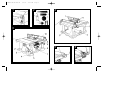
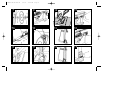
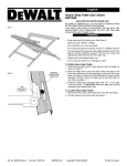
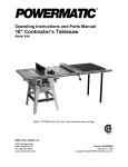
DW744-XE/387486-01
5/1/02
3:43 PM
Page 2
INSTRUCTION MANUAL
TABLE SAW
MODEL DW744
DW744-XE/387486-01
1
5/1/02
3:43 PM
Page 3
2
4
3
5
6
DW744-XE/387486-01
7
5/1/02
3:44 PM
Page 4
9
12
15
1
7A
10
13
16
8
11
14
17
DW744-XE/387486-01
5/1/02
3:44 PM
Page 6
18
21
24
19
22
25
20
23
DW744-XE/387486-01
5/1/02
3:44 PM
Page 5
15 Remove adjusting keys and wrenches. Always check that adjusting keys and
wrenches are removed from the tool before operating the tool.
16 Use appropriate tool. Do not force small tools or attachments to do the job of a
heavy-duty tool. The tool will do the job better and safer at the rate for which it is
intended. The use of any accessories or attachments other than the ones
recommended in this instruction manual may induce a risk of personal injury.
17 Do not abuse cord. Never carry the tool by its cord or pull it to disconnect from
the socket. Keep the cord away from heat, oil and sharp edges.
18 Maintain tools with care. Keep tools in good condition and clean for better and
safer performance. Follow the instructions for maintenance and changing
accessories. Inspect tool cords at regular intervals and, if damaged, have them
repaired by an authorised DEWALT Repair Agent. Inspect extension cords
periodically and replace them if damaged. Keep all controls dry, clean and free
from oil and grease.
19 Check damaged parts. Before using the tool, carefully check it for damage to
ensure it will operate properly and perform its intended function. Check for
misalignment and seizure of moving parts, breakage of parts and any other
conditions that may affect its operation. Have damaged guards or other defective
parts repaired or replaced as instructed. Do not use the tool if the switch is
defective. Have the switch replaced by an authorised DEWALT Repair Centre.
20 Have your tool repaired by an authorised DEWALT Repair Centre.
This power tool is in accordance with the relevant safety regulations.
To avoid danger, electric appliances must only be repaired by qualified
technicians.
Safety Instructions
When using power tools, always observe the safety regulations applicable in your
country to reduce the risk of fire, electric shock and personal injury. Read the following
safety instructions before attempting to operate this product. Keep these instructions in
a safe place!
General
1 Keep work area clean. Cluttered areas and benches can cause accidents.
2 Consider work area environment. Do not expose power tools to high humidity or
rain. Keep work area well lit. Do not use power tools in the presence of
flammable liquids or gases.
3 Guard against electric shock. Prevent body contact with earthed surfaces (e.g.
pipes, radiators, cookers and refrigerators).
4 Keep children away. Do not let children come into contact with the tool or
extension cord. Keep all people away from the work area.
5 Extension cords for outdoor use. When the tool is used outdoors, always use
extension cords intended for outdoor use and marked accordingly.
6 Store idle tools. When not in use, power tools must be stored in a dry place and
locked up securely, out of reach of children.
7 Dress properly. Do not wear loose clothing or jewellery. They can be caught in
moving parts. Preferably wear rubber gloves and non-slip footwear when
working outdoors. Wear protective hair covering to keep long hair out of the way.
8 Wear safety goggles. Also use a face or dust mask in case the operations
produce dust or flying particles.
9 Be aware of maximum sound pressure. Take appropriate measures for the
protection of hearing if the sound pressure of 85dB(A) is exceeded.
10 Secure workpiece. Use clamps or a vice to hold the workpiece. It is safer and it
frees both hands to operate the tool.
11 Do not overreach. Keep proper footing and balance at all times.
12 Avoid unintentional starting. Do not carry the plugged-in tool with a finger on the
switch. Be sure that the switch is released when plugging in.
13 Stay alert. Watch what you are doing. Use common sense. Do not operate the
tool when you are tired.
14 Disconnect tool. Shut off power and wait for the tool to come to a complete
standstill before leaving it unattended. Unplug the tool when not in use, before
servicing or changing accessories.
1
DW744-XE/387486-01
5/1/02
3:44 PM
Description Fig. 2
Figure 2 shows all the loose items and
hardware packed with the saw.
1. Rip fence
2. Blade (attached to saw base)
3. Arbor wrench and spindle wrench
(attached to saw base)
4. Blade guard
5. Throat plate
6. Mitre gauge
Description Fig. 3
1. Table
2. Screw-down holes
3. Mitre gauge
4. Mounting holes
5. ON-OFF switch
6. Rail lock lever
7. Bevel lock lever
8. Blade height adjustment wheel
9. Fine adjust knob
10. Rip scale indicator
Description Fig 4.
1. Blade guard
2. Work support extension (retracted)
3. Blade/wrench storage
4. Dust exhaust
5. Rip fence latch
6. Anti-kickback teeth
Description Fig. 5
1. Pin
2. Opening
Description Fig. 7
1. Spindle
2. Inner washer
3. Blade
4. Outer washer
5. Arbor nut
Description Fig 7A
1. Torx head bolts
2. Rear pivot bracket
3. 10mm hex bolts
Page 8
4. Rear pinion bearing assembly
5. Saw shown upside down for clarity
Description Fig. 8
1. Arbor wrench
Description Fig. 9
1. Rail lock lever
Description Fig. 10
1. Shims
2. Bolts
Description Fig. 11
1. Edge of splitter
Description Fig. 15
1. Fine adjust knob
Description Fig. 16
1. Screws
Description Fig. 17
1. Padlock insertion hole
2. ON-OFF Switch
Description Fig. 18
1. Belville washers
2. Nut
3. Gap
Description Fig. 19
1. Bevel stop cam
2. Bevel stop screw
3. Pointer screw
Description Fig. 21
1. Lock handle
2. Stop plate
3. Adjusting screw
4. Nut
Description Fig. 22
1. Push stick
Description Fig. 24
1. Dust access door
2. Hair pin cotters
3. Central dust cover scew
Description Fig. 25
1. Height adjustment threads
Additional Safety Rules for Table Saw
•
•
•
•
•
•
•
•
•
•
•
•
•
•
•
•
•
2
WARNING: For your own safety, do not operate your saw until it is completely
assembled and installed according to the instructions and until you have read and
understood the following :
All Safety Rules
Assembly Procedures
Operating Controls
Adjustment Procedures
Basic Operations
KEEP guards in place and in working order.
STABILITY. Make sure table saw is firmly mounted before use.
MINIMISE ACCIDENT POTENTIAL. Most accidents are caused by failure to
follow setup and operating instructions.
AVOID awkward hand positions, where a sudden slip could cause a hand to
move into a saw blade or other cutting tool. Never reach in back of, or around, the
cutting tool with either hand to hand down the workpiece. DO NOT PLACE
FINGERS OR HANDS IN THE PATH OF THE SAW BLADE.
NEVER reach under your machine when operating or make any adjustments
when it is running.
SHUT OFF the saw and disconnect the power cord when removing the table
insert, changing the cutting tool, removing or replacing the blade guard, or making
adjustments.
ALWAYS maintain control of the workpiece. DO NOT let go of the workpiece until
it is well clear of the cutting tool.
WHEN REMOVING short workpieces, or cleaning up around the table, be sure
the saw is in the OFF position and blade has stopped turning.
NEVER turn the saw ON before clearing the table of all tools, wood scraps, etc.,
except the workpiece and related feed or support devices for the operation
planned.
WHEN changing saw location, disconnect power.
USE extra caution when the guard assembly is removed for resawing, dadoing,
rabbeting, or moulding. Replace the guard as soon as that operation is
completed.
NEVER hold onto or touch the “free end” of the workpiece or a “free piece” that is
cut off, while power is ON and/or the saw blade is rotating.
DW744-XE/387486-01
•
•
•
•
•
•
5/1/02
3:44 PM
Page 9
IF YOU STALL OR JAM the saw blade in the workpiece, turn saw OFF, remove
the workpiece from the saw blade, and check to see if the saw blade is parallel to
the mitre gauge slots or grooves and if the splitter is in proper alignment with the
saw blade. If ripping at the time, check to see if the rip fence is parallel with the
saw blade. Readjust as indicated.
WARNING: Do not allow familiarity (gained from frequent use of your saw) to
replace following safety rules. Always remember that a careless fraction of a
second is sufficient to inflict severe injury.
MAKE SURE your fingers do not contact the terminals of the power cord when
installing or removing the plug to or from the line power source.
KICKBACKS - Kickbacks can cause serious injury. A kickback occurs when a
part of the workpiece binds between the saw blade and the rip fence, or other
fixed object, and rises from the table and is thrown toward the operator.
Kickbacks can be avoided by attention to the following conditions:
NEVER leave the saw turned ON and unattended.
NEVER attempt to remove gum or resin from a saw blade in motion. Ensure the
blade has completely stopped and the electrical power is turned OFF.
NEVER insert wedges between the blade flange and the blade to form what is
known as a wobble saw.
•
•
•
•
•
•
•
•
•
KICKBACKS - HOW TO AVOID THEM AND PROTECT
YOURSELF FROM POSSIBLE INJURY.
a) Be certain that the saw blade is parallel to the rip fence. Adjust fence if not
parallel.
b) Do not rip by applying the feed force to the section of the workpiece that will
become the cut-off (free) piece. Feed force when ripping should always be
applied between the saw blade and the fence...use a push stick for short work, 6”
(152 mm) wide or less. For less than 2” (52 mm) wide, you must use a special
fixture.
c) Keep saw blade guard, splitter and anti-kickback teeth in place and operating
properly. Keep teeth sharp. If teeth are not operational, return your unit to the
nearest DEWALT Service Centre for repair. The splitter must be in alignment with
the saw blade and the teeth must stop a kickback once it has started. Check
their action before ripping by pushing the wood under the anti-kickback teeth.
The teeth must prevent the wood from being pulled toward the front of the saw.
d) Plastic and composition (like hardboard) materials may be cut on your saw.
However, since these are usually quite hard and slippery, the anti-kickback teeth
may not stop a kickback. Therefore, be especially attentive to following proper
set up and cutting procedures for ripping.
e) Use saw blade guard and splitter for every operation for which it can be used,
•
including all through sawing.
DO NOT leave a long board (or other workpiece) unsupported so the spring of
the board causes it to shift on the table. Provide proper support for the
workpiece, based on its size and the type of operation to be performed. Hold the
work firmly against the fence and down against the table surface.
NEVER use a length stop on the free end of the workpiece when crosscutting.
Never hang onto or touch the free end of the workpiece when crosscutting, or a
free piece that is cut off when ripping while power is ON and/or the saw blade is
rotating. In short, the cut-off piece in any through sawing (cutting completely
through the workpiece) operation must never be confined – it must be allowed to
move away from saw blade.
IF YOUR SAW makes an unfamiliar noise or if it vibrates excessively, cease
operating immediately until the source has been located and the problem
corrected.
KEEP OUT of the line of saw blade. Stand to the side whenever possible.
USE a push-stick when required.
PAY particular attention to instructions on reducing risk of kickback.
DO NOT perform any operation free hand.
NEVER reach around, behind or over saw blade.
USE RECOMMENDED ACCESSORIES. The use of improper accessories
may cause risk of personal injury.
CAUTION: Some wood contains preservatives such as copper chromium
arsenate (CCA) which can be toxic. When cutting these materials extra care
should be taken to avoid inhalation and minimise skin contact.
USE A DUSTMASK and safety glasses when sawing. This saw is capable of
generating large amounts of sawdust.
SAVE THESE INSTRUCTIONS FOR FUTURE USE
Extension Cords
Use only extension cords that are approved by the country’s electrical authority.
Before using an extension cord, inspect it for loose or exposed wires, damaged
insulation and defective fittings. Replace the cord if necessary.
Replacement of the Supply Cord
If the supply cord is damaged, it must be replaced by the manufacturer or its service
agent or similarly qualified person in order to avoid a hazard.
3
DW744-XE/387486-01
5/1/02
3:44 PM
Page 12
ATTACHING/REPLACING THE BLADE
1. THE SAW MUST BE UNPLUGGED BEFORE YOU MAKE ANY
ADJUSTMENT TO THE BLADE.
2. Raise the saw blade arbor to its maximum height by turning the blade height
adjustment wheel clockwise.
3. Remove the arbor nut and flange from the saw arbor by turning
counterclockwise.
4. Place the saw blade on to the spindle making sure the teeth of the blade point
down at the front of the table. Assemble the washers and arbor nut to the spindle
and tighten arbor nut as far as possible by hand, making sure that the saw blade
is against the inner washer and the large washer diameters are against the
blade. Ensure the side of outer washer marked “Blade Side” is against the blade
(see Fig. 7). Ensure the spindle and washers are free from dust and debris.
5. To keep the spindle from rotating when tightening the arbor nut, use the openended spindle wrench to secure the spindle (see Fig 8).
6. Using the arbor wrench, tighten arbor nut by turning it clockwise (see Fig. 8).
7. NOTE: Different types of blades make different kerfs (width of cuts). Therefore, it
is necessary to check adjustment of rip fence pointer and blade guard splitter
when changing blades.
Specifications
Table Size:
Mitre Angle:
Bevel Angle:
Blade Size:
Max. Cut Depth:
Max. Cut Depth:
RPM, no load:
19 1/4” (489 mm) x 26 1/2” (673 mm)
30º L&R
0° to 45°L
10” (254 mm)
0° Bevel ..........3 1/8” (79 mm)
45° Bevel ..........2 1/4” (57 mm)
3650 rpm
Unpacking
Open the box and slide the saw out, as shown in Fig. 1.
Carefully unpack the table saw and all loose items from the carton. Examine all parts
to make sure that parts have not been damaged during shipping. If any parts are
missing or damaged, contact your dealer to replace them before attempting to
assemble the tool.
Examine Fig. 3 & 4 to become familiar with the saw and its various parts. The
following sections on assembly and adjustments will refer to these terms and you must
know what and where the parts are.
ASSEMBLY
ADJUST BLADE ALIGNMENT TO TABLE
1. THE SAW MUST BE UNPLUGGED BEFORE YOU MAKE ANY
ADJUSTMENT TO THE BLADE.
2. Place the unit in an upright position. Using a 10 mm socket, loosen rear pivot
bracket fasteners just enough to allow the bracket to move side-to-side. (Fig. 7a)
3. Adjust the bracket until the blade is parallel to the mitre gauge slot.
4. Tighten the rear pivot bracket fasteners to 7-8 lb-ft (9-11 Nm).
YOUR SAW SHOULD BE ASSEMBLED IN THE FOLLOWING ORDER:
1. Blade
2. Rip fence (NOTE: Adjust rip scale before proceeding. See “Adjusting Rip Scale”
pg 5).
3. Blade guard
4. Throat plate
Tools needed for assembly include a screwdriver and the wrenches included with
your saw.
ADJUSTING THE RIP SCALE
1. Unlock the rail lock lever (see Fig. 9).
2. Set the blade at 0° bevel and move the fence in until it touches the blade.
3. Lock the rail lock lever.
4. Loosen the rip scale pointer screws (see Fig. 16) and set the rip scale pointer to
read zero (0). Retighten the rip scale pointer screws. The rip scale reads
correctly only when the fence is mounted on the right side of the blade.
ASSEMBLING THE RIP FENCE
The rip fence can be installed on the left or right side of your table saw.
1. Locate the pin and opening on fence rails, as shown in Figure 5. Align the pin
with the slot and align the latch with the opening.
2. Secure the rip fence by snapping the latches onto the rails as shown in
Figure 6. Be sure to snap both latches in place.
ATTACHING THE BLADE GUARD
1. Raise the saw blade arbor to its maximum height by turning the blade height
adjustment wheel clockwise.
2. Loosen, but do not remove the two bolts shown in Fig. 10.
3. Align the slots on the blade guard with the bolts shown in Fig. 10. Insert the
4
DW744-XE/387486-01
5/1/02
3:44 PM
Page 13
1. Centre the saw on a square piece of 1/2” (12.7 mm) plywood. The plywood must
have a 15” (380 mm) by 20” (508 mm) opening to allow dust to escape.
2. Mark the positions of the four mounting holes in the base of the saw with a pencil.
3. Remove the saw and drill 1/4” (6.4 mm) holes in the places you have just
marked.
4. Position the saw over the four holes you drilled in the plywood and insert four 1/4”
(6.4 mm) machine screws FROM THE BOTTOM. Install washers and 1/4” (6.4
mm) nuts on the top. Tighten securely.
5. In order to prevent the screw heads from marring the surface to which you clamp
the saw, attach two strips of scrap wood to the bottom of the plywood base.
These strips can be attached with glue, or wood screws can be installed from the
top side as long as they don’t protrude through the bottom of the strip.
6. “C” clamp the plywood base to your workbench whenever you want to use
the saw.
CAUTION: Make sure table saw is firmly mounted before use.
blade guard as shown in Fig. 11, ensuring the bolts fit into the slots on the blade
guard. The top of the slots must rest on the bolts. The bottom edge of the splitter
should be aligned with the blade (see Fig. 10). If the blade and splitter are not
aligned, remove the blade guard and reinsert it after adjusting the shims. These
shims allow for precision alignment of the blade and splitter.
4. Retighten the bolts securely.
WARNING: Before connecting the table saw to the power source or operating
the saw, always inspect the guard and splitter for proper alignment and clearance
with the saw blade. Check alignment after each change of bevel angle.
When properly aligned, the splitter will be in line with the blade at both table top
level, and at the top of the blade. Check using the straight edge. With power
disconnected, operate the blade tilt and height adjustments through the extremes
of travel and insure the guard clears the blade in all operations and that the antikickback teeth are functioning.
Attaching the Throat plate
1. Align the throat plate as shown in Figure 12, and insert the tabs on the back of
the throat plate into the holes on the back of the table.
2. Press down on the front of the throat plate to snap it into place.
3. The throat plate includes four adjustment screws which raise or lower the throat
plate. When properly adjusted, the front of the throat plate should be flush or
slightly below the surface of the table top and secured in place. The rear of the
throat plate should be flush or slightly above the table top.
4. Turn the cam lock screw (Detail Fig. 12) clockwise 1/4 turn to lock the throat
plate in place.
Connecting Saw to Power Source
IMPORTANT: Before connecting saw to power source, make sure the switch is in the
OFF position.
Be sure your power supply agrees with the nameplate marking. A voltage decrease of
10 percent or more will cause a loss of power and overheating. All DEWALT tools are
factory tested. If this tool does not operate, check the power supply.
Rip Fence Operation
RAIL LOCK LEVER
The rail lock lever locks the rip fence rails in place, preventing their movement. To lock
the rail lock lever, push it down. To unlock the lever, pull it up (see Fig. 9).
NOTE: When ripping, always lock the rail lock lever.
CAUTION: The throat plate must be in place at all times.
Bench Mounting
TURN OFF AND UNPLUG TABLE SAW
The table saw must be mounted firmly. The mounting surface must have a 15” (380
mm) by 20” (508 mm) opening to allow dust to escape. Four holes are provided in the
tool’s feet for mounting. We strongly recommend that these holes be used to anchor
the table saw to your workbench or other stationary rigid frame. Alternately, to
enhance the saw’s portability, it can be mounted to a piece of wood that can be “C”
clamped to your work surface, stand or Workmate. The DEWALT DW7440 Table Saw
Stand is designed for use with this saw, and is available from your local DEWALT
dealer or service center.
WORK SUPPORT EXTENSION
Your table saw is equipped with a work support extension to support work that extends
beyond the saw table. To use the work support extension, rotate it as shown in Fig. 13.
When not in use, the work support extension retracts, as shown in Fig. 14.
NOTE: Retract the work support extension whenever working over the table.
FINE ADJUST KNOB
The fine adjust knob (shown in Fig. 15) allows smaller adjustments when setting the
fence. Before adjusting, be sure the rail lock lever is in its up, or unlocked, position.
CAUTION: Failure to securely mount the table saw to the work surface can
be hazardous.
5
DW744-XE/387486-01
5/1/02
3:44 PM
Page 14
FENCE PARALLEL ADJUSTMENT
1. Unlock rail lock lever.
2. Locate rear pinion bearing and loosen the two hex bolts just enough to allow
side-to-side movement.
3. Adjust fence parallel to blade.
4. Lock rail lock lever and check parallel alignment of the blade.
5. Tighten the 2 hex bolts that secure the rear pinion bearing assembly to the table.
NOTE: If there is not enough travel in the pinion bearing assembly to allow the fence
to be parallel to the blade, take the unit to an authorised service centre.
RIP SCALE POINTER
NOTE: The rip scale pointer will need to be readjusted whenever a thicker or thinner
blade is installed.
On-Off Switch
Lift the switch paddle up to turn your saw ON and push it down to turn your saw OFF.
A hole is provided in the switch for insertion of a padlock to lock the saw off (Fig. 17).
WARNING: Be sure switch is in the OFF position before plugging machine in.
Adjustments
RACK AND PINION MESH ADJUSTMENT
Proper adjustment of the rack and pinion mesh is done at the factory. If it should
become necessary to adjust the rack and pinion mesh, use the following procedure.
NOTE: All settings on your saw have been accurately adjusted at the factory.
RAIL LOCK ADJUSTMENT
1. Lock the rail lock lever (Fig. 9) by pushing down.
2. On the underside of your saw, tighten the nut shown in Figure 18. Adjust this nut
until the gap between the belville washers closes.
3. Once the springs are almost touching, loosen the nut 1/2 turn.
1. Turn the saw upside down and locate the front pinion bearing.
2. Using a narrow blade screw driver or #20 torx driver, access the screw through
the slot. Loosen the screw (counterclockwise) until the head touches the inside
of the bearing box.
3. Tighten the screw (clockwise) 3/4 of a turn.
4. Repeat procedure for rear pinion bearing
RIP SCALE ADJUSTMENT
See “ADJUSTING THE RIP SCALE” on page 5.
BEVEL STOP AND POINTER ADJUSTMENT
1. Raise the blade fully by rotating the blade height adjustment wheel clockwise until
it stops.
2. Unlock the bevel lock lever (Fig. 3) by pushing it up and to the right. Loosen the
bevel stop screw (Fig. 19).
3. Place a square flat against the table top and against the blade between teeth, as
shown in Fig. 20. Ensure the bevel lock lever is in its unlocked, or up, position.
4. using the bevel lock lever, adjust the bevel angle until it is flat against the square.
5. Tighten the bevel lock lever by pushing it down.
6. Turn the bevel stop cam until it firmly contacts the bearing block. Tighten the
bevel stop screw.
7. Check the bevel angle scale. If the pointer does not read 0°, loosen pointer
screw (see Fig. 19) and move the pointer so it reads correctly. Retighten the
pointer screw.
8. Repeat at 45°, but do not adjust pointer.
Saw Blades
THIS SAW IS INTENDED FOR THE USE OF BLADES 10” IN DIAMETER OR
SMALLER
1. The saw blade furnished with your new saw is a 10” (254mm) combination blade,
used for cross cutting (across the grain) and ripping (with the grain) through the
material. This blade will produce a good quality cut for most applications.
2. There are many types of blades available to do specific and special jobs such as
cross cut only, rip only, hollow ground, thin plywood, paneling, etc.
3. Use only saw blades designed for maximum safe operating speeds of 5,000
RPM or greater.
4. Saw blades should always be kept sharp. It is recommended that you locate a
reputable sharpening service to sharpen your blades when needed.
5. Never stack blades on top of one another to store. Place material such as
cardboard between them to keep the blades from coming in contact with one
another.
CAUTION: Abrasive wheels should not be used on this saw.
MITRE GAUGE ADJUSTMENT
Your mitre gauge features adjustable stops at 90° and 45° left and right. To adjust
these stops, loosen the lock nuts and tighten or loosen the three adjusting screws
against the stop plate (see Fig. 21).
Kickback
Kickback is a dangerous condition! It is caused by the workpiece binding against the
blade. The result is that the workpiece can move rapidly in a direction opposite to the
6
DW744-XE/387486-01
5/1/02
3:44 PM
Page 11
2. Bevel angle lock knob is tight.
3. If ripping, ensure rail lock lever is tight and fence is parallel to the blade.
4. If crosscutting, mitre gauge lever is tight.
5. Guard is in place and working properly.
6. Safety glasses are being worn.
7. The blade guard is properly attached and the anti-kickback teeth are functioning.
Failure to adhere to these common safety rules can greatly increase the likelihood
of injury.
feed direction. During kickback, the workpiece could be thrown back at the operator. It
can also drag the operator’s hand back into the blade if the operator’s hand is at the
rear of the blade. If kickback occurs, turn the saw OFF and verify the proper
functioning of the splitter, anti-kickback teeth and guards before resuming work.
CAUTION:
1. Always use the guard and make certain it is in good working order. The guard’s
splitter helps prevent binding and the anti-kickback teeth on each side of the
splitter minimise the possibility of kickback. Use extra caution until the workpiece
is through the splitter and has engaged anti-kickback teeth.
2. Do not saw warped, bowed or cupped wood. The workpiece must have one
straight, smooth side to go against the rip fence or mitre gauge. The workpiece
must sit flat on the table without rocking.
3. Do not cut “free hand”. Always use either the rip fence or the mitre gauge. Never
use both.
4. Use extra care when the guard assembly cannot be used (during dadoing or
moulding).
5. Support large workpieces carefully. Allowing them to sag or droop can cause
kickback.
Ripping
1. Lock the rip fence by pressing the rail lock lever down. Remove the mitre gauge.
2. Raise the blade so it is about 1/8” (3.2 mm) higher than the top of the workpiece.
3. Hold the workpiece flat on the table and against the fence. Keep the workpiece
about 1” (25.4 mm) away from the blade.
CAUTION: The workpiece must have a straight edge against he fence and
must not be warped, twisted or bowed. Keep both hands away from the blade
and away from the path of the blade.
4. Turn the saw on and allow the blade to come up to speed. Both hands can be
used in starting the cut. When there is approximately twelve (12) inches (305
mm) left to be ripped use only one hand, with your thumb pushing the material,
your index and second finger holding the material down and your other fingers
hooked over the fence. Always keep your thumb along side your first two fingers
and near the fence.
5. Keeping the workpiece against the table and fence, slowly feed the workpiece
rearward all the way through the saw blade. Continue pushing the workpiece
until it is clear of the guard and it falls off the rear of the table. Do not overload the
motor.
6. Never try to pull the workpiece back with the blade turning. Turn the switch off,
allow the blade to stop, raise the anti-kickback teeth on each side of the splitter if
necessary and slide the workpiece out.
7. When sawing a long piece of material or a panel, always use a work support. A
sawhorse, rollers, or out feed assembly provides adequate support for this
purpose. The work support must be at the same height as the saw table.
CAUTION: Never push or hold onto the “free” or “cut off” side of the workpiece.
Operation
Plain sawing includes ripping and cross cutting, plus a few other standard operations of
fundamental nature. The following methods feature safety. As with all power tools
respecting the tool, using caution and following safe practices will considerably lessen
the possibility of personal injury. However, if normal safety precautions are overlooked
or completely ignored, personal injury to the operator can result. Read and follow all
warnings indicated on the saw. Through sawing is any operation which renders the
material into two separate pieces. Observe the safety rules included in this manual.
THIS SAW IS NOT INTENDED FOR CUTTING METAL.
Operating Instructions
There are two basic types of cuts: ripping and crosscutting. In general, cutting with the
grain is ripping and across the grain is crosscutting. However, with man made
materials this distinction is somewhat difficult to make. Therefore, cutting a piece of
wood to a different width is ripping and cutting across the short dimension is
crosscutting. Neither ripping or crosscutting may be done safely freehand! Ripping
requires the use of the rip fence and crosscutting uses the mitre gauge.
Bevel Ripping
CAUTION: Before using the saw each and every time verify the following:
1. Blade is tight.
This operation is the same as ripping except the bevel angle is set to an angle other
than zero (0) degrees.
7
DW744-XE/387486-01
5/1/02
3:44 PM
Page 10
WARNING: Before connecting the table saw to the power source or operating the
saw, always inspect the guard and splitter for proper alignment and clearance with saw
blade. Check alignment after each change of bevel angle.
Mitreing
This operation is the same as crosscutting except the mitre gauge is locked at an
angle other than 0°. Hold the workpiece FIRMLY against the mitre gauge and feed the
workpiece slowly into the blade (to prevent the workpiece from moving). See Fig. 23.
Ripping Small Pieces
MITRE GAUGE OPERATION
To set your mitre gauge, loosen the lock handle and move the mitre gauge to the
desired angle. The mitre gauge has set stops and 90° and 45° left and right. To rotate
the mitre gauge beyond these stops, flip the stop plate up, as shown in Fig. 21.
It is unsafe to rip small pieces. It is not safe to put your hands close to the blade.
Instead, rip a large piece to obtain the desired piece. When a small width is to be
ripped and the hand cannot be safely put between the blade and the rip fence, use one
or more push sticks. Use them to hold the workpiece against the table and fence, and
push the workpiece against the table and fence, and push the workpiece fully past the
blade. See Fig. 22.
Compound Mitreing
This is a combination of bevel crosscutting and mitreing. Follow the instruction for both
bevel crosscutting and mitreing.
Crosscutting
1. Remove the rip fence and place the mitre gauge in the desired slot.
2. Adjust the blade height so that the blade is about 1/8 (3.2 mm) higher than the
top of the workpiece.
3. Hold the workpiece firmly against the mitre gauge with the path of the blade in
line with the desired cut location. Keep the workpiece an inch or so in front of the
blade. KEEP BOTH HANDS AWAY FROM THE BLADE AND THE PATH OF
THE BLADE.
4. Start the saw motor and allow the blade to come up to speed.
5. While using both hands to keep the workpiece against the face of the mitre
gauge, and holding the workpiece flat against the table, slowly push the
workpiece through the blade. See Fig. 23.
6. Never try to pull the workpiece with the blade turning. Turn the switch OFF, allow
the blade to stop, and carefully slide the workpiece out.
CAUTION: Never touch or hold onto the “free” or “cut off” end of the workpiece.
Dado Cutting
CAUTION: Do not attempt to stack dado blades thicker than 13/16”
(20 mm). Do not use dado blades larger than 8” (200 mm) diameter. Since
dado cuts are not through cuts, the cuts must be performed with the blade
guard removed. To remove the blade guard, loosen the two bolts shown in Fig.
10 and remove the guard assembly.
When using the dado, (sold as an accessory) the special dado insert (also sold as an
accessory) must be used.
Any time a cut is required that is considerably wider than the saw kerf, a dado is used.
A dado cut is commonly used to add support and line up a shelf for a cabinet,
bookcase or some such project. When using the dado, the guard must be removed.
Use EXTREME care when using the dado without the guard. If a deep cut is required
use several successive passes rather than attempting to make it with one pass.
Maximum dado width on this saw is 13/16” (20 mm). DO NOT USE WIDER
COMBINATIONS.
Bevel Crosscutting
CAUTION: Always check dado blade clearance before plugging in the saw.
Be sure to place the guard back in position and check adjustments when the dado cuts
are complete.
This operation is the same as crosscutting except that the bevel angle is set to an
angle other than 0°.
WARNING: Before connecting the table saw to the power source or operating the
saw, always inspect the guard and splitter for proper alignment and clearance with saw
blade. Check alignment after each change of bevel angle.
8
DW744-XE/387486-01
5/1/02
3:44 PM
Page 7
Dust Collection
DEWALT After-Sales Service
Your table saw is equipped with a dust shroud and dust collection port. For best
results, connect a vacuum to the port at the rear of the saw. If the saw is operated
without a vacuum attached, most of the dust will be blown out of the dust collection
port. However, some dust will fall inside the base. If the saw is used on a table or
other surface without an opening on the bottom, clean out the base and accumulated
saw dust after each cut. After extended use, the saw’s dust collection system may
become clogged. To clear the dust collection system:
All DEWALT power tools are thoroughly tested before leaving the factory. However, if
the power tool needs repair, please contact your dealer or take it to your nearest
DEWALT Service Centre.
Guarantee
Full One Year Warranty
DEWALT heavy duty industrial tools are warranted for one year from date of purchase.
We will repair, without charge, any defects due to faulty materials or workmanship.
Arrangements have been made with the Industrial Tool Division of Black & Decker to
provide warranty repairs for DEWALT tools. Please return the complete unit,
transportation prepaid, to any DEWALT Service Centre, Black & Decker Service
Centre or any authorised service station. This warranty does not apply to:
a) Unplug the saw.
b) Turn the saw on its side, so the bottom, open part of the unit is accessible.
c) Open the dust access door shown in Fig. 24 by removing the two hair pin cotters
or the central retaining screw on the dust cover. Clean out the excess dust, and
re-secure the access door with the hair pin cotters or the central dust cover
screw.
When cutting wet wood without a vacuum or when cutting with a dado blade,
removing the dust access door may be helpful in preventing clogs.
•
•
•
Lubrication
Accessories
Damage caused where repairs have been made or attempted by others
Damage due to misuse, neglect, wear and tear, alteration or modification.
Free One Year Service Contract
1. All motor bearings are permanently lubricated at the factory and no additional
lubrication is needed.
2. The height adjustment screw may require periodic cleaning and lubrication. if
you have difficulty raising or lowering the blade:
a) Unplug the saw.
b) Turn the saw on its side, so the bottom, open part of the unit is accessible.
c) Clean and lubricate the height adjustment screws threads on the underside of
your saw with general purpose grease, as shown in Fig. 25.
In addition to a full one year warranty, every DEWALT tool is backed with a Free One
Year Service Contract. We will provide free labour on all repair and preventative
maintenance during the first year after purchase. Proof of purchase date is required.
30 Day No Risk Satisfaction Guarantee
If you are not completely satisfied with the performance of your DEWALT heavy duty
industrial tool, simply return it to the participating seller within 30 days. Proof of
purchase date is required.
Unwanted Tools and the environment
Cleaning
Take your old tool to an authorised DEWALT Repair Agent where it will be disposed of
in an environmentally safe way.
Use only mild soap and damp cloth to clean the tool. Never let any liquid get inside the
tool; never immerse any part of the tool into a liquid. Never use solvents to clean saw
or guard components.
NOTES:
• DEWALT reserves the right to change or upgrade the product specifications or
standard equipment at any time without notice.
• Standard equipment and accessories may vary by country.
• Product specifications may differ by country.
• Complete product range may not be available in all countries. See your local
DEWALT dealer for range availability.
Important
To assure product SAFETY and RELIABILITY, repairs, maintenance and adjusting
(including brush inspection and replacement) should be performed by authorised
service centres or other qualified service organisations, always using identical
replacement parts.
9
DW744-XE/387486-01
5/1/02
3:42 PM
Page 1
NOTE: THIS INSTRUCTION MANUAL IS APPLICABLE FOR THE FOLLOWING SUB-CODES: -XE
DEWALT INDUSTRIAL TOOL COMPANY
COPYRIGHT © 1998, 1999
Form#
PART
NO:387486-01
569544-00