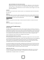
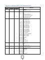
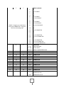
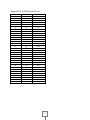
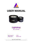
1
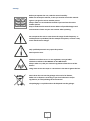
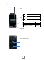
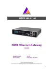
USER MANUAL
.
Wireless DMX Receiver/Transmitter
(ART3)
Manual Version:
Release Date:
3.8.18
July 11, 2013
Astera LED Technology GmbH
Address : Nahestrasse 68-70, 55593 Rüdesheim an der Nahe, Germany Tel.: +49(0)6536-355361 Email: [email protected]
Index
Contents
Index ........................................................................................................................................................ 2
Safety....................................................................................................................................................... 3
Introduction ............................................................................................................................................ 4
Overview ............................................................................................................................................. 4
Operation Modes ................................................................................................................................ 5
Navigation through the menu ............................................................................................................. 5
Operation ................................................................................................................................................ 6
DMX Transmitter Mode ...................................................................................................................... 6
RC Transmitter Mode .......................................................................................................................... 9
DMX Receiver Mode ......................................................................................................................... 11
RC Receiver Mode ............................................................................................................................. 12
Control Lamps ................................................................................................................................... 14
Setup ................................................................................................................................................. 15
Technical Specifications ........................................................................................................................ 16
Appendix 1: DMX tab for ART3 in RC transmitter mode ....................................................................... 17
Appendix 2: DMX Output Chart ............................................................................................................ 19
2
Safety
Before you operate the unit, read this manual carefully.
Make sure to keep the manual, in case you need to consult this manual
again or you give the unit to another person.
Always make sure to include this manual if you hand out the unit to
another person.
Keep in mind that this manual cannot address all possible dangers and
environments. Please use your own caution when operating.
Do not operate the unit in areas where the usage of radio frequency or
mobile phones is prohibited, like for example in airplanes, or when it may
cause interference or danger.
Only qualified personnel may repair this product.
Don't open the case.
This device conforms to CE -or- FCC regulation, see type label!
This device radiates in the 868 MHz or 915 MHz bands.
Always make sure, that your national regulations allow the use of this
device!
Using a FCC version in Europe or a CE version in the USA is against the law.
Don't throw the unit into the garbage at the end of its lifetime.
Make sure to dispose is according to your local ordinances and/or
regulations, to avoid polluting the environment!
The packaging is recyclable and can be disposed into the garbage.
3
Introduction
Overview
antenna
Receiving
Transmitting
display
settings are stored in memory
sync between units is active
statusLED
red color
ready to transmit
XLR = input
red flickering
transmitting
XLR = input
green color
ready to receive
XLR = output
green flickering
receiving
XLR = output
power on/off
AC power input (110-240V)
DMX socket (works as in- & output)
DMX socket (works as in- & output
4
Operation Modes
The ART3 is a very versatile product and can be used to send or receive data. It can work with
wireless Astera lights or controllers as well as with conventional DMX fixtures from other companies.
Also, it can be used as an emergency remote control in case you forgot the ARC2 or ARC6.
Because of the many settings and purposes of the ART3 it is important to carefully check the desired
mode before starting to use it. Here is how you can find out:
Navigation through the menu
The navigation panel with its display and 4 buttons is used to navigate between the Operation Modes
and to change settings.
When the display shows the name of one of the 5 operation modes in capital letters or SETUP you
are in the top level navigation. Use the + and – buttons to navigate between the operation modes.
When in one of the operation modes press Enter and then use the + and – buttons to reach its
settings. Press Enter to confirm and Back to abort.
5
Operation
DMX Transmitter Mode
Introduction
The DMX Transmitter mode is for customers that want to send DMX data to Astera lamps and/or to
other ART3s that are set to DMX receiver mode. The DMX Transmitter simply transmits the DMX
protocol from a standard DMX controller such as Martin Lightjockey, GrandMA and computer-based
systems over the air to Astera lights and ART3s that are set to DMX Receiver. For this, the DMX Data
gets compressed.
Characteristics
-
Works straight out of the box, all you have to set is the DMX addresses of the lights
-
Establishes a constant link to the lights/ART3s it controls. If the link is interrupted the
lights/ART3 wont react correctly
-
Range: 50-100m
-
Transmits a limited amount of data, to get better results use several with different radio pins
at the same time (see bottom of page 7). The more channels you transmit the lower the
refresh rate.
Setup of ART3
When you buy a new ART3 or when you Factory Reset the ART3 it is already set into DMX
Transmitter mode. All you have to do is connect it to an AC power socket and to your DMX Controller
and it will automatically start transmitting as soon as it receives DMX data which is indicated by a
flickering blue light and the display showing TRANSMITTING...
While in the DMX Transmitter mode you can press the Enter key then + key to select the minimum
and maximum addresses of this ART3, this is useful when using several ART3s at the same time. Also,
you can find information about the ART3 by pressing the enter key. Press the menu button to go
back.
Setup of lamps
With the ARC2 or inside the menu of lights with keyfoil and buttons you can set the following:
DMX Address:
New lights or lights that have been factory reset are set to DMX address. You can set other DMX
addresses for any wireless Astera light:
Lights without display and on/off button (AL1, AL3, AL7-L):
Take the ART3 press the – button until you see Setup and confirm with Enter. Choose DMX
Setup > DMX Address, choose the desired address and press Enter. All lamps in range will
start blinking white once a second. Press the on/off buttons of the lamps you want to set to
this address. Alternatively you can use the ARC2 to send addresses to lights, the ARC2 Quick
Start Guide explains this process well.
6
Lights with display and 5 buttons (AL6, AL7-W):
Hold the menu button for 3 seconds, select DMX Setup > DMX Setup > confirm with Enter >
select an address > confirm with Enter. For setting a larger number of lights, set addresses
with ART3 or ARC2 as described above but confirm the address with the light’s Enter button
(not the on/off button).
Channels:
Sets the amount of channels that is used to control 1 unit. 1 RGB channel means that all LEDs have
the same color.
DMX Tab:
Several DMX tables can be chosen. When sending DMX channels from an ART3 in DMX transmitter
mode each Astera light behaves different depending on its amount of pixels. Refer to www.asteraled.com/DMXtab/ for pdf’s that show the DMX tables.
Strobe:
Defines if each pixel has its own strobe, if 1 channel controls all strobes or if strobe is turned off.
DMX Fail:
Defines what happens if the DMX signal is lost.
Limitations and Troubleshooting
Very low range:
The DMX Transmitter Mode is known to have a lower range than the RC Transmitter. To boost the
range a bit you can move the ART3, even a meter can make a large difference. The best result would
be achieved if it would be in the very center of the room if this is not possible move it a bit up and a
bit into the room, don’t get it tied up in metal structures such as trussing. To increase the range you
can use additional ART3s (see below) so that each ART3 transmits less data. Having a directed
antenna would help in some situations but is illegal in many countries.
Lights sometimes get stuck for 1-2 seconds:
If the DMX signal gets interrupted due to lack of bandwidth some lights will not receive any data for
1-2 seconds and not display the next frame. To get a more stable transmission you can use additional
ART3s (see below) so that each ART3 transmits less channels. Also, having slow fades between
scenes requires less bandwidth than abrupt changes and as long as you only change the value of
some DMX channels and not all channels you should not have this problem.
If you have the impression that your ART3 is sending too many channels you can test this. Press the
Enter button and change the maximum address as described above from 512 to 100. That way you
only transmit 100 channels instead of 512. Have a look if the transmission is more efficient now. If
yes, use additional ART3s to transmit channels the other channels.
Lamps don’t react at all:
If the lamps don’t react and the display shows NO DMX SIGNAL the DMX cable is not connected
correctly or the DMX Controller has a problem. If the lamps don’t react and the display shows
TRANSMITTING...the DMX Controller is set to Blackout.
7
Summary:
There are several ways to increase the performance of the ART3. It is important to know the ART3’s
characteristics and sometimes adjust a lighting installation. If you transfer fewer data the
performance will be better. For video content we recommend no more than 100 channels per ART3
for slow ambient installations 200 channels per ART3.
If all the above info is not enough you can switch to the RC Transmitter mode (see page 9), which has
a much higher range and works more stable.
Using several ART3s
When using more than 100 DMX channels and experiencing problems you can use several ART3s at
the same time so each one only transmits a part of the data. To make sure they send on different
frequencies you need to give each ART3 an individual Radio Pin (e.g. 0000, 0001, 0002).
Set the Radio Pin of an ART3:
Go to Setup > Radio Pin > Set Pin > use the + and – buttons to set a pin and confirm with Enter.
Set the Radio Pin of a light:
Put the light into blue-mode by holding its power button until it starts blinking rapidly in blue color.
Take the ART3, which you want to use to control these lights, go to Setup > Radio Pin > Pair with
Lamps. The lamps that were in blue-mode should exit the blue mode which means that they were set
to the new Radio Pin.
Lights with display and 5 buttons offer the chance to check or set the Radio Pin by holding the menu
button for 3 seconds > Info > Radio Pin > press Enter and select a pin with the + and – buttons and
confirm with Enter. Alternatively you can use the ARC2 to send addresses to lights, the ARC2 Quick
Start Guide explains this process well.
When using several ART3s with individual Radio Pins, make sure to have enough space between the
ART3s so that they won’t interfere with each other. You can use a different DMX universe for each
ART3 or you can use several ART3s in the same universe, for example by transmitting 150 channels
through one ART3, 150 channels through another and the remaining 212 channels through a third
ART3. In this case, set the Minimum and Maximum Address of each ART3 to make sure he only sends
these channels. When in the DMX Transmitter Mode, press Enter > Select Min or Max address and
choose addresses.
8
RC Transmitter Mode
Introduction
In the RC Transmitter mode the ART3 controls Wireless Astera lamps, the same way an ARC2 or ARC6
remote control would do but the parameters are set by a DMX control table. You can send and
customize basic running and fading effects and send them to individual lights or groups of lights.
The basic advantages of this operation mode are a higher range and that data is only sent during
changes. With only 20 DMX channels you can control a whole setup of lights and/or ART3s.
Characteristics
-
20 channels are enough to control an unlimited amount of lights
No constant link, only changes get transmitted. The lights operate independently once they
received a command
Range: 100-300m
User should be familiar with the Astera control system
Setup of ART3
Set the ART3 to RC Transmitter Mode (see page 5). As soon as it receives a signal the display shows
TRANSMITTING.. and the status LED starts blinking in green color.
When in the RC Transmitter mode press the Enter button to change the following values:
RC DMX Address:
Chooses the ART3's input DMX address from 1-511. The ART3 will act as a normal DMX fixture. The
remote control functions are mapped to DMX channels see page 17.
DMX Tab:
Three DMX tables that control the lamps can be chosen. Each one has a predefined set of DMX
channels and their effects on the lamps. A table showing the DMX tables for each tab can be found
on page Error! Bookmark not defined..
While the DMX Tabs STANDARD and EXTENDED offer the same possibilities as the ARC2 remote
control just that you input the values directly at a DMX light controller the DMX Tab
SIMPLE RGB offers an easy way to control colors of 4 pixels with 3 DMX channels for each pixel.
Simple RGB is the default value of DMX Tab.
Setup of lights
The lights do not have to be set at all and will work straight out of the box as soon as they receive
data from an ART3 in RC Transmitter mode. For more complex setups you can define different groups
for some lights or create Sets of lights. To address a single light choose the Extended DMX Tab (see
above) and create a Set with only the one light you want to address individually.
9
To assign lights to Groups and build Sets this we recommend to use the ARC2, the ARC2 Quick Start
Guide explains this process well. Alternatively you can take an ART3, go to Setup > Create a Set or
respectively to Setup > Remote Setup > Remote Group. Lights with display and 5 buttons also offer
the chance to change their group. To do this hold the menu button for 3 seconds > choose Auto
Settings > Group > select a group with the + and – buttons and confirm with Enter.
Troubleshoot
Lights don’t react and display says NO DMX SIGNAL:
The DMX cable is not connected to the ART3 or to the DMX controller.
Lights don’t react and display says RECEIVING DMX:
The DMX cable is connected but the ART3 does not receive any data. The DMX controller might be
set to blackout or might have problems.
Lights react incorrectly:
Most likely the DMX addresses of the light or the DMX controller are not set correctly.
10
DMX Receiver Mode
Introduction
An ART3 in DMX Receiver Mode enables conventional DMX fixtures to be controlled by wireless
DMX. It transmits the DMX protocol that is sent from another ART3 (in DMX Transmitter mode) over
the air so that the lights can be controlled in the same way as if wired by DMX cable.
Characteristics
-
Very easy to set up, just like an invisible wire.
Just set the DMX address for each fixture
Setup of ART3
Set the ART3 to DMX Receiver Mode (see page 5). As soon as the ART3 in DMX Receiver Mode
receives a wireless DMX signal, the power-LED start flickering red, the display shows LINK OK and the
XLR connector outputs DMX data. If the signal is lost, the display shows NO LINK and the transmission
stops.
Several additional functions can be set inside the ART3. To get to these functions, simply press the
Enter button while in DMX Transmitter mode and use the + and – buttons to switch between the
functions.
DMX Failure
When in the DMX Receiver mode you can also set a value for DMX Failure in case the DMX signal is
interrupted and the ART3 does not receive any DMX data. Four values are possible:
Hold:
If the DMX reception times out, the output keeps unchanged and the
last received DMX frame is displayed.
Emergency Light:
If the DMX reception times out, the light turns white.
Blackout:
If the DMX reception times out, all light turns black.
Auto Program:
If the DMX reception times out the ART3 displays any of the 20
preprogrammed programs.
Setup of third-party LED fixtures
Set DMX addresses of the fixtures that are connected to the ART3 just like you would set them if they
were connected by DMX cable. Refer to the fixture’s user manual about how to set addresses.
11
RC Receiver Mode
Introduction
An ART3 in RC Receiver Mode enables conventional DMX fixtures to be controlled by the Astera
Remote Controls. That enables customers to control battery-powered Astera lights together with
conventional DMX fixtures.
Characteristics
-
Receives data from ARC2 and ARC6 and ART3 in RC Transmitter Mode
Can connect up to 32 third-party fixtures
Can be used as standalone controller to control the connected fixtures
Setup of ART3
Set the ART3 to DMX Receiver Mode (see page 5). Daisy-chain the third-party fixtures which you
want to control to the ART3. The ART3 outputs 32 pixels so it can control 32 fixtures with 1 pixel each
or fewer multi-pixel fixtures. If you have more than 32 pixels you can use several ART3s that are set
to RC Receiver mode.
It is important to set the exact number of pixels that are connected to the ART3 so that effects get
displayed correctly. While in RC Receiver mode press the Enter button twice and use the + and –
buttons to select the number of pixels. Confirm with Enter.
As soon as the ART3 receives a new program the display will show this program which confirms that
it is receiving data.
Users that are familiar with the Astera system can change or look up a number of other settings such
as defining Group or Set number, Program or Colors of the ART3. While in RC Transmitter mode,
press the Enter button and use the + and – buttons to choose among the settings. Confirm with Enter
and press the Back button to abort.
Apart from Auto Pixels a range of values can be set to control the connected third-party lamps
directly from the ART3 without the need for an ARC2 remote control. Refer to the ARC2 manual for
an explanation about these features.
Setup of third-party LED fixtures
The connected fixtures need to be set to 3-channel DMX (RGB). Alternatively they can be set to 6channel DMX where the first 3 channels are for RGB and the following 6-channels can be set to zero.
4-channel DMX, 7-channel DMX etc. are not supported. To check how to set your fixture to 3-channel
DMX, please refer to its manual.
If you want to use more than 1 pixel, set the fixtures accordingly: pixel 2 should be DMX address 004,
pixel 3 should be DMX address 007 etc. up to address 94. For fixtures that use 6-channel DMX (see
paragraph above) the ART3 outputs data from Channels 97 onwards: pixel 1 = channel 97, pixel 2 =
channel 103, pixel 3 = 109. Please refer to DMX Output Chart on page 19.
12
Troubleshoot
The connected fixtures do not display anything:
As soon as the ART3 receives a new program the display will show this program which confirms that
it is receiving data. If you see that the program names on the display are changing the link to the
remote control is ok and there must be a problem with the connected fixture. Try to connect another
fixture.
Fixtures display the effects incorrectly:
Make sure you have set all connected fixtures to 3-channel DMX and make sure you have selected
the correct amount of connected pixels.
Fixtures does not support 3-channel or 6-channel DMX:
3-channel DMX (RGB) is the most common DMX protocol and is supported by most DMX fixtures. If
your fixture does not support 3-channel DMX or 6-channel DMX (with channel 4,5,6 set to zero),
please use another DMX fixture.
13
Control Lamps
Introduction
The ART3 can be used as a remote control, providing basic functionality of the ARC2 and ARC6
remote controls. Although the other remotes are easier to use and have more buttons ART3 can do
most of the ARC2 functions in case no other remote is available.
Characteristics
-
Can control an unlimited amount of lights
This operation mode does not input or output the DMX protocol
Requires basic use of the Astera control system
Settings
Set the ART3 to Control Lamps (see page 5) to use it as a remote control.
The following settings can be adjusted with the ART3 in Control Lamps mode. Confirm with Enter,
abort with the Return button.
Target Lamps:
Offers a range of possibilities to target several lights of all the lamps in range.
It is possible to target lights by type, serial number, group, set number or by
tapping several lamps
Program:
Plays one of 20 predefined programs that can be customized with colors,
intensity, power scheme, speed, fade, directions, etc.
Intensity:
Sets the brightness of the lamps.
Power Scheme:
Three different power schemes can be set to optimize the light for highbrightness, maximum runtime or normal playback.
Speed:
Sets the speed with which a program is played.
Fade:
Sets the fading transitions between different colors from hard transition to
smooth transitions.
Direction:
Sets the direction of a program and whether it loops continuously or is
played only once.
Strobo Speed:
Starts the strobe-light and defines the frequency of the strobe effect
Random Mode:
Switches to a random mode on which displays programs at a changing rate.
Random Fade:
Defines the random fade
Use Random Cols:
Uses random colors to display programs
Color 1:
Sets color 1 that is used to display programs
Color 2:
Sets color 2 that is used to display programs
Color 3:
Sets color 3 that is used to display programs
Color 4:
Sets color 4 that is used to display programs
Info:
Gives you information about software and RF link
14
Setup
Introduction
The Setup is used to set up the lights, rather than the ART3 itself. It offers advanced settings that can
be used before or after an event like factory reset, forming groups of lamps, setting a light’s DMX
address etc. To get to Setup, see bottom of page 5.
Settings
The following settings can be adjusted. After changing the settings all lights in range will blink in
white light once a second. Press the Enter or on/off button of the lights to confirm on which lamps
you want to execute this setting. Here is a hierarchical tree of the setting along with a short
description. For a complete list that explains each setting, please refer to the ARC2 manual.
Create a Set:
A set is a cluster of lamps with fixed positions that can be targeted at the same time.
Create a Chain: Use a chain to stretch effects over several Sets
DMX Setup:
Send a number of DMX settings to lamps that do not have a display
DMX Address: Sets the DMX address of the desired light
DMX Pixels: Sets how many pixels a light has (all, one or reduced pixels)
DMX Tab:
Several different DMX tables can be chosen to select what channels are used to
control the lights (RGB S RGB S, RGB RGB S S, Effect Mode Fix, Effect Mode RGB)
Strobe:
Sets how many channels are used to control each pixel’s strobe
DMX Failure: Sets the behavior of the light in case of an interrupted DMX signal.
Remote Setup: Send a number of settings to lamps that do not have a display
Remote Group:Defines the group in which a lamp is
Input Select: Defines which signal a light listens to (XLR, wireless DMX, remote, standalone)
AC Failure:
Sets the behavior of battery powered lights in case of power failure
Manual Wht Calib: Allows you to calibrate the RGB levels to match other white LED lights
Test Radio:
A test to check the distance of lights and ART3 to see if the antenna is defect
Radio Pin:
The Radio Pin sets the frequency and makes it possible to operate several lights and
controllers without them influencing each other. Controllers and lights must have the
same radio pin in order to work with each other.
Factory Reset: Factory Reset puts the ART3 or a lamp into its original state and deletes all settings.
The only setting that is not influenced by Factory Reset is the Radio Pin
15
Technical Specifications
General
Temperature (operation)
5 °C – 40 °C
Temperature (transport)
-25 °C – 55 °C (70 °C for 24h)
Altitude
up to 2000 m above sea level
Environment
indoor
Input Power
110-240V, 50-60Hz AC
Radio Frequency
RF coverage
50m up to 300m
Frequency
Europe: 868.000 MHz – 869.750 MHz
US: 902MHz – 928 MHz
16
Appendix 1: DMX tab for ART3 in RC transmitter mode
SIMPLE
MODE
STANDARD
1
EXTENDED
1
VALUE
FUNCTION
0-255
2
2
0-3
4
5
6
7-255
3
3
0-6
7-14
15-22
23-30
31-38
39-46
47-54
55-62
63-70
71-78
79-86
87-94
95-102
103-110
111-118
119-126
127-134
135-142
143-150
151-158
4
4
0
1-255
5
5
0-255
6
6
0-63
64-127
128-190
191-255
17
DIMMER
Brightness of 0%-100%
STROBE
OFF
RANDOM STROBE FAST
RANDOM STROBE MEDIUM
RANDOM STROBE SLOW
STROBE SLOW->FAST
PROGRAM
ONE COLOR STATIC
TWO COLOR STATIC
THREE COLOR STATIC
FOUR COLOR STATIC
ONE COLOR FADE
TWO COLOR FADE
THREE COLOR FADE
FOUR COLOR FADE
SIMPLE RUNNING
DOUBLE RUNNING
TWO COL RUNNING
FLAG RUNNING
DOUBLE FLAG RUNNING
SPIRAL 4 COLORS
SPIRAL 2 COLORS
RAINBOW
FIRE
ROTOR
ROTOR SPLIT 2
ROTOR SPLIT 4
SPEED
STOP
SPEED SLOW->FAST
FADE
0%-100% of step time
DIRECTION
LOOP+FFW
FFW
REW
LOOP+REW
7
7
SINGLE = Programs run separate on
each group CONNECTED = Programs
span over selected groups
8
1
2
3
4
5
6
7
8
9
10
11
12
9
10
11
12
13
14
15
16
17
18
19
20
SEND TO GROUPS
G1
G1 G2 SINGLE
G2
G3
G2 G3 SINGLE
G1 G2 G3 SINGLE
G4
G3 G4 SINGLE
G2 G3 G4 SINGLE
G1 G2 G3 G4 SINGLE
1
3
2
4
6
7
8
12
14
15
130
132
131
133
135
136
137
141
143
144
8
9
10
11
12
13
14
15
16
17
18
19
20
21
0-10
11-245
246-255
0-255
0-255
0-255
0-255
0-255
0-255
0-255
0-255
0-255
0-255
0-255
0-255
0
1-255
18
G1
G1 G2 CONNECTED
G2
G3
G2 G3 CONNECTED
G1 G2 G3 CONNECTED
G4
G3 G4 CONNECTED
G2 G3 G4 CONNECTED
G1 G2 G3 G4 CONNECTED
SEND MODE
SEND ON MODIFY
DO NOT SEND
SEND ALL PARAMETERS NOW
COLOR 1 RED
COLOR 1 GREEN
COLOR 1 BLUE
COLOR 2 RED
COLOR 2 GREEN
COLOR 2 BLUE
COLOR 3 RED
COLOR 3 GREEN
COLOR 3 BLUE
COLOR 4 RED
COLOR 4 GREEN
COLOR 4 BLUE
SET ADDRESS
ADDRESS ALL SETS
ADDRESS SET #1-255
Appendix 2: DMX Output Chart
Pixel #
1
2
3
4
5
6
7
8
9
10
11
12
13
14
15
16
17
18
19
20
21
22
23
24
25
26
27
28
29
30
31
32
Address RGB
1
4
7
10
13
16
19
22
25
28
31
34
37
40
43
46
49
52
55
58
61
64
67
70
73
76
79
82
85
88
91
94
Address RGB000
97
103
109
115
121
127
133
139
145
151
157
163
169
175
181
187
193
199
205
211
217
223
229
235
241
247
253
259
265
271
277
283
19
This instruction manual is part of the device and persons operating the device must have access to it at any time.
Safety precautions mentioned in the instruction manual have to be observed.
If the device is being sold, this instruction manual has to be included.
Translations
If the device is being sold, this instruction manual has to be translated into the national language of the destination country.
If discrepancies occur in the translated text, the original instruction manual has to be used to solve them for the manufacturer
has to be contacted.
©2013, Astera LED Technology GmbH
All rights reserved
Rüdesheim an der Nahe, Germany
20