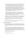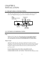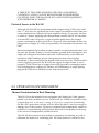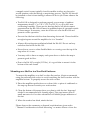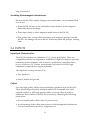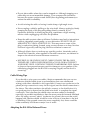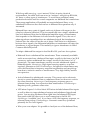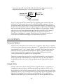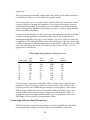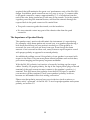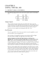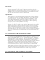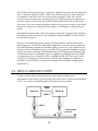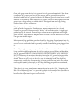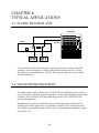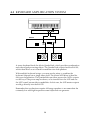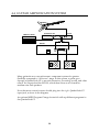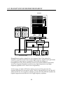
1
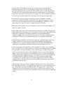
ALESIS
RA-100
Reference Manual
CHAPTER 1 – GETTING TO KNOW THE RA-100
1.1 INTRODUCTION.....................................................................................1
Principal Features................................................................................1
Unpacking and Inspection.................................................................3
About This Manual.............................................................................4
CHAPTER 2 – INSTALLATION
2.1 REAR PANEL CONNECTIONS............................................................5
2.2 POWER CONSIDERATIONS.................................................................5
Fuse.........................................................................................................5
The AC Cord.........................................................................................5
Electrical Service to the RA-100........................................................6
2.3 OPERATING ENVIRONMENT............................................................6
Thermal Considerations in Rack Mounting.................................6
Mounting on a Shelf or in a Non-Rack Enclosure.......................7
Avoiding Electromagnetic Interference..........................................8
2.4 INPUTS.......................................................................................................8
Input Jack Characteristics...................................................................8
Cables......................................................................................................8
Cable Wiring Tips................................................................................9
Adapting the RA-100 to Balanced Lines.........................................9
2.5 OUTPUTS...................................................................................................11
Connector Options...............................................................................11
Output Cables........................................................................................11
Connecting Cables to Push Connectors...........................................12
The Importance of Speaker Polarity................................................13
CHAPTER 3 – USING THE RA-100
3.1 FRONT PANEL CONTROLS.................................................................14
Volume Controls.................................................................................14
On-Off Switch.......................................................................................14
Mute Switch..........................................................................................15
Clip Indicators.......................................................................................15
3.2 CHECKING FOR PROPER POLARITY.................................................15
3.3 CHOOSING THE CORRECT SPEAKERS.............................................15
3.4 ABOUT GROUND LOOPS......................................................................16
CHAPTER 4 – TYPICAL APPLICATIONS
4.1 STUDIO MONITOR AMP.......................................................................18
4.2 SOUND REINFORCEMENT..................................................................18
4.3 KEYBOARD AMPLIFICATION SYSTEM............................................19
4.4 GUITAR AMPLIFICATION SYSTEM..................................................20
4.5 BIAMP SOUND REINFORCEMENT...................................................21
CHAPTER 5 – MAINTAINANCE/SERVICE
5.1 GENERAL INFORMATION..................................................................22
Cleaning.................................................................................................22
Maintenance.........................................................................................22
Refer All Servicing to Alesis.............................................................22
CHAPTER 6 – TROUBLESHOOTING
Hum........................................................................................................23
No Volume...........................................................................................23
Distorted or Low Level Sound..........................................................23
Thin Sound/Sound that Changes Unpredictably in a Room....23
CHAPTER 7 – SPECIFICATIONS
DO NOT REMOVE THE RA-100 TOP COVER. THERE ARE NO USER
SERVICEABLE PARTS INSIDE. REFER SERVICING TO A QUALIFIED
REPAIR TECHNICIAN.
CHAPTER 1:
MEET THE RA-100
1.1 INTRODUCTION
Principal Features
Congratulations on your purchase of the Alesis RA-100 Reference Amplifier.
With all the wondrous advances in both analog and digital electronics in the
past few years, it’s easy to forget that an audio chain is only as good as its
weakest link. With low-cost digital devices now offering sound quality
unheard of only a few years ago, Alesis has applied its expertise toward
creating a sonically accurate, stable, and affordable stereo power amplifier
that’s suitable for the digital age. Optimized for studio monitoring
applications and moderate-power live performance setups, the amp’s main
features include:
• 100 watts per channel into 4Ω, 75 watts per channel into 8Ω
• Dual clipping indicators alert you of any type of non-linear operation, not
just clipping
• Output short circuit protection to minimize down time and protect the
amplifier’s circuitry
• Massive, conservatively rated, custom-designed extruded heat sinks
(individual for each channel) for cool operation
• No ventilation fan is needed, allowing for quiet operation and reduced
ambient noise in the studio
• Extremely low noise and distortion; suitable for quiet applications such as
recording studios, church installations, and museums
However, some of the RA-100’s most important features are hard to put on a
spec sheet. In a quest for a “musical” sounding power amp that can stand up
to a tough life on the road as well as continuous operation in the studio,
Alesis has made some changes—some minor, and some very significant—to
the standard power amp.
• The RA-100 doesn’t produce any audio transients during power-up or
1
power-down. Nonetheless, there’s a 2-second mute on power-up to
compensate for any pieces of equipment plugged into the RA-100 that
produce transients upon power-up, and receive power at the same time as
the RA-100. Also, because the amp doesn’t produce power on/off thumps
itself, the mute circuit can be pre-power amp. This allows simpler circuitry
than what would be required for shutting down the power amp stages.
• The RA-100’s power supply has plenty of reserve capacity to handle
percussive transients, but if someone kicks the RA-100’s plug out of the
wall, you want all amplification to cease immediately. Therefore, if the
amp senses any loss of power, it instantly mutes the audio.
• Because power-up and -down are noiseless, the on/off switch doubles as a
mute or “panic” button.
• The output stage uses full complementary-symmetry circuitry throughout.
Although there are cheaper ways to design an output stage, this time-tested
approach is generally considered superior to non-complementarysymmetry types. The output devices are rated at 30 Amps of peak current,
and boast a 20 MHz FT (transition frequency) for superior bandwidth.
• Extremely good stability with reactive loads (e.g., speakers and crossovers).
Stable operation is essential when presented with the changing load
characteristics of typical speakers; the RA-100 uses several stabilization
techniques to maintain consistent feedback network characteristics.
• Alesis recognizes that amplifiers will sometimes be driven into clipping—
even though this is not good practice—during a recording session or under
the pressures of live performance. As a result, a great of deal of research
went into creating the best possible clipping entry/recovery characteristics.
Amps with lots of overdrive and saturation tend to create overshoot and
ringing during the clipping process, which degrades the sound; the RA-100
has been designed so that it exhibits very little saturation, even when
overloaded. As a result, it enters and exits clipping very cleanly. Clean
clipping allows the RA-100 to be driven harder, which makes the overall
perceived sound louder.
Monitoring a sine wave being clipped confirms this action. With the RA100, the amp will follow the original input signal as soon as clipping ceases
(a). With some conventional amp designs, the signal will “hang” at the
clipped level for a while before catching up with the input signal (b. This
saturation-caused overshoot can sometimes sound worse than the clipping
itself.
s
2
• No “speaker stress” during shutdown. With traditional protection circuitry,
the act of clamping the output devices to a safe value can make the amp
unstable with particular notes that interact with the speaker resonance,
thus producing oscillation or “motorboating.” This could damage your
speakers. The RA-100 uses an elegant clamping design that observes the
load at all times but also integrates the signal characteristics into the
clamping action. Thus, the clamping action is gentle and, after clamping to
the maximum current encountered in normal operation, will slowly (over
1 to 2 seconds) clamp based on the load and signal characteristics. If the
source of the problem (e.g., a short across the speaker terminals) is
removed, the signal recovers instantly.
• Alesis also recognizes that whatever else, “the show must go on.” As a
result, under conditions of extreme abuse (such as ultra-low speaker
impedances or mounting that allows for no ventilation), the RA-100 will
limit its signal rather than simply shut down. Taken to an extreme, this
will produce distortion but sound will still come out.
To acquaint yourself with the RA-100’s operation, and to use it properly in
various applications, carefully read this manual. Power amplifiers are highcurrent devices that are the next-to-last link in the audio chain. Proper
attention to cabling, power distribution, ground loops, and other topics
covered in this manual is vital to have the RA-100 live up to its full
potential.
As always, we welcome your suggestions and comments concerning this
product, or any other product in the Alesis line.
Unpacking and Inspection
Your new Alesis power amplifier was carefully packed at the factory, and the
container was designed to protect the unit during shipping. Please retain this
container in the highly unlikely event that you need to return the RA-100 for
servicing.
Upon receiving the RA-100, carefully examine the shipping carton and its
contents for any sign of physical damage that many have occurred in transit.
If you detect any damage, do not destroy any of the packing material or the
carton, and immediately notify the carrier of a possible claim for damage.
Damage claims must be made by you. If you picked up your amplifier directly
from an Alesis dealer, contact the dealer.
The shipping carton should contain:
• This instruction manual
3
• Alesis RA-100 power amp with the same serial number as shown on the
shipping carton
• Power cord.
• Four stick-on rubber feet (for shelf mounting, to prevent the RA-100’s
bottom surface from scratching the shelf)
• Alesis warranty card. It is important to register your purchase; if you have
not already filled out your warranty card, please do so now.
About This Manual
The manual presents information in a logical order. Chapter 2 covers
installation, and Chapter 3, how to use the RA-100. Chapter 4 covers several
typical applications. The manual closes with information on
maintenance/servicing, troubleshooting, and operating specifications.
Please remember that a power amplifier is a high-current, high-power device
and should be treated with respect and care. Even if you are an audio veteran,
we urge you to read the entire manual to make the best use of the RA-100.
4
CHAPTER 2:
INSTALLATION
2.1 REAR PANEL CONNECTIONS
The following diagram shows the various rear-panel components. Please
refer to this diagram during the procedures described in this chapter.
Fuse:
5 Amps
(A spare fuse in included in
the fuse holder)
AC Line
Cord Jack
Left Push Clip
Outputs
Right
Left Phone
Input
Plug Output
Right Phone
Plug Output
Left Input
Right Push
Clip Outputs
2.2 POWER CONSIDERATIONS
Fuse
Replace with a 5 Amp, slow-blow type only; use of any higher amperage
value will void the warranty. FUSES ARE FOR YOUR PROTECTION—
NEVER SUBSTITUTE A FUSE OF A HIGHER RATING, OR BYPASS IT.
The AC Cord
The RA-100’s IEC-spec AC cord (do not substitute any other AC cord) is
designed to feed an outlet that includes three pins, with the third, round pin
connected to ground. The ground connection is an important safety feature
designed to keep the chassis of electronic devices such as the RA-100 at
ground potential.
DO NOT OPERATE ANY ELECTRICAL EQUIPMENT WITH
UNGROUNDED OUTLETS. PLUGGING THE RA-100 INTO AN
UNGROUNDED OUTLET, OR “LIFTING” THE UNIT OFF GROUND WITH
5
A THREE-TO-TWO WIRE ADAPTER, CREATES A HAZARDOUS
CONDITION. ALESIS CANNOT BE RESPONSIBLE FOR PROBLEMS
CAUSED BY USING THE RA-100 OR ANY ASSOCIATED EQUIPMENT
WITH IMPROPER AC WIRING.
Electrical Service to the RA-100
Although the RA-100 has a maximum audio output rating of 200 watts total
into 4Ω, this does not represent the total current consumption since there are
certain inefficiencies inherent in linear amplifier design. As a result, the fuse
is rated at 5 Amps, implying that the maximum current the RA-100 can draw
is around 500 watts. However, in typical studio applications the average
power consumption will be much less. However, when multiple devices are
plugged into a single AC outlet, the possibility of overheated connections can
exist.
Electrical standards have taken enormous strides toward increased safety over
the past few decades thanks to circuit breakers, ground fault interrupters, and
improved wiring and insulation materials. Unfortunately, some clubs are
situated in older buildings whose wiring may not meet current safety
standards, or have wiring that has deteriorated over the years. Make sure the
circuit supplying power to the RA-100 can supply enough current to run it
properly. If the circuit has to supply other high-powered consumption units
such as refrigerators, coffee pots, toasters, air conditioning, or stage lighting,
plug the RA-100 into a different circuit with a lesser load.
2.3 OPERATING ENVIRONMENT
Thermal Considerations in Rack Mounting
The RA-100 can be mounted in an equipment rack (taking up 2 rack spaces),
placed on a shelf, tucked away in a vocal booth, etc. When you install it, keep
in mind that heat is the major enemy of electronic equipment. Fortunately,
the RA-100’s protection circuitry will not allow the unit to run hot enough to
damage any of the circuitry. However, sustained high-temperature operation
sufficient to cause limiting will adversely affect the sound quality for as long
as the excessive temperature conditions exists.
The RA-100 has extensive heat sinking to minimize overheating, as well as
eliminate the need for a ventilating fan. The latter feature is crucial for the
6
cramped control rooms typically found in smaller studios; any fan noise
would interfere with the mixing or monitoring process. The RA-100 should
be installed so that its heat sinking is allowed to do its job. Please observe the
following:
• The RA-100 is designed to perform properly over a range of ambient
temperatures from 0° C to +50° C (32° F to 122° F), in up to 80% noncondensing humidity. These are not absolute limits, but Alesis cannot
guarantee that the RA-100 will meet its published specs if operated outside
of these ranges. If necessary, use a fan to blow air over the RA-100 and
promote cooler operation.
• Prevent the side heat sink fins from becoming obstructed. There should be
enough airspace around the amplifier for it to “breathe.”
• Always allow adequate ventilation behind the RA-100. Do not seal any
enclosure that holds the RA-100.
• Never throw a coat or other flexible fabric or covering over the top of the
amp when it’s in use.
• You may wish to leave an empty rack space above or below the amp to
promote good air flow.
• Due to the RA-100’s weight (13.5 lbs.), it’s a good idea to mount it in the
bottom of the rack frame.
Mounting on a Shelf or in a Non-Rack Enclosure
To mount the amplifier on a shelf or other flat surface, Alesis recommends
using the enclosed stick-on feet to avoid scratching the shelf’s surface with the
amplifier bottom. To properly mount the stick-on feet:
1 Place the amplifier upside down on a clean cloth or piece of cardboard so
the amp top does not scratch your work surface.
2 Clean the bottom of the amp where you plan to stick the feet. Isopropyl
alcohol is recommended as a cleaning agent. This step insures that no
small amounts of oil or other substances will inhibit proper adhesion of
the feet.
3 When the surface has dried, attach the feet.
Please observe the comments on thermal considerations given under
“Thermal Considerations in Rack Mounting” no matter where or how the
7
amp is mounted.
Avoiding Electromagnetic Interference
Because the RA-100 contains a large power transformer, we recommend that
you do not:
• Place the RA-100 next to an unshielded video monitor, as the magnetic
fields may distort the image.
• Place tapes, disks, or other magnetic media close to the RA-100.
• Play guitar, bass, or any other instrument with magnetic pickups near the
RA-100. No damage will occur but AC fields may enter the pickups, causing
hum.
2.4 INPUTS
Input Jack Characteristics
The RA-100 includes two unbalanced, 1/4" phone jack inputs. These are
compatible with the low-impedance, unbalanced, high level outputs typically
emanating from equipment such as mixers, synthesizers, samplers, direct
boxes, crossovers, etc. Guitars, microphones, and other low-level/highimpedance output devices require a preamp.
The input jack wiring convention is:
• Tip: signal hot
• Sleeve: shield and ground
Cables
Use only high quality cables when interfacing equipment with the RA-100.
These should be good quality shielded cables with a stranded (not solid)
internal conductor. Although quality cables cost more, they do make a
difference. Route cables to the RA-100 correctly by observing the following
precautions.
• Do not bundle audio cables with AC power cords.
• Avoid running audio cables near sources of electromagnetic interference
such as transformers, monitors, computers, etc.
8
• Do not place cables where they can be stepped on. Although stepping on a
cable may not cause immediate damage, it can compress the insulation
between the center conductor and shield (thus degrading performance) or
reduce the cable’s reliability.
• Avoid twisting the cable or having it make sharp, right angle turns.
• Never unplug a cable by pulling on the wire itself. Always unplug by firmly
grasping the body of the plug and pulling directly outward. If you
experience difficulty in removing the plug, sometimes a slight rotating
motion while unplugging will solve the problem.
• Keep the cable contacts clean at all time. Oxidation may lead to intermittent
contacts, degraded sound quality, or even distortion. DO NOT USE AN
ABRASIVE TO CLEAN A DIRTY PLUG. This may remove some of the
plug’s conductive plating. Instead, spray contact cleaner on a clean, lint-free
cloth and vigorously rub the plug until the oxidation is removed.
• Although Alesis does not endorse any specific product, chemicals such as
Tweek and Cramolin, when applied to electrical connectors, are claimed to
improve the electrical contact between connectors.
• NEVER PLUG OR UNPLUG INPUT CABLES UNLESS THE RA-100 IS
TURNED OFF, UNPLUGGED FROM THE AC LINE, OR HAS THE LEFT
AND RIGHT LEVEL CONTROLS TURNED TO MINIMUM LEVEL. Failure
to observe these precautions may result in damage to your speakers if the
cable being plugged into the RA-100 is carrying a signal, and the level is
turned up.
Cable Wiring Tips
If you decide to wire your own cables, Alesis recommends that you use two
conductor shielded cable (even in an installation that uses unbalanced
wiring) with either a braided or foil-type shield. Connect one conductor to the
phone jack tip connection to carry the hot signal, and the shield connection to
the sleeve. The other conductor should also connect to the shield since it is
not good practice to depend on the shield wire itself to complete the signal
connection. This is because the shield wires are more subject to breakage,
especially in portable installations, than the more protected internal insulated
wires. By using a second “safety” conductor for ground, the worst that could
happen with a broken shield would be a rise in noise or hum due to the lack
of shielding. If the ground connection were completely lost, there would be
either extremely loud hum or major loss of audio.
Adapting the RA-100 to Balanced Lines
9
With long cable runs (e.g., over 6 meters/20 feet) in noisy electrical
environments, the cable itself can act as an “antenna” and pick up RF fields,
AC hum, or other types of interference. To avoid these problems, many
professional studios and live sound companies use balanced line connections.
The average application will probably not require balanced lines, so try
unbalanced connectors first and convert to balanced line operation only if
warranted.
Balanced lines carry a pair of signals, each out of phase with respect to the
other but otherwise identical. To be converted back into a single, unbalanced
line, both balanced lines feed a differential amplifier input or transformer
that responds to the difference in levels between signals. Thus, the out-ofphase signals are recombined into an unbalanced signal, but interference
induced into the cable will not be out of phase. Since there is no difference
between these signals, the differential amplifier or transformer will reject the
interference to a great degree. This tendency to ignore interference is called
Common Mode Rejection.
To adapt a balanced line output to feed the RA-100, you have four options.
• Balanced line to unbalanced line transformer. These commonly available
audio accessories have a balanced line input, usually in the form of an XLR
connector, and an unbalanced line output, usually in the form of a 1/4"
phone jack. The same transformer can also convert unbalanced signals to
balanced signals. Advantages: High signal carrying capacity, no power
required, generates no hiss. Disadvantages: Inexpensive transformers may
color the sound due to frequency response irregularities and can pick up
hum due to inductive nature of transformers. Very high-fidelity models
are expensive.
• Active balanced-to-unbalanced converter. This uses an active electronic
circuit to convert balanced lines to unbalanced lines, but does not work in
the other direction. Advantages: Good frequency response specs, no
inherent hum pickup, less expensive than transformers. Disadvantages:
Requires power, generates some noise.
• 1622 mixer. Inputs 1-8 of the Alesis 1622 mixer include balanced line inputs
as well as direct-to-tape unbalanced outputs and unbalanced signal send
points. You can plug a balanced line signal into the balanced XLR input,
then patch either the direct out or send connection to the RA-100.
Advantages: Available “free” if you have a 1622, flat frequency response, no
inherent hum pickup. Disadvantages: Generates some hiss, optimized
primarily for low level signals.
• Wire your own adapter. It is possible to feed just one of the balanced lines,
10
along with ground, into the RA-100. The following diagram shows an
adapter that assumes pin 2 of the XLR connector is “hot.”
Female XLR
Connector
2
shield
1/4 inch
phone jack
1
3 (no connection)
If pin 3 is hot, then do not connect pin 2 to anything, and connect the wire
from the 1/4” phone jack tip to pin 3 of the XLR female connector. If your
system uses stereo phone jacks to carry balanced line signals (the tip and ring
should carry the in-phase and out-of-phase signals, respectively, although this
may be reversed in some systems), then an adapter is not necessary. Simply
plug a stereo cord from the balanced phone jack into the RA-100’s input; it
will ignore the ring connection and amplify only the tip connection.
Advantages: Inexpensive, simple. Disadvantages: No inherent hum and
noise rejection; defeats advantages of balanced line operation
2.5 OUTPUTS
Connector Options
The RA-100 is intended to drive loads of 4Ω or greater. There are two speaker
connection output options for each channel: 1/4" mono phone jack, and push
clip terminals (red = “hot” output, black = ground). Push connectors are the
preferred choice for permanent installations. There is greater surface area
contact than with phone connectors, thus promoting a better electrical
connection between the speaker wire and amplifier.
Phone jack connections are used for sound reinforcement or any situation
when quick setup and breakdown are important. You are also less likely to
accidentally reverse the wires if they are permanently connected to phone
plugs.
Output Cables
Speaker cables must deliver large amounts of peak current to a speaker. To
complicate matters further, a speaker represents an inductive load, and is
more difficult to drive than a purely resistive load. Speakers are also very low
impedance devices. Any resistance between the amp output and speakers will
degrade the damping factor, efficiency and ultimately, the sound quality.
Therefore, the cables you use between the RA-100 and its speakers are very
11
important.
Alesis recommends stranded, rather than solid, cables for flexibility and ease
of installation. However, solid cables are equally usable.
Never use guitar cords as speaker cables. Because they lack sufficient currentcarrying capacity, the amp and speakers will not perform properly and the
sound may be degraded. If you make your own cables use electrical zip cord,
which is designed to handle several amps of current, or heavy-gauge speaker
cables if possible/affordable.
In any event, the thicker the cable, the lower the resistance and the better the
current-carrying capability. Standard hookup wire is not acceptable; the
minimum acceptable wire type is the common “zip cord” used to connect AC
to appliances. The following table relates the wire gauge to the how many feet
of cable is required at different impedances to produce a 1 dB power loss. . The
lower the resistance, the better. For cables run up to about 25 feet, 16 to 18
gauge wire is satisfactory.
Cable length that produces 1 dB of power loss
wire gauge
6
8
10
12
14
16
18
20
22
at 4Ω
feet
1200
800
475
300
190
120
75
50
30
at 4Ω
meters
366
244
145
91
58
37
23
15
9
at 8Ω
feet
2425
1600
950
600
375
240
150
100
60
at 8Ω
meters
740
488
290
183
114
73
46
30
18
In recent years, expensive audiophile cables of high current capacity have
appeared. These have been somewhat controversial; some feel the extra
expense produces an audible improvement in sound quality, while others
find no sonic difference between audiophile cables and other heavy-duty
wiring. While Alesis does not endorse any particular brand of cable, we
suggest that you investigate different cable types for yourself to discover if
they improve the sound of your particular setup.
Connecting Cables to Push Connectors
The RA-100 push connectors are perfect for studio installations, especially
near field monitor usage, where an effective and reliable connector is
12
required that still maintains the great cost/performance ratio of the RA-100's
design. In addition, push connectors are very easy to set up. To connect cable
to the push connectors, remove approximately 1/4" of insulation from the
end of the wire, being careful not to nick any of the strands. Twist the strands
together, press the push terminal button, and feed the strands through the
exposed hole in the push connector. Be careful that:
• The push connector grabs the strands, not the insulation
• No stray strands contact any part of the chassis other than the push
connector.
The Importance of Speaker Polarity
The speaker cone’s motion should mimic the instrument it’s reproducing.
For example, a kick drum pushes air toward you, so a speaker reproducing a
kick drum should have its cone push air toward you. If the polarity is
reversed, the cone will suck air away from you. Even though the same
amount of air is moved in either case, many listeners report superior sound
with proper polarity as opposed to reversed polarity.
An additional problem occurs if the polarity of one speaker is reversed with
respect to the other. This can cause phase-related problems such as thin bass,
poor stereo imaging and frequency response anomalies.
With the RA-100, polarity is a function of correctly hooking up the output
cables. Usually, for proper polarity, the tip of the output phone plug or the red
terminal of the push connector must connect to the speaker’s positive (+)
terminal. This will insure that polarity from the RA-100 input to speaker
cone motion will be consistent. Check your speakers' polarity, however,
because not all brands follow this wiring convention.
Please note that polarity reversal can occur in devices (such as mixers or
effects units) “upstream” of the RA-100. To test for proper speaker and system
polarity, see section 3.2.
13
CHAPTER 3:
USING THE RA-100
3.1 FRONT PANEL CONTROLS
The following diagram shows the various front panel controls, as described
next.
Volume Controls
These regulate the input signal going into the RA-100. Always turn the
volume controls all the way down (counterclockwise) when making input or
output connections to the RA-100. Power should be off as well. It’s also good
practice to turn the volume controls all the way down when turning on
power just in case a signal source feeding the RA-100 is “live.”
On-Off Switch
Press the upper half of this rocker-type switch to turn the amplifier on, and
the lower half to turn the amplifier off.
Upon turning on the amplifier, the green power indicator LED will light.
Note that in direct sunlight, this light may not be easily visible.
WHEN TURNING ON AND OFF THE GEAR IN A SYSTEM, IT IS
IMPORTANT TO TURN ON THE POWER AMP LAST AND TURN IT OFF
FIRST. Devices that are amplified by the RA-100 may generate thumps or
other transients on power-up; if the RA-100 is on, these transients could be of
sufficient amplitude to damage your speakers, especially if system levels were
inadvertently set too high. Conversely, some units also create transients
when turned off. For this reason, the RA-100 should always be turned off first.
However, Alesis realizes that in many applications the RA-100 power switch
will be left on and the RA-100, along with other gear, will be switched on by a
master AC switch. As a result, there is a brief delay to allow other equipment
in your system to settle down after receiving power. After this delay, during
which the other units will have presumably made all the noises they were
going to make, the RA-100 will be ready for operation.
14
Mute Switch
Because turning the RA-100 on and off generates no spikes within the
amplifier, the power switch doubles as a mute switch or “panic button.” For
example, if there is a serious feedback problem, you can simply turn off the
RA-100, then chase down the source of the problem.
Clip Indicators
These improve on conventional clipping indicators by showing whenever
any conditions occur that could lead to non-linearity, such as an extremely
out-of-spec load (e.g., too many speakers connected in parallel or a short
across the speaker terminals). Even if the problem occurs for only a few
microseconds, a pulse-stretching circuit will allow the LED to light long
enough for you to see that a problem is occurring.
Because of the RA-100’s ability to enter and exit clipping with as few audible
artifacts as possible, you may not hear any distortion even if the indicator
flashes. In general, a few flashes every now and then will not be a problem.
However, if the LEDs flash often or remain on for any extended period of
time, then turn down the volume controls to reduce the signal level going to
the RA-100. If this doesn’t solve the problem, check your output cables and
speakers.
3.2 CHECKING FOR PROPER POLARITY
To check for correct speaker polarity, briefly connect the + terminal of a 1.5V
battery to the speaker cable’s “hot” or + lead, and the battery’s - terminal to
the speaker cable’s “cold,” ground, or - lead. You will hear a “pop” from the
loudspeaker as you connect the battery, and another as you disconnect it.
Observe the direction of the speaker cone movement. If the speaker cables are
wired in the common manner (and the speakers themselves are not
mislabelled), the speaker cone will move forward (toward you) when you
connect the battery and away from you when the battery is disconnected.
If the speaker cone moves in the opposite direction, reverse the wires going to
the speaker and re-test for proper polarity. Always check your speakers'
polarity as not all manufacturers follow the same wiring convention.
3.3 CHOOSING THE CORRECT SPEAKERS
15
Near-field monitoring through “reference” speakers has become the preferred
way to monitor and mix music. With near-field monitoring, small speakers
are placed so that they are a few feet from the engineer’s ears. As a result,
room acoustics become less important since the primary acoustic interaction
involves direct sound from the speakers rather than reflected sounds from
the room. Since few home and project studios have good acoustics, near-field
monitors can provide realistic monitoring in a small space at relatively low
levels.
Near-field monitors offer other advantages compared to large studio speakers,
including smaller size, lower cost, and easier transportability to other studios
for reference purpose.
Because of its moderate power rating, excellent fidelity, and lack of a noisegenerating fan, the RA-100 “Reference Amplifier” excels in driving reference
near-field monitor speakers in smaller studios. However, you should choose
speakers that can handle the power the RA-100 can generate. Speaker wattage
ratings are often confusing, and standards by which ratings are obtained vary
from manufacturer to manufacturer. If a speaker can handle 100 watts RMS
continuous power, it should be able to handle the RA-100. However, under
conditions of clipping or other abuse of the RA-100, damage to speakers is
possible. For best results, use speakers designed for medium- to high-power
applications.
3.4 ABOUT GROUND LOOPS
A hum or buzz may be introduced into some audio systems by a
phenomenon known as a ground loop. This can occur if a piece of equipment
“sees” two or more different paths to ground, as shown below.
shielded
cable
Device B
Device A
path 1
path 2
To AC power
service
16
One path goes from device A to ground via the ground terminal of the threeconductor AC power cord, but A also sees a path to ground through the
shielded cable and AC ground of device B. Because ground wires have a small
amount of resistance, small amounts of current can flow through ground and
generate a voltage along the cable shield. This signal may end up getting
induced into the hot conductor.
The loop can also act like an antenna into which hum is induced, or can even
pick up radio frequencies. Furthermore, many components in a circuit
connect to ground. If that ground is “dirty” and contains noise, it might get
picked up by the circuit. Ground loops cause the most problems with highgain circuits, since massive amplification of even a couple millivolts of noise
can give an audible signal.
Most ground loop problems can be solved by plugging all equipment into the
same grounded AC source. However, it is important to make sure that the AC
source is not overloaded and is properly rated to handle the gear plugged into
it.
For really tough cases, you may need to break the connection that causes the
loop condition. Although some do this by using a ground lifter and breaking
the AC ground, THIS IS A DANGEROUS OPTION WHICH YOU SHOULD
NOT USE because it sacrifices the safety factor the AC ground wire provides.
In the previous diagram, a better option would be to interrupt the cable
shield. There are two ways to do this: one is to simply break the shield at
some point, usually by disconnecting it from ground at one jack. (The other
end should remain connected so that the shielding properties are retained,
even if there is no direct path for ground.)
The other is to use a transformer as mentioned in section 2.4, “Adapting the
RA-100 to Balanced Lines,” to provide isolation in the audio line between the
two pieces of gear. Transformers generally have no ground connection
between the input and output connections.
17
CHAPTER 4:
TYPICAL APPLICATIONS
4.1 STUDIO MONITOR AMP
1622 Mixer
Monitor
Outputs
RA-100
in
in
out
out
Near-Field monitors
In the studio, the RA-100 is ideal for driving near-field or other reference
speakers. In this example, an Alesis 1622 mixer feeds the RA-100, which
provides power amplification. The RA-100 outputs feed a set of near-field
monitor speakers.
4.2 SOUND REINFORCEMENT
For auditorium and live music use, the RA-100 has sufficient power to drive
a set of small-to-medium size club speakers. The hookup diagram is the same
as above, with an Alesis 1622 mixer feeding the RA-100, and the RA-100
driving the speakers.
Biamplification often provides better live sound and greater efficiency by
splitting the audio signal into two different channels. One channel drives a
low frequency speaker system and the other, a high frequency speaker system.
See Section 4.5.
18
4.3 KEYBOARD AMPLIFICATION SYSTEM
Inputs
Quadraverb
Outputs
RA-100
in
in
out
out
A stereo keyboard feeds the Alesis QuadraVerb, which provides reverberation
and other signal processing effects. The QuadraVerb outputs feed the RA-100,
which then drives a set of small-to-medium size club speakers.
With multiple keyboard setups, you may need a mixer to combine the
keyboard outputs into a single stereo feed. The Alesis 1622 Mixer is ideal for
this type of application. The QuadraVerb can either process the 1622’s outputs
on the way to the power amp as shown, or be inserted into the 1622 and use
the 1622’s send/return effects capabilities. In this case, the 1622 master outputs
would go directly into the RA-100.
Remember that synthesizers require full-range speakers to accommodate the
extremely low and high frequencies some keyboards can generate.
19
4.4 GUITAR AMPLIFICATION SYSTEM
MIDI Foot Pedal
Inputs
Quadraverb GT
MIDI In
Outputs
RA-100
in
in
out
out
Speakers
Many guitarists now use rack mount, component systems for greater
flexibility compared to “all-in-one” amps. In this system, a guitar goes
through a QuadraVerb GT to provide distortion, chorusing, reverb, and other
effects. Its outputs feed the RA-100, which then drives a set of small-tomedium size club speakers.
Note that mono sound sources should plug into the right QuadraVerb GT
input jack, as show in the diagram.
An optional MIDI Program Change footswitch calls up different programs in
the QuadraVerb GT.
20
4.5 BIAMP SOUND REINFORCEMENT
1622 Mixer
Low Frequency Speakers
High
Frequency
Outputs
Low
Frequency
Outputs
Ins
Crossover
High Frequency RA-100
in
in
out
Outs
out
Ins
Low Frequency RA-100
High Frequency Drivers
Biamplification splits a signal into two separate lines. One carries low
frequency signals and the other carries high frequency signals. Each split feeds
its own power amp and set of speakers. The main advantages of
biamplification are greater efficiency and lower intermodulation distortion
since low frequency speakers need not carry high frequencies (and high
frequency speakers won’t receive low frequencies).
In this setup, an Alesis 1622 mixer feeds a crossover that generates the
separate high and low frequency splits. The low frequencies go to one RA-100
which drives the low frequency speaker system; the other RA-100 handles the
higher frequencies and drives a set of high frequency speakers.
21
CHAPTER 5:
MAINTENANCE/SERVICE
5.1 GENERAL INFORMATION
Cleaning
Disconnect the AC cord, then use a damp cloth to clean the amplifier’s metal
and plastic surfaces. For heavy dirt, use a non-abrasive household cleaner
such as Formula 409 or Fantastik. DO NOT SPRAY THE CLEANER
DIRECTLY ONTO THE FRONT OF THE UNIT AS IT MAY DESTROY THE
LUBRICANTS USED IN THE SWITCHES AND CONTROLS! Spray onto a
cloth, then use the cloth to clean the unit.
Maintenance
Here are some tips for preventive maintenance.
• Do not remove the RA-100 top cover. There are no user serviceable parts
inside. Refer servicing to a qualified repair technician.
• Periodically check the AC cord for signs of fraying or damage.
• If you use the push connector output terminals, check that the cables are
securely in place and that no strands short to the chassis or any other
terminal.
• Periodically rotate the volume controls (make sure power is off). In many
applications the volume controls will be set to a particular point and not
adjusted. Occasional rotation of the volume controls will minimize buildup of dust on the potentiometer wiper, thus minimizing scratchiness as the
unit gets older.
• Place a dust cover over the RA-100 when it is not in use.
Refer All Servicing to Alesis
Alesis has spent a great deal of effort researching power amplifier reliability.
We believe that the RA-100 is one of the most reliable amplifiers that can be
made using current technology, and should provide years of trouble-free use.
WARNING: The full AC line voltage, as well as high voltage/high current
DC voltages, are present at several points within the chassis. Service on this
product should be performed only by qualified technicians. THERE ARE NO
USER-SERVICEABLE PARTS INSIDE.
22
CHAPTER 6:
TROUBLESHOOTING
Begin the troubleshooting process by re-reading the manual to make sure you
didn’t miss some important point regarding the unit’s operation. After that,
try the following techniques for specific problems.
Hum
Turn down the volume controls. If the hum goes away, then the source of the
hum is either in a unit feeding the RA-100, or in the input cables feeding the
RA-100. Check your cables and other units.
If the hum persists, there may be a ground loop. Follow the advice given in
section 3.4. Also, check to see that the RA-100 is not situated near other
devices with large external hum fields.
If a loud hum continues, there may be a problem within the RA-100.
No Volume
Turn up the volume controls with no signal feeding the RA-100, and listen
very carefully to the speakers. If you hear any hum or noise, no matter how
low level, then the RA-100 is receiving power and the problem probably lies
in the equipment or cables feeding the RA-100.
If the speakers are absolutely dead and make no noise whatsoever, check the
speaker cabling.
Distorted or Low Level Sound
If either of these problems occurs after the RA-100 has been on for a long time
and running under a heavy load, it is possible that the output protection
circuitry has kicked in. Let the unit rest for a minute by turning off the power
and see if the problem goes away. If it does, check for thermal problems such
as obstructed air flow around the unit.
Bad cables can also cause distorted or low level sound—yet another argument
for using the best cables you can afford.
Thin Sound/Sound that Changes Unpredictably in a Room
This is generally the result of mismatched speaker polarity. Refer to section
3.2 for information on how to test for proper polarity.
23
CHAPTER 7:
SPECIFICATIONS
24