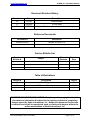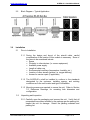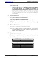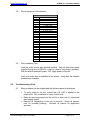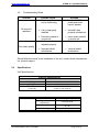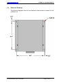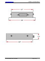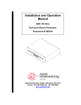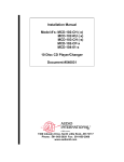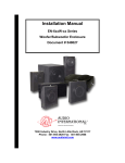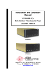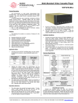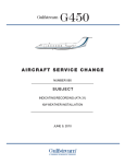
1
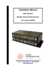
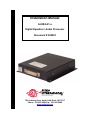
Installation Manual
AI-DEQ-01-x
Digital Equalizer / Audio Processor
Document # 540023
a DeCrane Aircraft Company
7300 Industry Drive, North Little Rock, AR 72117
Phone: 501-955-2929 Fax: 501-955-2988
www.audiointl.com
Audio International, Inc.
AI-DEQ-01-x Installation Manual
Document Revision History
Rev. Level
Date
Description
IR
11/1997
Initial Release
A
04/2000
ECN # 4889
B
02/2002
Updated D-sub connector information, added photo
Reference Documents
Document #
Description
523620 Rev IR1
Outline, AI-DEQ-01-x
Service Bulletin List
Service
Bulletin #
Subject
Manual
Revision
Revision
Date
Table of Illustrations
Section #
Description
Page #
2.2
Block Diagram
5
6.0
Reference Drawings
11-12
PROPRIETARY INFORMATION NOTICE: Despite any other copyright notice, this
document and information disclosed herein contains confidential, proprietary
designs owned by Audio International, Inc. Neither this document nor the data
contained herein shall be reproduced, used, or disclosed to anyone without the
written authorization of Audio International, Inc.
Document #540023, Rev. B, 02/2002
Page 2 of 12
Audio International, Inc.
AI-DEQ-01-x Installation Manual
Table of Contents
Section
1.0
1.1
1.2
1.3
Description
General Information ……………………………………………..
Introduction …………………………………………………………
Purpose of the Equipment ………………………………………..
Optional Equipment ……………………………………………….
Page
4
4
4
4
2.1
2.2
Application ………………………………………………………...
Introduction …………………………………………………………
Block Diagram ..……………………………………………………
4
4
5
3.1
3.2
3.3
3.4
3.5
3.6
3.7
3.8
3.9
Installation …………………………………………………………
Prior to Installation …………………………………………………
Unpacking and Inspection ………………………………………..
Cautions & Warnings ……………………………………………...
Wiring Requirements ……………………………………………...
Physical Characteristics …………………………………………..
Electrical Characteristics ………………………………………….
Mating Connector Information ……………………………………
Pinout Assignments and Descriptions …………………………..
Post-Installation Test ……………………………………………...
5
5
5
6
7
8
8
8
9
9
4.1
4.2
Troubleshooting ………………………………………………….
General Troubleshooting Procedures …………………………...
Troubleshooting Chart …………………………………………….
9
9
10
5.0
Specifications ……………………………………………………
10
6.0
Reference Drawings ……………………………………………..
11
2.0
3.0
4.0
Document #540023, Rev. B, 02/2002
Page 3 of 12
Audio International, Inc.
AI-DEQ-01-x Installation Manual
Model # AI-DEQ-01-x
Digital Equalizer / Audio Processor
1.0
General Information
1.1
Introduction
This manual contains information for the proper installation of the Audio
International, Inc. (AI) Digital Equalizer / Audio Processor, Model Number
AI-DEQ-01-x. The “-x” suffix in the model number designates the type of
connector utilized; “-1” = Positronic and “-2” = D-Subminiature. Also
included are the physical and electrical characteristics of the unit.
1.2
Purpose of the Equipment
Audio International’s AI-DEQ-01-x is a professional digital equalizer /
audio processor. The equalizer provides the passengers the ability to
select up to eight (8) programmed music styles. The unit is built to rugged
aircraft standards and is easily incorporated into new or existing cabin
audio systems.
1.3
Optional Equipment
Audio International, Inc. offers a comprehensive family of Cabin Control
Modules. These modules provide convenient solutions for a variety of
frequently encountered interfacing needs or special requirements and are
an important part of AI’s “building block” system for configuring total cabin
management.
Contact your AI representative for details.
2.0
Application
2.1
Introduction
The purpose of the audio equalizer is to compensate for the frequencies
that might be absorbed by the aircraft interior. The equalizer adjustments
are most effective when made after the aircraft interior is thoroughly
furnished and all pieces of furniture are in place. The AI-DEQ-01-x audio
equalizer also tunes to preferred music styles. Through passenger
controls, the AI-DEQ-01-x can select the programmed music style.
Document #540023, Rev. B, 02/2002
Page 4 of 12
Audio International, Inc.
2.2
3.0
AI-DEQ-01-x Installation Manual
Block Diagram – Typical Application
Installation
3.1
Prior to Installation
3.1.1 During the design and layout of the aircraft cabin, careful
consideration of the location of this module is necessary. Some of
the items to be considered include:
• Space
• Proximity to other devices (i.e. source equipment)
• Available power supply
• Length of cable runs
• Environmental conditions (temperature, humidity, etc.)
• Location of other aircraft systems (i.e. oxygen delivery)
• Access for service repair (if applicable)
3.1.2 The AI-DEQ-01-x shall be installed to conform to the standards
designated by the customer, installing agency, and existing
conditions as to the unit location and type of installation.
3.1.3 Mounting screws are required to secure the unit. Refer to Section
7.0, Reference Drawings, for mounting hole diameters and
configuration.
3.2
Unpacking and Inspection
3.2.1 Carefully open the packaging and remove the unit. Verify that all
components have been included in the package per the packing list.
Inspect the unit for damage. Retain the packing materials and
packing list.
Document #540023, Rev. B, 02/2002
Page 5 of 12
Audio International, Inc.
AI-DEQ-01-x Installation Manual
3.2.2 If damage has occurred during shipping, a claim must be filed with
AI within 24 hours and a Return Request Authorization Number
must be obtained from AI. Refer to the front cover of this manual
for address and telephone number of Audio International.
Repackage the unit in its original packaging materials and return it
to AI following instructions given by the AI representative. If no
return is necessary, retain the packing materials for storage or
reshipment if necessary.
3.3
Cautions and Warnings
3.3.1 It is important to do a pin-to-pin power and ground check on all
connectors. Ensure that power and ground are applied only where
specified. Damage to the unit may result if power or ground is
applied to the wrong points.
3.3.2 DO NOT connect or disconnect the module while power is applied.
3.3.3 DO NOT remove any factory-installed screws. Damage to the unit
may result and void any warranties.
3.3.4 DO NOT install near heat sources such as direct sunlight, warm air
exhausts, or heaters.
3.3.5 NO scheduled maintenance is required to ensure continued
airworthiness.
3.3.6 The AI-DEQ-01-x shall be located away from heat sources,
magnetic fields, direct sunlight, and areas with excessive dust. The
unit SHALL NOT be mounted to the skin of the aircraft.
3.3.7 ESD (Electro Static Discharge) guidelines shall be followed.
Document #540023, Rev. B, 02/2002
Page 6 of 12
Audio International, Inc.
3.4
AI-DEQ-01-x Installation Manual
Wiring Requirements
3.4.1 Introduction
The installing agency shall supply and fabricate all external cables
and mating connectors. The length and routing of external cables
must be carefully studied and planned before attempting installation
of the equipment. Allow adequate space for installation of cable
and connectors. Avoid sharp bends and placing cables near
aircraft control cables. Maintain a MINIMUM clearance of three (3)
inches from any control cable.
If wiring is run parallel to
combustible fluid or oxygen lines, maintain a separation of six (6)
inches between the lines.
3.4.2 Power Wires
All power and ground wires shall be 22 AWG, MINIMUM, shielded
twisted pair with the shield properly bonded at one end only. Power
ground wires shall be bonded to electrically conductive chassis
mounting point with <1 Ω resistance or <50 Ω impedance. Protect
power wires with circuit breakers or fuses located close to the
electrical power source bus.
3.4.3 Audio Lines
All audio input and output cables shall be 22 AWG twisted shielded
pair in accordance with the standard military specification of
MIL-DTL-27500 or equivalent unless otherwise specified. All audio
input and output lines require twisted shielded cable with the cable
shields grounded at the source.
3.4.4 Data Bus Lines
The AI-DEQ-01-x is designed to interface with other Audio
International equipment via AI’s proprietary RS-485 serial data bus.
The data bus is to be implemented using a twisted shielded pair
cable in accordance with MIL-DTL-27500 or equivalent. The wire
size for the conductors in this cable shall be 22 AWG, MINIMUM.
Shield pins are available for connecting data bus shields when
required. In the event shield pins are not provided, the data bus
shield must be terminated per AI’s RS-485 specification. All
equipment on the RS-485 data bus shall be connected in a “daisychain” configuration.
AI’s proprietary RS-485 serial data bus specification is available
upon request.
Document #540023, Rev. B, 02/2002
Page 7 of 12
Audio International, Inc.
AI-DEQ-01-x Installation Manual
3.4.5 Device ID Pins
Device ID pins (Pins 14 – 17) are used to provide a unique address
on the RS-485 data bus. The ID pins will allow up to seven (7)
modules to be installed on the aircraft RS-485 data bus. Since the
first ID number is 0, device ID pin connections are not required
when only one (1) unit is used. If more than one (1) unit is
configured on the data bus, connect the respective device ID pins
to ID common.
3.5
Physical Characteristics
3.5.1 Refer to Section 5.0 for unit dimensions.
3.5.2 Refer to Section 6.0 for attachment points.
3.5.3 When mounting the unit, allow sufficient space for mating
connectors.
3.6
Electrical Characteristics
3.6.1 Refer to Section 5.0 for electrical specifications.
3.6.2 One (1) 25-pin connector is located on the unit. This connector
provides +28 VDC power, audio connections, ground, data bus
signals, and ID strapping pins.
3.7
Mating Connector Information
All wiring harnesses to the unit shall be supplied and fabricated by the
installing agency.
AI-DEQ-01-1 Connector Description
RD25F10JVL0
Mating Connector
AI-DEQ-01-2 Connector Description
DBMA-25S
Mating Connector
DB24659
Backshell
D20419-18
Male Screwlock
Document #540023, Rev. B, 02/2002
Page 8 of 12
Audio International, Inc.
3.8
AI-DEQ-01-x Installation Manual
Pinout Assignment Descriptions
Pin #
1
2
3
4
5
6
7
8
9
10
11
12
13
14
15
16
17
18
19
20
21
22
23
24
25
3.9
Pin 1
Description
+28 VDC Power Input
Ground
R+ Audio Input
R- Audio Input
L+ Audio Input
L- Audio Input
R+ Audio Output
R- Audio Output
L+ Audio Output
L- Audio Output
Data Bus A (HI)
Data Bus B (LO)
Data Bus Shield
Unit ID 0
Unit ID 1
Unit ID 2
Unit ID Common
Reserved
Reserved
Reserved
Reserved
Reserved
Reserved
Reserved
Reserved
Post-Installation Test
Load the audio source with selected material. Any unit that relays audio
outputs through the AI-DEQ-01-x may be used to test proper operation.
With the aircraft and audio power “ON”, apply power to the unit.
Verify that audio input is available to the system. Verify that the selected
material may be heard.
4.0
Troubleshooting Guide
4.1
Many problems can be isolated with the following general techniques:
•
•
•
To verify power to the unit, ensure that +28 VDC is applied to the
proper pins. Use a voltmeter to verify correct level.
Reset by removing power from the unit for at least one (1) minute and
then reapply power.
Recheck all connections to the unit for security. Check all harness
runs for possible pinching. Recheck all pinouts for application
accuracy.
Document #540023, Rev. B, 02/2002
Page 9 of 12
Audio International, Inc.
4.2
AI-DEQ-01-x Installation Manual
Troubleshooting Guide
Problem
No sound in
speakers
Poor audio quality
Possible Cause
Ø Power amplifier may
not be functioning
•
Solution
Verify +28 VDC
power and audio
input is present
Ø Unit is improperly
installed
•
Uninstall, then
properly reinstall unit
Ø No audio material in
source unit
Ø Audio controls are not
adjusted properly
•
Insert audio material
in source unit
Adjust audio controls
Ø Improper shield
terminations
•
•
Verify all shield
terminations
Should difficulties arise in the installation of the unit, contact Audio International,
Inc. product support.
5.0
Specifications
Unit Specifications:
Physical Specifications
Housing
Weight
Dimensions
(l x w x h)
Electrical
Aluminum
0.55 lb / 0.24 kg
5.0" x 5.0" x 1.1"
13 cm x 13 cm x 2.8 cm
Power
Output Level
Adjustments
Frequency Bands
Data Bus Type
Document #540023, Rev. B, 02/2002
150 mA @ +28 VDC
0 through 50 dB
31, 62, 125, 250, 500, 1k, 2k, 4k,
8k, 16k
AI Proprietary RS-485 Data Bus
Page 10 of 12
Audio International, Inc.
6.0
AI-DEQ-01-x Installation Manual
Reference Drawings
The following diagrams show the unit dimensions and connector locations for the
AI-DEQ-01-x.
Document #540023, Rev. B, 02/2002
Page 11 of 12
Audio International, Inc.
Document #540023, Rev. B, 02/2002
AI-DEQ-01-x Installation Manual
Page 12 of 12