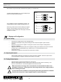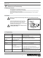
1
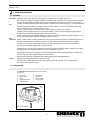
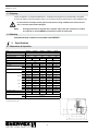
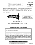
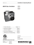
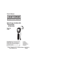
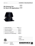
Installation & Operating Manual
3000775 12.12
RSV Chimney Fan
USA
CAN
Product Information ........................ Chapter 1 + 2
Mechanical Installation ......................... Chapter 3
Electrical Installation ............................. Chapter 4
Start Up and Configuration .................. Chapter 5
Maintenance and Troubleshooting ...... Chapter 6
Job Name:
Installer:
Installation Date:
READ AND SAVE THESE INSTRUCTIONS!
ENERVEX Inc.
1685 Bluegrass Lakes Pkwy.
Alpharetta, GA 30004
P: 770.587.3238
F: 770.587.4731
T: 800.255.2923
[email protected]
www.enervex.com
3000775 12.12
1. Product Information
2. Specifications
3. Mechanical Installation
4. Electrical Installation
5. Startup & Configuration
1.1
1.2
1.3
1.4
Function...................................................................................................... 3
Components................................................................................................ 3
Shipping...................................................................................................... 4
Warranty...................................................................................................... 4
2.1 Dimensions & Capacities............................................................................ 4
3.1
3.2
3.3
3.4
3.5
3.6
3.7
3.8
Transport Safety Device.............................................................................. 5
Single Fan on Steel Chimney...................................................................... 5
Singel Fan on Roof Curb............................................................................. 5
Single Fan on Brick Chimney...................................................................... 6
Side-Wall Mounting of Chimney Fan........................................................... 6
Multiple Fan Installations............................................................................. 7
Installation for High Temperatures.............................................................. 7
Installation of Proven Draft Switch (PDS)................................................... 7
4.1 Electrical Requirements.............................................................................. 8
4.3 Wiring Diagram for RSV 400-450................................................................ 9
5.1 System Testing.......................................................................................... 10
5.2 Adjusting Fan Speed................................................................................. 10
5.3 Testing Safety System .............................................................................. 10
6. Maintenance & Troubleshooting
6.1 Maintenance Intervals............................................................................... 11
6.2 Cleaning.................................................................................................... 11
Symbol Legend:
The following terms are used throughout this manual to bring attention
to the presence of potential hazards or to important information
concerning the product.
Caution: Indicates an imminent hazardous situation
which, if not avoided, may result in personal injury or
property damage.
Danger: Indicates an imminent hazardous situation
which, if not avoided, will result in death, serious injury or
substantial property damage.
TO REDUCE THE RISK OF FIRE, ELECTRICAL SHOCK OR INJURY TO PERSONS,
OBSERVE THE FOLLOWING:
5. This unit must be grounded.
1. Use this unit in the manner intended by the manufacturer. If
you have questions, contact the manufacturer at the address or
telephone number listed on the front of the manual.
2. Before servicing or cleaning the unit, switch off at service panel
and lock service panel to prevent power from being switched on
accidentally.
3. Installation work and electrical wiring must be done by a qualified
person(s) in accordance with applicable codes and standards.
4. Follow the appliance manufacturer’s guidelines and safety
standards such as those published by the National Fire Protection
Association (NFPA), and the American Society for Heating,
Refrigeration and Air Conditioning Engineers (ASHRAE), and the
local code authorities.
How to use this manual
This installation manual does not contain any system design
documentation. System design documentation is available from any
authorized EXHAUSTO representative.
Accessories, fans and variable frequency drives are not covered by
this manual. Please refer to these component’s individual manuals.
2
3000775 12.12
1. Product Information
1.1 Function
Description
The RSV chimney fan is intended for use as part of a chimney, stack or venting system. The Use
fan is designed to withstand the high temperatures associated with combustion, and can be used with natural gas,
LP-gas and oil-fired heating appliance systems where flue gases do not exceed 575oF (300oC) for intermittent operation and 482oF(250oC) for continuous operation. It is approved for use with category I, II, III and IV appliances.
The RSV fan may be installed on a traditional vertical chimney system, or as part of a side-wall vented system. Always install the fan at the chimney termination point.
The use of a chimney fan is not restricted to any type of chimney, because the fan creates a negative pressure (below atmospheric) in the chimney system. However, always follow the heating appliance manufacturer’s instructions regarding specific venting requirements. The fan is designed to prevent draft problems by creating mechanical draft in chimney and stack systems. It can
also be used to increase the capacity and efficiency of such a system.
Code
The fan housing is made of heavy cast aluminum and can be opened for easy cleaning. The RSV 200-450 have a
Compliance
backward inclined impeller. It is made of cast aluminum and has permanently attached balancing weights.
The motor is a direct drive, variable speed, class H insulated, high temperature motor. It has permanently lubricated and sealed ball bearings and is maintenance free.
Installations must conform to the requirements of the authority having jurisdiction. Where required by the authority
having jurisdiction, the installation must also conform to the NFPA 31, 54 or 211.
All electrical wiring must be in accordance with the requirements of authority having jurisdiction or, in absence of such requirements, with the National Electrical Code, NFPA 70.
Listing
RSV is tested and listed to UL Standard 378 for Draft Equipment and CAN3-B255-M81 for Mechanical Flue-Gas Exhausters (ETL Report 514733).
The RSV Fan is a listed component in the CASV, Chimney Automation System. The fan is approved for use in dryer venting systems as well.
1.2 Components
The RSV 200-450 Chimney Fan consists of the following
components:
a.
b.
c.
d.
e.
Top section
Bottom section
Motor
Centrifugal impeller
Inlet for impeller
f.
g.
h.
i.
Locking hinge
Bird screen
Carrying handle
Wiring conduit
Fig. 1
Max. 575°F (300°C)
3
3000775 12.12
1.3 Shipping
The fan is shipped in a corrugated cardboard box. A transport securing device may be attached to the bottom of the fan to hold the motor and impeller in place. Do not remove the device until the fan is at the installation point.
Do not remove the transport securing device until the fan is being installed on the duct or the roof curb. The motor shaft could be damaged.
NOTE:
All single phase fans are shipped with a capacitor and junction box connected via conduit. The capacitor is located INSIDE the junction box. Please do not discard.
1.4 Warranty
Complete warranty conditions are available from ENERVEX.
2.
Specifications
2.1 Dimensions & Capacities
Model
RSV 200
RSV 250
Discharge
RSV 315
RSV 400
RSV 450
Vertical
Fan Type
Centrifugal Impeller
Max. Discharge Velocity
FPM
1,729
2,222
2,771
2,752
4,134
Actual Discharge Velocity
FPM
2.9 x CFM
1.9 x CFM
1.2 x CFM
5.9 x CFM
1.03 x CFM
Voltage
VAC
1 x 120
RPM
3 x 200-240 / 3 x 400-480
1600
1720
Amps
A
1.4
2.9
5.8
3.5 / 1.8
Motor Output
hp
0.1
0.2
0.5
1.0
2.0
kW
0.10
0.16
0.35
0.75
1.5
lbs
47
60
88
127
155
kg
18
26
35
58
70
in
11.03
13.20
14.97
16.94
23.23
Weight
A
Dimensions
BxB
CxC
DØ
E
mm
280
335
380
430
590
in
15.37
19.11
22.85
25.61
25.61
mm
390
485
580
650
650
in
12.22
15.17
18.32
20.69
20.69
mm
310
385
465
525
525
in
7.88
9.85
12.41
15.76
15.76
mm
200
250
315
400
400
in
3.15
3.94
4.53
5.12
8.54
mm
Motor starter required
Variable speed motor
Temperature Rating
6.5 / 3.6
80
100
115
130
217
No
No
No
Yes 1)
Yes 1)
Yes
Yes
Yes
Yes
Yes
Interm
575°F/300°C
Cont.
482°F/250°C
1) Not required if using a VFD
4
3000775 12.12
3. Mechanical Installation
The code requirements for a mechanical draft system are different than those for a gravity venting system used with
gas or oil-fired applications. Generally, the mechanical draft system must be installed a minimum of 3 feet away
from any forced air inlet located within 10 feet and a minimum of 4 feet away from any door or window. For complete information, consult ENERVEX or your local building codes.
3.1 Transport Safety Device
Before mounting the fan make sure the transport safety
brackets have been removed (RSV315, 400 and 450 only).
Fig. 2
3.2 Single Fan on Steel Chimney
Insert the steel chimney adapter (SCA) into the chimney/stack. The long collar engagement ensures safe anchoring (See Fig. 3).
If necessary, the adapter can be secured by means of long
self-tapping stainless steel screws into the side of the collar
through the chimney wall.
Fig. 3
Place high-temperature silicone on top of the adapter.
Remove the transport securing device (if present) holding the
motor shaft and impeller in place.
Center the fan over the cutout and place on the silicone.
Open the fan housing and secure onto the adapter through
the pre-drilled holes in the bottom of each corner. Use lag bolts
or self-tapping sheet metal screws.
Do not block the (4) drain holes.
3.3 Single Fan on Roof Curb
If the fan is installed on a curb cap, secure the roof curb with
self-tapping sheet metal screws (see Fig. 4).
Place high-temperature silicone on the top of the curb cap around the curb cap opening.
Remove the transport securing device (if present) holding the
motor shaft and impeller in place.
Center the fan on the curb cap and place the fan on the silicone.
Open the fan housing and secure onto the roof curb through
the pre-drilled holes in the bottom of each corner. Use lag bolts
or self-tapping sheet metal screws.
Do not block the (4) drain holes.
Caution: Never place hands or fingers on top of fan
base when closing
5
Fig. 4
3000775 12.12
3.4 Single Fan on Brick Chimney
The installation procedure is the same for round and square flues. If a clay flue liner is installed and extends beyond the chimney,
cut it back so it extends no more than 1/2 inch above the chimney
crown.
Fig. 5
Apply a bead of high-temperature silicone around the edges of the flue tile. Place the fan over the flue and make sure the fan
is completely sealed to the clay tile.
Open the top of the fan housing and secure with anchor bolts through the pre-drilled mounting holes.
3.5 Side-Wall Mounting the Fan
Make sure the vent terminates flush with the wall. Insert the steel
chimney adapter (SCA) and secure it safely to the wall.
Seal around the edges of the adapter flange. Mark the locations of the wall anchors and predrill holes for them.
Turn the fan upside-down and apply a bead of high-temperature
silicone on the base of the housing, close to the outer edge.
Orient the fan so the motor terminal box is pointed upwards. The
hinges on the housing should be on the left-hand side of the installer as shown in Fig. 6.
Open the fan and secure it onto the adapter with wall anchors, through the predrilled holes in the bottom. Make sure the conduit
is located on one of the sides, never on the upside or downside.
Seal around the fan base to make sure it is watertight and no water can slip in between the fan and the adapter.
Do not block the (4) drain holes.
Do not side-wall mount the RSV450.
Caution: Never place hands or fingers on top of
fan base when closing
6
Fig. 6
3000775 12.12
3.6 Multiple Fan Installations
It is possible to install multiple fans in parallel. For details, please contact ENERVEX. The fans must be placed so they can be opened for maintenance and chimney access.
Fig. 8 shows optimal placement.
Fig. 7
3.7 Installation for High Temperatures
If the fan is used for applications where the flue gas temperatures exceed 482°F at the flue exit, dilution air is required.
Dilution air allows cool air to dilute the warm flue gases. The best way to introduce dilution air is through a barometric
damper or draft hood mounted in the chimney system between the appliance outlet and the fan outlet. When introducing dilution air, the fan capacity is reduced and a larger fan may be required.
3.8 Installation of Proven Draft Switch (PDS)
A safety system must be interlocked with the appliance(s). The safety system could utilize a Proven Draft Switch, a thermal switch or a flow switch.
The device must be interlocked with the heating appliance so it shuts down in case of insufficient draft, fan failure
or power failure. Please refer to the PDS-1 Installation Manual if this control is used. For more information on alternative safety systems, please contact ENERVEX, Inc. Fig. 8 shows the location of the stack probe used with the PDS-1. The stack probe should be installed in a location where there is at least 0.05” WC.
A safety device that prevents the heating appliance operation, in case of a power failure or
inadequate draft situation, must be installed.
Fig. 8
If possible, the distance “A” should be equal to 3 times
the diameter of the chimney. This will improve accuracy.
7
3000775 12.12
4. Electrical Installation
4.1 Electrical Requirements
Power requirements depend on the fan size and they can be found on page 4.
Danger: Turn off electrical power before servicing. Contact with live electric components can
cause shock or death.
Notice: If any of the original wire supplied with the system must be replaced, use similar wire
of the same temperature rating. Otherwise, insulation may melt or degrade, exposing bare wire.
4.2 Wiring Diagram for RSV 200-315
The connection diagram below shows a single-phase fan connected to a fan speed control and the power source (see Fig. 9).
Use 2-conductor wire of minimum 14 AWG with ground. Wiring must be run outside the chimney/stack in flexible or
rigid metal conduit.
Fig. 9
8
3000775 12.12
4.3 Wiring Diagram for RSV 400-450
The wiring diagrams below shows a three-phase fan connected to the power source (see Fig. 10).
Use a 3-conductor wire of minimum 14 AWG with ground. Wiring must be run outside the chimney/stack in flexible or
rigid metal conduit.
Where variable speed is required, the fan is connected to a variable frequency drive (VFD). Wire according to Fig. 10
for systems using the ABB ACH550 series VFD.
Fig. 10
9
3000775 12.12
RSV 400-450 can operate at either 3x208-230 VAC (default) or 3x440-480 VAC.
The motor wiring terminals in Fig. 11 show default jumper
positions for 3x208-240VAC operation.
If the application requires 3x440-480VAC operation, the
jumper positions must be changed according to Fig. 12.
Fig. 11
Fig. 12
After wiring, make sure the motor is rotating in the proper
direction. This is marked on the motor end cover. If the
rotation is incorrect, swap the two wires going to the motor
terminals, U1 and W1.
5. Startup and Configuration
5.1 System Testing
•
Check the line voltage with the motor nameplate rating.
•
Check that the transport securing device holding the motor shaft and impeller in place has been
removed.
•
Determine if the axial vane or impeller is running free and has not been subject to misalignment in
shipping or installation.
•
Apply power and check that the axial vane or impeller is rotating in the direction of the arrow on the side
of the top motor cover (RSV400/450 only). All RSV fans run in a clockwise direction when viewed from the top.
•
Switching any two phases in the junction box will reverse the rotation.
5.2 Adjusting Fan Speed
•
Start all heating appliances connected to the chimney with the fan installed. Set the fan speed control
to the speed where no spillage is experienced anywhere in the system.
5.3 Testing Safety System
•
•
Adjust the setting of the Proven Draft System or other device.
Start the heating appliances and the chimney fan to make sure the safety device is functioning. Turn
the fan off. After less than 1-2 minutes all appliances should be shut down.
Make sure the fan is running in the correct direction; the fact that the fan blows is no
guarantee it is doing so. Running the fan in the wrong direction over a longer period of
time will damage the motor.
It is important that the installation, start-up and system testing procedures are followed.
Failure to do so may have a major negative impact on motor expectancy.
10
3000775 12.12
6. Maintenance and Troubleshooting
6.1 Maintenance Intervals
•
•
•
•
The RSV Chimney Fan is designed for continuous use.
For gas applications, no regular maintenance is required.
For oil applications, inspect the axial vane or impeller after (3) months and set up a periodic inspection
based on these findings. Clean as required.
The fan motors are equipped with permanently lubricated sealed ball bearings. They do not require
lubrication.
6.2 Cleaning
Warning: Do not open the motor housing unless power to the chimney fan has been
disconnected.
Fig. 13
•
•
•
Loosen the two Phillips screws in the front of the unit.
Tilt the top of the fan by lifting the hinge. Make sure the
locking arm holds the top of the fan before letting go.
If necessary, use a scraper and a brush to clean the impeller
and the inside fan base (see Fig. 13).
Caution: Never place hands or fingers on top of
fan base when closing
6.3 Troubleshooting
Problem
The fan is not operating.
Possible Cause
No power to the fan.
What to do
Check the power supply wires in the junction box by the fan.
Check the circuit breaker.
Check that the fan is actually turned ON.
The fan is not running
The capacitor is improperly
Check the connections inside the junction box. The capacitor
at full speed and/or is
connected or not connected at all must be installed according to wiring diagram.
humming.
(single-phase fans only).
The fan is rotating
Phase sequence in the power to Swap two phases in the junction box.
backwards (RSV 400/450 the fan is reversed.
only).
The fan is vibrating
The motor shaft is damaged.
Turn the power off immediately. Open the fan and check if the
vigorously.
shaft is straight. If not, contact ENERVEX.
The fan is noisy.
A transportation device has not
Remove the transportation device.
been removed.
Foreign matter is stuck in the fan. Turn off the power and remove the foreign article.
A ball bearing is damaged.
Turn off the power. Wait for the motor to stop revolving. Spin
the wheel and listen for any grinding noise from the motor. If
necessary, replace bearing.
The fan stops in the
The motor is overheating.
Check the flue gas temperature below the fan. The temperature
middle of a firing cycle.
should not exceed 482°F during continuous operation. Call
ENERVEX.
11
3000775 12.12
ENERVEX Inc.
1685 Bluegrass Lakes Pkwy.
Alpharetta, GA 30004
P: 770.587.3238
F: 770.587.4731
T: 800.255.2923
[email protected]
www.enervex.com