1
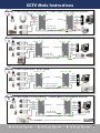
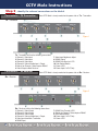
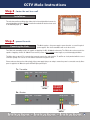
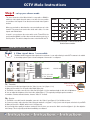
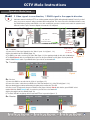
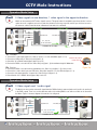
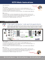
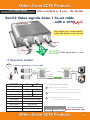
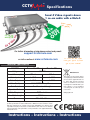
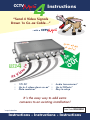
CCTV
TM
ule
Instructions
“Send 4 Video Signals
Down 1x Co-ax Cable...”
...with a
CCTV
TM
ule
MULE
4x
•
•
•
4
o
CCTV
In
Even aud
& data! io
d
Vi
1
G
xR
59
UT
O
e
12V DC
•
Up to 4 videos down co-ax* •
Data combiner*
•
Audio transmission*
Up to 200mtrs*
Easy to setup
It’s the easy way to add extra
cameras to an existing installation!
* as per instructions
Mule4 Instructions
Order Code: MULE004
Instructions - Instructions - Instructions
CCTV Mule Instructions
CCTV
TM
ule
Carries multiple video signals even data down ONE RG59 cable!
The CCTV Mule makes it easy to add extra cameras to existing
installations, you save installation time and reduce the cost of
buying and installing more cable.
The Mules work in pairs. One Mule combines the video signals to transmit them
down 1 single co-ax, the other Mule then reconstructs the individual video
signals at the remote end. A low-cost, easy solution that offers huge installation
benefits and opportunities to add extra cameras.
The clever electronics of the CCTV Mule also allow it to carry audio and RS485
data along the same co-axial cable. You can even carry three video signals in
one direction and a fourth signal in the other direction!
The CCTV Mules need a 12V power supply at both ends but other than that,
it’s a really simple device to use, with no real configuration to do.
Step 1 - decide on the operation mode you require the Mule4 to work in...
It has the following 5 operation modes...
Mode 4 Video signals down 1 co-ax cable
1
Mule 4 - Tx
Mule 4 - Rx
V1
12V DC
12V DC
V4
V4
V1, V2, V3 & V4
in this direction
1x RG59 co-ax cable
2
V2
V3
DVR
V1
V2
V3
CCTV Mule Instructions
Mode 3 Video signals in one direction, 1 RS485 signal in the opposite direction.
2
Mule 4 - Rx
Mule 4 - Tx
V1
12V DC
V2
V3
12V DC
DVR
V1
Data
V2
V3
Data
V1, V2, V3
in this direction
1x RG59 co-ax cable
RS485 Data
Mode 3 Video signals in one direction, 1 video signal in the opposite direction.
3
Mule 4 - Rx
Mule 4 - Tx
V1
V2
V3
V4
V1
DVR
12V DC
V2
V3
V4
12V DC
V1, V2, V3
in this direction
1x RG59 co-ax cable
V4 in this direction
Mode 3 Video signals and 1 audio signal.
4
Mule 4 - Rx
Mule 4 - Tx
V1
12V DC
V2
V3
Audio
12V DC
DVR
V1
V2
V3
Audio
V1, V2, V3 & Audio
in this direction
1x RG59 co-ax cable
Mode 3 Video signals in one direction, 1 audio signal in the opposite direction.
5
Mule 4 - Rx
Mule 4 - Tx
V1
12V DC
12V DC
V2
V3
Audio
DVR
V1
V2
V3
Audio
V1, V2 & V3
in this direction
1x RG59 co-ax cable
Audio in this direction
New VoiceOFF - Alarm activated voice/sound warning unit, see >
3
CCTV Mule Instructions
Step 2 - identify the relevant connections on the Mule4.
Connections - TX Transmitter
Tx - Transmitter
Each CCTV Mule is clearly marked on the power side as: Tx - Transmitter
Figure 1
Tx - Transmitter unit has the following connections;
1. Channel 1 Video Input
2. Channel 2 Video Input
3. Channel 3 Video Input
4. Channel 4 Video or Audio Input - Output
5. Switch, for Channel 4 Video Input or RS485
6. Video Output to Mule Receiver
Connections - RX Receiver
Rx - Receiver
7. Video Input Brightness Adjust
8. RS485 Output
9. RS485 Data Receive L.E.D
10. Gain Control Switch
11. Power L.E.D
12. Power Input 12v D.C Only
Each CCTV Mule is clearly marked on the power side as: Rx - Receiver
Figure 2
Rx - Receiver unit has the following connections;
1. Channel 1 Video Output
2. Channel 2 Video Output
3. Channel 3 Video Output
4. Channel 4 Video or Audio Input - Output
5. Video Input from Mule Transmitter
6. RS485 Input
4
7. RS485 Data Transmit L.E.D
8. Switch, for Channel 4 Video Input or RS485
9. Gain Control Switch
10. Power Input 12v D.C Only
11. Power L.E.D
CCTV Mule Instructions
Step 3 - fasten the unit to a wall
Installation
The units have wall mount fixings lugs either side for internal installation however for
external installation the Mules MUST be installed in a suitable IP rated enclosure such
as the BOX420 (figure 3).
Figure 3
Step 4 - power the units.
Powering the Units
The Mules require a 12v power supply to power the units, so you will require 2
power supplies. One for the transmitter and one for the receiver.
The PSU for the transmitter needs to be capable of supplying 12v D.C. @ 200mA continuously. The PSU for the receiver needs to be
capable of supplying 12v D.C @ 350mA. Please ensure you use a fully regulated power supply or you risk damaging the Mules.
The Mules have a green 2 Pin connector that connects power to the units, both the Tx and Rx are clearly marked with the correct
connection polarity. The red core is +12V and the black is 0v see figures 4 and 5.
Please make sure that you check the polarity of the power supply that you are using to ensure the power is connected correctly. Once
power is applied to the Mules the power LED will light up and stay lit.
Tx - Transmitter
Rx - Receiver
WARNING
POLARITY
SENSITIVE
Figure 4
Figure 5
5
CCTV Mule Instructions
Step 5 - set up your chosen mode.
The clever electronics of the Mule4 allow it to carry audio or RS485 in
addition to video signals along the same co-ax cable. It's even possible
to send three video signals in one direction and a fourth video signal in
another!
Mode
When you send audio or data down the co-ax you actually use up 1 video
channel. This means it can send 3 video feeds and 1 audio, or 3 video
signals and 1 RS485 data.
In mode 2, you need move the sector switch on the TX and RX to the
position marked RS485. In all the other modes the switch needs to be in
the V4 position. The switch is always the same on both the RX and TX.
Tx
Rx
1
V4 or RS485
V4 or RS485
2
V4 or RS485
V4 or RS485
3
V4 or RS485
V4 or RS485
4
V4 or RS485
V4 or RS485
5
V4 or RS485
V4 or RS485
NB: Switches on both Tx and Rx must be set
identical to one another.
Operation Mode Setup
Mode
1
4 Video signals down 1 co-ax cable
The Mule4 allows 4 separate video signals to be sent down 1 co-ax cable allowing 3 extra CCTV cameras to be added
to an existing system. Figure 6 shows a diagram of how mode 1 is configured.
Mule 4 - Tx
Figure 6
Mule 4 - Rx
V1
12V DC
12V DC
V2
V3
V4
DVR
V1
V2
V3
V4
V1, V2, V3 & V4
in this direction
1x RG59 co-ax cable
Tx - Transmitter
Switch in ‘V4’ position
on both units.
V4 or RS485
1. Connect your 4 video input signals into the ‘Video In’ ports 1 to 4 (figure 1, 1-4).
2. Make sure the switch is on V4 position Not RS485 (figure 6a).
3. The RG59 co-ax cable connects to the ‘Video Out’ port (figure 1, 6), the maximum length for this cable is 200 metres.
Figure 6a
4. You can adjust the brightness of the first 3 video inputs (figure 1, 7) if required by turning the grub screw with a
screwdriver clockwise and anticlockwise, however ‘Video In’ 4 is fixed.
Rx - Receiver
1. The RG59 co-ax cable from the transmitter connects to the ‘Video In’ port (figure 2, 5) of the Mule receiver.
2. Connect your video cables from the ‘Video Out‘ ports marked 1 to 4 (figure 2, 1-4) to your 4 video in inputs on the back of your DVR.
3. Make sure that ‘V4 or RS485’ switch is set to V4 (figure 6a).
4. If you find the video quality is low when coming out of the receiver, you can use the ‘Gain’ control knob (figure 2, 9) to fine adjust the
video image. This is especially useful when transmitting over distance.
6
CCTV Mule Instructions
Operation Mode Setup
Mode
2
3 Video signals in one direction, 1 RS485 signal in the opposite direction.
Add extra cameras including a PTZ to an existing system using the RG59 cabling already installed. Perfect if you don’t
have access to run any more cables even data cables underground. The clever electronics of the Mule4 allow it to carry
the RS485 data along the same RG59 co-ax cable enabling the operator to monitor and control the system from a
different location. Figure 7 shows a diagram of how mode 2 is configured.
Figure 7
Mule 4 - Rx
Mule 4 - Tx
V1
12V DC
12V DC
V2
V3
DVR
V1
Data
V2
V3
Data
V1, V2, V3
in this direction
1x RG59 co-ax cable
Tx - Transmitter
RS485 Data
Switch in ‘RS485’
position
1. Connect the 3 ‘Video Input’ signals into the ‘Video In’ ports 1 to 3 (figure 1, 1-3).
on both units.
2. Move the switch from V4 to RS485 (figure 7a).
3. The RG59 co-ax cable connects to the ‘Video Out’ (figure 1, 6), the maximum length for this cable is 200 metres.
4. The RS485 Data A cable of your RS485 device goes into the green ‘RS485’ socket (figure 8 below) marked A
and the RS485 Data B cable of your RS485 device goes into the socket marked B.
V4 or RS485
Figure 7a
Tx - Transmitter
Figure 8
Rx - Receiver
1. Connect the RG59 co-ax cable into the ‘Video In’ port (figure 2, 5).
2. Connect the 3 video cables from your DVR to the ‘Video Out’ marked 1 to 3 of the RX unit (figure 2, 1-3).
Note you should have no cables connected to the video port 4 on either the TX or RX.
3. Connect your PTZ keyboard to the green ‘RS485’ socket (figure 9 below). Data A cable into the green ‘RS485’ socket
marked A and the RS485 Data B cable of your device goes into the socket marked B.
4. Move the switch from V4 to RS485 (figure 7a).
5. The ‘Data’ LED will only light up when a keyboard/PTZ are in operation (figure 2, 7).
Rx - Receiver
Figure 9
7
CCTV Mule Instructions
Operation Mode Setup
Mode
3
3 Video signals in one direction, 1 video signal in the opposite direction.
Mule4 can also transmit a CCTV video signal in reverse. This great feature is an added bonus where wirefree is not an
option due to site conditions such as trees and other obstacles in the way, especially useful if you don’t have access to
run any more cables. Figure 10 shows a diagram of how mode 3 is configured.
Figure 10
Mule 4 - Rx
Mule 4 - Tx
V1
V2
V3
V4
V1
12V DC
V2
V3
V4
DVR
12V DC
V1, V2, V3
in this direction
1x RG59 co-ax cable
V4 in this direction
Tx - Transmitter
1. Connect the 3 video input signals in to ‘Video In’ ports 1 to 3 of the transmitter (figure 1, 1-3).
Switch in ‘V4’ position
2. Connect an LCD monitor to ‘Video In’ port 4 (figure1, 4).
on both units.
V4 or RS485
3. Check the ‘V4 or RS485’ switch (figure 10a) is set to V4.
4. Connect the RG59 co-ax cable into the ‘Video Out’ port (figure 1, 6) the maximum length is 200 metres.
Rx - Receiver
1. Connect the RG59 co-ax cable from the transmitter to the ‘Video In’ port (figure 2, 5) of the receiver.
2. Connect the 3 video cables from your DVR to the ‘Video Out’ marked 1 to 3 of the RX unit (figure 2, 1-3).
3. Connect a video input signal like a camera into ‘Video Out’ port 4 (figure 2, 4).
4. Check that the ‘V4 or RS485’ Switch (figure 10a) is set to V4.
Figure 10a
Operation Mode Setup
Mode
4
3 Video signals and 1 audio signal.
The Mule4 can also send an extra audio signal down the RG59 allowing 3 camera signals and 1 audio to be sent back
to the DVR or quad. There’s no need to add extra cable to the existing RG59 co-ax cable as all this can be done with
the Mule4. Figure 11 shows a diagram of how mode 4 is configured.
Figure 11
Mule 4 - Rx
Mule 4 - Tx
V1
12V DC
12V DC
V2
V3
Audio
DVR
V1
V2
V3
Audio
V1, V2, V3 & Audio
in this direction
1x RG59 co-ax cable
Mode 4 setup continued...
8
CCTV Mule Instructions
Mode 4 setup continued...
Switch in ‘V4’ position
on both units.
V4 or RS485
Tx - Transmitter
1. Connect the 3 video input signals into ‘Video In’ ports 1 to 3 of the transmitter (figure 1, 1-3).
2. Connect an audio input device such as a microphone into ‘Video In’ port 4 of the transmitter (figure 1, 4).
3. Check the ‘V4 or RS485’ switch (figure 11a) is set to V4.
4. Connect the RG59 co-ax cable into the ‘Video Out’ port (figure 1, 6) the maximum length is 200 metres.
Figure 11a
Rx - Receiver
1. Connect the RG59 co-ax cable from the transmitter to the ‘Video In’ port (figure 2, 5) of the receiver.
2. Connect the 3 video cables from your DVR to the ‘Video Out’ marked 1 to 3 of the RX unit (figure 2, 1-3).
3. Connect an audio output device such as the VoiceOff into ‘Video Out’ port 4 (figure 2, 4).
4. Check that the ‘V4 or RS485’ Switch (figure 11a) is set to V4.
Operation Mode Setup
Mode
5
3 Video signals in one direction, 1 audio signal in the opposite direction.
The Mule4 is capable of transmitting audio in the reverse direction to 3 video camera signals. This mode works especially
well in an existing installation where 1 of the cameras could be converted into a tannoy system using the VoiceOff. No
additional cabling would be required to complete this setup. Figure 12 shows a diagram of how mode 5 is configured.
Figure 12
Mule 4 - Rx
Mule 4 - Tx
V1
12V DC
12V DC
V2
V3
Audio
DVR
V1
V2
V3
Audio
V1, V2 & V3
in this direction
1x RG59 co-ax cable
Audio in this direction
New VoiceOFF - Alarm activated voice/sound warning unit, see >>>
Tx - Transmitter
1. Connect the 3 video input signals in to ‘Video In’ ports 1 to 3 of the transmitter (figure 1, 1-3).
2. Connect an audio output device such as the VoiceOff into ‘Video In’ port 4 of the transmitter (figure 1, 4).
3. Check the ‘V4 or RS485’ switch (figure 12a) is set to V4.
4. Connect the RG59 co-ax cable into the ‘Video Out’ port (figure 1, 6) the maximum length is 200 metres.
Rx - Receiver
1. Connect the RG59 co-ax cable from the transmitter to the ‘Video In’ port (figure 2, 5) of the receiver.
2. Connect the 3 video cables from your DVR to the ‘Video Out’ marked 1 to 3 of the RX unit (figure 2, 1-3).
3. Connect an audio input device such as a microphone into ‘Video Out’ port 4 (figure 2, 4).
4. Check that the ‘V4 or RS485’ Switch (figure 12a) is set to V4.
Switch in ‘V4’ position
on both units.
V4 or RS485
Figure 12a
9
CCTV Mule Instructions
Troubleshooting
Q.1 I have power to both Mules but I can not get
any video out of them. I have all the cameras
connected and outputs connected to the DVR.
A. 1 Check the Mules are connected the correct way around.
The transmitter Mule (TX) should have the camera inputs
connected to it and sited at the camera end. The receiver Mule
(RX) should have the video outputs connected to the DVR and
should be sited at the DVR end.
Q. 2 I have no video output and no power light lit.
A. 2 Check the power supply is connected correctly to both
Mules and outputting 12v D.C. Ensure the positive cable is
connected to the positive port (+) and the negative cable is
connected to the negative port (-) (figure 1 & 2).
Q. 3 I have connected my PTZ Dome to the system but can
not control it.
A. 3 Check the ‘V4 or RS485’ switch on both Mules is set to
Q.6 My video going into the TX Mule is clear and bright but
the video coming out of the RX Mule is dark.
A.6 You can adjust the brightness on 1-3 video channels on the
TX Mule, however the video from the RX Mule can not be
adjusted as this video channel is fixed.
Q. 7 I can’t get any video out of the units and I have my
RG59 co-ax cable connected to ‘Video In’ of the TX.
A.7 Connect the RG59 co-ax cable to the ‘Video Out’ port on
the TX Mule (Figure 1, 6) and connect the other end to the ‘Video
In’ port on the RX Mule (Figure 2, 5). You can not use any other
port on the Mules as these two ports are for the transmission of
the video & data between the pair of Mules.
Q.8 I have video coming out of 1-3 of the video outputs from
the RX Mule but can not get any video out of channel 4.
A.8 Make sure you have the ‘V4 or RS485’ switch set to V4 on
both the TX and RX mules.
Q.9 I have all my inputs and outputs connected, the video
RS845 and not V4 (figures 1 & 2). Ensure the dome telemetry
cables are connected into the TX mule correctly, the positive data
cable is in RS485 port A and the negative data cable is in RS485
port B. Finally check the keyboard is connected to the RX Mule
and again the positive data cable is in RS485 port A and the
negative data cable is in RS485 port B.
going into the TX Mule is clear but the video coming out of
the RX Mule is very poor. My cable run between both mules
is over 200 metres.
Q. 4 The output videos are very grainy and poor quality.
Q.10 I have my RS485 device connected to the Mules but
the ‘Data’ LED is not lit.
A.4 You will need to adjust the gain control by turning the ‘Gain’
control switch on the Mules (figures 1 & 2). This is done with a
flat blade screwdriver, turn clockwise a fraction on the TX and
review the video output again this may need a few turns to fully
improve video quality.
Q. 5 I have my audio device connected to the TX Mule but
no audio is coming out at the receiver end.
A. 5 Ensure that the audio input is in ‘Video In 4’ on the
transmitter (TX) Mule as this is the only port that will transmit
audio. Check the audio output device at the receiver (RX) end is
in ‘Video Out 4’. The ‘V4 or RS485’ switch must be set to V4 and
NOT RS485 (figures 1 & 2).
10
A. 9 The maximum cable run between the Mules is up to 200
metres.
A.10 The ‘Data’ LED is only lit when data is being transmitted
and received.
V4 or RS485 Switch Setup
NB: Switches on both Tx and Rx must be set identical to one another.
Mode
Tx
Rx
1
V4 or RS485
V4 or RS485
2
V4 or RS485
V4 or RS485
3
V4 or RS485
V4 or RS485
4
V4 or RS485
V4 or RS485
5
V4 or RS485
V4 or RS485
Also available in 2 way - the Mule2
CCTV Mule Range
Send 2 Video signals down 1 Co-ax cable
...with a CCTV
TM
ule
No need to run in extra cables,
it does the donkey work not you.
Video In
2
1x RG5
Video In
1
9
CCTV
MULE
OUT
2
2 Video signals down 1 co-ax.
4 Operation Modes!
Mode
1
2 Video signals down 1 co-ax cable
Mule 2 - Tx
V1
Mule 2 - Rx
12V DC
V2
12V DC
V1, V2 in
this direction
V1
V2
1x RG59 co-ax cable
MULE002
TX
RX
Voltage
12 V DC
Current Consumption
125mA
120mA
Video Inputs
2x BNC
1x BNC
Video Outputs
1x BNC
2x BNC
Video Quality
D1 @ 25FPS - Every Camera
Gain Control
For different cable lengths
Operation Modes
4
Cable Required
RG59 or better
Max Cable Length
200 Metres
Size
91 x 88 x 28mm
Other operation modes:
2 1 Video signal in one direction,
1 video signal in the opposite direction.
3 1 Video signal in one direction and 1 audio signal.
4 1 Video signal in one direction
and 1 audio signal in the opposite direction.
CODE
DESCRIPTION
For more info see:
MULE002 Mule2 Tx & Rx www.cctvmule.com
11
Other items to consider...
TM
VoiceOFF MK2
With
RS232 Input triggers up
to 9999 sounds!!
plus
20 alarm inputs trigger
20 user recordable warnings!
The new VoiceOff MK2 is an alarm activated voice or sound
warning unit that has 20 separate alarm inputs to trigger up
to 20 different sound recording files and with the new added
feature of an RS232 input can trigger up to 9999 sounds!!!
Alarm activations can be triggered from an internal or external
PIR, break beam detectors, panic button, keyfob or from a DVR
detecting video motion in a camera’s footage.
CODE
VOX200
DESCRIPTION
VoiceOff Unit
Features
●
●
●
●
●
●
●
●
When used in conjunction with the alienDVR range, the
VoiceOff can be activated remotely over the internet
when a suspicious sighting has been made.
Accepts up to 20 alarm inputs
Powerful 10 Watt Output
Voice & sound files stored on a removable SD card
Can be activated automatically using alarm inputs
TM
Can be used as a talkback amp with DVRs
RS232 connection to PC or DVR
Stores & plays 9999 sounds
Voice & sound files available from www.voiceoff.com or scan the QR code >>>
Specification
20 x Alarm Inputs
Speaker output 8W 80 ohms
SD card compatible
(supplied)
MP3 file compatible
8-18V AC/ DC
12V DC 120mA Standby
200mA max (depending on volume)
Wall Mounting Fixing Lugs
Ivory ABS Housing, Rated IP65
Max Size: H234 x W188 x D85
(inc. gland/speaker)
Use the VoiceOff for...
Deterring
vandals
12
Voice warning messages can be
downloaded or recorded yourself in a
MP3 format onto a removable SD card
stored in the VoiceOff unit and used to deter
intruders or even welcome visitors. Similarly sound files
such as a police siren or dog barking can be used to deter
unwanted visitors in vulnerable areas.
Welcome to
Groves Garden
Centre.
Welcoming
Visitors
Warning off
intruders
Warning! Intruder
detected, CCTV
system recording.
Hard hats
must be worn
in this area!
Inform in risk
areas
TM
VideoMitters
Digital Transceivers
Monitor & control
video & sound from
one location to
another without wires!
Up to 1.2Km Range*
The VideoMitters are a break through in the transmission of video signals.
By digitising the video & audio signals, far superior performance can be
achieved in transmission distance and received image & audio quality.
IT
MITK es
d
inclu
The innovative VideoMitters can also transmit IR data in the reverse
direction to the transmitted audio and video signals allowing any device
that uses a hand held IR remote to be controlled from a different room or
location without wires.
Simple, effective and low cost, the VideoMitter is an installer’s dream
product saving money on cabling and labour with outstanding results.
Specification:
2.4Ghz Frequency
Up to 20 pairs on 1 site
Auto channel selection
12V DC - Terminal Strip
Current - 200mA
300mA + 12V PSU required
Video Connection - 1x Phono Input
Audio Connection - 2x Phono Inputs
IR Socket
Antenna - RP SMA Female
Unit Size-113 x 95 x 25mm
CODE
MITKIT
DESCRIPTION
Tx & Rx Units
ennas
nal ant
Additiovailable!
a
Order Code:
MITKIT
Tx and Rx unit with antennas, 2x Phono-BNC Converter
2x AV cables and 2x IR extension leads
outperforms others
Visit: www.VideoMitter.com
Or scan the QR code
with your phone to take
you to the website!
*Additional antennas available for 1.2KM.
13
Keep vital evidence secure from
tampering or theft by fitting your DVR into
a KitVault lockable enclosure...
For more info go to:
www.kitvault.com
Hinged Lid for easy installation
and engineer access
Wall & Desk
boltholes for
permanent fixing
to wall/shelf
How fan is fitted inside
Easy fit fan kits (12V DC)
for extra cooling of stored
equipment
Choice of 3 fan
vents for full
flexibility to suit the
on-site conditions
Ext Measurements:
W520x H150 x D550mm
Extra deep design for easy rear
cable access to suit most DVRs
Lockable to prevent
unauthorised access
Tough window panel
for easy monitoring
of equipment
The CCTV Code of Practice 2008 that forms part of the Data Protection Act states that recorded CCTV images must be, “securely
stored, where only a limited number of authorised persons may have access to them”.
The KitVault is designed to house CCTV equipment such as DVRs to keep the equipment not just secure from unauthorised
tampering by staff and visitors but also from theft of the equipment itself. In addition to the lockable door, the enclosure can be bolted
to a shelf or desk and wall to prevent removal.
Finished in an attractive silver and graphite finish and built from 1.7mm steel, the enclosure blends easily into commercial
environments. Fan vents situated on both sides and the rear allow the quick fitting of one or more of the 12V DC fan kits available
to allow cool air to be circulated around the electronic equipment stored inside it.
The KitVault houses all the DVRs in this booklet as well as most on the market with internal measurements of:
W515 x H130 x D525mm.
All NEW
Design!
Extra room at rear for
DVR connections
14
tion
Fan Opoling!
o
C
r
fo
CODE
CCT245
FAN012
DESCRIPTION
DVR KitVault
12V Fan Kit
Scan the QR code with
your phone to take you
to the website!
Introducing the Who is Watching Me
Signage Solutions
No Overprinting Required!
FAST, EASY, LOW COST,
SMART & CONVENIENT
Each sign is pre−printed with
a unique serial number, so
overprinting is a thing of the past.
Pre−drilled holes speed
up installation and rounded corners help
comply with H&S regulations.
You register your unique “Sign ID” to your
contact details at an online data base so
the public are able to contact you as is
required by the Data Protection Act.
Fit it - Register it - No need to overprint it!
Visit:
www.WhoIsWatchingMe.org
Or scan the QR code
with your phone to take
you to the website!
15
TM
CCTV
ule Specifications
Send 4 Video signals down
1 co-ax cable with a Mule4
4
1
eo
MULE
In
CCTV
4x
Vi
G
xR
59
Even aud
& data! io
UT
O
d
For further information or help please contact us by email:
[email protected]
or visit us online at: www.cctvmule.com
Technical Specification
MULE004
Transmitter TX
Current Consumption
200mA
Voltage
Video Inputs
Video Outputs
Video Quality
Gain Control
Operation Modes
12 V DC
Receiver RX
4x BNC
350mA
1x BNC
1x BNC
4x BNC
D1 @ 25FPS - Every Camera
For different cable lengths
5
Cable Required
RG59 or better
Size
175 x 110 x 30mm
Max Cable Length
Or scan the QR code
with your phone to take
you to the website!
200 Metres
WEE/CG0783SS
This symbol on the products and/or
accompanying documents means that
used electronic equipment must not
be mixed with general household
waste. For treatment, recovery and
recycling please return this unit to your
trade supplier or local designated
collection point as defined by your
local council.
© Copyright 2012
All specifications are approximate. CCTVMule.com reserves the right to change any
product specifications or features without notice. Whilst every effort is made to ensure
that these instructions are complete and accurate, CCTVMule.com cannot be held
responsible in any way for any losses, no matter how they arise, from errors or omissions
in these instructions, or the performance or non-performance of the equipment that these
instructions refer to.
Instructions - Instructions - Instructions