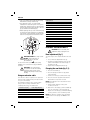
1
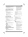
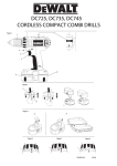
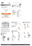
KOREAN
DWS520 PLUNGE SAW
축하드립니다!
귀하께서는 DEWALT 전동공구를 선택하셨습니다. 수년간의
경험과 완벽한 제품 개발, 혁신으로 DEWALT는 전문 전동공구
사용자에게 가장 믿을만한 동반자가 되었습니다.
기술데이터
DWS520
QS/GB
전압
VDC
220-240
소비전력
W
1300
무부하속도
min-1
1750-4000
톱날직경
min
165
최대 절삭 깊이
-90도(가이드레일 미사용시)
-90도(가이드레일 사용시)
mm
mm
59
톱날내경
mm
20
베벨각 조정
55
DWS520
QS/GB
LpA(음압)
dB(A)
92
KpA(음압 불확실성)
dB(A)
3
LWA(음향파워)
dB(A)
103
KWA(음향파워 불확실성)
dB(A)
3
EN60745에 따른 진동총합(triax 벡터합):
DWS520
불확실성 K = 1.5 m/s2
상기 진동 방출값은 표준시험 방법에 따라 측정했으며, 다른
전동공구와 비교하는데 이용할 수 있습니다.
또한 상기 진동 방출값은 진동에 대한 예비평가에 이용할 수도
있습니다.
경고 : 실제 사용시 진동 방출값은 전동공구를
사용하는 방법에 따라 다를 수 있습니다. 전동공구를
정해진 방법으로 정기적으로 사용할 때 진동을
확실히 낮게 추정할 수 있습니다.
47°
중량
kg
5
230V 공구
10 암페어, 주전선
230V 공구
13 암페어, 플러
진동 방출값 = 2.8 m/s2
퓨즈
유럽
정의: 안전 지침
아래 정의는 각 신호 단어에 대한 심각성의 정도를 설명하고
있습니다. 사용 설명서를 읽고 이 기호에 주의하여 주십시오.
위험 : 피하지 못한다면 그 결과가 사망이나 심각한
손상을 야기할 일촉즉발의 위험한 상황을 말합니다.
또한, 정해진 작업 기간에 경험한 진동에 대한 노출 정도는
전동공구의 스위치를 끌 때와, 방아쇠를 당기는 시간 외에도
공전일 때 각각의 값을 추정해야 합니다.
이로 인해 전체 작업 기간에 노출 정도를 확실히 줄여줄 수
있습니다.
EC-적합 선언
경고 : 피하지 못한다면 사망이나 심각한 손상을
야기할 가능성이 있는 위험한 상황을 말합니다.
주의 : 피하지 못한다면 경증 혹은 중등도의 손상을
야기할 가능성이 있는 위험한 상황을 말합니다.
주의 : 안전주의 기호 없이 기구를 사용하는 경우,
재산 손해를 야기할 가능성이 있는 위험한 상황을
말합니다.
감전의 위험을 나타냅니다.
화재 위험
DWS520
DEWALT는 “기술데이터”에 설명한 이 제품이 다음에 따라
고안되었음을 선언합니다.
2006/95/EC, 98/37/EC, 2004/108/EC ,
EN 60745-1, EN 60745-2-5, EN55014-1 : 2006,
EN 55014-2 : 1997 + A1 : 2001, EN 61000-3-2 : 2006, EN
61000-3-3 : 1995 + A1 : 2001
25
KOREAN
자세한 사항을 원하시면, 아래 주소나 본 설명서 후면을
참조하셔서 DEWALT에 연락해 주십시오.
공학 및 제품 개발 이사
Horst Grossmann
(4) 코드를 남용하지 마십시오. 전동공구를 옮길 때나
콘센트에서 플러그를 뽑을 때 코드를 절대 사용하지
마십시오. 열이나 기름, 날카로운 모서리, 움직이는
물체에 코드를 가까이 두지 마십시오.
코드가 손상되어 있으면 감전의 위험이 커집니다.
(5) 전동공구를 외부에서 사용할 때, 실외용 연장 코드를
사용하십시오. 실외용 코드를 사용하면 감전의 위험이
줄어듭니다.
DEWALT, Richard-Klinger-Strase 11,
D-65510, Idstein, Germany
2008년 8월 16일
경고 : 상해의 위험을 줄이도록, 본 사용설명서를
읽어주십시오.
일반 전동공구 안전 경고
경고 : 모든 안전 경고와 지침을 읽으십시오. 경고 및
지침을 따르지 않을 경우 감전이나 화재, 심각한
상해를 야기할 수 있습니다.
본 사용설명서를 보관하셔서 향후 참조하십시오.
제품을 사용하시기 전에 아래 모든 안전 수칙들을 읽고 보관
하십시오.
경고의“전동공구”라는 용어는 주전선(유선)을 연결한
전동공구나 배터리로 작동(무선)하는 전동공구를 말합니다.
(6) 불가피하게 전동공구를 축축한 곳에서 사용해야
한다면, 누전차단기(RCD)가 달린 전원공급장치를
이용하십시오. RCD를 사용하면 감전의 위험을
줄여줍니다.
3) 개인 안전
(1) 전동공구를 사용할 때는, 항상 주의를 기울이고, 하고
있는 작업을 똑바로 주시하며, 상식에 맞게 공구를
사용하십시오. 피곤한 상태이거나, 약물, 술 또는
의약품을 복용한 상태에서 전동공구를 사용하지
마십시오. 전동공구를 작동시키는 도중 주의하지 않을
경우, 심각한 부상을 입을 수도 있습니다.
(2) 안전 장비를 사용하십시오. 항상 보안경을
착용하십시오. 방진 마스크나 미끄럼 방지용 안전
신발, 견고한 헬멧, 귀마개 등의 안전 장비 사용으로
부상의 위험이 줄어듭니다.
(1) 작업 공간을 밝고 깨끗하게 유지하십시오. 산만하고
어두운 공간에서는 사고위험이 있습니다.
(3) 급작스런 시동을 하지
배터리 팩에 연결하기
옮기기 전에 스위치가
스위치에 손가락을 둔
옮기면 사고가 일어날
(2) 가연성 액체나 가스, 먼지 등이 있는 폭발성 대기에서는
전동공구를 작동하지 마십시오. 전동공구에서는
불꽃이 일어나 먼지나 연기를 발화할 수 있습니다.
(4) 공구를 켜기 전에 조정 키나 렌치를 제거하십시오.
기구의 순환 부분에 낄 수 있는 렌치나 조정키로
부상을 입을 수 있습니다.
(3) 전동공구를 작동하고 있는 동안 어린이나 구경꾼을
멀리 두십시오. 주의가 산만하면 전동공구를 통제하지
못할 수도 있습니다.
(5) 지나치게 사용하지 마십시오. 항상 알맞은 발판을 두고
균형을 유지하십시오. 이렇게 하면, 예상하지 못한
상황에서 기구를 잘 제어할 수 있게 합니다.
1) 작업공간 안전
2) 전기 안전
(1) 전동공구 플러그를 콘센트에 맞춰서 사용해야 합니다.
어떤 방법으로든 플러그를 절대 변형하지 마십시오.
접지된 전동공구에 어댑터를 사용하지 마십시오.
플러그를 변형하지 않고, 콘센트에 맞춰서 사용하면
감전의 위험이 줄어들 것입니다.
(2) 파이프나 라디에이터, 렌지나 냉장고 등 접지된 표면에
몸을 접촉하지 마십시오. 신체가 접지되면 감전의
위험이 커집니다.
(3) 전동공구를 비나 젖은 곳에 노출하지 마십시오.
전동공구에 물이 들어가면 감전의 위험이 커질 수
있습니다.
26
마십시오. 전원공급장치나
전에, 전동공구를 들어올리거나
꺼져 있음을 확인하십시오.
채 공구에 전원을 연결하거나
수 있습니다.
(6) 적절한 의복을 입으십시오. 늘어진 옷이나 장신구를
착용하지 마십시오. 머리카락과 옷, 장갑을 기구의
구동부위에서 멀리 두십시오. 늘어진 옷이나 장신구,
긴 머리카락은 구동부위에 낄 수 있습니다.
(7) 먼지 추출이나 수집 시설에 연결하는 장비가 있을
경우, 연결되었는지, 제대로 사용되고 있는지
확인하십시오. 이러한 장비를 사용하여 먼지와 관련된
위험을 줄일 수 있습니다.
4) 전공공구의 사용 및 관리
(1) 전동공구에 무리한 힘을 주지 마십시오. 용도에 맞는
공구를 사용하십시오. 적절한 공구를 사용하면 신속하고
안전하게 작업할 수 있습니다.
KOREAN
(2) 전원스위치가 작동하지 않으면 공구를 사용하지
마십시오. 스위치가 불량한 공구는 위험하므로 반드시
수리해야 합니다.
(3) 전동공구의 조절장치 설정을 변경하거나, 부속품을
교환하거나, 보관하기 전에 전원에서 플러그를 뽑아야
합니다. 이러한 예방 안전법을 준수하면 예상치 못한
공구의 시동 위험이 감소합니다.
(4) 사용하지 않는 전동공구는 어린이나 숙련되지 않은
사람의 손이 닿지 않는 곳에 보관하십시오. 숙련되지
않은 사용자가 전동공구를 사용하기에는 위험합니다.
(5) 전동공구를 관리하십시오. 조정 불량이나 구동 부위의
박힘, 부속의 파손이나 전동공구 작동에 영향을 줄 수
있는 기타 상태를 확인하십시오. 손상되었다면,
사용하기 전에 수리하셔야 합니다. 정비가 불량하면
많은 사고가 발생합니다.
(6) 절삭도구를 날카롭고 깨끗하게 하십시오. 날카롭게 잘
정비한 절삭도구는 작업 대상물에 잘 박히지 않고,
통제하기 쉽습니다.
(7) 작업 상태나 수행할 작업을 고려하여, 본 지시사항에
따라 특정 용도로 전동공구 및 부속품, 기구 비트를
사용하십시오. 사용 목적에 맞지 않는 전동공구를
사용하면 위험에 처할 수 있습니다.
5) 서비스
(1) 동일한 교체 부품을 이용하는 유자격 수리공에게
전동공구 서비스를 받으십시오. 전동공구의 안전한
관리를 보장받으실 수 있습니다.
부가적인 특별 안전 수칙
모든 톱에 관한 안전 수칙
(1)
경고 : 절단 부위나 톱날에 손을 가까이 두지
마십시오. 간접적으로 손을 보조 핸들이나 모터하우징에
두십시오. 만약 양 손으로 톱을 잡고 있으면, 톱날에
의해 잘릴 수 없습니다.
(2) 작업 대상물 아래에 가지 마십시오. 작업대상물 아래에서
가드로 사용자를 톱날에서 보호할 수 없습니다.
(3) 작업 대상물의 두께에 절삭 깊이를 조정하십시오. 작업
대상물 아래 톱니의 모든 니보다 적은 니가 보여야
합니다.
(4) 자를 부분을 손이나 다리로 절대 붙잡지 마십시오.
작업 대상물을 안정한 곳에 두십시오. 이는 신체 노출,
톱날 박힘, 제어불능 등을 최소화하여 제대로 작업을
할 수 있도록 하기 위해 중요합니다.
(5) 절단공구가 숨어있는 전선에 닿을 수 있는 곳에서
작업을 할 때 절연된 손잡이 표면으로 전동공구를
잡으십시오.“전류가 흐르는”전선에 접촉하게 되면
전동공구의 노출된 금속부위에도“전류가 흐르”게
되므로 작동자가 감전될 수 있습니다.
(6) 세로켜기를 할 때에는 조기대나 스트레이트 엣지
가이드를 항상 사용하십시오. 그렇게 하면, 보다
정확하게 절단할 수 있고 톱날이 박힐 기회가
줄어듭니다.
(7) 항상 아버 구멍이 알맞은 크기와 형태(다이아몬드형
vs 원형)의 톱날을 사용하십시오. 톱의 고정 부분과
맞지 않는 톱날은 편심적으로 작동하여 통제 불능이
될 수 있습니다.
(8) 손상되거나 맞지 않는 톱날 워셔나 볼트를 절대
사용하지 마십시오. 최적의 성능과 작동시의 안전을
위해 톱날 워셔와 볼트는 톱에 맞게 특별히
고안되었습니다.
반동의 원인과 작동자 예방법
- 끼어있거나 박혀있거나 조정 불량의 톱날에는 갑자기
반동이 일어나 톱날이 들어올려지거나 작동자를 향해
작업 대상물 밖으로 나오게 됩니다.
- 톱날이 아래쪽으로 켠 자국에 단단히 끼어있거나
박혀있을 때에는 톱날은 시간을 지연시키고, 모터는
재빨리 작동자를 향해 작동합니다.
- 톱날이 꼬여있거나 조정이 불량하게 된다면, 톱날의 뒤쪽
가장자리 톱니는 목재 표면을 파고 들어가 톱날이 그 켠
조각 위로 올라 작동자를 향해 튀어 오르게 됩니다.
반동은 톱날을 잘못 사용하거나 잘못된 작동 과정 혹은 상태로
인해 발생하며, 다음과 같이 적절히 주의하면 이를 피할 수
있습니다.
(1) 반동력에 대항하여 톱의 손잡이를 양손으로 확실히
잡고 팔을 제 위치에 두십시오. 신체를 톱날의 한 쪽에
두고, 톱날과 일렬로 있지 마십시오. 반동으로 톱날이
뒤쪽으로 튀어오를 수 있지만 주의하면 작동자가
반동력을 제어할 수 있습니다.
27
KOREAN
(2) 톱날이 박힐 때나 어떤 이유로 절단이 방해될 때에는
방아쇠를 놓고 톱날이 완전히 멈출 때까지 재료 위에
톱날이 움직이지 않을 때까지 붙잡고 계십시오. 톱날이
움직이거나 반동이 일어날 수 있는 동안 톱날을
제거하거나 톱을 뒤로 잡아당기지 마십시오. 톱날이
박히지 않도록 연구하고, 올바른 행동을 취하십시오.
(3) 작업 대상물에서 톱을 재가동 할 때, 톱날이 켠 자국의
중앙에 오도록 하고, 톱니가 재료에 제대로 맞는지
확인하십시오. 톱날이 박혀있다면, 톱을 재가동 하면서
그대로 작동하거나 반동이 생길 수 있습니다.
(4) 톱날이 끼거나 반동이 생길 위험을 최소화하도록 큰
패널을 지지하십시오. 큰 패널은 그 무게 때문에 중간이
휘는 경향이 있습니다. 절단 선 가까이, 판넬의 가장자리
가까이 판넬의 양 면 아래를 지지해 주십시오.
(5) 무디거나 손상된 톱날을 사용하지 마십시오. 무디거나
부적절한 톱날로 협소하게 켜게 되어 과도한 마찰이나
톱날 박힘, 반동을 야기하게 됩니다.
(6) 톱날 깊이와 베벨조절 잠금레버는 조여져 있어야 하며
절단하기 전에 이를 확인하십시오. 톱날 조정장치가
작동 중에 움직이면, 박히거나 반동이 생길 수
있습니다.
(7) 기존의 벽이나 다른 보이지 않는 곳에서 “플런지
컷”을 할 때에 특별히 주의하십시오. 돌출된 톱은
반동을 야기할 수 있는 물체를 자를 수 있습니다.
(3) 베벨각이 90°가 아닌 상태에서 “플런지컷”을 하는
동안 톱의 가드플레이트가 움직이지 않는지
확인하십시오. 톱날이 옆으로 이동하면 박히거나
반동이 일어날 것입니다.
(4) 톱을 작업대나 바닥에 내려놓기 전에 가드가 톱날을
덮고 있는지 항상 살펴보십시오. 톱날이 노출되어
있는 상태에서 움직이면 톱은 뒤로 움직여 그 경로에
있는 무엇이든 절단할 수 있습니다. 스위치를 놓은
후에는 톱날이 멈추는데 걸리는 시간을 알아두십시오.
라이빙 나이프가 있는 모든 톱에
대한 부가적인 안전 수칙
(1) 사용할 톱날에 맞는 라이빙 나이프를 사용하십시오.
사용할 라이빙 나이프는 톱날 보다는 두껍지만,
톱니보다는 얇아야 합니다.
(2) 본 사용설명서에서 설명한 바대로 라이빙 나이프를
조정하십시오. 올바르지 못한 위치나 배열을 하면
라이빙 나이프가 반동을 예방하는데 효과적일 수
없습니다.
(3) 사용할 라이빙 나이프를 작업 대상물에 맞물리게 해야
합니다. 라이빙 나이프는 짧은 절단을 하는 동안
반동을 예방하는데 효과적이지 않습니다.
(4) 라이비 나이프가 휘어 있다면 톱을 작동하지 마십시오.
빛의 간섭으로 가드가 내려오는 속도가 늦어질 수
있습니다.
플런지 형태의 톱에 대한 부가적인
안전 수칙
플런지 형태의 톱에 대한 안전 지침
• 귀마개를 착용하십시오. 소음에 노출되면 청력을 잃을
수 있습니다.
• 방진 마스크를 착용하십시오. 먼지 입자에 노출되면
(1) 매번 사용 전에 가드가 제대로 닫혀있는지 확인하십시오.
가드가 제대로 움직이지 않거나 톱날을 즉시 감싸지
않는다면 톱을 작동하지 마십시오. 노출된 톱날과
가드를 절대 조이지 마십시오. 톱을 우발적으로
떨어뜨리면, 가드가 휘어질 수 있습니다. 가드가 제대로
움직이는지, 모든 각도와 절단 깊이에서 톱날이나 기타
다른 부분을 건드리지 않는지 확인하십시오.
(2) 가드리턴스프링의 작동과 상태를 살펴보십시오. 가드와
스프링이 제대로 작동하지 않는다면, 사용 전에 수리를
받아야 합니다. 손상된 부위, 점착성 침전물 혹은
찌꺼기로 인해 둔하게 작동할 수 있습니다.
28
호흡 곤란이나 상해를 입을 수 있습니다.
• 권장한 것보다 크거나 작은 직경의 톱날을 사용하지
마십시오. 기술 데이터를 참고하여 적절한 톱날을
사용하십시오. EN847-1에 따라 본 설명서에서 정한
톱날만을 사용하십시오.
• 부식성 절단 휠을 절대 사용하지 마십시오.
잔존 위험
• 관련 안전 규정을 적용하고, 안전 장치를 사용해도
피할 수 있는 위험이 있습니다.
KOREAN
–
청력 장애
e. 베벨 조절 노브
–
회전하고 있는 절단 디스크의 가려지지 않은 부위에
의해 야기되는 사고 위험
f. 깊이 조절 노브
디스크를 바꿀 때 다칠 위험
절단할 때 위험할 수 있는 재료의 먼지 흡입 위험
h. 앞 손잡이
–
g. 깊이 눈금
i. 먼지 배출구
j. 레일 조정기
전동공구의 표시
본 사용설명서에서 사용하는 그림 외에, 전동공구에는 다음과
같은 표시가 있습니다.
k. 톱날
l. 잠금 버튼
m. 잠금 레버
n. 톱날 클램프 나사
최대 절단 깊이
o. 외부 플랜지
p. 내부 플랜지
톱날 직경
q. 라이빙 나이프
r. 라이빙 나이프 조절 나사
포장내용
s. 속도 휠
t. 절단 표시기
플런지쏘 1
u. 반동 방지 노브
레일 클램프 1
v. 외부 가드
알렌 키 1
w. 가이드 레일
사용설명서 1
x. 클램프
기계 부품 도안 1
y. 톱날 위치 표시기
• 배송 시 생길 수 있는 전동기구나 부품, 부속품의 손상을
확인하십시오.
포장내용
• 작동하기 전에 본 사용 설명서를 철저히 읽고 이해하십시오. 전기 모터는 한 가지 전압에만 사용할 수 있습니다.
계기판에서 전원 공급장치가 전압에 맞는지 항상 확인하십시오.
설명(Fig 1,-3)
DEWALT 전동기구는 EN 60745에 따라 이중으로
절연되어 있습니다. 그러므로 피뢰선이 필요하지
않습니다.
코드가 손상되었다면 코드를 교체하는 경우, 전동기구는 지정
서비스 센터나 기사에게 수리를 받아야 합니다.
용도
DWS520 플런지쏘는 전문 톱질이나 목재 제품 절단을 위해
고안되었습니다.
젖은 상태에서나 가연성 액체 혹은 기체가 있는 곳에서
사용하지 마십시오.
강력한 플런지쏘는 전문 전동공구입니다. 어린아이들이 가까이
하지 않도록 하십시오. 경험이 없는 작동자가 이 공구를 사용할
때에는 감독을 해야 합니다.
a. 플런지 방아쇠
b. 전원 스위치
c. 손잡이
d. 슈
주 플러그 교체(U.K.와 아일랜드)
위험 : 주 플러그를 교체해야 하고 귀하가 이를 할
수 있다면, 다음 지침대로 따르십시오. 그렇지 않을
경우, 지정 DEWALT 서비스 센터나 기사에게
연락하십시오.
• 전원 공급 장치에서 플러그를 제거하십시오.
• 플러그를 절단하고 안전하게 이를 처리하십시오.
벗겨진 구리 도선이 있는 플러그는 전원이 있는 곳에
접촉하면 위험합니다.
• 13A BS1363A 플러그를 적합한 퓨즈에 맞추십시오.
29
KOREAN
• 케이블 선의 색 혹은 글자는 가장 질 좋은 플러그의
연결 부위에 표시될 것입니다. 이 선들을 플러그의 해당
부위에(아래 참조) 놓습니다. 갈색은 Live(L)(2),
파란색은 Neutral(N)(4)입니다.
• 주 플러그의 맨 위 뚜껑을 교체하기 전에 케이블
리스트레인트(3)을 케이블의 바깥쪽에 확실히
고정했는지, 두 선이 끝에 제대로 고정되었는지
확인하십시오.
1
2
4
케이블 길이(m)
7.5
전압
전류
15
25
30
45
60
6
6
6
6
15 20
20 20
25 25
–
–
6
6
6
6
6
10
10 15
15 20
20 25
10
15
20
25
–
–
6
6
15
15
20
–
케이블 속도(암페어)
115
0 – 2.0
2.1 – 3.4
3.5 – 5.0
5.1 – 7.0
7.1 – 12.0
12.1 – 20.0
230
0 – 2.0
2.1 – 3.4
3.5 – 5.0
5.1 – 7.0
7.1 – 12.0
12.1 – 20.0
6
6
6
10
15
20
6
6
6
10
15
20
6
6
6
10
15
20
6
6
6
10
15
20
6
6
10
15
20
25
6
6
6
10
15
20
조립 및 조정
3
경고 : 조립이나 조정 전에, 항상 전원을
연결하지 마십시오.
베벨 조정 (그림 1)
베벨각은 0°와 47°사이로 조정할 수 있습니다.
경고 : 절대 전구 소켓을 사용하지 마십시오.
E 나
로 표시된 접지핀에 live(L)이나
neutral(N)을 절대 연결하지 마십시오.
1500W를 초과하는 경우 115V를 사용해야 할 때, BS4343
표준에 맞는 플러그를 권장합니다.
경고 : 115V 공구는 1차와 2차 와인딩 사이에
접지 스크린으로 고장안전 전리 변압기를 통해
작동해야 합니다.
1. 베벨 조절 노브(e)를 풀어줍니다.
2. 깊이 눈금(g)을 원하는 각도로 맞출 때까지 톱 슈(d)를
경사지게 하여 베벨 각을 설정합니다.
3. 베벨 조절 노브(e)를 조여줍니다.
톱날 교환하기 (그림 2,3)
1. 잠금 버튼(I)를 누르십시오.
2. 멈추도록 플는지쏘를 아래로 누르십시오. (톱날 변화 위치)
연장케이블 사용
3. 잠금 레버(m)를 멈출 때까지 시계방향으로 돌리십시오.
연장케이블이 필요하다면 본 전동기구의 전원에 맞는 연장케이블을
사용하십시오(기술 데이터 참조).
최소 도체 크기는 1.5mm2입니다. 케이블릴 사용시, 케이블을
완전히 풀어주십시오. 그리고 아래 표를 참조하십시오.
30
도체 크기(mm2)
케이블 속도(암페어)
0.75
1.00
1.50
2.50
4.00
6
10
15
20
25
4. 잠금 레버(m)을 아래로 누르고 잠금 위치를 찾을 때까지
톱날을 돌리십시오.
주의 : 톱날(k)는 이제 고정되어 있으며, 손으로 돌릴 수 없습니다.
5. 톱날 클램핑 나사(n)를 시계 반대방향으로 돌려 제거하십시오.
6. 외부 플랜지(o)와 사용한 톱날(k)를 제거하십시오.
새로운 톱날을 내부 플랜지(p)에 두십시오.
7. 외부 플랜지(o)와 톱날 클램핑 나사(n)을 다시 조이십시오.
손으로 나사를 시계방향으로 돌리십시오.
주의 : 톱날의 회전 방향과 플런지쏘의 회전방향은 반드시
같아야 합니다.
KOREAN
8. 알렌키를 사용하여 톱날 클램핑 나사를 확실히 조여주십시오.
• 항상 기기를 앞으로 미십시오. 절대 작동자를
향하여 기기를 뒤로 밀지 마십시오.
9. 잠금 레버(m)를 멈출 때까지 시계 반대방향으로 돌리십시오.
• 항상 양손으로 플런지쏘를 사용하십시오. 한
10. 플런지쏘를 위로 향하게 하십시오.
손으로 주손잡이(C)를 잡고 다른 손으로 앞
손잡이(h)를 그림 5와 같이 잡으십시오.
11. 플런지 방아쇠(a)를 앞으로 눌러 교환한 톱날을 고정하십시오.
라이빙 나이프 조정하기 (그림 3)
• 항상 그림 6과 같이 작업 대상물에 레일을
라이빙 나이프(q)를 제대로 조정하려면, 그림 3을 참고하십시오.
톱날을 교환하거나 필요할 때는 언제든지 라이빙 나이프의
틈을 조정하십시오.
• 코드가 톱날의 경로에 있지 않도록
고정하도록 클램프를 사용하십시오.
확인하십시오.
1. 톱날 교환하기 1-4를 따르십시오.
• 톱이 제대로 가도록 주손잡이(c)와 앞손잡이(h)로
2. 라이빙 조절 나사(r)을 알렌키로 풀고 그림 3과 같이
라이빙 나이프를 놓습니다.
• 절단 표시기(t)가 0°~ 47°의 절단 선을 보여줍니다.
3. 라이빙 나이프 나사(r)를 조이십시오.
4. 잠금 레버(m)을 멈출 때까지 시계 반대방향으로
돌리십시오.
5. 플런지쏘를 위로 향하게 하십시오.
절삭 깊이 조절 (그림 4)
가이드 레일을 사용하지 않으면 절삭 깊이는 0-59mm로
설정할 수 있습니다. 가이드 레일을 사용하면 0-55mm로
설정할 수 있습니다.
1. 깊이 조절 노브(f)를 풀고 알맞은 절삭 깊이에 오도록
지침을 움직입니다.
2. 깊이 조절 노브(f)를 조이십시오.
주의 : 최적의 결과를 위해, 톱날이 작업대상물에서 약 3mm정도
튀어나오도록 하십시오(그림 4).
작동
경고 : 플런지쏘를 사용하기 전에, 항상 모든
기능이 제대로 되는지 확인하십시오.
사용 설명
전동공구를 잡으십시오.
(가이드 레일 미사용시).
• 톱날 위치 표시기(y)는 전체 플런지 과정에서 톱날의
위치를 보여줍니다.
• 최적의 결과를 위해, 작업 대상물을 뒤집어 고정하십시오.
절단
1. 톱 베이스를 앞쪽으로 하여 작업 대상물 위에
전동공구를 두십시오.
2. 전원 스위치를 눌러 톱을 작동하십시오.
3. 플런지 스위치(a)를 앞으로 밀어 절삭 깊이를
설정하도록 톱을 아래로 누르고, 절단 방향으로
밀어주십시오.
플런지컷
경고 : 반동을 피하도록, 플런지컷을 할 때 다음
지침을 반드시 준수하십시오.
• 전동공구를 가이드 레일 위에 놓고, 반동 방지
노브(u)를 시계 반대방향으로 돌려서
풀어주십시오.
• 전동공구의 전원을 켜고 천천히 톱을 설정한
경고 : 항상 안전 지침과 적용 법규를
준수하십시오.
스위치 on/off (그림 1)
플런지쏘를 켜려면 전원 스위치를 누르십시오.
전동공구를 잡는 방법 및 사용 방법
(그림 5,6)
경고
• 항상 톱질을 하는 동안 작업 대상물이
움직이지 않도록 하십시오.
절단 깊이만큼 아래로 누르고 절단 방향으로
밀어주십시오. 절단 표시기(t)는 최대 절삭
깊이에서 가이드 레일을 이용하여 톱날의
전적으로 앞쪽과 뒤쪽의 절단 지점을
보여줍니다. (직경 165 mm).
• 플런지컷을 하면서 반동이 일어나면, 반동
방지 노브(u)를 시계반대방향으로 돌려
레일에서 풀어주십시오.
• 플런지컷을 마쳤을 때에는 반동 방지 노브(u)를
시계방향으로 돌려 잠금위치에 두십시오.
31
KOREAN
가이드 시스템 (그림 1,5)
재료 종류
속도 범위
여러가지 길이의 가이드 레일은 명확하고 깨끗하게 절단을
하도록 해주며, 동시에 작업 대상물 표면이 손상되지 않도록
보호해줍니다.
원목(딱딱하거나 부드러운)
5
칩보드, 경질섬유보드
2-5
적층 목재, 합판, 베니어판, 광택판지
5
플라스틱, 섬유강화 플라스틱, 종이 및 천
2-3
아크릴 유리
2-3
추가의 부속품을 사용하여, 가이드 레일 시스템으로 정확한
각도의 컷이나, 회전 컷이나 맞춤 작업 등을 할 수 있습니다.
작업 대상물을 클램프로 고정하면 안전하게 작업을 할 수
있습니다.
최고의 결과를 얻으려면 플런지쏘의 가이드 틈은 매우 작아야
하며, 두 개의 레일 조절장치(j)로 설정할 수 있습니다.
1. 레일 조절장치 내부의 나사를 풀어 틈을 조절합니다.
2. 레일에 톱을 고정할 때까지 노브를 조정합니다.
3. 톱이 쉽게 미끌어질때까지 노브를 다시 돌려줍니다.
4. 레일 조절장치를 제 위치에 놓고 나사로 다시 고정합니다.
주의 : 항상 다른 레일을 사용할 때에는 이 시스템을 다시
조절하십시오.
문 절단 (그림 7)
1. 외부 가드(v)로 플런지쏘를 깨끗하고 평평한 바닥에
놓으십시오.
2. 조절한 깊이에 올 때까지 앞 쪽의 슈(d)를 문 위로
누르십시오.
먼지 집진 (그림 1)
본 전동공구에는 먼지배출구(i)가 있습니다.
경고 : 항상 플런지쏘를 먼지 집진기에
연결하십시오.
스플린터가드
경고 : 먼지 방출에 관한 관련 법령에 따라
고안한 먼지 집진 장치를 항상
사용하십시오.
이 가이드 레일은 처음 사용하기 전에 크기에 맞게 자르도록
스플린터가드에 장치되어 있습니다.
주의 : 항상 스플린터가드를 절단하기 전에 가이드시스템
지침을 읽고 따르십시오.
1. 레벨 5로 플런지쏘의 속도를 설정하십시오.
관리
최소한의 관리로 DEWALT 전동공구를 오랫동안 사용하실 수
있도록 고안했습니다. 지속적인 안전 작동을 위해서는 적절한
도구 관리와 규칙적인 세척이 필요합니다.
2. 가이드 레일을 목재 조각에 두십시오.
3. 플런지쏘를 5mm 절삭깊이로 설정하십시오.
4. 가이드 레일의 뒤쪽 끝 부분에 톱을 두십시오.
5. 톱을 켜고 설정한 절삭 깊이 대로 눌러 한번에 원하는
길이로 스플린터가드를 자르십시오. 스플린터가드의
가장자리는 이제 톱의 절단 가장자리와 정확하게
일치합니다.
경고 : 다칠 위험을 줄어기 위해, 가이드레일
(w)을 클램프(x)로 항상 고정하십시오.
속도 조절 (그림 1)
속도는 속도 휠(s)을 이용하여 1750-4000/min로 조절할 수
있습니다. 이 때문에 재료에 맞는 절단 속도를 설정할 수
있습니다. 재료의 종류와 속도 범위에 대한 다음 표를
참고하십시오.
32
경고 : 상해 위험을 줄이려면, 설치나 부속품
제거, 설정 조정 및 변경, 수리하기 전에
전동공구를 끄고 전원을 연결하지 마십시오.
스위치가 OFF에 있음을 확인하십시오.
우발적인 시동으로 상해를 입을 수
있습니다.
경고 : 톱날이 무뎌지면 새로운 날카로운
톱날로 교체하십시오.
윤활처리
전체적으로 폐쇄형 그리스 봉합 볼 베어링이 사용되었습니다.
이 베어링은 지속적인 톱의 수명을 위해 공장에서 충분히
윤활처리가 되었습니다.
KOREAN
새 제품을 구매할 때 지방 자치 폐기장이나 판매점에서는
가정의 전기제품 분리수거에 대한 지역 규제 조항을
알려드립니다.
윤활처리
경고 : 때가 끼거나 급기관 주변이 더러워지면
메인 하우징에서 때와 먼지를 건조한 바람으로
제거하십시오. 이를 행할 시, 보안경과 방진
마스크를 사용하십시오.
경고 : 전동공구의 비금속 부분을 세척할 때
용매나 강력한 화학 물질을 사용하지 마십시오.
이 화학물질은 이 부위에 사용한 재료를
손상시킬 수 있습니다. 물과 약한 비누로 적신
천을 이용하십시오. 전동공구 내부에 물이
들어가지 않도록 하십시오. 전동공구의 어느
부분이든 액체에 담그지 마십시오.
DEWALT에는 작업 수명이 끝날 때 이를 수거하고 재활용하는
공장이 있습니다. 이 서비스를 받으시려면, 이를 수거할 귀사
서비스센터에 제품을 반환해주십시오.
본 사용 설명서에 있는 주소로 지역 DEWALT 사무실에
연락하시면 가장 가까운 서비스 센터의 위치를 확인하실 수
있습니다. 혹은, www.2helpU.com에서 DEWALT 서비스 센터
목록과 애프터서비스와 연락처에 관한 모든 사항을 보실 수
있습니다.
선택 부속품
경고 : 전동공구의 비금속 부분을 세척할 때
용매나 강력한 화학 물질을 사용하지 마십시오.
이 화학물질은 이 부위에 사용한 재료를
손상시킬 수 있습니다. 물과 약한 비누로 적신
천을 이용하십시오. 전동공구 내부에 물이
들어가지 않도록 하십시오. 전동공구의 어느
부분이든 액체에 담그지 마십시오.
DEWALT는 플런지쏘에 맞는 톱날을 제공합니다. 적절한 부속품에
관한 사항을 알고 싶으시면 판매자에게 문의하십시오.
환경 보호
분리수거 하십시오. 본 제품은 일반 쓰레기와
함께 버리지 마십시오.
DEWALT제품을 교체해야 하거나, 더 이상 사용하지 않으실 경우,
일반 쓰레기와 함께 버리지 마십시오. 분리 수거가 가능하게
하십시오.
사용한 제품을 분리수거 및 포장하면 재료를
재활용할 수 있게 됩니다. 재활용품의
재사용으로 환경오염을 예방하고, 원료 수요를
줄여주는데 도움이 됩니다.
33
ENGLISH
DWS520 PLUNGE SAW
Congratulations!
You have chosen a DEWALT tool. Years of
experience, thorough product development and
innovation make DEWALT one of the most reliable
partners for professional power tool users.
Technical data
Voltage
Power
No-load speed
Blade diameter
Maximum depth of cut
90˚ (without guide rail)
90˚ (with guide rail)
Blade bore
Bevel angle adjustment
Weight
Fuses:
Europe
U.K. & Ireland
VDC
W
min-1
mm
mm
mm
mm
kg
230 V tools
230 V tools
DWS520
DWS520
QS/GB
LX
220-240
115
1300
1300
1750-4000 1750-4000
165
165
59
55
20
47˚
5
59
55
20
47˚
5
10 Amperes, mains
13 Amperes, in plugs
Definitions: Safety Guidelines
The definitions below describe the level of severity
for each signal word. Please read the manual and
pay attention to these symbols.
DANGER: Indicates an imminently
hazardous situation which, if not avoided,
will result in death or serious injury.
WARNING: Indicates a potentially
hazardous situation which, if not
avoided, could result in death or
serious injury.
CAUTION: Indicates a potentially
hazardous situation which, if not
avoided, may result in minor or
moderate injury.
CAUTION: Used without the safety alert
symbol indicates a potentially hazardous
situation which, if not avoided, may
result in property damage.
Denotes risk of electric shock.
Denotes risk of fire.
LpA (sound pressure)
KpA (sound pressure uncertainty)
LWA (acoustic power)
KWA (acoustic power uncertainty)
dB(A
dB(A)
dB(A)
dB(A)
DWS520
QS/GB
92
3
103
3
DWS520
LX
92
3
103
3
Vibration total values (triax vector sum)
determined according to EN 60745:
DWS520
Vibration emission value = 2.8 m/s²
Uncertainty K = 1.5 m/s²
The declared vibration emission value has been
measured in accordance with a standard test
method and may be used for comparing one tool
with another.
The declared vibration emission value may also be
used in a preliminary assessment of exposure.
WARNING: The vibration emission
value during actual use of the power
tool can differ from the declared value
depending on the ways in which the tool
is used. This could lead to a significant
underestimate of exposure when the
tool is used regularly in such a way.
An estimation of the level of exposure to vibration
experienced during a given period of work should
also take into account the times when the tool is
switched off and when it is running idle in addition to
the trigger time.
This may significantly reduce the exposure level over
the total working period.
EC-Declaration of conformity
DWS520
DEWALT declares that these tools have been
designed in compliance with:
2006/95/EC, 98/37/EC, 2004/108/EC,
EN 60745-1, EN 60745-2-5, EN 55014-1: 2006,
EN 55014-2:1997 + A1:2001, EN 61000-3-2: 2006,
EN 61000-3-3: 1995 + A1: 2001.
25
EN GLI S H
For more information, please contact DEWALT at the
address below, or refer to the back of the manual.
Director Engineering and Product Development
Horst Grossmann
e)
f)
DEWALT, Richard-Klinger-Strase 11,
D-65510, Idstein, Germany
16/08/2007
WARNING: To reduce the risk of injury,
read the instruction manual.
General Power Tool Safety Warnings
WARNING! Read all safety warnings
and instructions Failure to follow the
warnings and instructions may result in
electric shock, fire and/or serious injury.
SAVE ALL WARNINGS AND INSTRUCTIONS
FOR FUTURE REFERENCE.
The term “power tool” in the warnings refers to your
mains-operated (corded) power tool or batteryoperated (cordless) power tool.
1) WORK AREA SAFETY
a) Keep work area clean and well lit.
Cluttered or dark areas invite accidents.
b) Do not operate power tools in explosive
atmospheres, such as in the presence of
flammable liquids, gases or dust. Power
tools create sparks which may ignite the dust
or fumes.
c) Keep children and bystanders away while
operating a power tool. Distractions can
cause you to lose control.
2) ELECTRICAL SAFETY
a) Power tool plugs must match the outlet.
Never modify the plug in any way. Do
not use any adapter plugs with earthed
(grounded) power tools. Unmodified plugs
and matching outlets will reduce risk of
electric shock.
b) Avoid body contact with earthed or
grounded surfaces such as pipes,
radiators, ranges and refrigerators. There
is an increased risk of electric shock if your
body is earthed or grounded.
c) Do not expose power tools to rain or wet
conditions. Water entering a power tool will
increase the risk of electric shock.
d) Do not abuse the cord. Never use the
cord for carrying, pulling or unplugging
the power tool. Keep cord away from
26
heat, oil, sharp edges or moving parts.
Damaged or entangled cords increase the
risk of electric shock.
When operating a power tool outdoors,
use an extension cord suitable for outdoor
use. Use of a cord suitable for outdoor use
reduces the risk of electric shock.
If operating a power tool in a damp
location is unavoidable, use a residual
current device (RCD) protected supply.
Use of an RCD reduces the risk of electric
shock.
3) PERSONAL SAFETY
a) Stay alert, watch what you are doing and
use common sense when operating a
power tool. Do not use a power tool while
you are tired or under the influence of
drugs, alcohol or medication. A moment of
inattention while operating power tools may
result in serious personal injury.
b) Use personal protective equipment.
Always wear eye protection. Protective
equipment such as dust mask, non-skid
safety shoes, hard hat, or hearing protection
used for appropriate conditions will reduce
personal injuries.
c) Prevent unintentional starting. Ensure
the switch is in the off position before
connecting to power source and/or
battery pack, picking up or carrying the
tool. Carrying power tools with your finger
on the switch or energising power tools that
have the switch on invites accidents.
d) Remove any adjusting key or wrench
before turning the power tool on. A
wrench or a key left attached to a rotating
part of the power tool may result in personal
injury.
e) Do not overreach. Keep proper
footing and balance at all times. This
enables better control of the power tool in
unexpected situations.
f) Dress properly. Do not wear loose
clothing or jewellery. Keep your hair,
clothing and gloves away from moving
parts. Loose clothes, jewellery or long hair
can be caught in moving parts.
g) If devices are provided for the connection
of dust extraction and collection facilities,
ensure these are connected and properly
used. Use of dust collection can reduce
dust-related hazards.
4) POWER TOOL USE AND CARE
a) Do not force the power tool. Use the
correct power tool for your application.
The correct power tool will do the job
ENGLISH
b)
c)
d)
e)
f)
g)
better and safer at the rate for which it
was designed.
Do not use the power tool if the switch
does not turn it on and off. Any power
tool that cannot be controlled with the switch
is dangerous and must be repaired.
Disconnect the plug from the power
source and/or the battery pack from
the power tool before making any
adjustments, changing accessories, or
storing power tools. Such preventive safety
measures reduce the risk of starting the
power tool accidentally.
Store idle power tools out of the reach
of children and do not allow persons
unfamiliar with the power tool or these
instructions to operate the power tool.
Power tools are dangerous in the hands of
untrained users.
Maintain power tools. Check for
misalignment or binding of moving parts,
breakage of parts and any other condition
that may affect the power tool’s operation.
If damaged, have the power tool repaired
before use. Many accidents are caused by
poorly maintained power tools.
Keep cutting tools sharp and clean.
Properly maintained cutting tools with sharp
cutting edges are less likely to bind and are
easier to control.
Use the power tool, accessories and
tool bits etc., in accordance with these
instructions taking into account the
working conditions and the work to
be performed. Use of the power tool for
operations different from those intended
could result in a hazardous situation.
5) SERVICE
a) Have your power tool serviced by a
qualified repair person using only identical
replacement parts. This will ensure that the
safety of the power tool is maintained.
ADDITIONAL SPECIFIC SAFETY RULES
Safety instructions for all saws
a)
b)
DANGER: Keep hands away from
cutting area and the blade. Keep your
second hand on auxiliary handle, or motor
housing. If both hands are holding the saw,
they cannot be cut by the blade.
Do not reach underneath the workpiece.
The guard cannot protect you from the blade
below the workpiece.
c)
d)
e)
f)
g)
h)
Adjust the cutting depth to the thickness
of the workpiece. Less than a full tooth of
the blade teeth should be visible below the
workpiece.
Never hold piece being cut in your hands
or across your leg. Secure the workpiece
to a stable platform. It is important to
support the work properly to minimize body
exposure, blade binding, or loss of control.
Hold power tool by insulated gripping
surfaces when performing an operation
where the cutting tool may contact hidden
wiring. Contact with a "live" wire will also
make exposed metal parts of the power tool
"live" and shock the operator.
When ripping always use a rip fence or
straight edge guide. This improves the
accuracy of cut and reduces the chance of
blade binding.
Always use blades with correct size
and shape (diamond versus round) of
arbour holes. Blades that do not match
the mounting hardware of the saw will run
eccentrically, causing loss of control.
Never use damaged or incorrect blade
washers or bolt. The blade washers and
bolt were specially designed for your saw,
for optimum performance and safety of
operation.
Causes and Operator Prevention
of Kickback
– Kickback is a sudden reaction to a pinched,
bound or misaligned saw blade, causing an
uncontrolled saw to lift up and out of the
workpiece toward the operator;
– When the blade is pinched or bound tightly
by the kerf closing down, the blade stalls and
the motor reaction drives the unit rapidly back
toward the operator;
– If the blade becomes twisted or misaligned
in the cut, the teeth at the back edge of the
blade can dig into the top surface of the wood
causing the blade to climb out of the kerf and
jump back toward the operator.
Kickback is the result of saw misuse and/or incorrect
operating procedures or conditions and can be
avoided by taking proper precautions as given
below:
a) Maintain a firm grip with both hands on
the saw and position your arms to resist
kickback forces. Position your body to
either side of the blade, but not in line
with the blade. Kickback could cause the
27
EN GLI S H
b)
c)
d)
e)
f)
g)
saw to jump backwards, but kickback forces
can be controlled by the operator, if proper
precautions are taken.
When blade is binding, or when
interrupting a cut for any reason, release
the trigger and hold the saw motionless
in the material until the blade comes to a
complete stop. Never attempt to remove
the saw from the work or pull the saw
backward while the blade is in motion or
kickback may occur. Investigate and take
corrective actions to eliminate the cause of
blade binding.
When restarting a saw in the workpiece,
centre the saw blade in the kerf and
check that saw teeth are not engaged into
the material. If saw blade is binding, it may
walk up or kickback from the workpiece as
the saw is restarted.
Support large panels to minimise the risk
of blade pinching and kickback. Large
panels tend to sag under their own weight.
Supports must be placed under the panel on
both sides, near the line of cut and near the
edge of the panel.
Do not use dull or damaged blades.
Unsharpened or improperly set blades
produce narrow kerf causing excessive
friction, blade binding and kickback.
Blade depth and bevel adjusting locking
levers must be tight and secure before
making cut. If blade adjustment shifts while
cutting, it may cause binding and kickback.
Use extra caution when making a “plunge
cut” into existing walls or other blind
areas. The protruding blade may cut objects
that can cause kickback.
Safety instructions for
plunge-type saws
a)
b)
28
Check guard for proper closing before
each use. Do not operate the saw if guard
does not move freely and enclose the
blade instantly. Never clamp or tie the
guard with the blade exposed. If saw is
accidentally dropped, guard may be bent.
Check to make sure that guard moves freely
and does not touch the blade or any other
part, in all angles and depths of cut.
Check the operation and condition of the
guard return spring. If the guard and the
spring are not operating properly, they
must be serviced before use. Guard may
operate sluggishly due to damaged parts,
gummy deposits, or a build-up of debris.
c)
d)
Assure that the guide plate of the saw will
not shift while performing the “plunge cut”
when the blade bevel setting is not at 90°.
Blade shifting sideways will cause binding
and likely kickback.
Always observe that the guard is covering
the blade before placing saw down on
bench or floor. An unprotected, coasting
blade will cause the saw to walk backwards,
cutting whatever is in its path. Be aware of
the time it takes for the blade to stop after
switch is released.
Additional safety instructions for all
saws with riving knife
a)
b)
c)
d)
Use the appropriate riving knife for the
blade being used. For the riving knife to
work, it must be thicker than the body of the
blade but thinner than the tooth set of the
blade.
Adjust the riving knife as described in
this instruction manual. Incorrect spacing,
positioning and alignment can make the riving
knife ineffective in preventing kickback.
For the riving knife to work, it must be
engaged in the workpiece. The riving knife
is ineffective in preventing kickback during
short cuts.
Do not operate the saw if riving knife is
bent. Even a light interference can slow the
closing rate of a guard.
Additional safety instructions for
plunge-type saws
•
•
•
•
Wear ear protectors. Exposure to noise can
cause hearing loss.
Wear a dust mask. Exposure to dust
particles can cause breathing difficulty and
possible injury.
Do not use blades of larger or smaller
diameter than recommended. For the
proper blade rating refer to the technical
data. Use only the blades specified in this
manual, complying with EN 847-1.
Never use abrasive cut-off wheels.
Residual risks
• In spite of the application of the relevant
safety regulations and the implementation of
safety devices, certain residual risks cannot be
avoided.
These are:
– Impairment of hearing.
EN GLI S H
– Risk of accidents caused by the uncovered
parts of the rotating cutting disc.
e. bevel adjustment knob
– Risk of injury when changing the disc.
g. depth scale
– Risk of dust inhalation from materials that
when cut, can be harmful.
h. front handle
Labels on tool
In addition to the pictographs used in this
manual, the labels on the tool show the following
pictographs:
Maximum depth of cut
f. depth adjustment knobs
i. dust extraction outlet
j. rail adjuster
k. blade
l. lock button
m. lock lever
n. blade clamping screw
o. outer flange
Blade diameter
p. inner flange
q. riving knife
Package contents
r. riving knife adjustment screws
The package contains:
s. speed wheel
1 Plunge saw
t. cutting indicator
1 Rail clamp
u. anti-kickback knob
1 Allen key
v. outer guard
1 Instruction manual
w. guide rail
1 Exploded drawing
x. clamp
y. blade position indicators
• Check for damage to the tool, parts or
accessories which may have occurred during
transport.
Electrical safety
• Take the time to thoroughly read and
understand this manual prior to operation.
The electric motor has been designed for one
voltage only. Always check that the power supply
corresponds to the voltage on the rating plate.
Description (fig. 1–3)
WARNING: Never modify the power
tool or any part of it. Damage or
personal injury could result.
Your DEWALT tool is double insulated in
accordance with EN 60745; therefore no
earth wire is required.
INTENDED USE
If the supply cord is damaged, it must be replaced
by a specially prepared cord available through the
DEWALT service organization.
The DWS520 plunge saw is designed for
professional sawing applications and cutting wood
products.
Mains plug replacement
(U.K. & Ireland only)
DO NOT use under wet conditions or in presence of
flammable liquids or gases.
This heavy-duty plunge saw is a professional power
tool. DO NOT let children come into contact with
the tool. Supervision is required when inexperienced
operators use this tool.
a. plunge trigger
b. on/off switch
c. main handle
d. shoe
29
DANGER:
• Should your mains plug need replacing and you
are competent to do this, proceed as instructed
below. If you are in doubt, contact an authorized
DEWALT repair agent or a qualified electrician.
• Disconnect the plug from the supply.
• Cut off the plug and dispose of it safely; a plug
with bared copper conductors is dangerous if
engaged in a live socket outlet.
EN GLI S H
• Only fit 13 Amperes BS1363A approved plugs
fitted with the correctly rated fuse (1).
Cable length (m)
• The cable wire colours, or a letter, will be
marked at the connection points of most good
quality plugs. Attach the wires to their respective
points in the plug (see below). Brown is for Live
(L) (2) and Blue is for Neutral (N) (4).
Voltage Amperes
115
0 – 2.0
2.1 – 3.4
3.5 – 5.0
5.1 – 7.0
7.1 – 12.0
12.1 – 20.0
230 0 – 2.0
2.1 – 3.4
3.5 – 5.0
5.1 – 7.0
7.1 – 12.0
12.1 – 20.0
• Before replacing the top cover of the mains plug
ensure that the cable restraint (3) is holding the
outer sheath of the cable firmly and that the two
leads are correctly fixed at the terminals crews.
1
2
4
7.5
15
25
30
Cable rating (Amperes)
6
6
6
6
6
6
6
6
6
6
10 15
10
10 15 20
15
15 20 25
20
20 25
–
6
6
6
6
6
6
6
6
6
6
6
6
10
10 10 10
15
15 15 15
20
20 20 20
45
60
6
6
20
20
25
–
6
6
10
15
20
25
10
15
20
25
–
–
6
6
15
15
20
–
ASSEMBLY AND ADJUSTMENTS
3
WARNING: Prior to assembly and
adjustment, always unplug the tool.
Bevel adjustment (fig. 1)
WARNING: NEVER use a light socket.
NEVER connect the live (L) or
neutral (N) wires to the earth
.
pin marked E or
For 115 V units with a power rating exceeding
1500 W, we recommend to fit a plug to BS4343
standard.
WARNING: 115 V units have to
be operated via a fail-safe isolating
transformer with an earth screen
between the primary and secondary
winding.
The bevel angle can be adjusted between 0° and
47°.
1. Loosen the bevel adjustment knobs (e).
2. Set the bevel angle by tilting the saw shoe (d)
until the mark indicates the desired angle on
the depth scale (g).
3. Tighten the bevel adjustment knobs (e).
Changing the saw blade (fig. 2, 3)
1. Press the lock button (l).
2. Press the plunge saw down to stop (blade
change position).
Using an extension cable
3. Turn the lock lever (m) clockwise until it stops.
If an extension cable is required, use an approved
extension cable suitable for the power input of this
tool (see technical data).
4. Press the lock lever (m) down and rotate the
blade until the lock position is found.
The minimum conductor size is 1.5 mm2. When
using a cable reel, always unwind the cable
completely. Also refer to the table below.
Conductor size (mm2)
0.75
1.00
1.50
2.50
4.00
30
Cable rating (Amperes)
6
10
15
20
25
NOTE: The blade (k) is now locked and cannot be
turned by hand.
5. Turn the blade clamping screw (n) anticlockwise to remove.
6. Remove the outer flange (o) and used blade (k).
Place the new blade on the inner flange (p).
7. Replace the outer flange (o) and blade clamping
screw (n). Turn the screw clockwise by hand.
NOTE: The direction of rotation of the saw blade
and the rotation of the plunge saw MUST be the
same.
ENGLISH
• ALWAYS push the machine forwards.
NEVER pull the machine backwards
towards you.
8. Tighten the blade clamping screw firmly using
the Allen key.
9. Turn the lock lever (m) anti-clockwise until it
stops.
• ALWAYS use the plunge saw with
both hands. Put one hand on the
main handle (c) and the second hand
on the front handle (h) as shown in
figure 5.
10. Move the plunge saw back to top position.
11. Push plunge trigger (a) forward, to lock saw
blade change.
• ALWAYS use the clamp to hold the
rail to the workpiece as shown in
figure 6.
Adjusting the riving knife (fig. 3)
For the correct adjustment of the riving knife (q), refer
to the figure 3. Adjust the clearance of the riving
knife after changing the saw blade or whenever
necessary.
1. Follow Changing the Saw Blade steps 1–4.
2. Loosen the riving adjustment screw (r) with an
Allen key and set the riving knife as shown in
figure 3.
3. Tighten the riving knife screw (r).
4. Turn the lock lever (m) anti-clockwise until it
stops.
5. Move the plunge saw back to top position.
Depth of cut adjustment (fig. 4)
The cutting depth can be set at 0 – 59 mm without
guide rail attached; with the guide rail attached:
0 – 55 mm.
1. Loosen the depth adjustment knob (f) and move
the pointer to obtain the correct depth of cut.
2. Tighten the depth adjustment knob (f).
NOTE: For optimal results, allow the saw blade to
protrude from the workpiece by about 3 mm (fig. 4).
OPERATION
WARNING: Before using the plunge
saw, ALWAYS make sure all functions
are working properly!
Instructions for use
WARNING: Always observe the safety
instructions and applicable regulations.
Switching on and off (fig. 1)
Press the on/off switch to turn the plunge saw on.
Holding and guiding the tool
(fig. 5, 6)
WARNING:
• ALWAYS secure the workpiece in
such a manner that it cannot move
while sawing.
• Make sure the cord is not in the path
of the saw.
• Hold the tool by the main handle (c) and the
front handle (h) to guide the saw properly.
• The cutting indicator (t) displays the cutting line
for 0° and 47° cuts (without guide rail).
• The blade position indicator (y) shows the blade
position for full plunge.
• For optimum results, clamp the workpiece
bottom up.
CUTTING
1. Place the machine with the front part of the saw
base on the workpiece.
2. Press the on/off switch to turn the saw on.
3. Push the plunge switch (a) forward, press the
saw down to set cutting depth and push it
forward into cutting direction.
PLUNGE CUTS
WARNING: To avoid kickbacks,
the following in-structions MUST be
observed when plunge cutting:
• Place the machine onto the guide rail
and release the anti-kickback knob (u)
by turning it anti-clockwise.
• Turn the machine on and slowly press
the saw down onto the set cutting
depth and push forward in the cutting
direction. The cut indicators (t) display
the absolute front and the absolute
rear cutting points of the saw blade
(dia. 165 mm) at maximum cutting
depth and using the guide rail.
• If kickback happened during the
plunge cut, turn the anti-kickback
knob (u) anti-clockwise to release it
from the rail.
• When you have finished the plunge
cut, turn the anti-kickback knob (u)
clockwise into the lock position.
31
EN GLI S H
Guide system (fig. 1, 5)
The guide rails, which are available in different
lengths, allow for precise, clean cuts and
simultaneously protect the workpiece surface
against damage.
In conjunction with additional accessories, exact
angled cuts, mitre cuts and fitting work can be
completed with the guide rail system.
Securing the workpiece with clamps ensures a
secure hold and safe working.
The guide clearance of the plunge saw must be very
small for best cutting results and can be set with the
two rail adjusters (j).
1. Release the screw inside the rail adjuster to
adjust the clearance.
2. Adjust the knob until saw locks on rail.
3. Rotate knob back until saw slides easily.
4. Hold the rail adjuster in position and lock the
screw again.
Type of Material
to be Cut
Solid wood (hard, soft)
Chipboards and hard fibre boards
Laminated wood, blockboards,
veneered and coated boards
Speed
Range
5
2–5
5
Plastics, fibre-reinforced plastics,
paper and fabric
2–3
Acrylic glass
2–3
Door cutting (fig. 7)
1. Place the plunge saw with the outer guard (v)
on a clean, flat floor.
2. Press the shoe (d) with the front side on the
door against the adjusted depth stop.
Dust extraction (fig. 1)
Your tool is fitted with a dust extraction outlet (i).
NOTE: ALWAYS readjust the system for use with
other rails.
WARNING: ALWAYS connect the
plunge saw to a dust extractor!
SPLINTERGUARD
WARNING: ALWAYS use a dust
extraction device designed in
accordance with the relevant regulations
regarding dust emission.
The guide rail is equipped with a splinterguard,
which has to be cut to size before the first use:
IMPORTANT: ALWAYS read and follow the guide
system instruction before cutting the splinterguard!
1. Set the speed of the plunge saw to level 5.
2. Place the guide rail on a scrap piece of wood.
3. Set the plunge saw on 5 mm cut depth
4. Place the saw on the rear end of the guide rail.
5. Turn the saw on, press it down to the set
cutting depth and cut the splinterguard along
the full length in one contiuous operation. The
edge of the splinterguard now corresponds
exactly to the cutting edge of the blade.
WARNING: To reduce the risk of injury,
ALWAYS secure the guide rail (w) with a
clamp (x).
MAINTENANCE
Your DEWALT power tool has been designed to
operate over a long period of time with a minimum
of maintenance. Continuous satisfactory operation
depends upon proper tool care and regular cleaning.
WARNING: To reduce the risk of
injury, turn unit off and disconnect
machine from power source before
installing and removing accessories,
before adjusting or changing set-ups
or when making repairs. Be sure the
trigger switch is in the OFF position. An
accidental start-up can cause injury.
WARNING: If the saw blade is worn
replace it with a new sharp blade.
Speed adjustment (fig. 1)
The speed can be regulated between 1750 and
4000/min using the speed wheel (s). This enables
you to optimise the cutting speed to suit the
material. Refer to the following chart for type of
material and speed range.
32
Lubrication
Your power tool requires no additional lubrication.
ENGLISH
Local regulations may provide for separate collection
of electrical products from the household, at
municipal waste sites or by the retailer when you
purchase a new product.
Cleaning
WARNING: Blow dirt and dust out of
the main housing with dry air as often as
dirt is seen collecting in and around the
air vents. Wear approved eye protection
and approved dust mask when
performing this procedure.
WARNING: Never use solvents or
other harsh chemicals for cleaning the
non-metallic parts of the tool. These
chemicals may weaken the materials
used in these parts. Use a cloth
dampened only with water and mild
soap. Never let any liquid get inside the
tool; never immerse any part of the tool
into a liquid.
DEWALT provides a facility for the collection and
recycling of DEWALT products once they have
reached the end of their working life. To take
advantage of this service please return your product
to any authorised repair agent who will collect them
on our behalf.
You can check the location of your nearest
authorised repair agent by contacting your local
DEWALT office at the address indicated in this
manual. Alternatively, a list of authorised DEWALT
repair agents and full details of our after-sales
service and contacts are available on the Internet at:
www.2helpU.com.
Optional accessories
WARNING: Since accessories, other
than those offered by DEWALT, have
not been tested with this product, use
of such accessories with this tool could
be hazardous. To reduce the risk of
injury, only DEWALT, recommended
accessories should be used with this
product.
DEWALT offers saw blades specially designed for
your plunge saw.
Consult your dealer for further information on the
appropriate accessories.
Protecting the environment
Separate collection. This product must
not be disposed of with normal
household waste.
Should you find one day that your DEWALT product
needs replacement, or if it is of no further use to you,
do not dispose of it with household waste. Make this
product available for separate collection.
Separate collection of used products
and packaging allows materials to be
recycled and used again. Re-use of
recycled materials helps prevent
environmental pollution and reduces
the demand for raw materials.
33