1
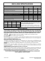
BLAZE KING
PRODUCTS
8003 Insert & 8004 Freestanding
GAS APPLIANCE
Owner's Installation and Operations Manual
SAVE THESE INSTRUCTIONS
FOR YOUR SAFETY
1.
2.
3.
4.
IF YOU SMELL GAS
DO NOT TRY TO LIGHT ANY APPLIANCE
Open Windows
Do not touch any electrical switch or use any
phone in your building.
Extinguish any open flame.
Immediately call your gas supplier from a
neighbors phone. If you cannot reach your
gas supplier, call the Fire Department.
WARNING: IMPROPER INSTALLATION, ADJUSTMENT, ALTERATION, SERVICE OR MAINTENANCE
CAN CAUSE INJURY OR PROPERTY DAMAGE, REFER TO THIS MANUAL FOR ASSISTANCE OR
ADDITIONAL INFORMATION. CONSULT A QUALIFIED INSTALLER, SERVICE AGENCY OR GAS
SUPPLIER. DO NOT BURN WOOD, PAPER OR OTHER MATERIAL IN THIS APPLIANCE.
DO NOT STORE OR USE GASOLINE OR OTHER FLAMMABLE VAPORS AND LIQUIDS
IN THE VICINITY OF THIS OR ANY OTHER APPLIANCE.
MANUFACTURED IN USA BY:
MANUFACTURED IN CANADA BY:
Blaze King Industries
146 A Street
Walla Walla, WA.
99362
Valley Comfort Systems Inc.
1290 Commercial Way
Penticton, BC
V2A 3H5
Ph# 1-509-522-2730
Ph# 1-250-493-7444
OM-8003 & 8004
PAGE 1
Date Printed: Tuesday, February 08, 2005
Revision Date: 06-12-03
Dear Customer:
Thank you for purchasing this Blaze King gas appliance. It is our goal to have every
purchaser of a Blaze King product a satisfied customer. This owner's manual explains the steps
required to safely assemble, install, operate, and maintain your new appliance.
Be a responsible appliance owner. Carefully read these requirements for safe installation
and proper operation BEFORE installing and using your appliance. Obtain permits from the
Building Inspector or Fire Department if local laws require. Check local building and Fire Codes
before installing your appliance. When you have completed the installation, have it checked by
your local inspector. Disregarding inspection and code requirements may jeopardize your
homeowner's insurance. Contact your insurance agent since some insurance carriers require
notification of an appliance installation. We want your Blaze King to give you a lifetime of
trouble-free operation.
We have made every effort to make these installation and operating instructions as
complete as possible. If you have any questions that have not been answered here, contact
your BLAZE KING dealer, Local Building Inspector, Fire Department, or our customer service
department at Blaze King Industries (509) 522-2730 (U.S) or Valley Comfort Systems Inc. (250)
493-7444 (Canada).
Thank you.
The management and employees of BLAZE KING
Mail your warranty card TODAY, and SAVE
your BILL OF SALE. This card is included
with the accessory package inside each
firebox.
In order to receive full warranty coverage and
to expedite service, BKI recommends that you
save your bill of sale and attach it to this page.
Your Blaze King Stove has its own personal
serial number, no two stoves are alike. The
serial number is located on the stove label
attached to a plate in the slot below the
viewing door..
By doing this you will have all the necessary
information in the event that your stove may
need service.
OM-8003 & 8004
PAGE 2
Date Printed: Tuesday, February 08, 2005
Revision Date: 06-12-03
TABLE OF CONTENTS
SPECIFICATIONS MODELS 8003 & 8004 .........................................................................................4
SAFETY NOTICE ...............................................................................................................................4
WARRANTY ................................................................................................................................. 5—6
WHITE MINERAL DEPOSITS .............................................................................................................6
COPY OF LABEL................................................................................................................................7
CAUTIONS .........................................................................................................................................8
ELECTRICAL GROUNDING INSTRUCTIONS ....................................................................................9
PLANNING YOUR STOVE PLACEMENT ...........................................................................................9
OAK LOG INSTALLATION & POSITIONING .....................................................................................10
8003 INSERT KIT CONTENTS .........................................................................................................11
8003 INSERT KIT ASSEMBLY INSTRUCTIONS....................................................................... 11—13
GAS CONNECTIONS .......................................................................................................................14
CLEARANCE DIAGRAM...................................................................................................................14
FLUE VENTING ................................................................................................................................15
BURNER CONVERSION INSTRUCTIONS ............................................................................... 16—18
ORIFICE SIZING TABLE ..................................................................................................................18
LIGHTING PREPARATION ...............................................................................................................19
LIGHTING INSTRUCTIONS...................................................................................................... 19—20
VALVE & WIRE DIAGRAMS .............................................................................................................21
GAS FLAME ADJUSTMENT .............................................................................................................22
REPLACEMENT PARTS LIST ..........................................................................................................23
OM-8003 & 8004
PAGE 3
Date Printed: Tuesday, February 08, 2005
Revision Date: 06-12-03
8003 & 8004 SPECIFICATIONS
NATURAL GAS
8003
L P GAS
8004
8003
8004
Input Rating (BTU/hr) 0-610m (0-2000 ft.) Alt.
38,000
38,000
38,000
38,000
Orifice Size (DMS) 0-610m (0-2000 ft.) Alt.
31
31
50
50
Input Rating (BTU/hr) 610-1370m (2000-4500 ft.) Alt.
35,100
(Cdn. only)
35,100
(Cdn. only)
35,800
(Cdn. only)
35,800
(Cdn. only)
Orifice Size (DMS) 610-1370m (2000-4500 ft.) Alt.
32
32
51
51
Minimum Input (BTU/hr)
20,500
20,500
19,000
19,000
Manifold Pressure (in w.c. / kPa)
3.5 / 0.87
3.5 / 0.87
11.0 / 2.74
11.0 / 2.74
Manifold Pressure - Low Setting (in w.c. / kPa)
1.3 / 0.32
1.3 / 0.32
2.7 / 0.67
2.7 / 0.67
Minimum Inlet Pressure (in w.c. / kPa)
4.5 / 1.12
4.5 / 1.12
12.2 / 3.04
12.2 / 3.04
Unit Comes Factory Equipped For 0-610m (0-2000 ft.) Alt.
Please confirm any information you require for installation or service with the approval label on the appliance.
Freestanding
Firebox
Shroud
Width
26”
27.5”
43”
Height
33-1/4”
23”
29.5”
Depth
19”
22.5”
2”
Weight
180
116
40
The Blaze King Vented Gas Fireplace Heater has been tested, certified,
and listed byITS/ WARNOCK HERSEY INC., Middleton, WI, 53562 for USA
to ANSI Standard Z21.88-1998*CSA 2.33-M98
Gas appliances must be tested and certified by a nationally recognized
testing and certification agency to ANSI Gas Appliance Safety Standard.
SAFETY NOTICE
IF THIS APPLIANCE IS NOT PROPERLY INSTALLED, A HOUSE FIRE, OR EXPLOSION MAY RESULT. FOR YOUR SAFETY,
FOLLOW THE INSTALLATION DIRECTIONS. CONTACT LOCAL BUILDING OR FIRE OFFICIALS ABOUT RESTRICTIONS AND
INSTALLATION REQUIREMENTS IN YOUR AREA. PLEASE READ THIS ENTIRE MANUAL BEFORE YOU INSTALL AND USE YOUR
NEW APPLIANCE. FAILURE TO FOLLOW INSTRUCTIONS MAY RESULT IN PROPERTY DAMAGE, BODILY INJURY or DEATH.
CAUTIONS: NEVER vent the appliance to other rooms or buildings. The appliance must be vented only to the outside.
NEVER burn the appliance with the viewing door open.
FIRE EXTINGUISHER:
Every home should have at least one fire extinguisher. An approved Class A-B-C extinguisher should be mounted on the wall near an exit
and close to the appliance, but not so close that accessibility to the extinguisher could be blocked by a fire. Your local Fire Department can
advise you concerning the most appropriate location.
BUILDING AND FIRE CODES, PERMITS AND INSPECTIONS:
The installation of this gas appliance must comply with your local building and fire codes. Always contact your local Building Inspector and/
or Fire Department before begining the installation process. If required, obtain a permit before installation and have the completed
installation inspected. Remember that not complying with building and/or fire codes may jeopardize your homeowner’s insurance.
CHILDREN:
Do NOT allow children to play near the appliance or with the controls. Severe burns may be inflicted by touching the door or glass, the
front, sides or top of the appliance. Train children to stay away from the appliance, and never leave children unattended in the room when
the appliance is in operation.
SMOKE DETECTORS and CARBON MONOXIDE DETECTORS (CO - DETECTORS):
Install at least one smoke detector on each floor of your home to ensure your safety. It should be located away from the gas appliance and
close to the sleeping areas. Follow the smoke detector manufacturers placement installation and maintenance instructions. Your local Fire
Department may provide assistance in selecting smoke detectors and CO-detectors. It is strongly recommended, for your family’s
protection, that a CO-detector be placed in all homes that utilize gas in any form.
THE APPLIANCE AREA MUST BE KEPT CLEAR FROM COMBUSTIBLE MATERIALS, GASOLINE AND
OTHER FLAMMABLE VAPORS OR LIQUIDS.
OM-8003 & 8004
PAGE 4
Date Printed: Tuesday, February 08, 2005
Revision Date: 06-12-03
BLAZE KING LIMITED LIFETIME WARRANTY
Gas stoves manufactured by Blaze King Industries and/or Valley Comfort Systems Inc. are covered by a limited
lifetime warranty against manufacturers defects in material and workmanship. Details of this comprehensive
warranty program are outlined below. In addition to the terms outlined for the limited lifetime warranty, our products
carry a 5 year warranty which covers mechanical and electrical components including labor costs outlined below.
The combination of these warranty policies provide a very strong coverage package that we are proud to offer you,
our customers. Our Blaze King tradition of building high quality products for over 25 years is really your most
important assurance of quality but it's nice to know that should something fail (and it occasionally does) you are
covered by a warranty policy that leads the industry. To ensure the coverage is in place you must have your unit
properly installed by an authorized Blaze King dealer and you must register your ownership. Blaze King's
warranty policy applies only to units sold, installed and/or for use in the USA or Canada. No person is
authorized to modify this warranty or make any additional warranties on behalf of the manufacturer, Blaze
King.
Components and parts 5 year warranty:
Blaze King warrants the following parts; blower motors, door gasket, blower speed control, logs, pilot assembly,
gas valve, gas lines, thermocouple and/or thermopile against defects in material or workmanship to the original
purchaser, for five years following the date of purchase.
Labor costs during the 5 year warranty period:
Blaze King manufacturers warranty covers labor costs to the original purchaser based on our schedule of approved
charges, provided to our authorized dealers. Blaze King will only be responsible for labor costs provided by our
authorized dealers and based upon the schedule.
Limited Lifetime Coverage
This warranty contains different terms that cover specific parts of the gas appliance. Blaze King warrants the
following parts of the gas appliance against defects in material or workmanship to the original retail purchaser. For
the first five years of ownership, the combustion chamber, heat exchanger and burners will be replaced by Blaze
King, conditional upon production availability. From year 6 through to the end of ownership by the original
purchaser, Blaze King will provide replacement or repair of the aforementioned parts, conditional upon current
production availability, at 50% of current retail price but does not cover any charges relating to labor. This portion
of the warranty coverage is not transferable and applies only to the original purchaser.
How to Get Service
If this product requires repair or replacement due to defects in material or craftsmanship during the first five years of
ownership, contact your Blaze King dealer and explain the nature of the problem. If the dealer is unable to repair or
replace the product to your satisfaction then contact Blaze King at 509-522-2730 in the USA or 250-493-7444 in
Canada. If a replacement part is sent directly to you, please contact Blaze King to obtain a Return Authorization
Number (RA#) for all defective parts. Blaze King will refuse delivery of any returned packages not clearly showing
an (RA#). All expenses relating to the shipping of defective parts or entire stoves will be at purchaser's expense.
Blaze Kings Responsibilities:
If the purchaser has complied with all the terms and conditions of this warranty and if the purchaser has notified
Blaze King of the defect prior to the expiration of any warranted items, the following procedure will occur. Blaze
King will inspect the product to determine that there is indeed a defect and that the defect is covered by warranty.
Blaze King will either repair or replace the product at its' discretion. Under no condition whatsoever does Blaze
King provide or imply warranty coverage for venting components used in the installation of our products. This
warranty details the obligations and liabilities of Blaze King and no other warranties are expressed or implied.
Blaze King reserves the right to investigate and settle all claims against warranted parts at their discretion. In no
event shall Blaze King be held responsible for indirect or consequential damages of any nature which are in excess
of the original purchase price of the product. Blaze King may at its' discretion discharge any or all obligations by
refunding the wholesale price of any defective part or parts.
Misuse of Stove Nullifies Warranty:
The above warranty is conditional upon the proper installation and use of the product according to the
manufacturers instructions as specified in the "Owners Installation & Operations Instructions" and in
compliance with applicable local building and fire codes. Blaze King recommends the local building inspector or fire
department inspect the unit prior to initial use. Consult the "Owners Installation & Operations Instructions" supplied
with each unit prior to installation or operation. Alteration, abuse, lack of maintenance, faulty repairs or misuse will
void the warranty. Abuse includes but is not limited to the use of fuels other than as specified in the "Owners
Installation & Operations Instructions."
Legal Rights of Purchaser:
This warranty gives you specific legal rights, you may have other rights that vary from state to state (or province to
province).
OM-8003 & 8004
PAGE 5
Date Printed: Tuesday, February 08, 2005
Revision Date: 06-12-03
BLAZE KING LIMITED LIFETIME WARRANTY
Blaze King Assurance:
Included with each gas stove manufactured by Blaze King is a Warranty Card, which must be completed in its
entirety and returned to Blaze King within ten days from the date of purchase. Blaze King will be unable to
properly administer the warranty if the card is not completed and registered on file.
This Warranty will pay to repair and or replace parts which fail under normal usage at labor rates established by
this Agreement. Extra charges such as mileage, overtime or shipping are not covered. Nuisance calls are not
covered by this Warranty. This Warranty is for residential stoves and does not apply to commercial applications.
Only failure attributed to normal usage of the electronic and mechanical functions of the stove are covered.
Failure due but not limited to, abuse, negligence, impact, fire, lightning, power failures and or surges, rust and
corrosion are not covered. Damage and or repairs to cabinets and all exterior components, remote controls, and
normal maintenance, related duct work, power surges, electrical spikes or electrical circuit overloads, filters,
knobs, glass, gaskets, block and tile etc., are not covered. Additional or unusual utility bills incurred due to any
malfunction or defect in equipment listed on this Warranty are not covered. Labor cost of gaining access to or
removal of a unit that requires special equipment or tools such as cranes, ladder trucks, etc., are not covered.
This Warranty does not include, cleaning, adjustments of the customer controls, customer product education or
any other regular service/maintenance functions. Labor, materials, expenses or equipment required to comply
with the law and or regulations set forth by any governmental agencies are not covered by this Plan.
WHITE MINERAL DEPOSITS
One of the byproducts of the combustion process in a gas appliance is a mineral which can show up as a white
film on the ceramic glass in the viewing door. The composition of the deposit varies widely from location to
location and also from time to time in the same locations. You may have the problem for a time and then not see
it for many months when it will reappear in your area. It seems this is associated with the varying sulfur content of
the gas. We have discussed this problem with ceramic glass manufacturers and they cannot give us a definitive
answer to this problem. We have input from several dealers who have tried various cleaning products with varying
results. We can only make the following recommendations and cannot assure you of the results in our particular
case.
WARNING!!
Never clean the ceramic glass or any other part of the appliance while it is still hot. Please shut
off your appliance and wait for it to cool down prior to cleaning.
1) Clean the glass regularly as soon as you notice the buildup (white film), if the film is left for a long period of
time to build up and bake on, it is much harder to remove and may become impossible to remove.
2) NEVER use an abrasive cleaner on the ceramic, any abrasion of the surface has an immediate effect to
lessen the strength of the glass. An emulsion type cleaner is best.
3) Use a soft damp cloth to apply the cleaner and dry the glass with a soft dry cloth, preferably cotton only. Most
paper towels and synthetic materials are abrasive to ceramic glass and should be avoided.
WHITE OFF by Rutland has been tested and qualified as being effective to remove most ugly mineral
deposits from ceramic glass.
NOTE: This is a problem beyond BLAZE KINGS control and is not covered under warranty.
DOOR SEAL GASKET
The front door of your new Blaze King B vent is gasketed and has been adjusted for a tight seal. With usage the
door gasket material may compress. The door may require periodic adjustment to maintain a proper seal. The
time to make this adjustment will vary depending upon individual hours of use, btu settings, and frequency of
opening and closing the door. Check the door on your appliance periodically, especially during the first 90 days of
operation, to ensure it is sealing properly. Your Blaze King dealer/installer should be contacted to properly adjust
the door if required.
OM-8003 & 8004
PAGE 6
Date Printed: Tuesday, February 08, 2005
Revision Date: 06-12-03
COPY OF APPROVAL LABEL
BLAZE KING PEGASUS 8003 & 8004
Vented Gas Fireplace Heater
Not For Use With Solid Fuel
Not for installation in a Mobile Home
Certified for U.S. and Canada
Homologue Pour Le Canada
Project# 3041190
WH-
This stove is factory equipped for:
Natural Gas
Propane
Tested to ANSI Z21.88-1998*CSA 2.33-M98 “Vented Gas Fireplace Heaters” and CAN/CGA
2.17-M89 “ High Altitude” This vented gas fireplace is not for use with air filters.
Insert model 8003
Freestanding model 8004
NATURAL GAS
L P GAS
Freestanding / Insert
Freestanding / Insert
Input Rating (BTU/hr) 0-610m (0-2000 ft.) Alt.
38,000
38,000
Orifice Size (DMS) 0-610m (0-2000 ft.) Alt.
31
50
Input Rating (BTU/hr) 610-1370m (2000-4500 ft.) Alt.
35,100 (Can. Only)
35,800 (Can. Only)
Orifice Size (DMS) 610-1370m (2000-4500 ft.) Alt.
32
51
Minimum Input (BTU/hr)
20,500
19,000
Maximum Output with Fan On (BUT/hr)
29,800
29,600
Unit Comes Factory Equipped For 0-610m (0-2000 ft.) Alt.
This appliance
be install in accordance 3.5
with
the manufacture’s
instructions.
Manifold
Pressure (inmust
w.c. / kPa)
/ 0.87
11.0 / 2.74
This appliance must be installed in accordance with local codes if any; if not follow the current ANSI Z223.1 or
Manifold
Pressure - Low Setting (in w.c. / kPa)
1.3 / 0.32
2.7 / 0.67
CAN/CGA-B149
MINIMUM
FROM COMBUSTIBLE
CONSTRUCTION
Minimum Inlet Pressure
(in w.c. / CLEARANCES
kPa)
4.5 / 1.12
12.2 / 3.04
Unit to Sidewall
11 in. (280mm)
Alcove Minimum Width
Unit to Backwall
6 in. (152mm)
Alcove Minimum Height
Unit to Adjacent Wall Corner
4 in. (102mm)
Alcove Maximum Depth
Unit Top to Mantel
18 in. (457mm)
18” Floor Protection required if unit is not on a 6” or higher elevated Hearth (8003 only)
47” (1194mm)
54” (1372mm)
30” (762mm)
Electrical Rating: 115 Volts, 0.7 Amperes, 60HZ.
DANGER: Risk of electrical shock. Disconnect power before servicing unit. Do Not route power cord beneath
heater.
Not for use with Solid Fuel.
Manufactured by:
Blaze King Industries
146A St.
Walla Walla, WA.
99362 USA
Manufacture Date:
Valley Comfort Systems
1290 Commercial Way
Penticton, B.C
V2A 3H5 Canada
JAN
MAY
SEP
2003
FEB
JUN
OCT
2004
MAR
JUL
NOV
2005
APR
AUG
DEC
2006
0754C
OM-8003 & 8004
PAGE 7
Date Printed: Tuesday, February 08, 2005
Revision Date: 06-12-03
CAUTIONS
∗
DO NOT OPERATE APPLIANCE WITH THE GLASS DOOR REMOVED, OPEN, CRACKED, OR BROKEN.
REPLACEMENT OF GLASS SHOULD BE DONE BY A LICENSED OR QUALIFIED SERVICE PERSON AS
AUTHORIZED BY BLAZE KING. IF THE APPLIANCE DOOR NEEDS REPLACING IT MUST BE REPLACED AS
A COMPLETE UNIT SUPPLIED BY BLAZE KING.
∗
∗
DO NOT USE SUBSTITUTE MATERIALS-DO NOT ABUSE GLASS BY STRIKING OR SLAMMING DOOR SHUT. DO NOT USE
ABRASIVE CLEANERS OR CLEAN WHILE HOT
This appliance installation must conform with local codes and with current editions of the National Fuel Gas code ANSI Z223.1 or CAN/CGA
1-B149.
The appliance and its individual shut off valve must be disconnected from the gas supply piping system during any pressure testing of that
system at test pressures in excess of 1/2 psi (3.5 kPa)
The appliance must be isolated from the gas supply piping system by closing its individual manual shut off valve during any pressure testing
of the gas supply piping system at test pressures equal to or less than 1/2 psi (3.5 kPa). The appliance installer must provide a 1/2 inch
N.P.T. plugged tapping accessibility for test gage connection immediately upstream of the gas supply connection to the appliance.
Should overheating occur or the gas supply fail to shut off, shut off the manual gas valve to the appliance before shutting off the electrical
supply.
8003: If the hearth rises less than 6 inches above floor then R 1.1 or better is required at least 18 inches in front of, and spanning the width
of the unit. This appliance is equipped with a safety control system designed to protect against improper venting of combustion products.
The 8003 must be installed in an existing masonry fireplace or Listed Wood Burning “0” Clearance Fireplace.
∗
∗
∗
∗
∗
8004: This appliance may be installed directly on carpeting, tile or other combustible materials.
This gas appliance must not be connected to a chimney flue serving a separate solid fuel burning appliance.
Periodic examination of the venting systems is required.
If the appliance is installed in the basement, please see local codes before using propane.
USE ONLY THE GLASS DOOR CERTIFIED WITH THIS APPLIANCE
∗
∗
∗
∗
∗
∗
WARNING
IMPROPER ASSEMBLY AND/OR INSTALLATION OF YOUR BLAZE KING GAS APPLIANCE OR FAILURE TO OPERATE IT
ACCORDING TO THE GUIDELINES DETAILED IN THESE INSTRUCTIONS WILL VOID THE APPLIANCE WARRANTY, CAN
CAUSE A HOUSE FIRE, AND MAY ENDANGER YOUR FAMILY. FOR YOUR SAFETY, FOLLOW THE ASSEMBLY AND
INSTALLATION INSTRUCTIONS CAREFULLY. CONTACT LOCAL BUILDING OR FIRE OFFICIALS ABOUT RESTRICTIONS
AND INSTALLATION INSPECTIONS IN YOUR AREA. PLEASE READ THIS ENTIRE MANUAL BEFORE YOU INSTALL AND
USE YOUR NEW APPLIANCE.
∗
Due to high temperatures, the appliance should be located out of traffic and away from furniture and draperies.
∗
Children and adults should be alerted to the hazards of high surface temperatures and should stay away to avoid burns or clothing ignition.
∗
Young children should be carefully supervised when they are in the same room as the appliance.
∗
Clothing or other flammable material should not be placed on or near the appliance.
∗
Any safety screen or guard removed for servicing a room heater must be replaced prior to operating the appliance.
∗
Installation and repair should be done by a qualified service person.
∗
The appliance and venting should be inspected before use and at least annually by a qualified service person.
∗
More frequent cleaning may be required due to excessive lint from carpeting, bedding materials, etc.
∗
It is imperative that control compartments, burners, and circulating air passageways of the appliance are kept clean.
∗
To clean the stove, make sure the appliance is off and cold. Then remove the logs and embers and use a vacuum to clean burner and air
openings in the bottom of the appliance and also on the back of the appliance. Replace the logs and embers.
The draft hood must be in the same atmospheric pressure zone as the combustion air inlet. The flow of combustion and ventilation air must
not be obstructed.
Do not use this heater if any part has been under water. Immediately call a qualified service technician to inspect the heater and
to replace any part of the control system and any gas control which has been under water.
∗
∗
WARNING: FAILURE TO USE ONLY PARTS SPECIFICALLY APPROVED WITH THIS APPLIANCE MAY RESULT
IN PROPERTY DAMAGE OR PERSONAL INJURY.
OM-8003 & 8004
PAGE 8
Date Printed: Tuesday, February 08, 2005
Revision Date: 06-12-03
ELECTRICAL GROUNDING INSTRUCTIONS
WARNING: The appliance, when installed, must be electrically grounded in accordance with local codes or in the absence of local codes
with the current National Electrical Code ANSI/NFPA 70, or the current Canadian Electrical Code CSA.C22.1.
This appliance is equipped with a three prong (grounding) plug for your protection against shock hazard and should be plugged directly into
a properly grounded three prong receptacle.
DO NOT cut or remove the ground prong from this plug.
PLANNING YOUR STOVE PLACEMENT
As you plan your installation, consider the following:
The stove should be placed in the home in a position that is as central as possible. Consider safety, convenience, traffic flow, and the fact
that the stove will need a venting system. Pay special attention to prevailing winds when choosing termination location.
DUE TO HIGH TEMPERATURES, THE ROOM HEATER SHOULD BE LOCATED OUT OF TRAFFIC AREAS AND AWAY FROM
FURNITURE OR DRAPERIES. MINIMUM CLEARANCES SHOWN ON PAGE 14 ARE TO PREVENT WALLS AND CEILINGS FROM
CATCHING ON FIRE.
For the type of vent system to be used, see page 15. Electrical Power is 115-60 HZ. The stove is equipped with a fan assembly with a six
foot electrical cord. Do not route the cord in front of the stove. Position the stove in its final location. A floor protector may be used for
aesthetics, however, the freestanding 8004 units may be installed directly onto carpet, vinyl, or any other flooring.
WARNING
ONLY PERSONS LICENSED TO WORK WITH GAS PIPING MAY MAKE THE NECESSARY GAS CONNECTION TO THIS
APPLIANCE. YOU ARE NOW READY TO HOOK UP THE GAS SUPPLY. BE SURE GAS PLUMBING INSTRUCTIONS AND ALL
PROVINCIAL AND LOCAL CODES ARE CAREFULLY FOLLOWED. USE APPROVED FLEXIBLE GAS CONNECTIONS OR RIGID
PIPING DEPENDING ON PROVINCIAL AND LOCAL CODES TO ATTACH BURNER TO GAS SUPPLY. BE SURE TO USE PROPER
SIZE GAS SUPPLY LINE. CAREFULLY CHECK ALL CONNECTIONS FOR GAS LEAKS WITH SOAP AND WATER SOLUTION.
EACH INSTALLATION MUST CONFORM TO ALL LOCAL, PROVINCIAL AND NATIONAL CODES. REFER TO THE NATIONAL FUEL
GAS CODE AND LOCAL ZONING AND CODE AUTHORITIES FOR DETAILS ON INSTALLATION REQUIREMENTS. BLAZE KING
APPLIANCES MUST BE VENTED TO THE OUTSIDE IN ACCORDANCE WITH THE LATEST EDITION OF THE NATIONAL FUEL GAS
CODE. IN THE ABSENCE OF LOCAL CODES, THE INSTALLATION MUST CONFORM WITH CURRENT EDITION OF THE
NATIONAL FUEL GAS CODE ANSI Z223.1, ALSO KNOWN AS NFPA 54, OR CAN 1-B149.
OM-8003 & 8004
PAGE 9
Date Printed: Tuesday, February 08, 2005
Revision Date: 06-12-03
OAK LOG & BRICK PANEL INSTALLATION
A.
BACK LOG: This larger log should be placed in the back of the stove close to the far back wall. The flat
side of (Log A) should rest flush against the flat part of the back bracket with the rough textured side of the log
pointing towards you. The curved part (of Log A) should be facing upwards.
B.
FRONT LOG: This smaller log fits in the right and left side brackets closest to you. The flat portion (of Log
B) should be placed flush against the back of the bracket. After setting this log in the brackets, the rough textured
side of the log should be pointing outward, facing you.
C.
LEFT TWIG: This Y shaped log (C) sits on the left side of the front and back logs (A and B). This log (C)
should be placed on the grooves so that the base of the Y is sitting on the groove in the front log and the right leg
of the Y rests on the peg on the back log.
D. RIGHT TWIG: On the right side of Log B. there is a groove. Invert the twig so that the legs are pointing
down. Place the left leg of the twig into the groove of Log B and place top portion of twig onto pin. (Note: hole
should already be present in upper portion of twig)
Please note that brick panels are optional.
Slide the rear brick panel
in then insert both side
panels. Turn brick panel
retainer clips (at top of
each side panel) down to
hold brick panels in
place.
WARNING: DANGEROUS
OPERATING CONDITIONS MAY
OCCUR IF THESE LOGS ARE NOT
POSITIONED IN THEIR PROPER
LOCATIONS. READ THE LOG
PLACEMENT INSTRUCTIONS
ABOVE CAREFULLY AND REFER
TO THE DIAGRAMS TO THE RIGHT.
Log A
EMBER PLACEMENT: Place embers
directly over the first set of small holes in
the front of the burner tray. Embers
should be evenly spread across this first
row of small holes.
Logs A & B
Large Log
Logs A,B & C
Small Log
Log Holder
Log Holder
Embers
Logs A, B, C & D
Burner Tube
OM-8003 & 8004
PAGE 10
Date Printed: Tuesday, February 08, 2005
Revision Date: 06-12-03
8003 INSERT KIT CONTENTS
LOWER LEFT AND RIGHT SHROUDS
FIG. 26
TOP TRIM
MAIN SHROUD - FIG. 27
OUTER TOP - FIG. 28
WIRE SUPPORT BRACKET
FIG. 29
VALVE BRACKET
FASTENERS - FIG. 30
Left & Right Upper Shroud Bracket
L
LEFT & RIGHT SIDE
COVER PLATES
R
TRIM PACK - FIG. 31
Tie Wrap X6
X5
Long Trim
#2 Square Drive Screw
X 10
Short Trim
Strain Relief
8003 INSERT ASSEMBLY INSTRUCTIONS
SCREW AND HOLE
IDENTIFICATION FIG. 32
ATTACH LOWER LEFT AND RIGHT
SHROUDS FIG. 33
ATTACH LEFT & RIGHT
COVER PLATES
4 Screws
Wire Support Bracket
ATTACH OUTER TOP TO
MAIN SHROUD FIG. 35
POSITION MAIN SHROUD
FIG. 36
INSTALL WIRE SUPPORT BRACKETS
AND ROUTE WIRES FIG. 34
Snap Disc
INSTALL MAIN SHROUD
ASSEMBLY FIG. 37
Wire Support Brackets
OM-8003 & 8004
PAGE 11
Date Printed: Tuesday, February 08, 2005
Revision Date: 06-12-03
8003 INSERT ASSEMBLY INSTRUCTIONS
DESCRIPTION
MAIN SHROUD
LEFT LOWER SHROUD
RIGHT LOWER SHROUD
LEFT UPPER SHROUD BRACKET
RIGHT UPPER SHROUD BRACKET
VALVE BRACKET
WIRE SUPPORT BRACKET
TIE WRAP
LEVELING BOLTS 3/8”
LOCK NUTS
#2 X 1/2” SQ. DR. SCREWS
WIRE CLAMP
STRAIN RELIEF
LEFT COVER PLATE
RIGHT COVER PLATE
CONTENTS
PART NUMBER
R8184-L
R818R
R8186-L
R8186-R
R8144B
R8115A
0030
0410
0150
0296A
0877
0371
R8187-L
R8187-R
QUANTITY
1
1
1
1
1
1
2
6
2
2
20
1
1
1
1
Insert Units can only be installed in a masonary fireplace or
a listed wood burning “0” clearance fireplace.
1. Remove fire box from carton. Place on floor.
2. Note 4 screws on each side of the fire box.(Fig. 32, p.11) Remove screws.
3. Attach the left and right cover plates to the firebox using the front top and bottom screws on each side of the firebox as indicated in the
illustration on the previous page. Note that you will have to remove the door latch on the right side of the stove, secure the right cover plate,
and then re-install the door latch.
4. Attach both lower left and right shroud assemblies by lining up the bottom two screw holes on each side of the fire box, with the
corresponding holes in the shroud assemblies, and securing with the screws previously removed. ( Fig. 33, p. 11)
5. Attach left and right upper shroud brackets where the top two screw holes on each side are. When the bracket is attached there should
be a single screw hole facing forward towards the front of the stove. Brackets have a 3/4” bend on 2 sides, these point down.
6. Locate two oblong screw holes on top of the right lower shroud. This is where the insert valve bracket will mount under.
7. Position the valve bracket just behind the right lower shroud. The small support leg on the bracket should be facing up and towards the fire
box. Line up the two holes in the triangular bottom of the valve bracket, underneath the two oblong holes of the shroud. Secure with two
screws.
WARNING: FAILURE TO USE ONLY PARTS SPECIFICALLY APPROVED WITH THIS APPLIANCE MAY RESULT IN
PROPERTY DAMAGE OR PERSONAL INJURY.
8. The small support leg should now be lined up with the hole in a tab coming off of the fire box. Secure support leg to fire box with screw
provided in kit.
9. Locate two screws securing the Robertshaw valve to the fire box. Remove screws.
10. Pull valve over to new valve bracket, line up the corresponding holes and secure with two screws. The valve MUST be moved from its
shipping bracket to the insert bracket.
11. Locate two holes on the top right edge of the right hand shroud. This is where the burner switch/piezzo push button assembly will mount.
12. Locate the burner switch/piezzo button assembly secured adjacent to the valve. Cut the tie wrap and move the assembly over to the right
shroud and line up the two holes on the switch bracket with the holes on the top lip of the right shroud. Secure with two screws.
13. At this point in time it is necessary to determine which side of the shroud the fan cord will come out of. Two wire support brackets are
included in the insert kit. These attach to the left and right side of the fan box with two screws. If the cord is to be routed out of the left side, it
is necessary to install only one support bracket. If fan cord is to be routed out the right side then both support brackets must be installed. (Fig.
32,34, p. 11)
14. Install bracket(s) and secure with two screws.
15. Locate on the back of the fan box, two screw holes. One on the lower left, one on the lower right. Secure cord with the plastic cable
clamp provided on the appropriate side.
16. Connect the fan and snap disc wires to the rheostat located on the left side of stove. Install rheostat knob.
17. Secure the wires to the wire support bracket using a tie wrap routed through each hole in the bracket.
NOTE: IF FAN CORD IS ROUTED ON THE LEFT SIDE, SECURE FAN CORD ALONG WITH RHEOSTAT AND SNAP DISC WIRES. IF
ROUTED OUT THE RIGHT SIDE, SECURE TO WIRE SUPPORT BRACKET ON THE RIGHT SIDE.
OM-8003 & 8004
PAGE 12
Date Printed: Tuesday, February 08, 2005
Revision Date: 06-12-03
8003 INSERT ASSEMBLY INSTRUCTIONS
18. You may position the unit in your existing masonry or listed zero clearance fireplace at this time. If your hearth is lower than the
bottom of the fire place you must install the leveling bolts provided in the insert kit. Spin a lock nut onto each bolt, locate a threaded hole
underneath the front bottom portion of the fire box, one on the left, one on the right. Insert each bolt and adjust as needed. Be sure to
tighten the lock nut against the bottom of the fire box.
NOTE: If the bolts included in the kit are not long enough, simply obtain the appropriate length at your local hardware store or purchase a
Hearth Extension Kit from your Dealer
WARNING! INSERT IS FRONT HEAVY- USE CAUTION WHEN INSTALLING . TWO PEOPLE ARE
RECOMMENDED TO PERFORM THIS TASK
19. Connect the 1/2” flex gas supply line to the valve.
NOTE: The 8003 fire box comes with a wall thermostat. The leads should be hooked up to the terminals marked “TH” and “THTP”. (See
P. 21) Use 18 gauge or better wire.
20. Connect either single wall or flex pipe to the flue collar.
NOTE: If necessary to facilitate installation, the draft hood can be removed from the fire box, connected to the vent pipe, then re-installed
onto the stove.
21. Secure outer top to the main shroud with five screws. Position the back of top against the main shroud and line up the corresponding
holes. The screws will pass through the back of the shroud then into the top. (Fig. 35, p. 11)
22. Locate the two brackets that hold the decor above the viewing door. Note that there is a empty slot on each bracket, this is where the
bottom lip on the front of the outer top will engage.
23. Position the main shroud in front of the stove at a 45 deg. angle (top towards you). Engage the bottom “legs” of the shroud around the
outside of the lower left and right shrouds. (Fig. 36, p. 11)
24. Tilt the main shroud upward and engage the bottom inside lip of the outer top into the empty slots on the decor brackets. Square up
the main shroud to the fire box. (Fig. 37, p. 11)
25. Open the left shroud door. Note the holes now lined up to the right of the magnetic catch. Secure the main shroud to the upper
shroud bracket with one screw. Repeat with the right side.
26. Locate two access holes above the fan cord exits on both left and right sides of the main shroud. Pass a screw through the access
hole, through the second hole in the main shroud, and tighten to the lower shroud. Repeat with second screw.
27. Repeat with opposite side.
STRAIN RELIEF INSTALLATION
28. Take the fan cord and push it up into the exit hole on the side of the shroud. Wrap
the strain relief around the cord, compress the top and bottom with a pair of pliers,(see
illustration right) and push into the hole. Push insert flush against fire place.
INSERT TOP TRIM INTO THE RECESSED HOLE OF THE OUTER TOP
AT THIS TIME
AIR SHUTTER ROD INSTALLATION
Note: On all units manufactured from May 2003 and on the air shutter is installed at the factory.
To adjust open the viewing door and grasp small rod located in the back right of the firebox and with pliers lift up and/or pull down to adjust
the flame pattern as desired.
Note: If burner tray is removed:
MAKE SURE THAT THE SPRING IS IN PLACE ON THE MAIN BURNER ORIFICE, AND THAT THE MAIN BURNER
ORIFICE SEATS ITSELF INSIDE THE BURNER AIR SHUTTER.
OM-8003 & 8004
PAGE 13
Date Printed: Tuesday, February 08, 2005
Revision Date: 06-12-03
GAS CONNECTION
The gas line may be installed at this time. Make sure to follow all provincial and local codes. It is recommended
by Blaze King that gas connections be made by a licensed and qualified installer. The appliance can be
connected to the supply line with either rigid or approved flexible gas connection. Check with provincial and local
codes.
Attach a 1/2 inch close nipple to the control valve. At this point there must be a 1/2 inch N.P.T. plugged tee
accessible for a test gauge. The connection pipe connected to a 1/2 inch shut off valve, should be mounted to the
supply line.
PIPING DETAIL:
NOTE:
DO NOT DAMAGE OR KINK THE FLEX CONNECTOR. CHECK FOR GAS LEAKS WITH SOAP AND
WATER SOLUTION.
1/2 INCH FLEX OR RIGID PIPING MAY BE USED TO CONNECT THE GAS SUPPLY TO THE UNIT
DEPENDING ON PROVINCIAL AND LOCAL CODES.
GAS SUPPLY PRESSURE:
NATURAL GAS............................7 inch w.c. recommended 5.5 / 1.37 min / 10.5 / 2.62 max
LP GAS.......................................11 inch w.c. recommended 11.0 / 2.74 min / 13.0 / 3.20 max
1/2” Gas Shut Off Valve Open Position
Supply Line
1/2” Flex Connector Or Rigid Pipe
Robert Shaw and Honeywell valves have built in line and manifold pressure taps built in for easy access.
8003 & 8004 CLEARANCE DIAGRAMS
8004 FREE STANDING
8004 FREE STANDING
20”
25”
6”
Min. To
11”
Min. To
Combustables
5-1/4”
Min. To
30”
Gas Supply
18”
8003 INSERT
8004 FREE STANDING
Shroud Can Not Touch Combustables
If Unit Is Less Than 6” Above Floor Level
R1.1 Protection Is Required At Least 18”
InFront Of Unit. (3/8” Millboard Is Sufficient)
11”
10”
Min. To
Combustables
12”
9 1/2” Str. Up With
45 Deg.
13
OM-8003 & 8004
PAGE 14
C
Date Printed: Tuesday, February 08, 2005
Revision Date: 06-12-03
FLUE VENTING
WARNING: Always refer to current editions of local , provincial, state safety codes.
Please follow vent manufactures specifications for safe and efficient installation.
CAUTION: EACH OF THE VENT MANUFACTURERS HAVE THEIR OWN METHOD OF CONNECTION. DO
NOT MIX B-VENT FROM VARIOUS MANUFACTURERS B-VENT MUST BE USED WHEN PASSING
THROUGH A WALL, CEILING, OR ROOF.
Rain Cap
To Prevent Injury, Persons Not Familiar With The Unit
Should Not Be Allowed to Operate It
Min 3ft
Storm Collar
Be Alert To The Danger Of High Temperature Surfaces.
Advise All Children & Adults That The Glass & Doors, Etc.
Cannot Be Touched During Or Soon After Operation,
Jack Flashing
Alcove minimum width 47”
Max. Alcove
Depth 30”
See Chimney Manufacturer’s
Specifications & Local Building
Codes For Proper Clearances
B Vent
Min. Height
Must Be At
Least Twice
Of Lateral
Distance
Pipe Collar
6” Min.
12” Min.
Recommended
54”
6” Min On
Single Wall
B Vent Or Single Wall
If Single Wall Pipe Is Used, Wall
Thimble Must Be Used
Alcove Installation
Through The Ceiling
Use Gas Vent Cap
Flue Must Be Sealed Around
Pipe At Top Of Chimney
Blaze King Requires The Chimney
To Be Relined.
(4” Aluminum Flex Pipe Is Sufficient)
Shroud Can Not
Touch Combustibles
18” Min.
6” Min.
OM-8003 & 8004
PAGE 15
If distance is less than 6” from stove
apron to floor, floor protection with an
insulation value of at least R1.1 must
extend 18” out from, and expand the
entire width of the shroud.
Date Printed: Tuesday, February 08, 2005
Revision Date: 06-12-03
BURNER CONVERSION
The conversion kit shall be installed by a
qualified service agency in accordance
with the manufacturer's instructions and
all applicable codes and requirements of
the authorities having jurisdiction. If the
information in these instructions is not
followed exactly, a fire, explosion or
production of carbon monoxide may result
causing property damage, personal injury
or loss of life.
The qualified service
agency is responsible for the proper
installation of this kit. The installation is
not proper and complete until the
operation of the converted appliance is
checked as specified in the owner
instructions supplied with the kit.
Cet èquipement de conversion sera
installè par une agence qualifièe de
service conformèment aux instructions du
fabricant et toutes exigences et codes
applicables de l`autorizès avoir la
juridiction. Si l`information dans cette
Instruction n`est pas suivie exactement,
un feu,
explosion ou production de
protoxyde de carbone peut rèsulter le
dommages causer de propiètè, perte ou
blessure personnelle de vie. L`agence
qualifièe de service est esponsable de
l`installation propre de cet èquipement.
L`installation n`est pas propre et complète
jusqu`à l`opèration del`appareil converti
est chèque suivant les critères ètablis
dans les instructions de propriètaire
provisionnèes avec l`èquipement.
HIGH ALTITUDE STATEMENT
This unit has been tested for installations at a high altitude up to 1370 meters (4500 ft.) in
accordance with Canadian test standard CAN/CGA-2.17. Higher altitudes effect atmospheric
pressure and heat value of gaseous fuels. When installing this unit at high altitudes, the rated
input will be lower than at sea level. The lowered oxygen content in the air and lowered gas
density requires installing a different orifice in order to achieve clean combustion of the unit.
Consult the unit data plate for proper high altitude orifice size, and fill out the information sticker
attached to the unit when field converting. For high altitude installations, consult the local gas
distributor or the authority having jurisdiction for proper rating methods.
USE ONLY CONVERSION KITS LISTED BELOW
(Models 8003 & 8004) Robertshaw Kits
BLAZE KING PART#’s:
NATURAL GAS- Z0747A (0-2000ft. # 31 main orifice) &
Z0749 (2,000-4500ft.# 32 main
orifice)
PROPANE GAS- Z0736 (0-2000ft/#50 main orifice) &
Z0736H (2,000-4500ft.#51 main
orifice)
OM-8003 & 8004
USE ONLY CONVERSION KITS LISTED BELOW
(Models 8003 & 8004) Honeywell Valve & Pilot
BLAZE KING PART#’s:
NATURAL GAS- Z0751 (0-2000ft. #31 main orifice) &
Z0751B (2,000-4500ft.# 32 main orifice)
PROPANE GAS- Z0769 (0-2000ft/#50 main orifice) &
Z0769H (2,000-4500ft.#51 main orifice)
PAGE 16
Date Printed: Tuesday, February 08, 2005
Revision Date: 06-12-03
PILOT CONVERSION LP OR NATURAL GAS
Pilot Flame Should
Look Like This
Robertshaw Pilot
Thermopile
Manifold Pressure (In w.c. / kPa)
Collecteur de pression (In w.c. / kPa)
Manifold Pressure Lo setting (In w.c. / kPa)
Collecteur de pression à bas rendement (In w.c. / kPa)
Minimum Inlet Pressure (In w.c. / kPa)`
Max Inlet Pressure (In w.c. / kPa)
Input (but/hr)
NATURAL GAS
3.5 / 0.87
LP GAS
11.0 / 2.74
1.3 / 0.32
2.7 / 0.67
4.5 / 1.12
10.5 / 2.61
35,100
12.2 / 3.04
13.0 / 3.27
35,800
Pilot Flame Should
Look Like This
IN
OUT
IN
TP
TH
TP
ON
OUT
TH
INLET
PRESSURE
TAP
OT
IL
OFF
OU
PILOT ADJ.
Top View Of Burner
P
OUTLET
PRESSURE
TAP
LO
O
PIL
OF
HONEYWELL PILOT HOOD
ROBERTSHAW PILOT
IN
PILOT ADJUSTMENT
SCREW
(REMOVE CAP TO ACCESS
ACTUAL ADJUSTMENT
SCREW)
TH
TP
TH
TP
PILO
HONEYWELL
VENT
HI
ON
ROBERTSHAW
Note manifold pressures listed above. Read lighting instructions. Cycle unit on, back out brass screw a FEW
turns in the appropriate pressure test nipple as indicated below. Test for appropriate range, if regulator is not
properly set, replace. Stick conversion marking on the panel inside the right door, just above the valve. Fill out
conversion information on label inside of the left door on unit.
ADJUST PILOT AS NECESSARY, SEE ILLUSTRATION ABOVE FOR PROPER SIZE AND LOOK OF PILOT LIGHT.
BURNER CONVERSION ROBERSHAW VALVE
LP OR NATURAL GAS
CONVERSION KIT SHOULD INCLUDE REGULATOR, MAIN BURNER ORIFICE, AND PILOT ORIFICE.
CAUTION: Before proceeding with the conversion the gas supply must be shut off prior to disconnecting
the electrical power.
1. ................ Remove the 2 screws holding the regulator plate. Remove regulator and gasket.
Position new gasket over pins and install new regulator with notched corner up.
2 ................. Open the front access door.
3. ................ Remove embers and logs.
4. ................ Lift front of burn tray and remove through door.
5. ................ Using a 1/2” wrench, break the compression fitting loose on the pilot line.
6................. Locate the 2 screws securing the pilot assy to the bottom of the fire box. Remove screws.
7.
Change the main burner orifice by unthreading existing orifice from fitting with 1/2 inch wrench.
Replace with an appropriate orifice. Remove pilot line by unscrewing 1/2 inch brass fitting. Remove the
pilot orifice. Replace with an appropriate pilot orifice.
8. ................ Reverse steps 1 to 6 to complete conversion.
9 ................. Fill in the conversion label on the label plate with the conversion information and fill out the label
#0630 that came with the conversion kit and place it on the inside of the side door near the valve.
WARNING: EACH CONNECTION MUST BE INSTRUMENT CHECKED OR SOAP CHECKED FOR LEAKS
WITH GAS PRESSURE ON.
OM-8003 & 8004
PAGE 17
Date Printed: Tuesday, February 08, 2005
Revision Date: 06-12-03
BURNER CONVERSION HONEYWELL VALVE
LP OR NATURAL GAS
CONVERSION KIT SHOULD INCLUDE REGULATOR SCREW, MAIN BURNER ORIFICE, AND PILOT ORIFICE.
CAUTION: Before proceeding with the conversion the gas supply must be shut off prior
to disconnecting the electrical power.
1. ............... Remove the grey plastic cap from the colored screw on the regulator knob. Back out colored
screw and replace with different colored screw provided in kit. NOTE: Red is LP, Blue is Natural Gas.
2 ................ Open the front access door.
3. ............... Remove embers and logs.
4. ............... Lift front of burn tray and remove through door.
5. ............... Using a 1/2” wrench, break the compression fitting loose on the pilot line.
6................. Locate the 2 screws securing the pilot assembly to the bottom of the fire box. Remove screws.
Unthread the fitting the rest of the way, remove and replace pilot orifice
7. ............... Change the main burner orifice by unthreading existing orifice from fitting with
1/2 inch wrench. Replace with an appropriate orifice.
8. ............... Reverse steps 1 to 7 to complete conversion.
9 ................ Fill in the conversion label on the label plate with the conversion information and fill out the label
#0630 that came with the conversion kit and place it on the inside of the side door near the valve.
WARNING: EACH CONNECTION MUST BE INSTRUMENT CHECKED OR SOAP
CHECKED FOR LEAKS WITH GAS PRESSURE ON.
AFTER A CONVERSION HAS BEEN PERFORMED, PROCEED TO PAGE 19 AND LIGHT
THE APPLIANCE TO ENSURE IT IS WORKING PROPERLY.
ORIFICE SIZING TABLE
Equivalent Orifice Sizes at High Altitudes
(Includes 4% input reduction for each 1,000 feet)
NATURAL GAS ORIFICE SIZE REQUIRED AT OTHER ELEVATIONS
Orifice size at for 8003/8004 at:
Sea Level 2000
31
31
3000
32
4000
32
5000
33
6000
34
7000
35
8000
35
9000
36
10000
36
PROPANE ORIFICE SIZE REQUIRED AT OTHER ELEVATIONS
Orifice size for 8003/8004 at:
Sea Level 2000
50
50
3000
4000
5000
6000
7000
8000
9000
10000
51
51
52
52
53
53
53
54
This chart is based on gas with 1000 BTU (for NG) & 2500 BTU (for LPG) Per Cubic Feet.
Check with local gas company on BTU content and correct orifice accordingly.
OM-8003 & 8004
PAGE 18
Date Printed: Tuesday, February 08, 2005
Revision Date: 06-12-03
LIGHTING PREPARATION
FOR YOUR SAFETY - READ BEFORE LIGHTING
WARNING
If you do not follow these instructions exactly, a fire or explosion
may result causing property damage or personal injury.
A.
This appliance has a pilot that is lit with a push button Piezo lighter. When lighting the pilot, follow these
instructions exactly.
B.
BEFORE LIGHTING smell all around the appliance area for gas. Be sure to smell next to the floor because
some gas is heavier than air and will settle on the floor.
WHAT TO DO IF YOU SMELL GAS:
*
OPEN WINDOWS
*
DO NOT TOUCH ANY ELECTRIC SWITCH; DO NOT USE ANY PHONE IN YOUR
BUILDING
*
EXTINGUISH ANY OPEN FLAME
*
IMMEDIATELY CALL YOUR GAS SUPPLIER FROM A NEIGHBOR'S PHONE
AND FOLLOW THE GAS SUPPLIER’S INSTRUCTIONS
*
IF YOU CANNOT REACH YOUR GAS SUPPLIER, CALL THE FIRE DEPARTMENT
C.
Using only your hand, push in or turn the gas control knob. Never use tools. If the knob will not push in, turn
by hand. Do not try to repair it; call a qualified service technician. Force or attempted repair may result in a fire or
explosion.
D.
Do not use this appliance if any part has been under water. Immediately call a qualified service technician to
inspect the appliance and to replace any part of the control system and any gas control which has been under
water.
LIGHTING INSTRUCTIONS ROBERTSHAW OR HONEYWELL VALVE
(See Page 21 For Valve Diagram)
1.
2.
3.
4.
5.
STOP! Read the safety information above.
Set the optional wall thermostat to lowest setting, and turn appliance switch off.
Controls are accessed by opening the right side door panel.
Turn the rocker switch to OFF.
Push in the gas control knob slightly and turn clockwise to OFF.
NOTE: The knob cannot be turned from PILOT to OFF unless the knob is pushed in slightly. DO NOT FORCE.
6.
7.
8.
Wait five (5) minutes to clear out any gas. If you smell gas STOP! follow step B above. If you do not smell
gas, go the step 7.
Turn Control Knob counter clockwise to PILOT position.
Depress control knob and push in the Piezo ignitor button. Once pilot ignites, continue to hold the control
knob in for about one (1) minute after the pilot is lit. Release the knob and it will pop back up. Pilot
should remain lit. If it goes out, repeat from step 6.
ATTENTION!
Honeywell valves are equipped with a safety shut off device, once the control knob is
turned off, it will lock into place until the thermopile cools down. (Approx. 3 minutes)
OM-8003 & 8004
PAGE 19
Date Printed: Tuesday, February 08, 2005
Revision Date: 06-12-03
LIGHTING INSTRUCTIONS ROBERTSHAW OR HONEYWELL
VALVE (CONTINUED) (See Page 21 For Valve Diagram)
*
*
9.
If the knob does not pop up when released, stop and immediately call your service
technician or gas supplier.
If the pilot will not stay lit after several tries, turn the gas control knob to OFF and call
your service technician or gas supplier.
Turn the gas control knob counter clockwise to ON. Turn on all electric power to the appliance.
Set the thermostat to desired setting.
NOTE: IF THERMOSTAT IS TO BE USED, THE STOVE ON/OFF SWITCH SHOULD BE IN
THE OFF POSITION. IF SWITCH IS LEFT ON, THE STOVE WILL CONTINUE TO RUN.
TO TURN OFF GAS APPLIANCE:
1.
Set the thermostat to lowest setting.
2.
Turn off all electric power to the appliance if a service is to be performed.
3.
Push in the gas control knob slightly and turn clockwise to OFF. DO NOT FORCE.
NOTE: Fan operation is controlled by the temperature of the stove. It will turn on after the stove reaches
approximately 200 degrees F and will run after the stove is turned off until it cools down.
************************************************************
NOTE: LINE AND MANIFOLD PRESSURES MAY BE TAKEN BY LOCATING THE APPROPRIATE “NIPPLE”
BENEATH THE VALVE, BACK OUT THE NEEDLE SCREW A COUPLE OF TURNS AND THEN ATTACHING A
TUBE TO THE NIPPLE. BE SURE TO CLOSE THE NEEDLE AFTER TAKING READING. NOTE THAT THE
NEEDLE SCREW IS LOCATED INSIDE THE NIPPLE.
OM-8003 & 8004
PAGE 20
Date Printed: Tuesday, February 08, 2005
Revision Date: 06-12-03
VALVE AND WIRING DIAGRAM
CAUTION: LABEL ALL WIRES PRIOR TO DISCONNECTION WHEN SERVICING CONTROLS.
WIRING ERRORS CAN CAUSE IMPROPER AND DANGEROUS OPERATION
ROBERTSHAW VALVE
AC Wiring
(Fig. 4)
Spark Electrode
Snap
Disc
F200
Thermopile Wires
Red wire may actually appear
to be “Rust” color
White wire may actually
appear to be “Tan” color
RHEOSTAT
Black
Control Valve
Pilot Adjust Cap
(Screw is Underneath)
White
P
FAN
OFF
OUTLET PRESSURE
SCREW TAP (MANIFOLD)
OT
IL
OFF
PILOT ADJ.
Limit
Switch
L250
ON
ON
IN
OUT
LO
VENT
VENT
TH
TH
TP
PIEZO
Stove On/
Off Switch
HI
TH
TP
AC Plug
Green
Piezo Push
Button Ignitor
OUT
IN
INLET PRESSURE
SCREW TAP (LINE)
Hi/Low Flame
Control
(Fig. 5)
(Fig. 6)
Spark Electrode
OFF
OFF
TH
ON
ON
Piezo Push
Button Ignitor
TP
TP
Thermostat
Connect to
“TH”
R
W
Thermopile
Manifold Testing Access
(Pressure Test)
1/8” IP Plug
HONEYWELL VALVE
Hi/Low Flame
Control
(Fig. 7)
Thermostat
Connect to
“TH”
Burner
OUTLET PRESSURE
SCREW TAP (MANIFOLD)
TH
TP
TH
TP
R
Thermopile
W
Control Valve
Limit
Switch
L250
INLET PRESSURE
SCREW TAP (LINE)
Piezo Push
Pilot Adjust Cap
(Screw is
Spark Electrode
OM-8003 & 8004
PAGE 21
Thermopile Wires
Red wire may actually appear
to be “Rust” color
White wire may actually
appear to be “Tan” color
Date Printed: Tuesday, February 08, 2005
Revision Date: 06-12-03
8004 GAS FLAME ADJUSTMENT
IT IS IMPORTANT TO ADJUST THE FLAME SO IT HAS THE PROPER SHAPE AND COLOR WITHOUT
SOOTING OF THE GLASS OR LOGS:
1. The primary air shutter should be set approximately:
1/2 open for Natural Gas
Full open for L P Gas
2. Adjust the open shutter until the flame turns blue, then close the shutter until a soft red flame is obtained. The
shutter is spring loaded so it will stay in that position.
3. If this makes soot on either the logs or the glass, the setting must be opened gradually until the glass and logs
stay clean.
AIR SHUTTER ROD ADJUSTMENT
To adjust, open the viewing door and grasp small rod located in the back right of the firebox and with pliers lift up
and or pull down to adjust the flame pattern as needed.
NOTE: IF THE BURNER IS REMOVED, MAKE SURE THAT THE SPRING IS IN PLACE ON THE MAIN BURNER
ORIFICE AND THAT THE MAIN BURNER ORIFICE SEATS ITSELF INSIDE THE BURNER AIR SHUTTER.
The pilot flame must envelope approximately 1/2 of the millivolt generator. It must burn clean. All parts must be lit.
If there are any problems, contact your serviceman.
Periodic checking of the flame pattern is necessary. The flame should look approximately like the picture. The
base of the flame must not rise above the burner plate.
OM-8003 & 8004
PAGE 22
Date Printed: Tuesday, February 08, 2005
Revision Date: 06-12-03
8003/8004 REPLACEMENT PARTS LIST
PART NAME: PART #
1.
Robertshaw Valve c/w Nat. Reg
0718A
Robertshaw Valve c/w LPG Reg
0718P
Honeywell Valve c/w Nat Reg.
0720
2.
Fan
0719B
3.
Robertshaw Pilot Hood c/w Nat.Orifice & Electrode 0721VC
Honeywell Pilot Hood c/w Nat.Orifice & Electrode Z0721H
3a.
Electrode c/w 24” wire
0738B
4.
On/Off Switch
0725
5&6 Log Set
0815
7.
Robertshaw Push Button Igniter
0737
Honeywell Push Button Igniter
0714I
8.
Shroud Trim 8004 (Long)
0768
8a.
Shroud Trim 8004 (Short)
0767
9.
Fiber Embers
0745
10.
80 inch Door Rope
0185
11.
Power Cord
Z0158
12.
F200 Snap Disc (Fan control)
1144B
13.
Front Decor - Gold plate.
Z9032G
14.
Wood Base - 8004 Stove only
0788
15.
L250 Snap Disc (Spill safety switch)
1146AA
NOT PICTURED
16.
17.
18.
19.
20.
21.
22.
23.
24.
25.
Main Burner Orifice
(state orifice size, See page 22)
7/16 I.D. x 1/2 Spring
Door Latch
Wall Thermostat
Rheostat (Fan speed contorl)
Strain Relief
Thermopile Generator
LPG Regulator & Orifices Kits
Robertshaw LPG Kit 0-2000 ft
Robertshaw LPG Kit 2000-4500 ft
Robertshaw Nat Gas Valve Regulator
Robertshaw LPG Gas Valve Regulator
Honeywell LPG Regulator Screw (red)
Honeywell Natural Regulator Screw (blue)
Honeywell LPG Conversion Kit Low Altitude
Honeywell LPG Conversion Kit High Altitude
Z0736
Z0736H
0747
0734
0193
0192
Z0769
Z0769H
ORIFICES ONLY
Honeywell LPG Orifice
Honeywell Nat Gas Orifice
Robertshaw LPG Orifice
Robertshaw Nat Gas Orifice
0714P
0714N
0717P
0717N
Pilot Line - Flexible 1/4
Main Gas Line - Flexible
0839
0838B
0723
0733
0736
Z0136A
0371
0721A
8
13
15
15
10
5
12
6
13
4
9
2
10
11
12
5
6
4
2
1
11
7
3
9
3
14
1
CAUTIONS
1.
2.
3.
4.
Do not use substitute materials.
Do not abuse the glass door, such as striking it or slamming it shut.
Do not operate the stove with a broken glass door.
Do not use abrasive cleaners to clean the glass.
If you have any questions, call your local Blaze King Dealer or
contact Blaze King at:
OM-8003 & 8004
PAGE 23
7
Blaze King Industries
146 A Street
Walla Walla, WA.
99362
Ph# 1-509-522-2730
Valley Comfort Systems Inc.
1290 Commercial Way
Penticton, BC
V2A 3H5
Ph# 1-250-493-7444
Date Printed: Tuesday, February 08, 2005
Revision Date: 06-12-03