1
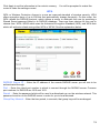
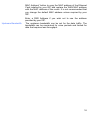
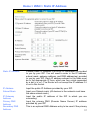
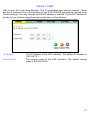
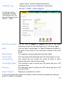
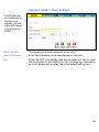
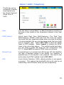
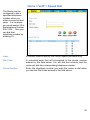
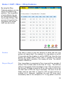
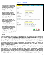
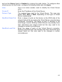
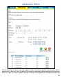
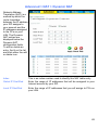
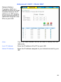
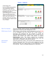
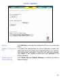
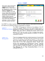
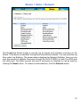
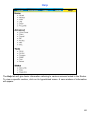
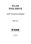
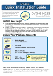
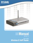
D-Link DVG-G1402S Wireless + 2Voice + 4SW VoIP Router Manual Building Networks for People Version B.1 Contents Package Contents........................................................................................................... 3 Introduction ..................................................................................................................... 4 Rear Panel Connections................................................................................................. 5 Front Panel LEDs ............................................................................................................ 6 Features ........................................................................................................................... 7 Installation ....................................................................................................................... 8 Using the Configuration Wizard .................................................................................... 9 Home > Wireless ......................................................................................................... 9 Home > Wireless ....................................................................................................... 10 Home > Wireless > Wireless LAN Authorization ....................................................... 11 Open Auth − Shared Key........................................................................................... 12 WPA......................................................................................................................... 13 WPA-PSK ................................................................................................................ 14 Home > WAN............................................................................................................. 15 Home > WAN > Static IP Address ............................................................................. 17 Home > WAN > PPPoE ............................................................................................. 19 Home > LAN .............................................................................................................. 21 Home > VoIP ............................................................................................................. 22 Home > VoIP > Provisioning...................................................................................... 25 Home > VoIP > STUN Configuration......................................................................... 26 Home > VoIP > User Agent ....................................................................................... 27 Home > VoIP > Peer to Peer ..................................................................................... 28 Home > VoIP > Telephony ........................................................................................ 29 Home > VoIP > Speed Dial........................................................................................ 30 Home > VoIP > Misc.................................................................................................. 31 Home > VoIP > Misc. > Ring Cadence...................................................................... 32 Home > VoIP > Misc. > Ring Default Rule ................................................................ 33 Home > VoIP > Misc. > Ring Rule............................................................................. 34 Home > VoIP > Manage Features > Reject Incoming Call........................................ 35 Home > VoIP > Manage Features > Block Outgoing Call ......................................... 36 Home > DHCP ........................................................................................................... 37 Home > Proxy DNS ................................................................................................... 39 Advanced > Virtual Server ......................................................................................... 40 Advanced > Filters ..................................................................................................... 42 Advanced > Filters > IP Filters................................................................................... 43 Advanced > Filters > MAC Filters ............................................................................ 44 Advanced > Firewall .................................................................................................. 45 Advanced > Routing > RIP Configuration.................................................................. 46 Advanced > Routing > Static Route .......................................................................... 47 Advanced > NAT > NAT Configuration...................................................................... 48 Advanced > NAT > Dynamic NAT ............................................................................. 49 Advanced > NAT > Static NAT .................................................................................. 50 Tools > Admin............................................................................................................ 51 Tools > System .......................................................................................................... 52 Tools > Firmware ....................................................................................................... 53 Tools > SNMP............................................................................................................ 54 Tools > Time .............................................................................................................. 55 Status > Device Info................................................................................................... 56 Status > Stats > Network ........................................................................................... 57 Status > Stats > Phone Call....................................................................................... 58 Status > Diagnostics .................................................................................................. 59 Help............................................................................................................................ 60 2 Package Contents • • • • • D-Link DVG-G1402S Router Power Adapter - AC 12V, 1.2A Manual and Warranty on CD Quick Installation Guide Ethernet Cable (All the Ethernet ports on DVG-G1402S are Auto-MDIX) Note: Using a power supply with a different voltage rating than the one included with the DVG-G1402S will cause damage and void the warranty for this product. If any of the above items are missing, please contact your reseller. • • • • • System Requirements for Configuration Ethernet-Based Cable or DSL Modem Computers with Windows, Macintosh, or Linux-based operating systems with an installed Ethernet adapter Computers with Windows, Macintosh, or Linux-based operating systems with an installed Ethernet adapter Internet Explorer Version 6.0 or Netscape Navigator Version 6.0 and Above 3 Introduction The D-Link DVG-G1402S High-Speed VoIP Router Links traditional telephony networks to IP networks with conventional telephony devices such as analog phones or fax machines. It can reduce long distance phone charges and deliver toll-quality voice communication over the IP network. This gateway provides two loop start Foreign Exchange Subscriber (FXS) ports and four LAN ports. One Ethernet port for a DSL/Cable Modem or other WAN devices, and the other for connection to create a home or small office LAN networks. The built-in DHCP server/client and Network Address Translation (NAT) function automatically assign IP address for LAN users, allowing multiple users to share a single Internet connection. It can be configured/monitored via the Console, Web browser, Telnet and HTTPS provisioning is also supported. 4 Rear Panel Connections Phone Connections Auto MDI/MDIX LAN Ports Factory Reset Button Connect to your phones using standard phone cabling. Connect the Ethernet cable from computers on your LAN to these ports. Pressing this button will restore the router to its factory default settings. All Ethernet Ports (WAN and LAN) are auto MDI/MDIX, meaning you can use either a straight-through or a crossover Ethernet cable. WAN Port Connect the Ethernet cable from your ADSL modem to this port. Power Adapter Connect your 12V 1.25A power adapter here. 5 Front Panel LEDs Status LED WAN LED Phone LEDs A blinking LED indicates the DVG-G1402S is functioning properly. An active LED indicates a link has been established. A blinking LED indicates activity on the WAN port. The Hook LED will light when a telephone is off the hook. A blinking LED indicates an incoming call is detected. Power LED A solid light indicates a valid connection to the power supply. LAN LEDs An active LED indicates a link has been established. A blinking LED indicates activity on the LAN port. 6 Features • • • • • • • • • • • • • • • • • • • 1 NWay 10/100BASE-TX Fast Ethernet port for WAN-connection 4 NWay 10/100BASE-TX Fast Ethernet port for LAN-connection 2 Foreign Exchange Subscriber (FXS) POTS ports (RJ-11 Jacks) Voice Activity Detection (VAD) /Comfort Noise Generation (CNG) Silence suppression to reduce bandwidth consumption. Adaptive jitter buffer for a smooth voice reception Lost packet recovery ability for improved voice quality Support QoS (Quality of Service) for voice quality guarantee. Build-in PPPoE function to support dial-up connection for broadband technology. IP address assignment using DHCP or static configuration RIP1/RIP2 and static routing support Support IP sharing to allow multiple users to access the Internet via a single IP address Support Caller ID function Configuration download using HTTPS and SSL/TLS client certificate encryption and authentication Support VPN Pass-Through MAC and Packet filter support Remote configuration and management over the Internet using web browsers Firmware backup support Support configuration backup and restore 7 Installation For a typical setup at home, please do the following: 1. You will need broadband Internet access (a Cable or DSL-subscriber line into your home or office) 2. Consult with your Cable or DSL provider for proper installation of the modem 3. Connect the Cable or DSL modem to the DVG-G1402S VoIP Router (see the printed Quick Installation Guide included with your router.) 4. Install the D-Link DFE-530TX+ adapter into a desktop computer. The four Ethernet LAN ports of the DVG-G1402S are Auto MDI/MDIX and will work with both Straight-Through and Cross-over cables. (See the printed Quick Installation Guide included with the DFE-530TX+.) 8 Using the Configuration Wizard Whenever you want to configure your network or the DVG-G1402S, you can access the Configuration Menu by opening the web-browser and typing in the IP Address of the DVG-G1402S. The DVG-G1402S default IP Address is shown to the right: • Open the web browser • Type in the IP Address of the Router (http://192.168.15.1) • Type admin in the User Name field • Type admin in the Password field • Click OK 192.168.15.1 The Home > Wizard screen will appear. Please refer to the Quick Installation Guide for more information regarding the Setup Wizard. These buttons appear on most of the configuration screens in this section. Please click on the appropriate button at the bottom of each screen after you have made a configuration change. Note: if you have changed the default IP Address assigned to the DVG-G1402S, make sure to enter the correct IP Address. Clicking this button will save configured settings to the router. Clicking Cancel will clear changes made to the current page. Clicking Help will provide the user with helpful information about the current window. Click refresh will refresh the statistics of the 9 current window. Home > Wireless Wireless LAN Usage This drop-down menu allows you to enable or disable the Wireless LAN feature on the DVG-G1402S. Wireless LAN Mode You can select between three IEEE WLAN standards − 802.11b/g, 802.11g, and 802.11b − depending upon which type of Wireless LAN devices you have. Channel What channels are available for use by the access point depends on the local regulatory environment. Remember that all devices communicating with the device must use the same channel (and use the same SSID). Use the drop down menu to select the channel used for your 802.11b wireless LAN. Rate Config SSID You can select between Long, Short, and Long and Short. Hidden SSID Enabling this feature will prevent the DVG-G1402S from broadcasting it’s SSID. Remote stations will have to have the router’s SSID manually entered to connect. Service Set Identifier (SSID) is the name designated for a specific wireless local area network (WLAN). The SSID’s factory default setting is default. The SSID can be easily changed to connect to an existing wireless network or to establish a new wireless network. 10 Home > Wireless > Wireless LAN Authorization Authentication This router employs three basic types of Authentication for access to the router’s wireless network, WEP, WPA, and WPA-PSK, which can be selected by clicking the corresponding radio button. No Auth will disable Wireless LAN authentication. Each selection will alter the window to accommodate the entry of the necessary keys. See the explanation below for more information. 11 Open Auth − Shared Key The Open Auth − Shared Key choice for Authentication will produce the screen shown above for the user’s configuration. The Open Auth choice is for general use and utilizes basic WEP encryption. The Shared Key choice is used between cooperating devices that share a common encryption key. WEP (Wireless Encryption Protocol or Wired Equivalent Privacy) encryption can be enabled for security and privacy. WEP encrypts the data portion of each frame transmitted from the wireless adapter using one of the predefined keys. Decryption of the data contained in each packet can only be done if the both the receiver and transmitter have the correct shared key. WEP – Click the Enabled radio button to employ WEP encryption on the router. Auth Method – Select Open Auth, Shared Auth, or Auto. Encryption Type – Use the pull-down menu to select the type of Key to be used for encryption. The user may choose HEX (Hexadecimal) or ASCII (American Standard Code for Information Interchange). Both will require the user to enter a key in the following field. Key field drop-down menu - Use the drop down menu to select the type of WEP encryption. Select 64 Bit to enable 64 bit Hexadecimal encryption, 128 Bit to enable 128 bit Hexadecimal encryption, 152 Bit to enable 152 bit Hexadecimal encryption. Key – The user may enter up to four keys to be used for encryption. Only the key selected using the corresponding radio button will be used for encryption. 12 Click Apply to set the information in the router’s memory. router to make the settings current. You will be prompted to restart the WPA WPA or Wireless Protection Access is a new an improved standard of wireless security. WPA offers encryption keys of up to 256-bits that automatically change frequently. On this router, the WPA utilizes the RADIUS protocol, which utilizes a server to authorize the user by matching a Shared Secret password listed in its RADIUS database. There are three choices for the user to choose from. WPA, WPA2 which uses the Advanced Encryption Standard (AES), and WPA-Auto which will authorize clients using either WPA or WPA2. See the explanation below. RADIUS Server IP – Enter the IP address of the remote RADIUS server you will use to be authenticated through. Port – Enter the virtual port number to which to connect through the RADIUS server. Common port numbers for RADIUS are 1812 and 1813. Secret – Enter the password which will be used to authenticate you on the wireless network. This password must be on the RADIUS server in order for you to be authorized. Group Key Interval – Enter the time period, in seconds, that group keys will be exchanged. 13 WPA-PSK WPA-PSK (Pre-Shared Key) uses the same encryption as the WPA but is implemented differently. All devices on the wireless network share the same key (Passphrase) to activate the WPA security. There are three choices for the user to choose from. WPA-PSK, WPA2-PSK which uses the Advanced Encryption Standard (AES), and WPA-PSK-Auto which will authorize clients using either WPA or WPA2. To utilize, select one of the previous choices, enter the Passphrase, confirm it in the second field and click Apply. 14 Home > WAN Dynamic Choose Dynamic IP Address to obtain IP Address information automatically from your ISP. This option should be selected if your ISP has not supplied you with an IP address. This option is commonly used for Cable modem services. Host Name The Host Name is optional but may be required by some ISPs. The default host name is the device name of the Router and may be changed. MAC Address The default MAC Address is set to the WAN’s physical interface MAC address on the Broadband Router. It is not recommended that you change the default MAC address unless required by your ISP. Clone MAC Address The default MAC address is set to the WAN’s physical interface MAC address on the Broadband Router. You can use the “Clone 15 MAC Address” button to copy the MAC address of the Ethernet Card installed by your ISP and replace the WAN MAC address with the MAC address of the router. It is not recommended that you change the default MAC address unless required by your ISP. Upstream Bandwidth Enter a DNS Address if you wish not to use the address provided by your ISP. The upstream bandwidth can be set for the data traffic. The bandwidth can be maximized for voice packets and limited for data that requires less throughput. 16 Home > WAN > Static IP Address Static IP Address Choose Static IP Address if all WAN IP information is provided to you by your ISP. You will need to enter in the IP address, subnet mask, gateway address, and DNS address(es) provided to you by your ISP. Each IP address entered in the fields must be in the appropriate IP form, which are four octets separated by a dot (x.x.x.x). The Router will not accept the IP address if it is not in this format. IP Address Subnet Mask Input the public IP Address provided by your ISP. Input your Subnet mask. (All devices in the network must have the same subnet mask.) Input the public IP address of the ISP to which you are connecting. Input the primary DNS (Domain Name Server) IP address provided by your ISP This is an optional DNS Address entry to be used if the primary IP Gateway Address Primary DNS Address Secondary DNS Address 17 Upstream Bandwidth DNS Fails. The upstream bandwidth can be set for the type of packets that the will be sent. The bandwidth can be maximized for voice packets and limited for data that requires less throughput. 18 Home > WAN > PPPoE Choose PPPoE (Point to Point Protocol over Ethernet) if your ISP uses a PPPoE connection. Your ISP will provide you with a username and password. This option is typically used for DSL services. PPPoE Choose this option if your ISP uses PPPoE. (Most DSL users will select this option.) Password Retype Password Service Name IP Address Enter The PPPoE user name provided to you by your ISP. Retype the password entered in the previous field. Enter the Service Name provided by your ISP (optional). This option is only available for Static PPPoE. Enter the static IP Address for the PPPoE connection. MAC Address The default MAC Address is set to the WAN’s physical interface MAC address on the Broadband Router. It is not recommended that you change the default MAC address unless required by your ISP. 19 Primary DNS Address Secondary DNS Address Upstream Bandwidth Input the primary DNS (Domain Name Server) IP address provided by your ISP This is an optional DNS Address entry to be used if the primary DNS fails. The upstream bandwidth can be set to suit the type of packets that the connection will be sending. The bandwidth can be maximized for voice packets and limited for data that requires less throughput. 20 Home > LAN LAN is short for Local Area Network. This is considered your internal network. These are the IP settings of the LAN interface for the DVG-G1402S and may be referred to as Private settings. You may change the LAN IP address if needed. The LAN IP address is private to your internal network and cannot be seen on the Internet. IP Address Subnet Mask The IP address of the LAN interface. The default IP address is 192.168.15.1. The subnet mask of the LAN interface. The default subnet mask is 255.255.255.0. 21 Home > VoIP All of the screens necessary to setup and configure the router to handle VoIP traffic are accessed from the screen shown below. To access any of the individual configuration screens, click on the corresponding radio-button and that screen will appear. 22 Home > VoIP > Server Configuration The Router can be configured to handle voice signals over the Internet Protocol (Voice over IP − VoIP). The screen shown to the right, along with those on the following pages are used to configure your router to communicate with the devices that will send and receive telephone calls over the Internet. 23 Server FQDN Use this drop-down menu to Enable or Disable the Server Fully Qualified Domain Name (FQDN) function. This is disabled when the SIP URL domain name is different from the SIP proxy server domain name. The phone will then use the domain name in Domain Name field as part of SIP URL but send and receive SIP messages through the SIP proxy server defined in the Service Domain field. IP Address Enter the IP address of the SIP Server in this field. Domain Name Enter the domain name corresponding to the IP address entered above in this field. Port Enter the SIP server’s listening port for the SIP in this field. Leave this field set to the default if your VoIP service provider did not give you a server port number for SIP. Secondary SIP Server The Secondary Features (FQDN, IP address, domain name and port), act as a backup for the initial connections’ settings. In the event that the connection with the SIP server is lost, the backup settings will be used. Outbound Proxy The Outbound Proxy is a normal SIP proxy. If instructed to do so by your ISP, enable the Outbound Proxy, and enter its IP address, Domain Name and Port Number in the appropriate fields. Service Domain Enter the SIP service domain name in this field. URL Format Select SIP-URL to have the router include the domain name with the SIP number in the SIP messages that it sends. Select TEL-URL to have the router use the SIP number without a domain name in the SIP messages that it sends. User Parameter You can set this to phone or none. This determines whether or not the phone number is appended to the information forwarded to your SIP server. Your VoIP service provider will instruct you which setting to use. Caller ID Delivery Use this pull-down menu to initiate the delivery of the inbound caller ID. Display CID Use this pull-down menu to enable or disable the display of the Caller ID. Timer T2 Set the timer to 4, 8, 16 or 32. Initial Unregister Enable or disable the initial unregister. Register Expiration Use this field to set how long the router will wait before sending a repeat registration request if a registration attempt fails or there is no response from the registration server. 24 Home > VoIP > Provisioning Provisioning is a function that automatically updates your DVG-G1402S’s VoIP configuration by using a TFTP server located on the Internet. If you have accesses to such a service, you will need to know the URL and Proxy Address of the Provisioning Server. Provisioning Function Use this drop-down menu to Enable or Disable the Provisioning Function on the router. Server URL Enter the URL of the Provisioning Server in this field. Proxy Address Enter the IP address of the Proxy Server in this field. Proxy Port Number Enter the port number the Proxy Server will use to make the connection in this field. 25 Home > VoIP > STUN Configuration Simple Traversal of UDP over NAT (STUN) − is a protocol which enables a VoIP device, such as this router or an IP phone, to detect the presence and type of NAT behind which the phone is placed. This router supports STUN and can intelligently modify the private IP address and port in its SIP/SDP message by using the NAT mapped public IP address and port through a series of STUN queries against a STUN server located on the public Internet. This will allow SIP signaling and RTP media to successfully traverse a NAT without requiring any configuration changes on the NAT. STUN is useful if you need to use the DVG-G1402S behind a modem or router that provides the connection to your ISP and then to the Internet and does not support symetric NAT. You will need access to a STUN server on the Internet and its IP address to use STUN on the DVG-G1402S. STUN State Use this drop-down menu to Enable or Disable STUN on the router. STUN Server IP Address Enter the IP address of a STUN server in this field. STUN Server Port Enter the port number the STUN server will use in this field. If you do not have any information as to the proper port number, leave the default setting here. STUN ReqInterval This determines the amount of time, in seconds, between STUN requests. If you do not have any information as to the 26 proper interval, leave the default setting here. STUN NAT Type Displays the result of the STUN NAT examination. Home > VoIP > User Agent The Router can be configured to handle voice signals over the Internet Protocol (Voice Over IP − VOIP). Same Phone Number Use this field to Enable or Disable the use of the same telephone number for the User Agent as for the Server Agent. Index Use this field to assign line 1 or line 2 telephone sockets (on the back of the router) to the information entered in the User Agent. Phone Number The telephone number assigned to the User Agent. Domain Name The name that will be displayed when the User Agent is in use. User Agent Port This selects the port number the router will listen to when determining when calls are being made. Authentication Name The Username used to access your SIP server and your VoIP service provider. Password The Password used to access your SIP server and your VoIP service provider. Retype Password Retype your password to confirm. To query the registration state of click Query. When the server responds you have the option to register or unregister. 27 Home > VoIP > Peer to Peer The Router can be configured to handle voice signals over the Internet Protocol (Voice Over IP − VOIP). Phone Number The telephone number assigned to this entry. User IP Address Enter the IP address of the remote peer in this field. Port Enter the UDP port number the remote peer will use to make the connection in this field. If you do not have any information as to the proper port number, leave the default setting here. 28 Home > VoIP > Telephony The Router can be configured to handle voice signals over the Internet Protocol (Voice Over IP − VoIP). Index Use this field to assign line 1 or line 2 telephone sockets (on the back of the router) to the information entered in the User Agent. DTMF Method Out-of band Dual Tone Multi-frequency -The Dual Tone Multi-frequency (DTMF) mode sets how the router will handle the tones that your telephone makes when you push its buttons. It is recommended that you use the same mode that your VoIP service provider uses. Select RFC 2833 to send the DTMF tones in RTP packets. Select Inband to include the DTMF tones in the voice data stream. This method works best when you are using a codec that does not use compression (like G.711). Select INFO to transmit DTMF tones out-of-band. Payload Type A payload type is a number from 96 through 127 that identifies the type of payload carried in the packet. For example, a payload type of 122 denotes a fax payload. This field is only active when the DTMF method is set to RFC 2833. VAD Voice Activity Detection (VAD) -detects whether or not speech is present. This reduces the bandwidth that a call uses by not transmitting “silent Packets” when you are not speaking. 29 Home > VoIP > Speed Dial The Router can be configured to dial a specified telephone number when you enter a numerical dial code. For example, you could assign 22 to the telephone number 555-1234. Then you can dial that telephone number by entering 22. Index A number used to identify the current speed dial table entry. Dial Code A numerical code that will correspond to the phone number entered in the field below. You will dial this number, and the router will dial the corresponding telephone number. Phone Number Enter the telephone number you want the router to dial when you dial the Dial Code entered in the field above. 30 Home > VoIP > Misc. Instead of adding additional lines to handle different telephone numbers, distinctive rings can be set to allow more than one telephone number to reach the same line. Calls coming in on different numbers on the same line can be identified by their distinctive ring pattern. For example, you could set a “short-short” ring for the sales department number, and a regular ring for the technical support number. Use the radio button to select Ring Cadence, Ring Default Rule, or Ring Rule. These three features allow the user to set distinctive rings. To configure distinctive rings, see the descriptions of the three features below. 31 Home > VoIP > Misc. > Ring Cadence By using the Ring Cadence window, you can set up to 8 distinct ring patterns. The ring pattern of each distinct ring can be configured by setting the On and Off time. The amount of times that the ring pattern will repeat itself can also be set. Duration This field is used to limit the amount of times that the ring pattern will repeat itself. For example, if a ring pattern is set for 16 seconds and the duration is set for 60000 ms, then the ring pattern will repeat itself 3 times; then, 3 quarters of the way through the fourth repetition, the ringing will stop. The default value is 180000 ms. Ring on Ring off One ring pattern is comprised of four rings and four periods of silence. The On field refers to the time of 1 ring. The Off time refers to the period of silence between rings. One unit of time in the On and Off fields is equal to 50 ms; so a value of 40 in the On field sets a 2000 ms ring (2 seconds). The sum of all the fields must be less than or equal to 320 ms and must be a multiple of 8. However, individual On and Off times don’t necessarily have to be multiples of 8. A ring pattern could be 32 set at 12, 12, 8, 4, 10, 50, 0, 0. While some of the On and Off times are not multiples of 8, their sum of 96 meets the requirement so this would be a valid ring pattern. Home > VoIP > Misc. > Ring Default Rule The Ring Default Rule is set for inbound callers that are not defined by the Ring Rule. One Ring Default Rule can be set for each VoIP port. Ring Cadence Profile ID Use this pull-down menu to select a Ring Cadence for the Ring Default Rule. The 8 different Ring Cadences can be configured on the Ring Cadence window. 33 Home > VoIP > Misc. > Ring Rule You can use the Ring Rule window to assign Caller IDs to frequently received inbound calls. Any call that has been assigned a caller ID will have its ID number displayed on the receiver’s caller display. This way, the receiver knows which department the inbound call is attempting to reach by the ring cadence, and who the caller is by the caller ID. From Port Ring Cadence Profile ID Caller ID Use the From field to select either VoIP or PSTN. Use the Port field to select either Port 1 or Port 2. You can also choose both ports 1 and 2. Use this pull-down menu to select a Ring Cadence for the Ring Rule. The 8 different Ring Cadences can be configured on the Ring Cadence window. Set a numerical Caller ID of up 32 digits. 32 caller IDs can be created and will be listed below the Ring Rule Configuration area. To edit or delete an entry that has already been created, find the entry in the list and click on the appropriate icon. 34 Home > VoIP > Manage Features > Reject Incoming Call You can configure the router to reject incoming calls from particular telephone numbers by entering the telephone number in the screen shown below. Name PhoneNum Enter a name to identify the current entry. Enter the telephone number you want to block incoming calls from. 35 Home > VoIP > Manage Features > Block Outgoing Call You can configure the router to reject outgoing calls from particular telephone numbers by entering the telephone number in the screen shown below. Name PhoneNum Enter a name to identify the current entry. Enter the telephone number you want to block outgoing calls to. 36 Home > DHCP Dynamic Host Configuration Protocol (DHCP) allows the gateway to automatically obtain the IP address from a DHCP server on the service provider’s network. The service provider assigns a global IP address from a pool of addresses available to the service provider. Typically the IP address assigned has a long lease time, so it will likely be the same address each time the Router requests an IP address. If DHCP is not enabled on the Router, it is necessary for the user to assign a static IP address to each computer on your LAN. To setup DHCP for your LAN, first enable the Router as a DHCP server by clicking the corresponding Enabled radio button in the window above. The next step is to set a range of IP addresses that you wish to allot to the devices on your LAN by entering a Starting IP Address and an Ending IP Address. This may be in a range from 2 to 254 (192.168.1.2 – 192.168.1.254). Computers on your LAN will have an IP address within this range then automatically assigned to them. Finally, enter the Lease Time, which is the time the Server will set for devices using DHCP to re-request an IP Address. Clients authorized for DHCP will be listed in the table at the bottom of the page. Click Apply to implement information set in this table. The DHCP Server is enabled by default. DHCP may also be statically configured as well. This method allows the router to assign the same IP address information to a specific computer on the network, defined by its MAC address. This computer will get the same DHCP implemented IP address information every time the computer is turned on and this IP address will be specific to that computer’s IP address on the local network. No other computer can be assigned this address. This is useful for computers on the LAN that are hosting applications such as HTTP or FTP. First, the user must enable the Static DHCP function by clicking the 37 corresponding Enabled radio button. Next the user must enter the host name and the IP address for that computer by entering the last numbers into the space provided in the IP Address field. Next, the user is to enter the MAC address of the computer into the space provided. Click Apply to implement these static settings. The DHCP Client field will allow users to Clone the settings from their computer that were learned from the DHCP server. Simply use the pull down menu to select the MAC address of the computer to be cloned and then click the Clone button. The settings from this computer will be implemented in the Static DHCP configuration area. Click Apply to implement these static settings. The lower portion of the window contains the Static DHCP icon to edit an entry and on the icon to delete an Configuration List. Click on the entry. 38 Home > Proxy DNS State Use this drop down menu to enable or disable the Proxy DNS. Proxy DNS IP Address Enter the IP Address of the Proxy DNS. 39 Advanced > Virtual Server To view the following window, click on the Advanced tab at the top of the window and then click the Virtual Server button to the left. The Virtual Server will allow remote users access to various services outside of their LAN through a public IP address, such as FTP (File Transfer Protocol) or HTTPS (Secure Web). After configuring the Router for these features, the Router will redirect these external services to an appropriate server on the user’s LAN. These external services may be modified by clicking its corresponding edit icon, or they may be deleted by clicking the corresponding delete icon. Though there are seven fields available to configure the Virtual Server, in most cases, only the IP address of the Virtual Server will be needed for implementation. To enable an already existing Virtual Server, click its corresponding edit button, configure the appropriate fields listed below 40 and set the Status fields to Enabled by clicking the radio button. To configure other virtual servers for the Router, configure the following fields and click Apply. Index Private IP Protocol Type Start/End Global Port Start/End Local Port This is an index number used to identify the Virtual Server entry. Enter the IP address of the Virtual Server. The protocol type used for the Virtual Server. The user may select TCP, UDP or Both, depending on the type of Virtual Server implemented. Enter a range of ports on the device on the WAN side of the network that will be accessing the Virtual Server currently being configured. Commonly, this range of ports is identical to the local range of ports. Existing Virtual Servers may already have their well-known port ranges listed but this may need to be changed in certain circumstances. Enter the range of ports of the Virtual Server’s computer. Existing Virtual Servers may already have their well-known port ranges listed but this may need to be changed in certain circumstances. 41 Advanced > Filters Packet filtering is a basic security measure that should be used on any network that is exposed to a security risk. A packet filter system examines data packets and scrutinizes them in order to control network access. Filtering rules determine whether packets are 42 passed through the Router from either side of the gateway. The rules are created and controlled by the network administrator and can be precisely defined. These rules are used to block access to the LAN from outside the network and/or to deny access to the WAN from within the network. The Router uses filtering rules to examine data packet headers for specific information. Packets passing through the Router that do not meet the criteria specified by the rule set are dropped. Effective implementation of packet filtering requires detailed knowledge of network services and communication protocols. An overly complicated filtering scheme can adversely affect the Router’s performance, while an inadequate set of rules may needlessly compromise security. This Router has two fields to configure for filtering which are IP Filters and MAC Filters. Advanced > Filters > IP Filters This window will aid the use in configuring filters for IP addresses. This will deny specified LAN IP addresses or specific ports associated with these LAN IP address from accessing the Internet. Well known ports have already been previously set in the IP Filters List and can be modified by clicking their corresponding edit icon, and simple adding an IP address to the configuration. To access this screen, click the Advanced tab along the top of the configuration window 43 and then the Filters tab to the left hand side. Protocol The protocol associated with this IP filter. The user may choose between TCP, UDP or Both. IP Address An IP address or range of IP addresses that will be denied access to the Internet. Subnet Mask The subnet mask that corresponds to the IP address above. Start Port/End Port A port or range of ports that will be denied access to the Internet. If no port is entered, all ports in this IP range will be denied access to the Internet. Advanced > Filters > MAC Filters All computers are uniquely identified by their MAC (Media Access Control) address. The following window will allow users to deny computers access to the Internet or only allow certain computers access to the Internet, based on their MAC address. To access this screen, click the Advanced tab along the top of the configuration window, then the Filters tab to the left hand side and finally click the corresponding radio button for MAC Filters. Index MAC Address State A number used to identify this MAC address filter setting. Enter the MAC address to be filtered. This field allows you to enable or disable this MAC address filter setting. 44 Advanced > Firewall This Router comes equipped with a firewall. The Firewall configuration screen allows the Router to enforce specific predefined policies intended to protect against certain common types of attacks. To configure the Router’s firewall, click the Advanced tab at the top of the screen and then the Firewall tab to the left. Pass or Block Select the action you want the filter to take when it finds a packet that meets the criteria entered below. Protocol The protocol associated with this IP filter. The user may choose between TCP, UDP or Both. Source Enter the IP address or range of IP addresses that you wish to block or allow to pass through the router. The Source may be identified on the LAN side, the WAN side or both by using the pull-down menu for the Interface heading. Destination Enter the IP address or range of IP addresses that you wish to deny or allow access to the Internet. The Destination may be identified on the LAN side, the WAN side or Both by using the pull-down menu for the Interface heading. The type of protocol may also be chosen by using the pull-down menu. The user 45 may choose between TCP, UDP, ICMP or (*) Any. The user may also select a range of ports of the destination IP addresses by entering the range under the Port Range heading. Subnet Mask The subnet mask that corresponds to the IP address above. Advanced > Routing > RIP Configuration RIP − Routing Information Protocol − specifies how routers exchange information. With RIP, routers occasionally exchange entire routing tables. You can select RIPv1 or RIPv2 by clicking the radio button under the Version heading, and then select On or Off by clicking the radio button under the State heading. LAN RIPv1 Select RIPv1 or RIPv2 for use by the router on your LAN. LAN RIPv2 Select RIPv1 or RIPv2 for use by the router on your LAN. WAN RIPv1 Select RIPv1 or RIPv2 for use by the router on the WAN. WAN RIPv2 Select RIPv1 or RIPv2 for use by the router on the WAN. State Select On or Off to enable or disable RIP on either the LAN or the WAN 46 Advanced > Routing > Static Route The Routing table, shown to the right, allows you to enter static routes between computers on both the WAN (Internet) and your LAN. IP Address Enter the IP Address of the subnet or device where packets are to be routed. Subnet Mask Enter the subnet mask corresponding to the IP address entered above. Gateway Enter the IP address of the gateway used for packets that are to be routed to the IP address entered above. Interface Select the WAN (Internet) or LAN interface. Metric Enter the number of hops (the number of routers) that packets will be allowed to cross when being routed to the IP address entered above. State Use this drop-down menu to Enable or Disable this route. 47 Advanced > NAT > NAT Configuration Network Address Translation (NAT) is a method by which the router translates between the IP address your ISP assigns to your account and the IP addresses assigned to the PCs on your LAN. NAT Interface IP Address This field displays the current IP address of the LAN side of the router. All IP address that are translated by the router will be in the same range as this IP address. NAT Interface Netmask This field displays the subnet mask corresponding to the IP address displayed above. NAT Function Use this pull-down menu to enable or disable NAT on the router. 48 Advanced > NAT > Dynamic NAT Network Address Translation (NAT) is a method by which the router translates between the IP address your ISP assigns to your account and the IP addresses assigned to the PCs on your LAN. The Dynamic NAT entries are displayed below the Dynamic NAT configuration fields. To edit or delete an entry, find it on the list and click either the edit or delete icon. Index This is an index number used to identify this NAT table entry. Global IP Start/End Enter the range of IP addresses that will be assigned to your Internet account by your ISP. Local IP Start/End Enter the range of IP addresses that you will assign to PCs on your LAN. 49 Advanced > NAT > Static NAT Network Address Translation (NAT) is a method by which the router translates between the IP address your ISP assigns to your account and the IP addresses assigned to the PCs on your LAN. Index This is an index number that will be used to identify this NAT table entry. Local IP Address Enter the IP address of the PC on your LAN. Global IP Address Enter the IP address assigned to your Internet account by your ISP. 50 Tools > Admin At this page, the DVG-G1402S administrator can change the system password. There are two accounts that can access the Broadband Router’s Web-Management interface. They are admin and user. Admin has read/write access while user has read-only access. User can only view the settings but cannot make any changes. Web Port Number WAN Access Control Administrator Password The port number used to access the Broadband Router. The default port number for web management is 80. WAN access control allows remote management via the DI-624 to be configured from the Internet by a web browser. A username and password are still required to access the Web-Management interface. In general, only a member of your network can browse the built-in web pages to perform Administrator tasks. This feature enables you to perform Administrator tasks from the remote (Internet) host. Click the radio button to Enabled to activate this feature. Enter the password, admin, here and the same password in the Confirm Password field. This will be the password that the administrator will use to gain access to the configuration menu of the device. There is no default password for this device. 51 Tools > System Backup Click Backup to backup the configuration file to your local hard drive. Restore Configuration File To restore the configuration file click on Browse to search the local hard drive and locate the configuration file to be used for the configuration restoration. Once the file has been located, click Open in the browser window and then Upload on the System window. Restore Factory Default Settings Click Reset Factory Default Settings to restore the factory default settings. 52 Tools > Firmware You can update both the software and firmware of the Router. Please check the D-Link Support site for firmware updates at http://support.dlink.com. You can download firmware upgrades to your hard drive from the D-Link support site. Software Update Enter the TFTP server address. Firmware Update Click Enabled to begin the firmware update. File Name Enter the firmware file name and DOS path in this field. For example, C:\firmware.had 53 Tools > SNMP This menu can be accessed directly by clicking on the SNMP button or hyperlink in the Tools setup menu. Simple Network Management Protocol (SNMP) is an OSI Layer 7 Application designed specifically for managing and monitoring network devices. SNMP enables network management stations to read and modify the settings of gateways, routers, switches, and other network devices. Use SNMP to configure system features for proper operation, performance monitoring, and detection of potential problems in the Router or network. The SNMP IP Management Address is the address of the PC SNMP IP running the SNMP software from the DVG-G1402S device. A Management Address defined set of variables (managed objects) is maintained by the SNMP agent and used to manage the device. Enter the IP address of PC that you want to use to manage the network. You may also enter a backup address of another PC that can manage the network. SNMP Trap Management Traps are messages that alert network personnel of events that occur on the Switch. The events can be as serious as a reboot (someone accidentally turned OFF the Switch), or less serious like a port status change. The Router generates traps and sends them to the trap management server. Typical traps include trap messages for Authentication Failure, Topology Change and Broadcast/Multicast Storms. Use the pull-down menu to enable or disable the SNMP on the device. Enter the Trap Manager IP and Trap Community Name of the trap management server. 54 Tools > Time The system time is the time used by the DVG-G1402S for scheduling services. You can manually set the time, connect to a NTP (network time protocol) server or synchronize the time on the router with your PC. If an NTP server is set, you will only need to set the time zone (in the set up wizard). 55 Status > Device Info This page displays the current information for the DVG-G1402S. It will display the LAN, WAN, Disk Information statistics. This window will show the DVG-G1402S’s working status: WAN LAN IP Address: WAN/Public IP Address Subnet Mask: WAN/Public Subnet Mask Default Gateway: WAN/Public Gateway IP Address LAN MAC Address: MAC address of the DVG-G1402S IP Address: LAN/Private IP Address of the DVG-G1402S Subnet Mask: LAN/Private Subnet Mask of the DVG-G1402S 56 Status > Stats > Network The Broadband Router keeps a running log of events and activities occurring on the Router. If the device is rebooted, the logs are automatically cleared. You may save the log files under Log Settings. The screen above displays the Network Statistics. Here you can view the amount of packets that pass through the DVG-G1402S on both the WAN and the LAN ports. The traffic counter will reset if the device is rebooted or can be reset by clicking the Reset button. To refresh current statistics, click the Refresh button. 57 Status > Stats > Phone Call 58 The Broadband Router keeps a running log of events and activities occurring on the Router. If the device is rebooted, the logs are automatically cleared. You may save the log files under Log Settings. The screen above displays the Phone Statistics. Here you can view the amount of packets that pass through the DVG-G1402S on both Phone 1 and Phone 2 ports. The traffic counter will reset if the device is rebooted or can be reset by clicking the Reset button. To refresh current statistics, click the Refresh button. Status > Diagnostics The Diagnostics window allows users to test the functionality of the router by executing a ping test. Enter the IP address of the Ping Target and then click Test. 59 Help The Help tab will give basic information referring to various screens locted in the Router. To view a specific section, click on its hyperlinked name. A new window of information will appear. 60 Technical Specifications Standards IEEE 802.3 IEEE 802.3u VPN Pass Through/ Multi-Sessions PPTP L2TP I PSec Device Management Web-Based- Internet Explorer v6 or later; Netscape Navigator v6 or later; or other Java-enabled browsers DHCP Server and Client Advanced Firewall Features NAT with VPN Passthrough (Network Address Translation) MAC Filtering IP Filtering URL Filtering Domain Blocking Scheduling Operating Temperature 32ºF to 131 ºF (0ºC to 55ºC) Humidity: 95% maximum (non-condensing) Safety and Emissions: FCC 61 Technical Specifications LEDs: Power WAN LAN (10/100) Phone Status Physical Dimensions: L = 7.56 inches (192mm) W = 4.65 inches (118mm) H = 1.22 inches (31 mm) Power Input: Ext. Power Supply DC 12V, 1.5A Weight: 10.8 oz. (0.3kg) Warranty: 3 year (depends on D-Link global warranty policy) 62 Technical Support You can find software updates and user documentation on the D-Link website. D-Link provides free technical support for customers within the United States and within Canada for the duration of the warranty period on this product. U.S. and Canadian customers can contact D-Link technical support through our website, or by phone. Tech Support for customers within the United States: D-Link Technical Support over the Telephone: (877) 453-5465 24 hours a day, seven days a week D-Link Technical Support over the Internet: http://support.dlink.com email:[email protected] Tech Support for customers within Canada: D-Link Technical Support over the Telephone: (800) 361-5265 Monday to Friday 7:30am to 12:00 am EST D-Link Technical Support over the Internet: http://support.dlink.ca email:[email protected] 63