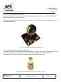
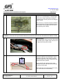
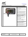
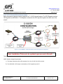
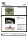
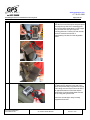
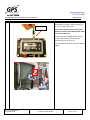
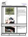
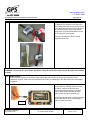
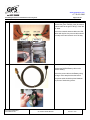
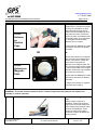
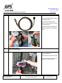
1
www.gpssource.com +1 719-561-3680 The WarFighter Source for GPS Retransmission Systems Page 1 of 102 Installation & Operational Manual For GLI-COBRA GPS Retransmission System Document Class/Number: DOC-UMN-AAA-AD GLI-COBRA USERS MANUAL Revision: 001F www.gpssource.com +1 719-561-3680 The WarFighter Source for GPS Retransmission Systems Page 2 of 102 Table of Contents 1.0 Introduction.................................................................................................................................................................................................................. 3 2.0 System Description...................................................................................................................................................................................................... 3 2.1 Component List ...................................................................................................................................................................................................... 5 2.2 Kit Contents ............................................................................................................................................................................................................ 6 2.3 Signal Conditioner .................................................................................................................................................................................................. 8 2.4 GPS Retransmission Antennas ............................................................................................................................................................................. 10 2.5 Signal Conditioner Output Terminators ................................................................................................................................................................. 10 2.6 GPS Receive Antenna .......................................................................................................................................................................................... 11 2.7 Mounting Hardware .............................................................................................................................................................................................. 11 3.0 Input Power Requirements ........................................................................................................................................................................................ 12 4.0 GPS Input Signal Requirements ................................................................................................................................................................................ 12 5.0 Signal Conditioner Mounting Requirements ............................................................................................................................................................... 12 6.0 Installation Instructions .............................................................................................................................................................................................. 13 6.1 CASA Installation Instructions ............................................................................................................................................................................... 13 6.2 C-17 Installation Instructions ................................................................................................................................................................................. 27 6.3 C-130J Installation Instructions ............................................................................................................................................................................. 36 6.4 C-130 E/H Installation Instructions ........................................................................................................................................................................ 45 6.5 C-27J Installation Instructions ............................................................................................................................................................................... 54 6.6 Ground Vehicle Installation Instructions ................................................................................................................................................................ 66 7.0 ECHO II System Operation: ....................................................................................................................................................................................... 77 7.1 Button Functions ................................................................................................................................................................................................... 79 7.2 L2 Offset Mode ..................................................................................................................................................................................................... 81 7.3 User Input Display, XMIT Light, and FAULT light .................................................................................................................................................. 82 8.0 System Checkout ...................................................................................................................................................................................................... 83 9.0 Fault Isolation ............................................................................................................................................................................................................ 85 10.0 Air Worthiness Certifications .................................................................................................................................................................................... 96 10.1 C-17 AMC: .......................................................................................................................................................................................................... 97 10.2 C-130J ................................................................................................................................................................................................................ 99 10.3 C-130E/H.......................................................................................................................................................................................................... 101 Document Class/Number: DOC-UMN-AAA-AD GLI-COBRA USERS MANUAL Revision: 001F www.gpssource.com +1 719-561-3680 The WarFighter Source for GPS Retransmission Systems Page 3 of 102 1.0 Introduction The GLI-COBRA is a Roll-on/Roll-off GPS Re-transmission System that provides GPS signals inside of an aircraft in support of modern GPS guided Precision Airborne and Airdrop missions. The GLI-COBRA system is compatible with any small to large transport aircraft and ground vehicles, including the: CASA, all variants of the C-17, C-130, CH-47, CH-53, C-27, and H-60. When installed in a vehicle, the GLI-COBRA provides reliable GPS coverage throughout the entire cargo compartment on smaller aircraft/vehicle and optional localized coverage on larger aircraft/vehicle, allowing any carry on military or commercial GPS receiver to operate inside the aircraft. With the GPS Retransmission System installed, the GPS guidance units can acquire satellite signals inside the aircraft negating the prolonged “time to first fix” delay upon deployment of the payload or airborne soldier. The system features 100% BIT coverage allowing each hardware component to be monitored, confirming that the system is fully operational and providing complete system fault isolation to the item level in the event of a system failure. In addition the system provides verification of the GPS signal’s strength, quality, and coverage allowing the aircrew to focus on the critical mission at hand. GLI-COBRA is packaged in a rugged portable case that can stand up to any demanding military mission. 2.0 System Description The GLI-COBRA GPS Retransmission System Signal Conditioner receives the composite L1/L2 GPS signal from the either the host aircraft’s GPS antenna system, or from a 2.6” active antenna that is included in the kit and that is usually placed on the flight deck. The Signal Conditioner Line Replaceable Unit (LRU) filters, amplifies, monitors, and distributes the L1/L2 GPS signal throughout the aircraft. The signal is distributed by way of a coaxial cable and retransmission antenna network. The antenna network includes up to 4 retransmission channels. Document Class/Number: DOC-UMN-AAA-AD GLI-COBRA USERS MANUAL Revision: 001F www.gpssource.com +1 719-561-3680 The WarFighter Source for GPS Retransmission Systems Page 4 of 102 Figure 1. GLI-COBRA GPS Retransmission System Block Diagram Document Class/Number: DOC-UMN-AAA-AD GLI-COBRA USERS MANUAL Revision: 001F www.gpssource.com +1 719-561-3680 The WarFighter Source for GPS Retransmission Systems Page 5 of 102 2.1 Component List The GLI-COBRA GPS Retransmission System consists of the following system components: o o o o o o o o o o o Signal Conditioner (SC) (1 ea.) GPS Retransmission Antennas (2 ea.) Signal Conditioner Output Terminators (4 ea.) GPS Receive Antenna (2 ea.) Mounting Hardware Passive Antenna Adjustable Hinge Mount (2 ea.) Receive Antenna Adjustable Hinge Mount (1 ea.) Receive Antenna Universal Mount Plate (1 ea.) Universal Foam Mount Adapter (2 ea.) Universal Velcro Mount Adapter (3 ea.) Universal Magnetic Mount Adapter (2 ea.) ECHOII Universal Velcro Mount Adapter (1 ea.) ECHOII Universal Foam Mount Adapter (1 ea.) ECHOII Universal Magnetic Mount Adapter (1 ea.) ECHOII Universal Adapter Mount plate with fasteners (1 ea.) Nylon Mounting Strap (3 ea.) Signal Conditioner Input Coaxial Cable (1 ea.) Receive Antenna Output Coaxial Cable (2 ea.) Transmit Antenna Input Coaxial Cable (2 ea.) Signal Conditioner Output Coaxial Cables (2 ea.) BA5590 Power Cable with Velcro securing strap (1 ea.) Optional Equipment C130 Power Cable 28VDC C-17 Power Cable 28VDC The GLI-COBRA kit may be ordered with, or upgraded to, the “Additional Two Antenna” option, bringing the total number of retransmission antennas in the kit to four. This enables 100% coverage of the cargo compartment in larger aircraft, such as the C-130J or the C-17A. The “Additional Two Antenna” option includes the following additional systems components: o o o o GPS Retransmission Antennas (2 ea.) Transmit Antenna Input Coaxial Cable (2 ea.) Signal Conditioner Output Coaxial Cables (2 ea.) Mounting Hardware Passive Antenna Adjustable Hinge Mount (2 ea.) Universal Foam Mount Adapter (2 ea.) Universal Velcro Mount Adapter (2 ea.) Nylon Mounting Strap (2 ea.) Document Class/Number: DOC-UMN-AAA-AD GLI-COBRA USERS MANUAL Revision: 001F www.gpssource.com +1 719-561-3680 The WarFighter Source for GPS Retransmission Systems Page 6 of 102 2.2 Kit Contents Figure 2: GLI-COBRA Kit Contents Document Class/Number: DOC-UMN-AAA-AD GLI-COBRA USERS MANUAL Revision: 001F www.gpssource.com +1 719-561-3680 The WarFighter Source for GPS Retransmission Systems Page 7 of 102 Table 1: GLI-COBRA Kit Contents Item Qty Item Qty 1 13. Velcro Strap w/ D-ring for securing BA5590 power cable, 1” x 21” 1 2. One wrap velcro, 3/4” X 2” 9 14. L1/L2 passive 2.6” antenna on adjustable antenna hinge 2 3. ECHO II on Universal Mount Plate 1 15. Universal adapter mount plate with foam 2 4. Plastic tie wrap 11.3” x 4 dia. 120 tensile UV black (50 pcs) 1 16. Echo II mount plate with foam 1 5. Power cable, mil conn (F) to BA5590 (fused) 1 17. Echo Mount Plate w/ velcro 1 6. Zip lock back for velcro (hook & loop) (50 pcs) 1 18. Echo Mount Plate w/ magnets 1 7. Universal Adapter mount plate with magnet 2 19. Zip lock bag for velcro “fuzzy side” fasteners (25pcs) 1 8. 2.6” Antenna L1/L2 Active Antenna Ava. Grd. on Antenna Hinge Mount 1 20. Cable assembly 30 ft TNC(F) to TNC(M) RG58, Echo II output (green) 2 9. 2.6” Antenna L1/L2 Active Antenna Ava. Grd. on Universal Mount Plate 1 21. Cable assembly 12 ft TNC(M) to right angle SMA(M) RG316 2 10. 1 inch by 8 in black strap with clip buckle, flat nylon 3 22. Case, Pelican 1550 w/ foam inserts 1 11. Universal Adapter mount plate with velcro 3 23. Cable assembly, 30 ft TNC(F) to TNC(M), RG-58, Echo II input (blue) 1 12. User Guide Folder 1 24. Cable assembly 3ft TNC (M) to right angle SMA (M) RG316 2 1. User’s Guide Document Class/Number: DOC-UMN-AAA-AD GLI-COBRA USERS MANUAL Revision: 001F www.gpssource.com +1 719-561-3680 The WarFighter Source for GPS Retransmission Systems Page 8 of 102 2.3 Signal Conditioner The GPS Retransmission System (RS) Signal Conditioner (SC) is the primary LRU of the GPS Retransmission System. The Signal Conditioner receives the L1 and L2 GPS signals from the 2.6” “Active Antenna usually placed on the flight deck. The SC then amplifies the GPS signals and distributes them to the retransmission system antennas located throughout the aircraft cargo compartment and crew rest area. The Signal Conditioner is shown in the figure 2 below: Figure 3. The GLI-ECHOII GPS Retransmission System Signal Conditioner (SC) Document Class/Number: DOC-UMN-AAA-AD GLI-COBRA USERS MANUAL Revision: 001F www.gpssource.com +1 719-561-3680 The WarFighter Source for GPS Retransmission Systems Page 9 of 102 The GPS RS SC performs the following basic functions: Amplifies the signals: The SC amplifies the GPS signals to a level for retransmission from the RS antennas that are sufficient for complete signal coverage throughout the cargo compartment. Employs Power Control: The SC employs a power control function which measures the output power of the GPS signals, from the SC, and controls the gain to ensure the necessary radiated power level is achieved within the aircraft cargo compartment. Distributes signals: The SC divides the GPS L1 and L2 signals evenly over the four outputs for distribution to the retransmission antennas located in the cargo compartment. The number of retransmission antennas required for complete signal coverage in the cargo compartment depends on the size of the aircraft. Performs Built In Test (BIT): The SC performs a continuous built in test function, monitoring the status of coaxial cables to and from the SC, as well as the GPS signal levels and signal quality within the SC itself. Provides diagnostic port: The SC has a diagnostic port that can be monitored by way of a laptop computer RS232 port in order to test and determine the status of the system. Provides real-time status signal: The SC provides a status signal (XMIT or FAULT) to the Enunciator LEDs on the SC LRU faceplate. Receives power: The SC receives 28VDC from a standard military BA5590 battery, or the system may be powered by way of aircraft 28VDC power outlets (if that option is requested). Document Class/Number: DOC-UMN-AAA-AD GLI-COBRA USERS MANUAL Revision: 001F www.gpssource.com +1 719-561-3680 The WarFighter Source for GPS Retransmission Systems Page 10 of 102 2.4 GPS Retransmission Antennas The retransmission antennas receive the L1/L2 GPS signals from the GPS SC and transmit the GPS Signal in the cargo compartment of the host aircraft. The retransmission antennas also include custom circuitry to enable the SC to monitor the operational status of the individual antennas. Figure 4. GLI-COBRA GPS Retransmission Antenna 2.5 Signal Conditioner Output Terminators In smaller aircraft, all of the SC retransmission channels are not required. When output channels are not used, the unused outputs must be terminated so as to avoid false BIT indications. The GLI-COBRA GPS Retransmission Kit includes the output terminators (already installed) for this purpose. Figure 5. Signal Conditioner Output Terminators (Design may vary) Document Class/Number: DOC-UMN-AAA-AD GLI-COBRA USERS MANUAL Revision: 001F www.gpssource.com +1 719-561-3680 The WarFighter Source for GPS Retransmission Systems Page 11 of 102 2.6 GPS Receive Antenna In order to achieve the best system performance, it is highly recommended that the GLI-COBRA system receive the L1 and L2 GPS signals from the aircraft’s GPS antenna system (e.g. via the AEU/GAS-1 MCR output). In the event that the aircraft is not equipped with an available GPS signal source, the GLI-COBRA kit includes a GPS receive antenna on a suction-cup hinge mount that may be mounted behind the windscreen on the flight deck. This antenna should be positioned so as to avoid interference with the flight crew and to make as much of the open sky visible to the receive antenna as possible. Note: Positioning of the GPS receive antenna behind the windscreen on the flight deck may result in a significant reduction in visibility of GPS satellites if not properly oriented. Consequently, system performance may be severely reduced. Installation of the GPS receive antenna should not interfere with crew movement or safety. Figure 6. GPS Receive Antenna 2.7 Mounting Hardware The GLI-COBRA GPS Retransmission Kits come standard with various antenna mounting brackets, Velcro and nylon straps for ensuring safe, easy installation of the system. Document Class/Number: DOC-UMN-AAA-AD GLI-COBRA USERS MANUAL Revision: 001F www.gpssource.com +1 719-561-3680 The WarFighter Source for GPS Retransmission Systems Page 12 of 102 3.0 Input Power Requirements The SC receives 28VDC from a standard military BA5590 battery. The kit includes a standard custom power cable for the BA5590 battery. Optional 28VDC Aircraft power cables are also available for C-130 variants and the C-17. Figure 7. GLI-COBRA 28VDC BA5590, A/C 28VDC C-130/C-17 Power Cables 4.0 GPS Input Signal Requirements The Signal Conditioner (SC) receives the L1 and L2 GPS signals via the J1 input from the either the aircraft’s GPS receive antenna or from the GPS Receive Antenna included with the kit. In order to achieve the best system performance, it is highly recommended that the system receive the L1 and L2 GPS signals from the aircraft’s GPS antenna system (e.g. via the AEU/GAS-1 MCR output). In the event that the aircraft is not equipped with an available GPS signal source, the Signal Conditioner may GPS signals from the GPS receive antenna included with the kit. This antenna should be positioned so as to make as much of the open sky visible to the receive antenna as possible. Note: Positioning of the GPS receive antenna behind the windscreen on the flight deck may result in a significant reduction invisibility of GPS satellites if not properly oriented. Consequently, system performance may be severely reduced. Installation of the GPS receive antenna should not interfere with crew movement or safety. 5.0 Signal Conditioner Mounting Requirements The GLI-COBRA SC LRU should be mounted at a location where it can be securely tied down and out of the way of aircrew and passengers. The Velcro mounting plate may be used to secure the SC to inside of the aircraft. Alternatively, the foam mounting plate together with the Nylon straps may be used to secure the SC in the aircraft. Follow the instructions below for proper installation. Document Class/Number: DOC-UMN-AAA-AD GLI-COBRA USERS MANUAL Revision: 001F www.gpssource.com +1 719-561-3680 The WarFighter Source for GPS Retransmission Systems Page 13 of 102 6.0 Installation Instructions The following sections contain detailed installation instructions for the specific aircraft variants of the CASA-212 6.1 CASA Installation Instructions Below illustrates the general system installation for CASA aircraft variants. The GPS Repeater receives GPS signals from the dash or windscreen mounted 2.6” L1 Active Antenna. The Repeater re-transmits the GPS signal throughout the cabin area of the aircraft. Figure 8: GLI-COBRA CASA GPS Retransmission System Configuration The following sections contain detailed installation instructions for the CASA aircraft. NOTE: System Voltage Requirements 1.) The Signal Conditioner (SC) LRU operates from 16 to 32 VDC (28VDC nominal) 2.) The 2.6” L1/L2 Active Antenna operates on 5 VDC supplied by the SC Document Class/Number: DOC-UMN-AAA-AD GLI-COBRA USERS MANUAL Revision: 001F www.gpssource.com +1 719-561-3680 The WarFighter Source for GPS Retransmission Systems Step 1.0 Page 14 of 102 Instruction Prepare the 2.6” Antenna for installation on flight deck. Adjust the Antenna hinge mount thumb knob counterclockwise until both plates are loose. Position the suction cup plate, and Antenna plate so that they create an up-side-down “V”. Re-tighten the thumb knob clockwise to lock in place. WARNING: Ensure the chosen location for the 2.6” Antenna hinge mount and cable will not impede crew visibility or flight controls, and exits. 2.0 Moisten suction cups prior to installation. Position the Antenna hinge mount on the left windscreen at the lowest point just above and to the left of the dashboard. Press suction cup plate firmly against windscreen. Ensure the Antenna is pointing upward. 3.0 Loosen the thumb knob and adjust the angle of the Antenna. The Antenna should be oriented upwards, and nearly parallel to the windscreen. This ensures the Antenna views as much of the sky as possible. Re-tighten the thumb knob until the Antenna plate is secure. Document Class/Number: DOC-UMN-AAA-AD GLI-COBRA USERS MANUAL Revision: 001F www.gpssource.com +1 719-561-3680 The WarFighter Source for GPS Retransmission Systems Step 4.0 Page 15 of 102 Instruction Cable Routing: Route the cable in- between the Antenna hinge mount and along the dashboard to the left. Continue cable routing along left side window and behind the pilot’s seat, and along the crew bulkhead. Use cable ties and Velcro strips as needed. The connector with the TNC(F) end should be towards the rear of the aircraft. Cable Routing: 5.0 Continue routing the Antenna cable through the crew doorway and along the backside of the crew bulkhead. Secure the cable with the cable ties or Velcro strips. Once the Antenna cable has reached its maximum length, connect it to the 30ft black RF cable. Connect the blue TNC(M) end of the 12ft Antenna cable with the blue TNC(F) end of the 30ft RF cable as shown. Note: The connector on the 12ft Antenna cable end will be TNC (M), and the connector on the 30ft RF cable end will be TNC (F). Document Class/Number: DOC-UMN-AAA-AD GLI-COBRA USERS MANUAL Revision: 001F www.gpssource.com +1 719-561-3680 The WarFighter Source for GPS Retransmission Systems Step 6.0 Page 16 of 102 Instruction Cable Routing: Route the 30ft black RF cable along the back side of the crew bulkhead towards the left side of the plane. Continue routing the RF cable above front crew exit door and towards the rear of the cargo compartment. Secure the RF cable with the Velcro strips provided. Ensure the RF cable does not block the exit door or the cable does not get pinched. When using the Velcro strips space them every 1 to 2 feet. Use more as necessary. Cable Routing: Continue routing the RF cable rearward along the left upper side of the cargo compartment as shown. Secure the RF cable with the provided cable ties or Velcro strips. 7.0 8.0 Cable Routing: Route the RF cable over the front side of the third jump seat then straight down. Proper installation of the RF cable will leave a small amount of slack for attaching the RF cable connector to the Signal conditioner. Document Class/Number: DOC-UMN-AAA-AD GLI-COBRA USERS MANUAL Revision: 001F www.gpssource.com +1 719-561-3680 The WarFighter Source for GPS Retransmission Systems Step 9.0 Page 17 of 102 Instruction Signal Conditioner Installation: Take the third jump seat at the rear of the aircraft, left side, and place it in the upright position. Securely fasten it with available hardware. Ensure that the location chosen will not interfere with crew movement or equipment. Signal Conditioner strapped to bottom of third jump seat 10.0 Document Class/Number: DOC-UMN-AAA-AD Signal Conditioner Installation: Attach the SC mounting plate to the foam cushion adapter plate using the four fasteners. GLI-COBRA USERS MANUAL Revision: 001F www.gpssource.com +1 719-561-3680 The WarFighter Source for GPS Retransmission Systems Step 11.0 Page 18 of 102 Instruction 12.0 Signal Conditioner Installation: Take the free end of the Nylon strap and place it through the top side of the mounting plate slot. Pull the Nylon strap about ¾ of its length then push the free end up through the mounting plate slot. Pull the free end until the excess is removed and the SC is approximately 8 inches from the adjustable buckle. Signal Conditioner Installation: To attach the SC wrap the loose end of the Nylon strap around the jump seat from the top until it hangs over the back. Ensure the SC is flat against the bottom of the seat and the Nylon buckle is pointing downwards. Secure the SC using the synch buckle. Ensure the excess Nylon strap is neatly wrapped and secured. Document Class/Number: DOC-UMN-AAA-AD GLI-COBRA USERS MANUAL Revision: 001F www.gpssource.com +1 719-561-3680 The WarFighter Source for GPS Retransmission Systems Step Page 19 of 102 Instruction WARNING: Ensure the SC input Coaxial and Power Cables do not interfere with Aircrew, Aircraft Control Cables, or Exits. 13.0 Connect Input Cable: Connect the blue TNC(M) connector end of the 30ft RF cable to the blue SC input connector and securely tighten. The blue marker cable end should match the blue marker on the SC input connector (J1). Input Document Class/Number: DOC-UMN-AAA-AD Any excess cable should be neatly wound and secured with zip ties to prevent damage to system or crew movement. GLI-COBRA USERS MANUAL Revision: 001F www.gpssource.com +1 719-561-3680 The WarFighter Source for GPS Retransmission Systems Step 14.0 Page 20 of 102 Instruction Connect Output Cable: Output Unscrew the RF load(s) on the output (J2, J3, J4 or J5) that will be used. All unused outputs must have the loads attached or the SC will indicate faults when the unit is powered on. Connect the green TNC(M) 30ft RF cable to the green SC output connector with the removed load (J2, J3, J4 or J5). Once more ensure all loads are on the unused outputs. 15.0 Document Class/Number: DOC-UMN-AAA-AD Cable Routing: Route the SC output RF cable over the front side of the third jump seat then straight up to the upper side of the cargo compartment. GLI-COBRA USERS MANUAL Revision: 001F www.gpssource.com +1 719-561-3680 The WarFighter Source for GPS Retransmission Systems Step Page 21 of 102 Instruction Once at the upper side of the cargo compartment route the RF cable towards the rear of the aircraft and over the rear exit door. Secure the RF cable using zip ties and Velcro strips. Rear of Aircraft 16.0 Rear Exit Install Transmit Antenna: Attach the transmit antenna hinge mount, and velcro mounting plate using the knob fasteners. The velcro patch should be facing opposite the antenna. If the 3ft cable is not already connected to the antenna, then connect the 3ft SMA(m) green cable end to the transmit antenna. (not shown in photo) Document Class/Number: DOC-UMN-AAA-AD GLI-COBRA USERS MANUAL Revision: 001F www.gpssource.com +1 719-561-3680 The WarFighter Source for GPS Retransmission Systems Step 17.0 Page 22 of 102 Instruction Install Transmit Antenna Cont’d: Install the provided fuzzy side velcro patch onto the cargo compartment ceiling, right above the start of the aircraft ramp. Install Transmit Antenna Cont’d: Install the transmit antenna with adjustable hinge by firmly pressing it against the velcro patch located on the ceiling. 18.0 Transmit Antenna Signal Direction Rear Exit Door Front of Aircraft Document Class/Number: DOC-UMN-AAA-AD GLI-COBRA USERS MANUAL Revision: 001F www.gpssource.com +1 719-561-3680 The WarFighter Source for GPS Retransmission Systems Step Page 23 of 102 Instruction 19.0 Install Transmit Antenna Cont’d: Adjust the transmit antenna position, using the adjustment knobs, so that it is approximately 70 degrees, and facing the front of the aircraft. Once positioned ensure the knobs are securely tightened, or the position of antenna may change, and degrade system performance. 20.0 Document Class/Number: DOC-UMN-AAA-AD Cable Routing: Route the transmit antenna cable through the airframe towards the rear exit door, and the previously installed 30ft cable.(green) Secure the Transmit antenna cable with zip ties where appropriate. GLI-COBRA USERS MANUAL Revision: 001F www.gpssource.com +1 719-561-3680 The WarFighter Source for GPS Retransmission Systems Step Page 24 of 102 Instruction WARNING: Do not secure antenna cable to aircraft linkages or mechanical pulley cables! 21.0 Cable Routing: Connect the green TNC(M) of the 3ft transmit antenna cable to the green TNC(F) of the 30ft RF cable. Secure the transmit antenna cable and 30ft cable with zip ties. Any excess cable should be neatly coiled and secured out of the way. 22.0 Install BA5590 Battery: Connect the BA5590 Battery cable to the BA5590 battery. Secure the power cable to the Battery using the large velcro strap that has the buckle. The power cable should be placed between the pieces of interlocking Velcro. Document Class/Number: DOC-UMN-AAA-AD GLI-COBRA USERS MANUAL Revision: 001F www.gpssource.com +1 719-561-3680 The WarFighter Source for GPS Retransmission Systems Step Page 25 of 102 Instruction 23.0 Cable Routing-Power: Place the BA5590 Battery, with the power cable attached, behind the third jump seat where the SC is located. This will help in preventing damage to the aircraft, and interferences with crew movement. 24.0 Connect the Power Cable to the Signal Conditioner: Feed the power cable down through the folded up jump seat, and up around the front side where the SC is located. Secure the excess power cable by coiling up and using zip ties. Document Class/Number: DOC-UMN-AAA-AD GLI-COBRA USERS MANUAL Revision: 001F www.gpssource.com +1 719-561-3680 The WarFighter Source for GPS Retransmission Systems Step 25.0 Page 26 of 102 Instruction Power on Signal Conditioner: Verify SC operation by powering on system. Hold down the power button for 2 seconds until unit powers up. Press the “LVL” down button until the display reads LVL 3. Using a handheld GPS device stand at the flight deck doorway and verify the number of satellites being detected. Adjust the LVL up/down until all satellites are being detected. Note: Adjust the “LVL” setting as low as possible in order to achieve the desired signal coverage in the aircraft. Excessive output signal level will degrade performance and may interfere with the aircrafts avionics. 2.6” Receiver Antenna Note: Do not perform this test while aircraft is in hangar. The active antenna will not be able to acquire satellites in areas with obstructed view of the sky. Set the brightness level “BRT” up or down depending on the mission at hand. Cable Routing Signal Direction Sig’ Conditioner Battery Transmit Antenna Note: Setting the system BRT level to “0” will turn off the SC’s display lights making the system compatible for applications utilizing Night Vision Goggles. If the “Fault” light indicator becomes lit, or the system does not power on refer to the Fault isolation guide for troubleshooting. Perform the ‘System Checkout’ in Section 8.0. CASA System Configuration Overview: Document Class/Number: DOC-UMN-AAA-AD GLI-COBRA USERS MANUAL Revision: 001F www.gpssource.com +1 719-561-3680 The WarFighter Source for GPS Retransmission Systems Page 27 of 102 6.2 C-17 Installation Instructions Below illustrates the general system installation for C-17 aircraft variants. The GPS Repeater receives GPS signals from AEU/GAS-1. The Repeater re-transmits the GPS signal throughout the cabin area of the aircraft. Figure 9: GLI-COBRA C-17 GPS Retransmission System Configuration Note: Installation Pictures to be updated upon access to Aircraft The following sections contain detailed installation instructions for the C-17 aircraft. NOTE: System Voltage Requirements 1.) The Signal Conditioner (SC) LRU operates from 16 to 32 VDC (28 VDC nominal) 2.) The AEU/GAS-1 GPS output is activated by 5 VDC supplied by the SC Document Class/Number: DOC-UMN-AAA-AD GLI-COBRA USERS MANUAL Revision: 001F www.gpssource.com +1 719-561-3680 The WarFighter Source for GPS Retransmission Systems Step 1.0 Page 28 of 102 Instruction Locate the AEU or GAS-1 LRU on the aircraft. On the C-17, the AEU/GAS-1 is located high in the top of the cargo compartment, along the centerline of the aircraft, just aft of the wing box (near FS 970). Note: Some C-17 aircraft have been modified to allow for the AEU J4 output available through a pre-installed coax RF cable on the left side of the cargo bay (near FS970). WARNING: Ensure the SC input Coaxial Cable does not interfere with Aircrew, Aircraft Control Cables, or Exits. 2.0 Cable Routing: Connect the blue TNC(F) end of the 30ft coaxial to the AEU output J4 (Male TNC connector next to large cannon plug wire bundle). 3.0 Cable Routing: Route the cable from the AEU/GAS-1 output towards the left side of the aircraft, and then down the inside of the cargo compartment wall toward the ECHO II position. Secure the RF cable with the Velcro strips provided. Ensure the RF cable does not droop or have too much slack. When using the Velcro strips space them every 1 to 2 feet. Use more as necessary. Document Class/Number: DOC-UMN-AAA-AD GLI-COBRA USERS MANUAL Revision: 001F www.gpssource.com +1 719-561-3680 The WarFighter Source for GPS Retransmission Systems Step 4.0 Page 29 of 102 Instruction Photo to be updated Signal Conditioner Installation: Take the nearest jump seat to FS 970 and place it in the upright position. Securely fasten SC with the available hardware. Ensure that the location chosen will not interfere with crew movement or equipment. The SC should also be located near a 28VDC aircraft power source. 5.0 Document Class/Number: DOC-UMN-AAA-AD Signal Conditioner Installation: Attach the SC mounting plate to the foam cushion adapter plate using the four fasteners. GLI-COBRA USERS MANUAL Revision: 001F www.gpssource.com +1 719-561-3680 The WarFighter Source for GPS Retransmission Systems Step 6.0 Page 30 of 102 Instruction 7.0 Signal Conditioner Installation: Take the free end of the Nylon strap and place it through the top side of the mounting plate slot. Pull the Nylon strap about ¾ of its length then push the free end up through the mounting plate slot. Pull the free end until the excess is removed and the SC is approximately 8 inches from the adjustable buckle. Signal Conditioner Installation: To attach the SC wrap the loose end of the Nylon strap around the jump seat from the top until it hangs over the back. Ensure the SC is flat against the bottom of the seat and the Nylon buckle is pointing downwards. Secure the SC using the synch buckle. Ensure the excess Nylon strap is neatly wrapped and secured. Document Class/Number: DOC-UMN-AAA-AD GLI-COBRA USERS MANUAL Revision: 001F www.gpssource.com +1 719-561-3680 The WarFighter Source for GPS Retransmission Systems Step Page 31 of 102 Instruction WARNING: Ensure the SC input Coaxial and Power Cables do not interfere with Aircrew, Aircraft Control Cables, or Exits. 8.0 Cable Routing: Route the blue 30ft RF cable (free end) behind the jump seat and up around the front side. Proper installation of the RF cable will leave a small amount of slack for attaching the RF cable connector to the Signal conditioner blue input. 9.0 Connect Input Cable: Connect the blue TNC(M) connector end of the 30ft RF cable to the blue SC input connector and securely tighten. The blue marker cable end should match the blue marker on the SC input connector (J1). Input Document Class/Number: DOC-UMN-AAA-AD Any excess cable should be neatly wound and secured with zip ties to prevent damage to system or crew movement. GLI-COBRA USERS MANUAL Revision: 001F www.gpssource.com +1 719-561-3680 The WarFighter Source for GPS Retransmission Systems Step 10.0 Page 32 of 102 Instruction Output Connect Output Cable: Unscrew the RF load(s) on the output(s) (J2, J3, J4 or J5) that will be used. All unused outputs must have the loads attached or the SC will indicate faults when the unit is powered on. Connect the green TNC(M) 30ft RF cable to the green SC output connector with the removed load (J2, J3, J4 or J5). Once more ensure all loads are on the unused outputs. 11.0 Install Transmit Antenna: Attach the transmit antenna hinge mount, and velcro mounting plate using the knob fasteners. The velcro patch should be facing opposite the antenna. If the 3ft cable is not already connected to the antenna, then connect the 3ft SMA(m) green cable end to the transmit antenna. (not shown in photo) Document Class/Number: DOC-UMN-AAA-AD GLI-COBRA USERS MANUAL Revision: 001F www.gpssource.com +1 719-561-3680 The WarFighter Source for GPS Retransmission Systems Step 12.0 Page 33 of 102 Instruction Install Transmit Antenna Cont’d: Install the provided loop side velcro patch on the cargo compartment sidewall (location TBD upon access to aircraft). 13.0 Install Transmit Antenna Cont’d: Install the transmit antenna with adjustable hinge mount plate by firmly pressing it against the Velcro patch located on the sidewall. For C-17 installations two antennas are required for aft cabin coverage. Repeat the above Transmit Antenna installation steps, positioning the second antenna in a location (TBD). WARNING: Ensure the SC input Coaxial and Power Cables do not interfere with Aircrew, Aircraft Control Cables, or Exits. 14.0 Install Transmit Antenna Cont’d: Both Transmit Antennas should be facing the rear of the aircraft, and directly down the center of the aircraft. Adjust the transmit antenna position, using the adjustment knobs, start with a 70 degree angle. Document Class/Number: DOC-UMN-AAA-AD GLI-COBRA USERS MANUAL Revision: 001F www.gpssource.com +1 719-561-3680 The WarFighter Source for GPS Retransmission Systems Step Page 34 of 102 Instruction Diagram to be updated 15.0 Cable Routing: Route the 3 ft transmit antenna cable through the airframe towards the 30ft cable end (green) Secure the Transmit antenna cable with zip ties where appropriate. Connect the green TNC(M) of the 3ft transmit antenna cable to the green TNC(F) of the 30ft RF cable. Secure the transmit antenna cable and 30ft cable with zip ties. Any excess cable should be neatly coiled and secured out of the way. 16.0 Connect the Power Cable to the Signal Conditioner: Feed the power cable down through the folded up jump seat, and up around the front side where the SC is located. Secure the excess power cable by coiling up and using zip ties. Document Class/Number: DOC-UMN-AAA-AD GLI-COBRA USERS MANUAL Revision: 001F www.gpssource.com +1 719-561-3680 The WarFighter Source for GPS Retransmission Systems Step 17.0 Page 35 of 102 Instruction Power on Signal Conditioner: Verify SC operation by powering on system. Hold down the power button for 2 seconds until unit powers up. Press the “LVL” down button until the display reads LVL 3. Using a handheld GPS device stand at the flight deck doorway and verify the number of satellites being detected. Adjust the LVL up/down until all satellites are being detected. Note: Adjust the “LVL” setting as low as possible in order to achieve the desired signal coverage in the aircraft. Excessive output signal level will degrade performance and may interfere with the aircrafts avionics. Note: Do not perform this test while aircraft is in hangar. The active antenna will not be able to acquire satellites in areas with obstructed view of the sky. Set the brightness level “BRT” up or down depending on the mission at hand. Note: Setting the system BRT level to “0” will turn off the SC’s display lights making the system compatible for applications utilizing Night Vision Goggles. If the “Fault” light indicator becomes lit, or the system does not power on refer to the Fault isolation guide for troubleshooting. Perform the ‘System Checkout’ in Section 8.0. Document Class/Number: DOC-UMN-AAA-AD GLI-COBRA USERS MANUAL Revision: 001F www.gpssource.com +1 719-561-3680 The WarFighter Source for GPS Retransmission Systems Page 36 of 102 6.3 C-130J Installation Instructions Below illustrates the general system installation for C-130J aircraft variants. The GPS Repeater receives GPS signals from AEU/GAS-1. The Repeater re-transmits the GPS signal throughout the cabin area of the aircraft. Figure 10: GLI-COBRA C-130J GPS Retransmission System Configuration Note: Installation Pictures to be updated upon access to Aircraft The following sections contain detailed installation instructions for the C-130J aircraft. NOTE: System Voltage Requirements 1.) The Signal Conditioner (SC) LRU operates from 16 to 32 VDC (28 VDC nominal) 2.) The AEU/GAS-1 GPS output is activated by 5 VDC supplied by the SC Document Class/Number: DOC-UMN-AAA-AD GLI-COBRA USERS MANUAL Revision: 001F www.gpssource.com +1 719-561-3680 The WarFighter Source for GPS Retransmission Systems Step 1.0 Page 37 of 102 Instruction Locate the AEU or GAS-1 LRU on the aircraft. On the C-130J, the AEU/GAS-1 is sometimes located centerline overhead near the troop doors in the rear of the aircraft. WARNING: Ensure the SC input Coaxial Cable does not interfere with Aircrew, Aircraft Control Cables, or Exits. 2.0 Cable Routing: Connect the blue TNC(F) end of the 30ft coaxial to the AEU output J4 (Male TNC connector next to large cannon plug wire bundle). 3.0 Cable Routing: Route the cable from the AEU/GAS-1 output towards the left side of the aircraft, and then down the inside of the cargo compartment wall toward the ECHO II position. Secure the RF cable with the Velcro strips provided. Ensure the RF cable does not droop or have too much slack. When using the Velcro strips space them every 1 to 2 feet. Use more as necessary. Document Class/Number: DOC-UMN-AAA-AD GLI-COBRA USERS MANUAL Revision: 001F www.gpssource.com +1 719-561-3680 The WarFighter Source for GPS Retransmission Systems Step 4.0 Page 38 of 102 Instruction LS1140 10' 120" LS1020 C-130J INSTALL LS1140 10' 120" LS900 10' 120" LS780 10' 120" LS660 10' 120" LS540 10' 120" LS420 10' 120" LS300 GAS-1/AEU LS1017 LS817 LS924 ANT1 ANT2 LS760 18' FS500 LS717 LS708 Signal Conditioner Installation: Take the nearest jump seat to the AEU/GAS-1 flight station and place it in the upright position. Securely fasten it with available hardware. HOG TROUGH 18' 28VDC Ensure that the location chosen will not interfere with crew movement or equipment. The SC should also be located near a 28VDC aircraft power source. Diagram to be updated Signal Conditioner Installation: Attach the SC mounting plate to the foam cushion adapter plate using the four fasteners. 5.0 Document Class/Number: DOC-UMN-AAA-AD GLI-COBRA USERS MANUAL Revision: 001F www.gpssource.com +1 719-561-3680 The WarFighter Source for GPS Retransmission Systems Step 6.0 Page 39 of 102 Instruction Signal Conditioner Installation: Take the free end of the Nylon strap and place it through the top side of the mounting plate slot. Pull the Nylon strap about ¾ of its length then push the free end up through the mounting plate slot. Pull the free end until the excess is removed and the SC is approximately 8 inches from the adjustable buckle. Signal Conditioner Installation: To attach the SC wrap the loose end of the Nylon strap around the jump seat from the top until it hangs over the back. Ensure the SC is flat against the bottom of the seat and the Nylon buckle is pointing downwards. Secure the SC using the synch buckle. 7.0 Ensure the excess Nylon strap is neatly wrapped and secured. Document Class/Number: DOC-UMN-AAA-AD GLI-COBRA USERS MANUAL Revision: 001F www.gpssource.com +1 719-561-3680 The WarFighter Source for GPS Retransmission Systems Step Page 40 of 102 Instruction WARNING: Ensure the SC input Coaxial and Power Cables do not interfere with Aircrew, Aircraft Control Cables, or Exits. 8.0 Cable Routing: Route the blue 30ft RF cable (free end) behind the jump seat and up around the front side. Proper installation of the RF cable will leave a small amount of slack for attaching the RF cable connector to the Signal conditioner blue input. Connect Input Cable: Connect the blue TNC(M) connector end of the 30ft RF cable to the blue SC input connector and securely tighten. The blue marker cable end should match the blue marker on the SC input connector (J1). 9.0 Any excess cable should be neatly wound and secured with zip ties to prevent damage to system or crew movement. Input Document Class/Number: DOC-UMN-AAA-AD GLI-COBRA USERS MANUAL Revision: 001F www.gpssource.com +1 719-561-3680 The WarFighter Source for GPS Retransmission Systems Step 10.0 Page 41 of 102 Instruction Output Connect Output Cable: Unscrew the RF load(s) on the output(s) (J2, J3, J4 or J5) that will be used. All unused outputs must have the loads attached or the SC will indicate faults when the unit is powered on. Connect the green TNC(M) 30ft RF cable to the green SC output connector with the removed load (J2, J3, J4 or J5). Once more ensure all loads are on the unused outputs. Install Transmit Antenna: Attach the transmit antenna hinge mount, and velcro mounting plate using the knob fasteners. The velcro patch should be facing opposite the antenna. 11.0 If the 3ft cable is not already connected to the antenna, then connect the 3ft SMA(m) green cable end to the transmit antenna. (not shown in photo) Document Class/Number: DOC-UMN-AAA-AD GLI-COBRA USERS MANUAL Revision: 001F www.gpssource.com +1 719-561-3680 The WarFighter Source for GPS Retransmission Systems Step 12.0 Page 42 of 102 Instruction Install Transmit Antenna Cont’d: Install the provided loop side velcro patch on the cargo compartment sidewall (location TBD upon access to aircraft). Install Transmit Antenna Cont’d: Install the transmit antenna with adjustable hinge mount plate by firmly pressing it against the Velcro patch located on the sidewall. 13.0 For C-130 installations two antennas are required for aft cabin coverage. Repeat the above transmit antenna installation steps, positioning the second antenna in a location (TBD). Ensure the excess Nylon strap is neatly wrapped and secured. WARNING: Ensure the SC input Coaxial and Power Cables do not interfere with Aircrew, Aircraft Control Cables, or Exits. Install Transmit Antenna Cont’d: Both transmit antennas should be facing the rear of the aircraft, and directly down the center of the aircraft. 14.0 Adjust the transmit antenna position, using the adjustment knobs, start with a 70 degree angle. Document Class/Number: DOC-UMN-AAA-AD GLI-COBRA USERS MANUAL Revision: 001F www.gpssource.com +1 719-561-3680 The WarFighter Source for GPS Retransmission Systems Step Page 43 of 102 Instruction LS1140 10' 120" LS1020 C-130J INSTALL LS1140 10' 120" LS900 10' 120" LS780 10' 120" LS660 10' 120" LS540 10' 120" LS420 10' 120" LS300 GAS-1/AEU LS1017 LS924 LS817 ANT1 ANT2 LS760 18' FS500 LS717 LS708 HOG TROUGH 18' 28VDC Diagram to be updated Cable Routing: Route the 3 ft transmit antenna cable through the airframe towards the green TNC(F) 30ft cable end. 15.0 Connect the green TNC(M) of the 3ft transmit antenna cable to the green TNC(F) of the 30ft RF cable. Secure the transmit antenna cable and 30ft cable with zip ties. Any excess cable should be neatly coiled and secured out of the way. Connect the Power Cable to the Signal Conditioner: 16.0 Feed the power cable down through the folded up jump seat, and up around the front side where the SC is located. Secure the excess power cable by coiling up and using zip ties. Document Class/Number: DOC-UMN-AAA-AD GLI-COBRA USERS MANUAL Revision: 001F www.gpssource.com +1 719-561-3680 The WarFighter Source for GPS Retransmission Systems Step 17.0 Page 44 of 102 Instruction Power on Signal Conditioner: Verify SC operation by powering on system. Hold down the power button for 2 seconds until unit powers up. Press the “LVL” down button until the display reads LVL 3. Using a handheld GPS device stand at the flight deck doorway and verify the number of satellites being detected. Adjust the LVL up/down until all satellites are being detected. Note: Adjust the “LVL” setting as low as possible in order to achieve the desired signal coverage in the aircraft. Excessive output signal level will degrade performance and may interfere with the aircrafts avionics. Note: Do not perform this test while aircraft is in hangar. Set the brightness level “BRT” up or down depending on the mission at hand. Note: Setting the system BRT level to “0” will turn off the SC’s display lights making the system compatible for applications utilizing Night Vision Goggles. If the “Fault” light indicator becomes lit, or the system does not power on refer to the Fault isolation guide for troubleshooting. Perform the ‘System Checkout’ in Section 8.0. Document Class/Number: DOC-UMN-AAA-AD GLI-COBRA USERS MANUAL Revision: 001F www.gpssource.com +1 719-561-3680 The WarFighter Source for GPS Retransmission Systems Page 45 of 102 6.4 C-130 E/H Installation Instructions Below illustrates the general system installation for C-130 E/H aircraft variants. The GPS Repeater receives GPS signals from AEU/GAS-1. The Repeater re-transmits the GPS signal throughout the cabin area of the aircraft. Figure 11: GLI-COBRA C-130 E/H GPS Retransmission System Configuration Note: Installation Pictures to be updated upon access to Aircraft The following sections contain detailed installation instructions for the C-130 E/H aircraft. NOTE: System Voltage Requirements 1.) The Signal Conditioner (SC) LRU operates from 16 to 32 VDC (28 VDC nominal) 2.) The AEU/GAS-1 GPS output is activated by 5 VDC supplied by the SC Document Class/Number: DOC-UMN-AAA-AD GLI-COBRA USERS MANUAL Revision: 001F www.gpssource.com +1 719-561-3680 The WarFighter Source for GPS Retransmission Systems Step 1.0 Page 46 of 102 Instruction Locate the AEU or GAS-1 LRU on the aircraft. On the C-130J, the AEU/GAS-1 is sometimes located centerline overhead near the troop doors in the rear of the aircraft. WARNING: Ensure the SC input Coaxial Cable does not interfere with Aircrew, Aircraft Control Cables, or Exits. 2.0 Cable Routing: Connect the blue TNC(F) end of the 30ft coaxial to the AEU output J4 (Male TNC connector next to large cannon plug wire bundle). 3.0 Cable Routing: Route the cable from the AEU/GAS-1 output towards the left side of the aircraft, and then down the inside of the cargo compartment wall toward the ECHO II position. Secure the RF cable with the Velcro strips provided. Ensure the RF cable does not droop or have too much slack. When using the Velcro strips space them every 1 to 2 feet. Use more as necessary. Document Class/Number: DOC-UMN-AAA-AD GLI-COBRA USERS MANUAL Revision: 001F www.gpssource.com +1 719-561-3680 The WarFighter Source for GPS Retransmission Systems Step 4.0 Page 47 of 102 Instruction LS1140 10' 120" LS1020 C-130J INSTALL LS1140 10' 120" LS900 10' 120" LS780 10' 120" LS660 10' 120" LS540 10' 120" LS420 10' 120" LS300 GAS-1/AEU LS1017 LS817 LS924 ANT1 ANT2 LS760 18' FS500 LS717 LS708 Signal Conditioner Installation: Take the nearest jump seat to the AEU/GAS-1 flight station and place it in the upright position. Securely fasten it with available hardware. HOG TROUGH 18' 28VDC Ensure that the location chosen will not interfere with crew movement or equipment. The SC should also be located near a 28VDC aircraft power source. Diagram to be updated Signal Conditioner Installation: Attach the SC mounting plate to the foam cushion adapter plate using the four fasteners. 5.0 Document Class/Number: DOC-UMN-AAA-AD GLI-COBRA USERS MANUAL Revision: 001F www.gpssource.com +1 719-561-3680 The WarFighter Source for GPS Retransmission Systems Step 6.0 Page 48 of 102 Instruction Signal Conditioner Installation: Take the free end of the Nylon strap and place it through the top side of the mounting plate slot. Pull the Nylon strap about ¾ of its length then push the free end up through the mounting plate slot. Pull the free end until the excess is removed and the SC is approximately 8 inches from the adjustable buckle. Signal Conditioner Installation: To attach the SC wrap the loose end of the Nylon strap around the jump seat from the top until it hangs over the back. Ensure the SC is flat against the bottom of the seat and the Nylon buckle is pointing downwards. Secure the SC using the synch buckle. 7.0 Ensure the excess Nylon strap is neatly wrapped and secured. Document Class/Number: DOC-UMN-AAA-AD GLI-COBRA USERS MANUAL Revision: 001F www.gpssource.com +1 719-561-3680 The WarFighter Source for GPS Retransmission Systems Step Page 49 of 102 Instruction WARNING: Ensure the SC input Coaxial and Power Cables do not interfere with Aircrew, Aircraft Control Cables, or Exits. 8.0 Cable Routing: Route the blue 30ft RF cable (free end) behind the jump seat and up around the front side. Proper installation of the RF cable will leave a small amount of slack for attaching the RF cable connector to the Signal conditioner blue input. Connect Input Cable: Connect the blue TNC(M) connector end of the 30ft RF cable to the blue SC input connector and securely tighten. The blue marker cable end should match the blue marker on the SC input connector (J1). 9.0 Any excess cable should be neatly wound and secured with zip ties to prevent damage to system or crew movement. Input Document Class/Number: DOC-UMN-AAA-AD GLI-COBRA USERS MANUAL Revision: 001F www.gpssource.com +1 719-561-3680 The WarFighter Source for GPS Retransmission Systems Step 10.0 Page 50 of 102 Instruction Output Connect Output Cable: Unscrew the RF load(s) on the output(s) (J2, J3, J4 or J5) that will be used. All unused outputs must have the loads attached or the SC will indicate faults when the unit is powered on. Connect the green TNC(M) 30ft RF cable to the green SC output connector with the removed load (J2, J3, J4 or J5). Once more ensure all loads are on the unused outputs. Document Class/Number: DOC-UMN-AAA-AD GLI-COBRA USERS MANUAL Revision: 001F www.gpssource.com +1 719-561-3680 The WarFighter Source for GPS Retransmission Systems Step 11.0 Page 51 of 102 Instruction Install Transmit Antenna: Attach the transmit antenna hinge mount, and velcro mounting plate using the knob fasteners. The velcro patch should be facing opposite the antenna. If the 3ft cable is not already connected to the antenna, then connect the 3ft SMA(m) green cable end to the transmit antenna. (not shown in photo) 12.0 Install Transmit Antenna Cont’d: Install the provided loop side velcro patch on the cargo compartment sidewall (location TBD upon access to aircraft). 13.0 Install Transmit Antenna Cont’d: Install the transmit antenna with adjustable hinge mount plate by firmly pressing it against the Velcro patch located on the sidewall. For C-130 installations two antennas are required for aft cabin coverage. Repeat the above transmit antenna installation steps, positioning the second antenna in a location (TBD). Ensure the excess Nylon strap is neatly wrapped and secured. WARNING: Ensure the SC input Coaxial and Power Cables do not interfere with Aircrew, Aircraft Control Cables, or Exits. Document Class/Number: DOC-UMN-AAA-AD GLI-COBRA USERS MANUAL Revision: 001F www.gpssource.com +1 719-561-3680 The WarFighter Source for GPS Retransmission Systems Step 14.0 Page 52 of 102 Instruction Install Transmit Antenna Cont’d: Both transmit antennas should be facing the rear of the aircraft, and directly down the center of the aircraft. Adjust the transmit antenna position, using the adjustment knobs, start with a 70 degree angle. LS1140 10' 120" LS1020 C-130J INSTALL LS1140 10' 120" LS900 10' 120" LS780 10' 120" LS660 10' 120" LS540 10' 120" LS420 10' 120" LS300 GAS-1/AEU LS1017 LS924 LS817 ANT1 ANT2 LS760 18' LS717 FS500 LS708 HOG TROUGH 18' 28VDC Diagram to be updated Cable Routing: Route the 3 ft transmit antenna cable through the airframe towards the green TNC(F) 30ft cable end. 15.0 Connect the green TNC(M) of the 3ft transmit antenna cable to the green TNC(F) of the 30ft RF cable. Secure the transmit antenna cable and 30ft cable with zip ties. Any excess cable should be neatly coiled and secured out of the way. Document Class/Number: DOC-UMN-AAA-AD GLI-COBRA USERS MANUAL Revision: 001F www.gpssource.com +1 719-561-3680 The WarFighter Source for GPS Retransmission Systems Step 16.0 Page 53 of 102 Instruction Connect the Power Cable to the Signal Conditioner: Feed the power cable down through the folded up jump seat, and up around the front side where the SC is located. Secure the excess power cable by coiling up and using zip ties. Power on Signal Conditioner: Verify SC operation by powering on system. Hold down the power button for 2 seconds until unit powers up. 17.0 Press the “LVL” down button until the display reads LVL 3. Using a handheld GPS device stand at the flight deck doorway and verify the number of satellites being detected. Adjust the LVL up/down until all satellites are being detected. Note: Adjust the “LVL” setting as low as possible in order to achieve the desired signal coverage in the aircraft. Excessive output signal level will degrade performance and may interfere with the aircrafts avionics. Note: Do not perform this test while aircraft is in hangar. Set the brightness level “BRT” up or down depending on the mission at hand. Note: Setting the system BRT level to “0” will turn off the SC’s display lights making the system compatible for applications utilizing Night Vision Goggles. If the “Fault” light indicator becomes lit, or the system does not power on refer to the Fault isolation guide for troubleshooting. Perform the ‘System Checkout’ in Section 8.0. Document Class/Number: DOC-UMN-AAA-AD GLI-COBRA USERS MANUAL Revision: 001F www.gpssource.com +1 719-561-3680 The WarFighter Source for GPS Retransmission Systems Page 54 of 102 6.5 C-27J Installation Instructions Below illustrates the general system installation for C-27 aircraft variants. The GPS Repeater receives GPS signals from AEU/GAS-1. The Repeater re-transmits the GPS signal throughout the cabin area of the aircraft. Figure 12: GLI-COBRA C-27J GPS Retransmission System Configuration Note: Installation Pictures to be updated upon access to Aircraft The following sections contain detailed installation instructions for the C-27J aircraft. NOTE: System Voltage Requirements 1.) The Signal Conditioner (SC) LRU operates from 16 to 32 VDC (28 VDC nominal) 2.) The AEU/GAS-1 GPS output is activated by 5 VDC supplied by the SC Document Class/Number: DOC-UMN-AAA-AD GLI-COBRA USERS MANUAL Revision: 001F www.gpssource.com +1 719-561-3680 The WarFighter Source for GPS Retransmission Systems Step 1.0 Page 55 of 102 Instruction Acquiring Live Signal: Locate the AEU or GAS-1 LRU on the aircraft. OR Prepare the 2.6” Antenna on suction cup hinge for installation on dash. Adjust the Antenna hinge mount thumb knob counterclockwise until both plates are loose. Position the suction cup plate, and Antenna plate so that they create an up-side-down “V”. Re-tighten the thumb knob clockwise to lock in place. If not already connected, then connect the blue SMA(M) 12ft cable to the active antenna. OR Skip to step 3. WARNING: Ensure the SC input Coaxial Cable does not interfere with Aircrew, Aircraft Control Cables, or Exits. Cable Routing: Connect the blue TNC(F) end of the 30ft coaxial to the AEU output J4 (Male TNC connector next to large cannon plug wire bundle). Skip to Step 7. 2.0 Document Class/Number: DOC-UMN-AAA-AD GLI-COBRA USERS MANUAL Revision: 001F www.gpssource.com +1 719-561-3680 The WarFighter Source for GPS Retransmission Systems Page 56 of 102 3.0 Moisten suction cups prior to installation. Position the Antenna hinge mount on the left windscreen at the lowest point just above and to the left of the dashboard. Press suction cup plate firmly against windscreen. Ensure the Antenna is pointing upward. 4.0 Loosen the thumb knob and adjust the angle of the Antenna. The Antenna should be oriented upwards, and nearly parallel to the windscreen. This ensures the Antenna views as much of the sky as possible. Re-tighten the thumb knob until the Antenna plate is secure. 5.0 Cable Routing: Route the cable in between the Antenna hinge mount and along the dashboard to the left. Continue cable routing along left side window and behind the pilot’s seat, and along the crew bulkhead. Use cable ties and velcro strips as needed. The connector with the blue TNC(F) end of the 12ft cable should be routed towards the rear of the aircraft. Document Class/Number: DOC-UMN-AAA-AD GLI-COBRA USERS MANUAL Revision: 001F www.gpssource.com +1 719-561-3680 The WarFighter Source for GPS Retransmission Systems Page 57 of 102 Cable Routing: 6.0 Continue routing the Antenna cable through the crew doorway and along the backside of the crew bulkhead. Secure the cable with the cable ties or velcro strips. Once the Antenna cable has reached its maximum length, connect it to the 30ft black RF cable. Connect the blue TNC(M) end of the 12ft Antenna cable with the blue TNC(F) end of the 30ft RF cable as shown. Note: The connector on the 12ft Antenna cable end will be TNC (M), and the connector on the 30ft RF cable end will be TNC (F). Cable Routing: Route the blue TNC(M) end of the 30 ft RF cable towards the left side of the aircraft, and then down the inside of the cargo compartment wall to the SC position. 7.0 Secure the 30 ft RF cable with the velcro strips or zip ties provided. Ensure the RF cable does not droop or have too much slack. When using the velcro strips or zip ties space them every 1 to 2 feet. Use more as necessary. 8.0 Signal Conditioner Installation: Take the nearest jump seat and place it in the upright position. Securely fasten it with available hardware. Ensure that the location chosen will not interfere with crew movement or equipment. The SC should also be located near a 28VDC aircraft power source. Document Class/Number: DOC-UMN-AAA-AD GLI-COBRA USERS MANUAL Revision: 001F www.gpssource.com +1 719-561-3680 The WarFighter Source for GPS Retransmission Systems Step 9.0 Page 58 of 102 Instruction Signal Conditioner Installation: Attach the SC mounting plate to the foam cushion adapter plate using the four fasteners. Signal Conditioner Installation: Take the free end of the Nylon strap and place it through the top side of the mounting plate slot. Pull the Nylon strap about ¾ of its length then push the free end up through the mounting plate slot. Pull the free end until the excess is removed and the SC is approximately 8 inches from the adjustable buckle. 10.0 Document Class/Number: DOC-UMN-AAA-AD GLI-COBRA USERS MANUAL Revision: 001F www.gpssource.com +1 719-561-3680 The WarFighter Source for GPS Retransmission Systems Step 11.0 Page 59 of 102 Instruction Signal Conditioner Installation: To attach the SC wrap the loose end of the Nylon strap around the jump seat from the top until it hangs over the back. Ensure the SC is flat against the bottom of the seat and the Nylon buckle is pointing downwards. Secure the SC using the synch buckle. Ensure the excess Nylon strap is neatly wrapped and secured. WARNING: Ensure the SC input Coaxial and Power Cables do not interfere with Aircrew, Aircraft Control Cables, or Exits. 12.0 Cable Routing: Route the free end (blue) of the 30ft RF cable behind the jump seat and up around the front side. Proper installation of the RF cable will leave a small amount of slack for attaching the RF cable connector to the Signal conditioner. 13.0 Connect Input Cable: Connect the blue TNC(M) connector end of the 30ft RF cable to the blue SC input connector and securely tighten. The blue marker cable end should match the blue marker on the SC input connector (J1). Any excess cable should be neatly wound and secured with zip ties to prevent damage to system or crew movement. Input Document Class/Number: DOC-UMN-AAA-AD GLI-COBRA USERS MANUAL Revision: 001F www.gpssource.com +1 719-561-3680 The WarFighter Source for GPS Retransmission Systems Step 14.0 Page 60 of 102 Instruction Output Connect Output Cable: Unscrew the RF load(s) on the output(s) (J2, J3, J4 or J5) that will be used. All unused outputs must have the loads attached or the SC will indicate faults when the unit is powered on. Connect the green TNC(M) of the 30ft RF cable to the green SC output connector with the removed load (J2, J3, J4 or J5). Repeat for the other 30ftRF cable. Once more ensure all loads are connected on the unused outputs of the SC. Document Class/Number: DOC-UMN-AAA-AD GLI-COBRA USERS MANUAL Revision: 001F www.gpssource.com +1 719-561-3680 The WarFighter Source for GPS Retransmission Systems Step 15.0 Page 61 of 102 Instruction Install Transmit Antenna: Attach the transmit antenna hinge mount, and velcro mounting plate using the knob fasteners. The velcro patch should be facing opposite the antenna. If the 3ft cable is not already connected to the antenna, then connect the 3ft SMA(m) green cable end to the transmit antenna. (not shown in photo) Install Transmit Antenna Cont’d: Install the provided loop side velcro patch on the cargo compartment sidewall (location TBD upon access to aircraft). 16.0 17.0 Install Transmit Antenna Cont’d: Install the transmit antenna with adjustable hinge by firmly pressing it against the velcro patch located on the ceiling. WARNING: Ensure the SC input Coaxial and Power Cables do not interfere with Aircrew, Aircraft Control Cables, or Exits. Document Class/Number: DOC-UMN-AAA-AD GLI-COBRA USERS MANUAL Revision: 001F www.gpssource.com +1 719-561-3680 The WarFighter Source for GPS Retransmission Systems Step 18.0 Page 62 of 102 Instruction Install Transmit Antenna Cont’d: Adjust the transmit antenna position, using the adjustment knobs, start with a 70 degree angle and adjust to improve performance as needed. Both Transmit Antennas should be facing the direction that GPS is needed, and directly down the center of the aircraft. Once positioned, ensure the knobs are securely tightened, or the position of antenna may change, and degrade system performance. Cable Routing: Route the Transmit antenna cables through the airframe. 19.0 Secure the Transmit antenna cables with zip ties where appropriate. WARNING: Do not secure antenna cable to aircraft linkages or mechanical pulley cables! Document Class/Number: DOC-UMN-AAA-AD GLI-COBRA USERS MANUAL Revision: 001F www.gpssource.com +1 719-561-3680 The WarFighter Source for GPS Retransmission Systems Step 20.0 Page 63 of 102 Instruction Cable Routing: Connect the green TNC(M) of the 3ft transmit antenna cable to the green TNC(F) of the 30ft RF cable. Secure the transmit antenna cables and 30ft cables with zip ties. Any excess cable should be neatly coiled and secured out of the way. Install BA5590 Battery: 21.0 Connect the BA5590 Battery cable to the BA5590 battery. Secure the power cable to the Battery using the large velcro strap that has the buckle. The power cable should be placed between the pieces of interlocking Velcro. Document Class/Number: DOC-UMN-AAA-AD GLI-COBRA USERS MANUAL Revision: 001F www.gpssource.com +1 719-561-3680 The WarFighter Source for GPS Retransmission Systems Page 64 of 102 Step Instruction 22.0 Cable Routing-Power: Place the BA5590 Battery, with the power cable attached, behind the jump seat where the SC is located. Placing the battery here will help in preventing damage to the aircraft, and interference with crew movement. Connect the Power Cable to the Signal Conditioner: 23.0 Feed the power cable down through the folded up jump seat, and up around the front side where the SC is located. Secure the excess power cable by coiling up and using zip ties. Document Class/Number: DOC-UMN-AAA-AD GLI-COBRA USERS MANUAL Revision: 001F www.gpssource.com +1 719-561-3680 The WarFighter Source for GPS Retransmission Systems Step 24.0 Page 65 of 102 Instruction Power on Signal Conditioner: Verify SC operation by powering on system. Hold down the power button for 2 seconds until unit powers up. Press the “LVL” down button until the display reads LVL 3. Using a handheld GPS device stand at the flight deck doorway and verify the number of satellites being detected. Adjust the LVL up/down until all satellites are being detected. Note: Adjust the “LVL” setting as low as possible in order to achieve the desired signal coverage in the aircraft. Excessive output signal level will degrade performance and may interfere with the aircrafts avionics. Note: Do not perform this test while aircraft is in hangar. The active antenna will not be able to acquire satellites in areas with obstructed view of the sky. Set the brightness level “BRT” up or down depending on the mission at hand. Note: Setting the system BRT level to “0” will turn off the SC’s display lights making the system compatible for applications utilizing Night Vision Goggles. If the “Fault” light indicator becomes lit, or the system does not power on refer to the Fault isolation guide for troubleshooting. Perform the ‘System Checkout’ in Section 8.0. Document Class/Number: DOC-UMN-AAA-AD GLI-COBRA USERS MANUAL Revision: 001F www.gpssource.com +1 719-561-3680 The WarFighter Source for GPS Retransmission Systems Page 66 of 102 6.6 Ground Vehicle Installation Instructions Below illustrates the general system installation for ground vehicles. The GPS Repeater receives GPS signals from the dash or windscreen mounted 2.6” L1 Active Antenna. The Repeater re-transmits the GPS signal throughout the cabin area of the ground vehicle. Figure 13: GLI-COBRA Ground Vehicle GPS Retransmission System Configuration The following sections contain detailed installation instructions for the Ground Vehicle Installation. NOTE: System Voltage Requirements 1.) The Signal Conditioner (SC) LRU operates from 16 to 32 VDC (28VDC nominal) 2.) The 2.6” L1/L2 Active Antenna operates on 5 VDC supplied by the SC Document Class/Number: DOC-UMN-AAA-AD GLI-COBRA USERS MANUAL Revision: 001F www.gpssource.com +1 719-561-3680 The WarFighter Source for GPS Retransmission Systems Step 1.0 Page 67 of 102 Instruction Installing Active Antenna: Prepare the 2.6” Antenna on suction cup hinge for installation on dash. Adjust the Antenna hinge mount thumb knob counterclockwise until both plates are loose. Position the suction cup plate, and Antenna plate so that they create an up-side-down “V”. Re-tighten the thumb knob clockwise to lock in place. Active Antenna on Suction Cups Connect the blue SMA(M) 12 ft cable to the active antenna if not already connected. OR OR Use the active antenna on magnetic plate and mount the antenna on the exterior of the vehicle. Fasten the active antenna using the four fasteners to the magnetic plate. Do not mount the magnet near a window or open access hatch to avoid signal deflection. Ensure the active antenna has a clear view of the sky. Active Antenna on Magnetic Plate Connect the blue SMA(M) 12 ft cable to the active antenna if not already connected. If using active antenna on magnetic mount then skip to Step 5. WARNING: Ensure the chosen location for the 2.6” Antenna hinge mount and cable will not impede crew visibility or controls, and exits. Active Antenna using suction cups: Moisten suction cups prior to installation. Position the Antenna hinge mount on the left windscreen at the lowest point just above and to the left of the dashboard. Press suction cup plate firmly against windscreen. Ensure the Antenna is pointing upward. 2.0 Document Class/Number: DOC-UMN-AAA-AD GLI-COBRA USERS MANUAL Revision: 001F www.gpssource.com +1 719-561-3680 The WarFighter Source for GPS Retransmission Systems Page 68 of 102 Active Antenna using suction cups: Loosen the thumb knob and adjust the angle of the Antenna. The Antenna should be oriented upwards, and nearly parallel to the windscreen. This ensures the Antenna views as much of the sky as possible. Re-tighten the thumb knob until the Antenna plate is secure. 3.0 4.0 Cable Routing: Route the cable in between the Antenna hinge mount and along the dashboard to the left. Continue cable routing up above the window and behind the driver’s seat. Use cable ties and Velcro strips as needed. The connector with the blue TNC(F) end should be towards the rear of the aircraft. Cable Routing: Continue routing the Antenna cable through the crew doorway and along the backside of the crew bulkhead. Secure the cable with the cable ties or Velcro strips. Once the Antenna cable has reached its maximum length, connect it to the 30ft black RF cable. Connect the blue TNC(M) end of the 12ft Antenna cable with the blue TNC(F) end of the 30ft RF cable as shown. 5.0 Note: The connector on the 12ft Antenna cable end will be TNC (M), and the connector on the 30ft RF cable end will be TNC (F). Document Class/Number: DOC-UMN-AAA-AD GLI-COBRA USERS MANUAL Revision: 001F www.gpssource.com +1 719-561-3680 The WarFighter Source for GPS Retransmission Systems Step 6.0 Page 69 of 102 Instruction If Using 30’ Cable Routing: Skip this step if not using the 30’ black RF cable. Route the 30ft black RF cable along the back side of the crew bulkhead towards the left side of the plane. Continue routing the RF cable above front crew exit door and towards the rear of the cargo compartment. Secure the RF cable with the Velcro strips provided. Ensure the RF cable does not block the exit door or the cable does not get pinched. When using the Velcro strips space them every 1 to 2 feet. Use more as necessary. 7.0 Cable Routing: Continue routing the RF cable rearward along the left upper side of the crew compartment. Secure the RF cable with the provided cable ties or Velcro strips. 8.0 Cable Routing: Route the RF cable to the SC input side. Proper installation of the RF cable will leave a small amount of slack for attaching the RF cable connector to the Signal conditioner. Signal Conditioner Installation: Attach the SC mounting plate to the foam cushion adapter plate using the four fasteners if strapping the unit to a seat. Continue to next step. 9.0 OR Attach the SC mounting plate to the magnetic adapter plate using the four fasteners. If using the magnetic mounting plate then skip to step 12. OR Attach the SC mounting plate to the velcro adapter plate using the four fasteners. Continue to next step. Document Class/Number: DOC-UMN-AAA-AD GLI-COBRA USERS MANUAL Revision: 001F www.gpssource.com +1 719-561-3680 The WarFighter Source for GPS Retransmission Systems Step Page 70 of 102 Instruction Shown is the foam plate, this may be magnetic or velcro depending on application. Signal Conditioner Installation using Nylon Strap: Take the free end of the Nylon strap and place it through the top side of the mounting plate slot. Pull the Nylon strap about ¾ of its length then push the free end up through the mounting plate slot. Pull the free end until the excess is removed and the SC is approximately 8 inches from the adjustable buckle. 10.0 Document Class/Number: DOC-UMN-AAA-AD GLI-COBRA USERS MANUAL Revision: 001F www.gpssource.com +1 719-561-3680 The WarFighter Source for GPS Retransmission Systems Step 11.0 Page 71 of 102 Instruction Signal Conditioner Installation using Nylon Strap: To attach the SC wrap the loose end of the Nylon strap around a secure structure from the top until it hangs over the back. Ensure the SC is flat against the bottom of the secure structure and the Nylon buckle is pointing downwards. Secure the SC using the synch buckle. Ensure the excess Nylon strap is neatly wrapped and secured. WARNING: Ensure the SC input Coaxial and Power Cables do not interfere with Aircrew, Aircraft Control Cables, or Exits. 12.0 Connect Input Cable: Connect the blue TNC(M) connector end of the 30ft RF (or the 12ft cable if not using the 30ft cable) to the blue SC input connector and securely tighten. The blue marker cable end should match the blue marker on the SC input connector (J1). Input Document Class/Number: DOC-UMN-AAA-AD Any excess cable should be neatly wound and secured with zip ties to prevent damage to system or crew movement. GLI-COBRA USERS MANUAL Revision: 001F www.gpssource.com +1 719-561-3680 The WarFighter Source for GPS Retransmission Systems Step 13.0 Page 72 of 102 Instruction Connect Output Cable: Output Unscrew the RF load(s) on the output (J2, J3, J4 or J5) that will be used. All unused outputs must have the loads attached or the SC will indicate faults when the unit is powered on. If using the green 30ft RF Cable: Connect the green TNC(M) 30ft RF cable to the green SC output connector with the removed load (J2, J3, J4 or J5). OR If using the only the 3ft RF Cable: Connect the green TNC(M) transmit antenna cable to the green SC output connector with the removed load (J2, J3, J4 or J5). NOTE: Ensure all loads are on the unused outputs. 14.0 Cable Routing: Route the output green RF cable above the crew compartment with the other end of the cable being approximately the location of where GPS is needed. Secure the RF cable using zip ties and Velcro strips. Install Transmit Antenna: Attach the transmit antenna hinge mount, and velcro mounting plate using the knob fasteners. The velcro patch should be facing opposite the antenna. 15.0 OR Mount the antenna hinge mount using the universal magnetic mount. Place the mount in a location where the magnets will not slide. Skip to step 18. Document Class/Number: DOC-UMN-AAA-AD GLI-COBRA USERS MANUAL Revision: 001F www.gpssource.com +1 719-561-3680 The WarFighter Source for GPS Retransmission Systems Step Page 73 of 102 Instruction 16.0 Install Transmit Antenna using Velcro: Install the provided fuzzy side velcro patch on the crew compartment ceiling. 17.0 Install Transmit Antenna using Velcro: Install the transmit antenna with adjustable hinge by firmly pressing it against the velcro patch located on the ceiling. Document Class/Number: DOC-UMN-AAA-AD GLI-COBRA USERS MANUAL Revision: 001F www.gpssource.com +1 719-561-3680 The WarFighter Source for GPS Retransmission Systems Step 18.0 Page 74 of 102 Instruction Install Transmit Antenna: Adjust the transmit antenna position, using the adjustment knobs. Start with an angle that is approximately 70 degrees and adjust to improve performance. Once positioned ensure the knobs are securely tightened, or the position of antenna may change, and degrade system performance. Cable Routing: Secure the 3 ft transmit antenna cable with zip ties where appropriate. 19.0 Attach the SMA(M) green end of the 3 ft cable to the antenna if not already connected. WARNING: Do not secure antenna cable to mechanical linkages or mechanical pulley cables! If using output 30’ Cable: Connect the green TNC(M) of the 3ft transmit antenna cable to the green TNC(F) of the 30ft RF cable. 20.0 Secure the transmit antenna cable and 30ft cable with zip ties. Any excess cable should be neatly coiled and secured out of the way. Document Class/Number: DOC-UMN-AAA-AD GLI-COBRA USERS MANUAL Revision: 001F www.gpssource.com +1 719-561-3680 The WarFighter Source for GPS Retransmission Systems Step 21.0 Page 75 of 102 Instruction Install BA5590 Battery: Connect the BA5590 Battery cable to the BA5590 battery. Secure the power cable to the Battery using the large velcro strap that has the buckle. The power cable should be placed between the pieces of interlocking Velcro. 22.0 Cable Routing-Power: Secure the BA5590 Battery. Connect the Power Cable to the Signal Conditioner: 23.0 Connect the power cable to the SC. Secure the excess power cable by coiling up and using zip ties. Document Class/Number: DOC-UMN-AAA-AD GLI-COBRA USERS MANUAL Revision: 001F www.gpssource.com +1 719-561-3680 The WarFighter Source for GPS Retransmission Systems Step 24.0 Page 76 of 102 Instruction Power on Signal Conditioner: Verify SC operation by powering on system. Hold down the power button for 2 seconds until unit powers up. Press the “LVL” down button until the display reads LVL 3. Using a handheld GPS device stand at the doorway and verify the number of satellites being detected. Adjust the LVL up/down until all satellites are being detected. Note: Adjust the “LVL” setting as low as possible in order to achieve the desired signal coverage in the vehicle. Excessive output signal level will degrade performance. POWER Note: Do not perform this test while vehicle is in the hangar. The active antenna will not be able to acquire satellites in areas with obstructed view of the sky. Set the brightness level “BRT” up or down depending on the mission at hand. Note: Setting the system BRT level to “0” will turn off the SC’s display lights making the system compatible for applications utilizing Night Vision Goggles. If the “Fault” light indicator becomes lit, or the system does not power on refer to the Fault isolation guide for troubleshooting. Perform the ‘System Checkout’ in Section 8.0. Document Class/Number: DOC-UMN-AAA-AD GLI-COBRA USERS MANUAL Revision: 001F www.gpssource.com +1 719-561-3680 The WarFighter Source for GPS Retransmission Systems Page 77 of 102 7.0 ECHO II System Operation: SC GPS OUTPUT SIGNAL CONDITIONER RS232 PORT SC DISPLAY POWER OUTPUT LEVEL ADJUSTMENT SC GPS INPUT BRIGHTNESS ADJUST SC POWER BUTTON Power Connector XMIT & FAULT INDICATOR LIGHTS SC GPS OUTPUT Complete installation of the ECHO II Signal Conditioner according to the installation instructions in the previous sections prior to operation of the ECHO II. 1. Enable ECHO II Power: To enable the ECHO II Signal Conditioner, press and hold the power button on the face of the ECHO II for 2 seconds until the display turns on. Once the power is on, the system will begin transmitting the GPS signals within 10 seconds if the system is fully operational. Although the System will begin transmitting the within 10 seconds, the system may require as much as 4 minutes to become fully initialized. 2. Disable ECHO II Power: To disable the ECHO II hold the Power button for 3 or more seconds. 3. DISPLAY: The DISPLAY indicates the power level/brightness level of the ECHO II. The DISPLAY will also indicate any faults detected by the ECHO II and the fault code. 4. XMIT LED: The XMIT LED indicates the transmit status of the ECHO II. If XMIT is illuminated or flashing, the ECHO II is transmitting the GPS signals through all operational GPS Retransmission Antennas. If XMIT is flashing, the ECHO II is acquiring satellites. Document Class/Number: DOC-UMN-AAA-AD GLI-COBRA USERS MANUAL Revision: 001F www.gpssource.com +1 719-561-3680 The WarFighter Source for GPS Retransmission Systems Page 78 of 102 5. FAULT LED: The FAULT LED indicates the status of the automated Built In Test (BIT) functionality. If FAULT is illuminated, there exists some anomaly within the ECHO II, the fault code will be shown on the display. Refer to the Fault Isolation section of this manual for troubleshooting. Note that even if the FAULT LED is illuminated, the ECHO II Signal Conditioner is transmitting if the XMIT is illuminated or flashing. 6. Brightness Control: The BRIGHTNESS buttons are used to adjust the illumination intensity of the front panel of the ECHO II and to control the cable offset setting. 7. Power Level Control: The POWER LEVEL buttons are used to set the output power of the ECHO II and to set the Level Lock and Level Retention features. 8. RS232 Port: The RS232 Port is a serial interface for diagnosing and updating the firmware of the ECHO II. Document Class/Number: DOC-UMN-AAA-AD GLI-COBRA USERS MANUAL Revision: 001F www.gpssource.com +1 719-561-3680 The WarFighter Source for GPS Retransmission Systems Page 79 of 102 7.1 Button Functions The GLI-ECHO II has five buttons on the front panel. Use the buttons to turn the device on and off and to check or change unit settings. Button Button Symbol Function Operation To turn off the unit, hold the power button for three seconds. Power Document Class/Number: DOC-UMN-AAA-AD Turn on/off the unit. NOTE: The system will begin transmitting the GPS signals within 10 seconds if the system is fully operational. Although the System will begin transmitting within 10 seconds, it may require as much as 4 minutes to become fully initialized. GLI-COBRA USERS MANUAL Revision: 001F www.gpssource.com +1 719-561-3680 The WarFighter Source for GPS Retransmission Systems Button Button Symbol Page 80 of 102 Function Used to set the output power of the unit. The range of output power level adjustment is -85dBm to -65dBm. Operation NOTE: Raising the power level too much is counter-productive and can decrease signal reliability LEVEL LOCK: Pressing and holding the LVL UP and LVL DN buttons simultaneously for 3 seconds allows user to lock the power level LVL buttons after selecting desired setting. ERP Signal Level Adjustment Used to Level Lock the unit. With Level Lock enabled, the Signal Level setting may not be changed by the operator. Y = User power level is locked N = User power level is adjustable 3 seconds after last button press, the input is accepted and “REMLVL:?” is displayed Y = User set power level will persist after a system reset N = User set power level will be 0 after system reset 3 seconds after last button press, the input is accepted and system returns to normal operating mode LEVEL RETENTION: Press and hold the LVL UP and LVL DN buttons simultaneously for 3 seconds. Used to set Level Retention. With Level Retention enabled, the Signal Conditioner will remember the Signal Level setting through a power On/Off cycle. Document Class/Number: DOC-UMN-AAA-AD “LVLLCK:?” will then be displayed. See Level Lock above for information on Level Lock setting. After a 3 second timeout, “REMLVL:?” will be displayed. The LVL buttons allow the user to select the desired setting. Setting “REMLVL:?” to “REMLVL:Y” will enable the Level Retention function. Setting “REMLVL:?” to “REMLVL:N” will disable the Level Retention function. User input will be saved after a 3 second timeout and will return to normal operating mode. GLI-COBRA USERS MANUAL Revision: 001F www.gpssource.com +1 719-561-3680 The WarFighter Source for GPS Retransmission Systems Button Button Symbol Function Used to adjust the illumination intensity of the front panel of the unit. Brightness Level Adjustment Page 81 of 102 Used to insert cable offset in the event longer cables are used, the unit can compensate for the cable loss. Operation NOTE: Depressing the down button beyond its lowest setting will turn off the user input panel lights; however, the unit will still operate. CABLE OFFSET: Pressing and holding the BRT UP and BRT DN buttons simultaneously for 3 seconds allows user to enter additional system gain to offset loss cables between the Signal Conditioner and the transmit antenna. “CBL OS:#” is displayed Use the BRT buttons to select desired setting 0 = no additional gain 1,2,3,4 or 5 = 1, 2, 3, 4, or 5 dB additional gain 3 seconds after last button press, the input is accepted and system returns to normal operating mode. 7.2 L2 Offset Mode The unit can be set to lower its L2 signal in rare instances where the unit is oscillating on the L2 channel. Buttons Function Used to lower L2 signal. In rare instances, L2 offset mode is useful as it may improve system performance if there is less system gain on L2. L2 signal is still available for use with offset. Operation L2 OFFSET: Pressing and holding the BRT DN and LVL UP buttons simultaneously for 3 seconds allows user to change the offset between L1 and L2 signal “L2OS:-#” LVL buttons select desired setting 0 = no offset between L1 and L2 signals -5 (default) = L2 signal is -5dB -10 = L2 signal is -10dB 3 seconds after last button press, the input is accepted and system returns to normal operating mode Document Class/Number: DOC-UMN-AAA-AD GLI-COBRA USERS MANUAL Revision: 001F www.gpssource.com +1 719-561-3680 The WarFighter Source for GPS Retransmission Systems Page 82 of 102 7.3 User Input Display, XMIT Light, and FAULT light The GLI-ECHO II display will illuminate along with the user input buttons. The display indicates the power level/brightness level of the GLI-ECHO II. The display will also indicate any fault detected by the GLI-ECHO II. If the FAULT light remains illuminated after the system has initialized, then revisit the system installation to ensure all system components have been properly installed/connected. Feature Function Operation Display Indicates power level, brightness, and fault codes See fault isolation section if fault is displayed and FAULT light illuminated. XMIT Light Indicates the transmit status If XMIT is illuminated, the unit is transmitting the GPS signal through all operation antennas. If XMIT is flashing, the unit is transmitting and acquiring satellites. FAULT Light Document Class/Number: DOC-UMN-AAA-AD Indicates the status of the automated built in test (fault detection) GLI-COBRA USERS MANUAL If FAULT is illuminated, there exists some anomaly in the unit. The fault will be displayed on the panel (see fault isolation section). Revision: 001F www.gpssource.com +1 719-561-3680 The WarFighter Source for GPS Retransmission Systems Page 83 of 102 8.0 System Checkout After installation in the aircraft/vehicle, it is necessary for the user to perform a system operation check to ensure that the system is powered on and operating properly. Step Instruction 1.0 Ensure doors/ramps are closed so that GPS signals directly from the satellites from the outside of the aircraft/vehicle do not compromise the test of the ECHO II 2.0 Enable system power. 3.0 If using an ECHO II connected to an AEU/GAS1: Enable the aircraft navigation system so as to ensure that the AEU/GAS-1 is on and operational. (For COBRA Kits this is not recommended). OR If using an ECHO II connected to an active antenna: Ensure the aircraft is in a location with a clear view of the sky, so the active antenna can receive signal. 4.0 Document Class/Number: DOC-UMN-AAA-AD Enable the ECHO II by pressing and holding the power button on the face of the ECHO II for 2 seconds until the display turns on. Wait 4 minutes, or until the “XMIT” LED is no longer flashing to ensure complete system initialization. GLI-COBRA USERS MANUAL Revision: 001F www.gpssource.com +1 719-561-3680 The WarFighter Source for GPS Retransmission Systems Page 84 of 102 Step Instruction 5.0 When the XMIT light is solid, then use any handheld GPS receiver, position the receiver at all locations where GPS signal should be present and verify receiver operation and adequate signal level (Signal level is indicated in this case by number of satellites visible). System check has passed if the XMIT light is solid and the receiver is acquiring signal. Go to Step 6.0 If improper GPS receiver operation is noted, or if inadequate signal levels are observed, then verify that all installation steps have been completed correctly. If the FAULT light is illuminated on the ECHO II, then refer to the Fault Isolation section of this manual after verifying all installation steps. Note: With the 2.6” active antenna installed behind the aircraft windscreen the number of satellites visible will be a function of the aircraft’s orientation and will be less than the number visible outside of the aircraft due to the active antenna’s limited view of the sky. 6.0 7.0 Remove power from the ECHO II by pressing and holding the power button on the face of the ECHO II for 4 seconds until the display turns off. Remove system power. Document Class/Number: DOC-UMN-AAA-AD GLI-COBRA USERS MANUAL Revision: 001F www.gpssource.com +1 719-561-3680 The WarFighter Source for GPS Retransmission Systems Page 85 of 102 9.0 Fault Isolation The following figures constitute a Fault Isolation Tree for use in isolating ECHO II system failures to specific system components. The Fault Isolation Tree includes columns titled “INDICATION/RESULT” and “RESPONSE/ACTION.” The columns titled “INDICATION/ RESULT” describe the failure being indicated by the unit or the response of the system to a specific troubleshooting action. The columns titled “RESPONSE/ACTION” indicate the response or action to be taken by the troubleshooter in response to a specific indication. The table below is a list of the possible fault codes and an explanation of these codes that may be reported by the ECHOII. These codes, together with the fault isolation tree, assist the operator in troubleshooting the system. Table 2: GLI-COBRA ECHO II Fault Code Definitions Fault Code “FLT ENOS” “FLT GRX” “FLT HG” “FLT J1OC” “FLT J1SC” “FLT J2OC” “FLT J2SC” “FLT J3OC” “FLT J3SC” “FLT J4OC” “FLT J4SC” “FLT J5OC” “FLT J5SC” “FLT LG” “FLT LT4S” “FLT OC” “FLT PNOS” “FLT RFL1” “FLT RFL2” “FLT SAOC” “FLT SASC” “RR LRU” Document Class/Number: DOC-UMN-AAA-AD Description No satellites with adequate signal received during the en route operation GPS Receiver failure High Gain detected at the J1 input J1 Open Circuit detected J1 Short Circuit detected J2 Open Circuit detected J2 Short Circuit detected J3 Open Circuit detected J3 Short Circuit detected J4 Open Circuit detected J4 Short Circuit detected J5 Open Circuit detected J5 Short Circuit detected Low Gain detected at the J1 input Less than 4 satellites with adequate signal received after completion of initialization/acquisition Oscillation Condition detected No satellite with adequate signal received within 4 minutes from power on Failure in the L1 RF path Failure in the L2 RF path GPS splitter failure GPS splitter failure Non-recoverable system error detected GLI-COBRA USERS MANUAL Revision: 001F www.gpssource.com +1 719-561-3680 The WarFighter Source for GPS Retransmission Systems Page 86 of 102 www.gpssource.com +1 719-561-3680 The WarFighter Source for GPS Retransmission Systems Page 87 of 102 www.gpssource.com +1 719-561-3680 The WarFighter Source for GPS Retransmission Systems Page 88 of 102 www.gpssource.com +1 719-561-3680 The WarFighter Source for GPS Retransmission Systems Page 89 of 102 www.gpssource.com +1 719-561-3680 The WarFighter Source for GPS Retransmission Systems Page 90 of 102 www.gpssource.com +1 719-561-3680 The WarFighter Source for GPS Retransmission Systems Page 91 of 102 www.gpssource.com +1 719-561-3680 The WarFighter Source for GPS Retransmission Systems Page 92 of 102 www.gpssource.com +1 719-561-3680 The WarFighter Source for GPS Retransmission Systems Page 93 of 102 www.gpssource.com +1 719-561-3680 The WarFighter Source for GPS Retransmission Systems Page 94 of 102 www.gpssource.com +1 719-561-3680 The WarFighter Source for GPS Retransmission Systems Page 95 of 102 www.gpssource.com +1 719-561-3680 The WarFighter Source for GPS Retransmission Systems Page 96 of 102 10.0 Air Worthiness Certifications The following are approvals of air worthiness of GLI Kits for the following aircraft and the contacts to confirm certification. Aircraft Contact Name C-17 Paul Renard C130J US Army - 160th SOAR C130E/H Systems Integration & Management Office (SIMO) CASA TBD Document Class/Number: DOC-UMN-AAA-AD Number Email (270) 798-1968 [email protected] TBD TBD GLI-COBRA USERS MANUAL Revision: 001F www.gpssource.com +1 719-561-3680 The WarFighter Source for GPS Retransmission Systems Page 97 of 102 10.1 C-17 AMC: Document Class/Number: DOC-UMN-AAA-AD GLI-COBRA USERS MANUAL Revision: 001F www.gpssource.com +1 719-561-3680 The WarFighter Source for GPS Retransmission Systems Document Class/Number: DOC-UMN-AAA-AD Page 98 of 102 GLI-COBRA USERS MANUAL Revision: 001F www.gpssource.com +1 719-561-3680 The WarFighter Source for GPS Retransmission Systems Page 99 of 102 10.2 C-130J Document Class/Number: DOC-UMN-AAA-AD GLI-COBRA USERS MANUAL Revision: 001F www.gpssource.com +1 719-561-3680 The WarFighter Source for GPS Retransmission Systems Document Class/Number: DOC-UMN-AAA-AD Page 100 of 102 GLI-COBRA USERS MANUAL Revision: 001F www.gpssource.com +1 719-561-3680 The WarFighter Source for GPS Retransmission Systems Page 101 of 102 10.3 C-130E/H Document Class/Number: DOC-UMN-AAA-AD GLI-COBRA USERS MANUAL Revision: 001F www.gpssource.com +1 719-561-3680 The WarFighter Source for GPS Retransmission Systems Document Class/Number: DOC-UMN-AAA-AD Page 102 of 102 GLI-COBRA USERS MANUAL Revision: 001F