1
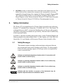
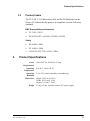
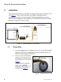
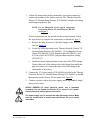
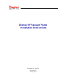
Dionex VP Vacuum Pump
Installation Instructions
Document No. 065186
Revision 02
January 2012
© 2012 Thermo Fisher Scientific Inc. All rights reserved.
Chromeleon is a registered trademark of Thermo Fisher Scientific Inc. in the United
States. PharMed is a registered trademark of Saint-Gobain Performance Plastics in the
United States and possibly other countries.
All other trademarks are the property of Thermo Fisher Scientific and its subsidiaries.
Thermo Fisher Scientific Inc. provides this document to its customers with a product
purchase to use in the product operation. This document is copyright protected and any
reproduction of the whole or any part of this document is strictly prohibited, except with
the written authorization of Thermo Fisher Scientific Inc.
The contents of this document are subject to change without notice. All technical
information in this document is for reference purposes only. System configurations and
specifications in this document supersede all previous information received by the
purchaser.
Thermo Fisher Scientific Inc. makes no representations that this document is complete,
accurate, or error-free and assumes no responsibility and will not be liable for any errors,
omissions, damage, or loss that might result from any use of this document, even if the
information in the document is followed properly.
Revision history: Revision 01 released May 2008
Revision 02 released January 2012
For Research Use Only. Not for use in diagnostic procedures.
Dionex VP
Installation Instructions
1.
Introduction
The Thermo Scientific Dionex™ VP Vacuum Pump (Dionex VP) (see Figure 1) is
a dual-stage diaphragm pump capable of providing a continuous vacuum. The
pump is designed for use with a wide range of IC (ion chromatography)
applications, consumables, and accessories.
Figure 1. Thermo Scientific Dionex VP Vacuum Pump and 15V Power Supply
There are two modes of pump operation:
•
•
In the manual control mode, the Dionex VP turns on and off when the user
presses a button on the rear panel.
In the relay control mode, the Dionex VP turns on and off in response to a
signal from the relay output of a controlling device (for example, a Thermo
Scientific Dionex ICS-3000 Detector/ Chromatography Module). Relay
control must be programmed in the Thermo Scientific Dionex Chromeleon®
Chromatography Data Management System.
When the pump is on, the VACUUM ON LED on the front panel is lighted.
Doc. 065186-02 1/12
1
Dionex VP Vacuum Pump Installation
2.
Description
Figure 2 illustrates the rear panel of the Dionex VP.
Figure 2. Dionex VP Rear Panel
•
RELAY
•
RELAY CNTRL ON/OFF selects
provides a connection to a relay output on the controlling device. The
input has a signal (+) pin and an active ground (-) pin.
the Dionex VP operating mode:
When the RELAY CNTRL button is pressed in (the ON position), the relay
control mode is selected.
When the RELAY CNTRL button is not pressed in (the OFF position), the
manual control mode is selected. When a relay cable is not connected to the
RELAY connector, use the RELAY CNTRL button to start and stop the pump.
2
•
DC IN
•
EXHAUST
provides a connection to the external 15V power supply (P/N 940068).
provides an outlet for venting evacuated air from the pump.
Doc. 065186-02 1/12
Safety Information
•
3.
provides a connection for the outlet line to the ballast reservoir. The
ballast reservoir line connects the vacuum to the consumable or accessory
required for the application (for example, the Thermo Scientific Dionex CRD
300 Carbonate Removal Device or the Thermo Scientific Dionex RFIC™
Eluent Degasser in the Thermo Scientific Dionex ICS-3000 Eluent Generator
or Thermo Scientific Dionex ICS-2000 Ion Chromatography System).
VACUUM
Safety Information
The Dionex VP was manufactured by Thermo Fisher Scientific at the following
location: 527 Lakeside Drive, Sunnyvale, CA 94088-3603 U.S.A. The Dionex VP
is designed for use with IC systems and should not be used for any other purpose.
Operation of the pump in a manner not specified by Thermo Fisher Scientific may
result in personal injury.
If you have a question regarding appropriate usage, contact Technical Support for
Dionex products before proceeding. In the U.S. and Canada, call 1-800-346-6390.
Outside the U.S. and Canada, call the nearest Thermo Fisher Scientific office.
3.1
Safety Messages
This manual contains warnings and precautionary statements that can
prevent personal injury and/or damage to the Dionex VP when properly
followed. Safety messages appear in bold type and are accompanied by
icons, as shown below.
Indicates an imminently hazardous situation which, if not avoided, will
result in death or serious injury.
Indicates a potentially hazardous situation which, if not avoided, may
result in death or serious injury.
Indicates a potentially hazardous situation which, if not avoided, may
result in minor or moderate injury.
Indicates that the function or process of the instrument may be
impaired. Operation does not constitute a hazard.
Doc. 065186-02 1/12
3
Dionex VP Vacuum Pump Installation
Messages d’avertissement en français
Signale une situation de danger immédiat qui, si elle n'est pas évitée,
entraînera des blessures graves à mortelles.
Signale une situation de danger potentiel qui, si elle n'est pas évitée,
pourrait entraîner des blessures graves à mortelles.
Signale une situation de danger potentiel qui, si elle n'est pas évitée,
pourrait entraîner des blessures mineures à modérées. Également
utilisé pour signaler une situation ou une pratique qui pourrait
gravement endommager l'instrument mais qui n'entraînera pas de
blessures.
Warnhinweise in Deutsch
Bedeutet unmittelbare Gefahr. Mißachtung kann zum Tod oder
schwerwiegenden Verletzungen führen.
Bedeutet eine mögliche Gefährdung. Mißachtung kann zum Tod oder
schwerwiegenden Verletzungen führen.
Bedeutet eine mögliche Gefährdung. Mißachtung kann zu kleineren
oder mittelschweren Verletzungen führen. Wird auch verwendet, wenn
eine Situation zu schweren Schäden am Gerät führen kann, jedoch
keine Verletzungsgefahr besteht.
Informational messages also appear throughout this manual. These are
labeled NOTE and are in bold type:
NOTE NOTES call attention to certain information. They
alert users to an unexpected result of an action,
suggest how to optimize instrument performance,
etc.
4
Doc. 065186-02 1/12
Product Specifications
3.2
Product Labels
The TUV GS, C, US Mark safety label and the CE Mark label on the
Dionex VP indicate that the pump is in compliance with the following
standards.
EMC Susceptibility and Immunity
•
UL 3101-1/10.93
•
EN 61326:1987+A1:1998+A2:2001+A3:2003
Safety
4.
•
EN 61010-1:2001
•
UL 61010-1:2004
•
CAN/CSA-C22.2 No. 61010-1:2004
Product Specifications
Power
Requirements
Operating
Temperature
Operating
Humidity
Dimensions
Weight
Doc. 065186-02 1/12
100 to 240 Vac, 50/60 Hz; 0.5 amp
4 to 40 ºC (40 to 104 ºF)
5% to 95% relative humidity, noncondensing
Height: 10.52 cm (4.14 in)
Width: 10.52 cm (4.14 in)
Depth: 18.12 cm (7.14 in)
2.0 kg (4.5 lbs); includes external 15V power supply
5
Dionex VP Vacuum Pump Installation
5.
Installation
This section describes how to complete the typical connections to the Dionex VP
(see Figure 3). These connections may vary slightly, depending on your
application; for details, refer to the manual for the consumable or accessory
required for the application. The manuals are included on the Thermo Scientific
Reference Library DVD (P/N 053891).
0.16-cm (0.062-in) ID
PTFE Tubing (P/N 014157)
0.32-cm (0.125-in) ID
PharMed Tubing (P/N 063267)
To controlling device
To consumable
Relay Cable
RELAY +ON
OFF
RELAY
CNTRL
DC IN
To power source
EXHAUST
VACUUM
Power Supply
(P/N 940068)
Ballast
Reservoir
Power
Cord
VP Rear Panel
Figure 3. Typical Dionex VP Connections
5.1
Pump Setup
1. Locate the ballast reservoir and the 0.32-cm (0.125-in) ID PharMed®
tubing (P/N 063267) provided in the Thermo Scientific Dionex VP
Vacuum Pump Package (P/N 066463).
2. Push one end of the PharMed
tubing onto the barbed fitting
on the ballast reservoir cap (see
Figure 4).
Connect the free end of the
tubing to the VACUUM
connector on the Dionex VP
rear panel (see Figure 2).
PharMed Tubing
(P/N 063267)
Inlet
Fittings
Figure 4. Ballast Reservoir Cap
6
Doc. 065186-02 1/12
Installation
3. Follow the instructions in the consumable or accessory manual to
connect the product to the ballast reservoir. The Thermo Scientific
Dionex VP Vacuum Pump Package (P/N 066463) includes the tubing
and fittings required for this.
NOTE For an illustration of the typical connections
between the Dionex VP and a Dionex CRD 300,
see Figure 7.
If these instructions are not included in the product manual, follow
the steps below to complete the connections as shown in Figure 3:
a. Remove the plug from one of the inlet fittings on the reservoir
cap (see Figure 4).
b. Locate the following items in the Thermo Scientific Dionex VP
Vacuum Pump Package (P/N 066463): 1/8-in flangeless ferrule
fitting (P/N 048949), 1/4-28 flangeless nut (P/N 048951), and
0.16-cm (0.062-in) ID PTFE (polytetrafluoroethylene) tubing
(P/N 014157).
c. Install the ferrule fitting and nut on one end of the PTFE tubing.
Connect this end of the tubing to the inlet fitting from which the
plug was removed. Connect the other end of the tubing to the
consumable or accessory.
4. Connect the 15V power supply (P/N 940068) provided in the Thermo
Scientific Dionex VP Vacuum Pump Package (P/N 066463) to the DC
IN connector on the Dionex VP rear panel (see Figure 2).
5. Connect a power cord to the power supply and to a grounded, singlephase power source.
SHOCK HAZARD—To avoid electrical shock, use a grounded
receptacle. Do not operate the Dionex VP or connect it to a power
source without an earthed ground connection.
The power supply cord is used as the main disconnect device. Make
sure the socket-outlet is located near the Dionex VP and is easily
accessible.
Doc. 065186-02 1/12
7
Dionex VP Vacuum Pump Installation
Operation at AC input levels outside of the specified operating voltage
range may damage the Dionex VP.
DANGER D'ÉLECTROCUTION—Pour éviter toute électrocution, il faut
utiliser une prise de courant avec prise de terre. Ne l'utilisez pas et ne
le branchez pas au secteur C.A. sans utiliser de branchement mis à la
terre.
Le cordon d'alimentation principal est utilisé comme dispositif
principal de débranchement. Veillez à ce que la prise de base soit
située/installée près du module et facilement accessible.
STROMSCHLAGGEFAHR—Zur
Vermeidung
von
elektrischen
Schlägen ist eine geerdete Steckdose zu verwenden. Das Gerät darf
nicht ohne Erdung betrieben bzw. an Wechselstrom angeschlossen
werden.
Das Netzkabel ist das wichtigste Mittel zur Stromunterbrechung.
Stellen Sie sicher, daß sich die Steckdose nahe am Gerät befindet und
leicht zugänglich ist.
6. If you plan to operate the Dionex VP in the manual control mode (see
page 1), check the following:
a. Make sure the RELAY CNTRL button is in the OFF position (the
button is not pressed in).
b. Make sure the chromatography pump is on.
Never turn on the Dionex VP unless the chromatography pump is
already on. To prevent damage to the consumable or accessory,
eluent flow must be established before a vacuum is applied.
c. Press the RELAY CNTRL button to turn on the Dionex VP. The
Dionex VP is now ready for operation in the manual control
mode.
8
Doc. 065186-02 1/12
Installation
7. If you plan to operate the Dionex VP in the relay control mode (see
page 1), check that the RELAY CNTRL button is in the ON position (the
button is pressed in). Then, complete these additional steps:
a. Locate the relay connector (P/N 923617) and twisted wire
assembly (P/N 043598) in the Thermo Scientific Dionex VP
Vacuum Pump Package (P/N 066463).
b. Insert the ends of the wires into the plug. (If necessary, strip the
ends of the wires first.)
c. Connect a red signal wire to the + pin on the Dionex VP. Connect
a black ground wire to the - pin.
d. Connect the other ends of the signal wires to the corresponding
relay output signal and ground pins on the controlling device. For
instructions on how to connect the Dionex VP to a Dionex ICS3000 DP/SP, go to page 9. For instructions on how to connect the
Dionex VP to a Dionex ICS-1000/1500/2000, go to page 10.
Connecting the Dionex VP to a Dionex ICS-3000 DP/SP
1. Locate the 25-position
connector plug
(P/N 923968) in the
Dionex ICS-3000
DP/SP Ship Kit.
Remove the cover of
the plug (see Figure 5).
Position 8
Position 14
Position 20
Position 15
Figure 5. 25-Position Connector Plug (Cover removed)
Doc. 065186-02 1/12
9
Dionex VP Vacuum Pump Installation
2. Connect the Dionex VP connector plug to the 25-position connector
plug. Refer to the table below for pin connections.
To attach a wire to the 25-position connector plug, insert it into the
plug, and use a screwdriver to tighten the locking screw. Repeat for
the second position.
When attaching wires to the connector plug, be careful not to allow
stray strands of wire to short to the adjoining position on the
connector.
Connections for One Dionex VP to a Dionex DP/SP
Connect this Dionex VP
pin:
To this position on the connector plug:
Pin 1
Position 20
Pin 2
Position 8
Connections for a Second Dionex VP to a Dionex DP
Connect this Dionex VP
pin:
To this position on the connector plug:
Pin 1
Position 14
Pin 2
Position 15
3. Replace the cover on the 25-position connector plug. Plug the
connector into the digital I/O port on the Dionex DP/SP rear panel.
Go on to Section 5.2 to set up Chromeleon.
Connecting the Dionex VP to a Dionex ICS-1000/1500/2000
1. Locate the 12-position
connector plug
(P/N 923686) in the
Dionex ICS-1000/1500/
2000 Ship Kit (see
Figure 6).
Position 1
Locking
Screws
Position 12
Figure 6. 12-Position Connector Plug
10
Doc. 065186-02 1/12
Installation
2. Connect the Dionex VP connector plug to the 12-position connector
plug. Refer to the table below for pin connections.
To attach a wire to the 12-position connector plug, insert it into the
plug, and use a screwdriver to tighten the locking screws.
When attaching wires to the connector plug, be careful not to allow
stray strands of wire to short to the adjoining position on the
connector.
Connect this Dionex VP
pin:
To this position on the connector plug:
Pin 1
Position 3
Pin 2
Position 4
3. Plug the 12-position connector plug into the TTL and relay connector
on the Dionex ICS-1000/1500/2000 rear panel.
Go on to Section 5.2 to set up Chromeleon.
Doc. 065186-02 1/12
11
Dionex VP Vacuum Pump Installation
5.2
Chromeleon Setup
This section briefly explains how to perform two tasks:
•
Select a relay output for remote on/off control of the Dionex VP
•
Program relay control of the Dionex VP in Chromeleon
If you need detailed instructions, refer to the Chromeleon user’s guide or
Help.
1. If it is not already running, start the Chromeleon Server Monitor.
(Select Start > All Programs (or Programs, depending on the
operating system) > Chromeleon > Server Monitor.)
The Server Monitor window opens.
2. The Server Monitor status message should be “Chromeleon Server is
running idle.”
3. Open the Chromeleon Server Configuration program. (Select Start >
All Programs (or Programs, depending on the operating system) >
Chromeleon > Server Configuration.)
4. Click the + sign next to the timebase that includes the controlling
device for the Dionex VP.
5. Right-click the icon for the controlling device.
The Properties dialog box for the device appears.
12
Doc. 065186-02 1/12
Installation
6. Go to the tab page where relay properties are defined (the page name
varies, depending on the device). For example, the TTLs/Relays/AC
tab page for the Dionex ICS-3000 DC is shown here.
7. Select the check box next to the relay output that will be used to
control the Dionex VP.
Doc. 065186-02 1/12
13
Dionex VP Vacuum Pump Installation
For a Dionex ICS-3000 DP/SP:
a. Highlight relay 2 or 4 on the TTLs/Relays/AC tab page. If the
pump is a Dionex DP, assign relay 2 to the top pump and relay 4
to the bottom pump in the module.
b. Press the F2 key to display the Device Configuration dialog box.
c. In the drop-down box, select Flow Zero as the Function for the
selected relay. This ensures that the Dionex VP is automatically
turned off whenever the chromatography pump is turned off or
the flow rate is set to zero.
If the Dionex VP continues to draw a vacuum when the
chromatography pump is not pumping liquid, the consumable or
accessory may be damaged. For example, the vacuum may destroy
the membrane inside the Dionex CRD.
NOTE The Flow Zero function is not available unless
Dionex DP/SP Moduleware version 2.75 (or
later) is installed.
d. Click OK.
14
Doc. 065186-02 1/12
Installation
For a Dionex ICS-1000/1500/2000 pump:
a. Highlight relay 2 on the State Devices tab page.
b. Press the F2 key to display the Device Configuration dialog box.
c. Select Flow Zero as the Function for relay 2. This ensures that
the Dionex VP is automatically turned off whenever the
chromatography pump is turned off or the flow rate is set to zero.
If the Dionex VP continues to draw a vacuum when the
chromatography pump is not pumping liquid, the consumable or
accessory may be damaged. For example, the vacuum may destroy
the membrane inside the Dionex CRD.
NOTE The Flow Zero function is not available unless
Dionex
ICS-1000/1500/2000
Moduleware
version 3.0.0 (or later) is installed.
d. Click OK.
8. Click OK to close the Properties dialog box.
9. If it is not already running, start the Chromeleon client. (Select Start
> All Programs (or Programs, depending on the operating system) >
Chromeleon > Chromeleon.)
10. In the Program Wizard, specify when to start and stop the relay
selected in Step 7.
For example, the Relay and State Devices Options tab page for the
Dionex ICS-3000 DC is shown here.
Doc. 065186-02 1/12
15
Dionex VP Vacuum Pump Installation
11. When you finish editing the program, click Finish on the final page
of the wizard to save the changes.
The Dionex VP is now ready for operation in the relay control mode.
16
Doc. 065186-02 1/12
Troubleshooting
6.
Troubleshooting
If you are unable to eliminate a problem by following the instructions here,
contact Technical Support for Dionex products before proceeding. In the U.S. and
Canada, call 1-800-346-6390. Outside the U.S. and Canada, call the nearest
Thermo Fisher Scientific office.
•
Dionex VP fails to respond to relay commands
If the Dionex VP fails to turn on or off when the corresponding command is
executed, check the following:
a. Verify that the RELAY CNTRL button on the Dionex VP rear panel is in the
OFF position (the button is not pressed in).
b. Verify that the appropriate relay output was assigned to control the pump
in the Server Configuration program (see Section 5.2, Step 7).
•
Dionex VP continuously emits a high-pitched noise
A liquid leak in the plumbing will allow air to flow into the Dionex VP,
prevent the pump from achieving a steady-state vacuum level, and produce a
high-pitched noise during operation.
a. Check all liquid line connections for leaks. Tighten fittings, or replace
tubing and fittings as required.
b. Tighten the ballast reservoir cap.
Doc. 065186-02 1/12
17
Dionex VP Vacuum Pump Installation
A.
Connections from the Dionex VP to the Dionex CRD
300
The Dionex CRD 300 Carbonate Removal Device consists of a gas-permeable
membrane with a silicone coating that is selective to CO2. When the Dionex CRD
300 is running in the vacuum regeneration mode, the Dionex VP evacuates CO2
from the regenerant channel that encloses the membrane. A bleed line helps
remove gaseous carbon dioxide by bleeding a small amount of air into the
regenerant channel.
Figure 7 shows the typical tubing connections for the vacuum regeneration mode.
NOTE Figure 7 is provided for reference only; refer to the
Dionex CRD 300 manual for current product
information. The manual is included on the Thermo
Scientific Reference Library DVD (P/N 053891).
0.16-cm (0.062-in) ID
Teflon Tubing (P/N 014157)
0.32-cm (0.125-in) ID
PharMed Tubing (P/N 063267)
To controlling device
Bleed Line
Relay Cable
Regen Out
CRD 300
ELUENT
OUT
RELAY +ON
OFF
RELAY
CNTRL
CRD 300
ELUENT
IN
Suppressor
ELUENT OUT
Regen In
CRD 300
DC IN
EXHAUST
Ballast
Reservoir
Conductivity
Cell
CELL IN
VACUUM
CELL OUT
VP Rear Panel
Figure 7. Example Flow Schematic: Dionex CRD 300 Vacuum Regeneration Mode
18
Doc. 065186-02 1/12