1
.c
om
SIEMENS
Instruction
Installation
Operation
Maintenance
ua
ls
SCOR Overcurrent
Protective Relay
Function Data
ar
TIJ
.ap
F D
tM
an
Hardware 3.11
Software 3.40
I
AB C
A
1-lll-1
Ll. -1 =I
H
lP
B
C
G
.E
lec
tri
ca
E
1
I
ww
w
,,
Manual No. SG-9228-01
'
Time
'
.
'
,,
:
'
" ,t'\
lnst. 1
•• •
A
B
c
G
.c
om
ua
ls
an
tM
ar
lP
ca
tri
lec
,,
t
'
ww
. .,
•
'
'
..
fill '
fill
1r II
•
..
•
•
w
.E
, .. ..
g
•
•
I
..
..
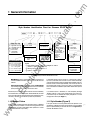
M edium voltage switchgear withAccessTM system field devices
•
SCOR overcurrent orotective relav
c
I,
.i
.c
om
1 General Information
Page 1
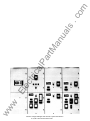
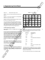
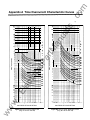
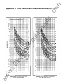
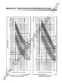
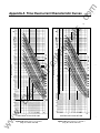
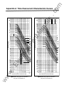
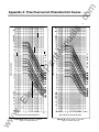
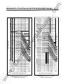
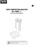
Selection of the timing characteristics is made at the front panel
or via one of the two communications links. After a characteristic
is selected , it is adjusted to specific requirements by choosing
the TIME DIAL number. (These are the numbers in a vertical row
along the right hand margin of Figures A.1 through A.16.) This
TIME DIAL number (Oto 99) selects oneofthe 1 OOcharacteristic
curves available for each characteristic. (Only 1 4 of the 1 00
curves in the relay's memory are shown on each graph because
of space limitations.)
tM
The relay provides for the incorporation of an optional plug-in
communications board to interface with the Siemens Power
Monitor™ display and monitoring unit. The communications
interface, when fully implemented, allows remote monitoring of
real-time system and circuit breaker information and the trans
mission of event and historical data, as well as remote configu
ration of operating parameters.
ua
ls
The Siemens Communicating Overcurrent Relay (SCOR) is a
microprocessor-based , time overcurrent relay designed for easy
incorporation into a computer-monitored power system . It is
available in a number of styles to supply single-phase, two
phase-with-ground, three-phase, and three-phase-with-ground
protection for 60 Hz power systems.
One of 1 6 families of time overcurrent characteristics may be
selected for the monitored phases. These families are graphi
cally illustrated in Figures A.1 through A.1 6 in Appendix A.
If ground current is monitored, its timing characteristic is
independently selected from the 16 families.
an
1.1 Description
ar
1.2 Application
The selected TIME DIAL number is entered into the relay's
memory, again using either the frontpanel data entry controls,
or one of the two communications links. The available charac
teristic curves include one definite time, six inverse time, and
nine IZT curves. (Refer to Table 4.)
lP
The SCOR relay is utility grade and is provided in a draw-out case
with built -in test facilities. It is used for the protection of medium
voltage electrical power systems. It is designed to monitor the
outputs of standard (5 A secondary) current transformers and,
when it operates, to close an output contact that may be used
to trip a circuit breaker.
ca
The relay requires control power for its internal circuits. A number
of ac and de voltage options are available for this purpose that
match the usual ac or de control power used for tripping the
circuit breaker.
.E
lec
1 .3.1 Pickup
tri
1.3 The Time Overcurrent Function
A coarse incremental selection of overcurrent pickup tap is
provided by front panel rotary switches. One switch simulta
neously sets the pickup tap for all the monitored phases. If ground
is also monitored, a second rotary switch independently sets the
ground overcurrent pickup tap.
A fine incremental adjustment that provides 99 intermediate
pickup points between adjacent positions of the rotary switches
is provided by entering data into the memory of the internal
microcomputer tap calibration registers.
w
1 .3.2 Timing
ww
A time delay is initiated when a pickup point is exceeded. When
the current drops below pickup, the timing circuit is reset
immediately. The amount of delay required before trip is a
function of the overcurrent magnitude.
1 .3.3 Trip and Reset
When the monitored current exceeds the overcurrent pickup
point, the TMG LED illuminates as timing begins. The timing
process continues until the interval calculated by the selected
time overcurrent characteristic is completed (thereby tripping
the associated output contact and target indicators}, or until the
sensed overcurrent drops below the pickup setting (which
causes the timer to reset). In either case (trip or reset), the timing
process is terminated. The TMG LED extinguishes at reset, but
remains on at trip as an indication of contact closure.
If a relay output is closed, it is immediately reset when the
monitored current drops below the pickup setting. Targets,
however, remain tripped until manually reset at the front panel.
(Control power is required to reset the targets.)
1.4 RMS Sensing
·:ff
The SCOR protective relay uses RMS Sensing, a technology first
introduced by Siemens in 1 985, to sample the current wave
shape and quickly calculate the effective heating value of the
current. SCOR relays evaluate the impact of harmonics and
provide accurate circuit protection. The SCOR relay uses a sum
of squares algorithm for both determining trip level and for
calculating metered values of the relay current level. The input
waveform is sampled several times to determine instantaneous
values. These instananeous values are processed to obtain the
true RMS value of the input current.
.c
om
1 General Information
2
tM
an
ua
ls
Page
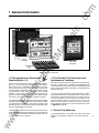
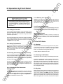
Shown with
Front Cover
Assembled
lP
ar
Cradle
Assembly
ca
Figure 1 . Relay Construction
1 .5 The Instantaneous Overcurrent
1 .6 The Ground Time Overcurrent and
Function(Option 1 -1 )
Instantaneous Functions
.E
lec
tri
One or two instantaneous overcurrent outputs are available,
Options 1-1 and 1 -2. Normally one is selected. The instanta
neous pickup point is adjustable from 0.50 times to 20 times
the time overcurrent pickup point. When the sensed input
current exceeds an instantaneous overcurrent pickup setting,
an instantaneous output relay is energized. Also a target
indicator is set to show that an instantaneous output was
tripped. (On multi-phase relays, an additional indicator denotes
the phase or ground element which initiated the tripping.)
If an instantaneous option is selected for a relay which includes
both phase and ground sensing, then an instantaneous output
is supplied which operates for both phase protection and
ground protection. The instantaneous phase and ground pickup
points are independent of each other.
ww
w
The desired instantaneous overcurrent pickup values for phase
and for ground are entered via the data entry controls at the front
panel. (This can also be done remotely by the data link if the
communications option is present.)
When the sensing input type includes ground current sensing,
the relay is supplied with a separate and independent time
overcurrent function for ground, as previously described for the
phases. When instantaneous is selected, it is supplied for both
phase and ground.
The signal for the ground function can be obtained by connect
ing the ground element in the residual circuit of three current
transformers connected in the phases (51 Nor SON /51 N), from
a current transformer in series with the connection from the
power transformer neutral to ground (51 G). or from a core
balance current transformer encircling all phase conductors,
often called a zero sequence CT (51 GSor SOGS/51 GS). Refer
to Figures 8 through 1 2.
1 . 7 Ground Trip Selectivity
This standard feature of the SCOR relay allows the ground
element to be enabled or disabled on the timed and INST 1
output.
.c
om
1 General Information
Page 3
1 .8 Auxiliary Output Relay (Option 1 -2)
ca
lP
INST 2. This provides a second instantaneous trip contact,
which can be set independently of INST 1 , and the contact
can be used in a different circuit. This is for application in
reclosing schemes to block reclosing for high magnitude
faults. It can also be used to block tripping of an interrupting
device above its interrupting rating.
COMMAND ACTUATED CLOSE. This selection is only
available if the SCOR relay is equipped with a communica
tions card (Option 2-C). This is used to permit remote
closing of the circuit breaker. A remote close signal may be
transmitted over the communications link to initiate closure
of this output relay if the breaker is open. The relay contact
must be wired into the circuit -breaker close circuit in this
application.
Separate GROUND TRIP. It is necessary in some applica
tions to trip a separate lockout relay for ground faults. This
can be achieved by selecting Option 1 -2, and configuring
the relay to cause tripping through this separate relay
contact for ground faults. The ground tripping can be for
operation of both the time and instantaneous elements, but
either can be configured to be disabled if desired.
ww
w
c.
.E
lec
tri
b.
�
�
�
,l�
C/�
r
��'
nterface (a plug-in board, Option 2-C)
The communi:�::
supports an R
�rt on the front panel and an RS-485 po
on the back of ttie relay's case. (These are also known by the
designations EIA-232 and EIA-485.) Both ports have equal
access to the relay's registers. When connection is made to the
RS-232 port, the RS-485 port is disabled .
0
The RS-232 port is for relatively short range communication
(under 50 feet). Its intended purposes are for initial configuration,
local testing and maintenance when the relay is not connected
to a Power Monitor unit.
The RS-485 port provides for intercommunication between the
relay and a Siemens Power Monitor unit or a computer running
the Power Monitor PC software. Communication is provided
over a shielded twisted pair cable at distances of up to 4000 feet.
The Power Monitor unit permits convenient remote configura
tion, maintenance and monitoring.
ar
This option includes an additional target identified as "INST 2/
CLOSE". The option can be used in any one of three ways:
a.
1 .9.1 The Ports
7
;0
0
tM
Alternatively, ground trip functions can be shifted to the auxiliary
output relay if this option is installed. This option is configured at
Display Sequence 20 of the Configuration Menu (see Page 1 1 ).
ua
ls
For some applications, the ground element may be present, but
not desired. It may be disabled completely at Display Sequence
20 of the Configuration Menu (see Page 1 1 ).
1 .9 Communications Option
an
Some applications require that the instantaneous element be
active for phase, but not for ground, and vice versa. Other
applications may require instantaneous tripping with no time
overcurrent function. When the time or instantaneous function
is not desired, this may be achieved by disabling either when
configuring the relay at Display Sequence 20 of the Configura
tion Menu (see Page 1 1 ).
1 .9.2 Communications
The data and configuration capability ofthe communications link
includes:
Real-time data for amperes (each phase and ground),
and amperes demand (each phase). The monitored current
is expressed in primary kilo amperes:
/monrtored
= /,elay (CT ratio)
Relay status (normal/timing/tripped), and breaker posi
tion (open/closed).
'
�
Event record, with amperes prior to trip, time stamp,
element which caused trip, and fault accumulation.
Trip log, including status changes, RMS current, and time
stamp. The last 20 events are stored in the relay's nonvola
tile memory. -------
.c
om
1 General Information
ua
ls
Page 4
Style Number Identification Chart for Siemens SCOR Relay
I D D [§]
SCOR
-
� [i] D - � D D D �
Power Supply
=
Single-Phase Current
G
=
Three-Phase Current
H
=
X
=
®
®
E
=
K
N.O. Contacts
J
TARGET
3
4
NOTES:
2.0 - 11 A for all phases
0.5 - 5.0 A for ground
CD
0.5 - 5.0 A for all phases
2.0 - 11 A for ground
=
0.5 - 5.0 A for all inputs
=
2.0 - 11 A for all inputs
ar
B
Switch Selectable
8 and C Timing
Curves
®
@
=
Function targets are
current operated;
element tergets are
internally operated.
=
1
=
2
=
None
CD
Elements CD
One lnst. Element
Two lnst.
OR
One Ins!. Element
and one ExternalProgram-Controlled
Contact
OR
Separate
Ground Trip
Contact
Each element includes a relay which energizes for either a
phase or a ground instantaneous trip.
Sensing input range must be 3 or 4.
ca
=
=
0
lP
SENSING INPUT TAP RANGE
2
Vdc
Two-Phase-with
Ground Current
Z5
=
48
125 Vdc/120 Vac
Three-Phase-withGround Current
TIMING
1
=
=
tM
K
an
I
0
=
1
=
S
=
N
=
C
=
None
Power Supply
Hold-up Circuit
®
Semi-Flush
Mounting
Option 2
Option 2 must be C.
None
Communications
Board Installed
tri
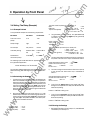
Figure 2 Style Number Identification Chart
MIN/MAX log, which contains the minimum and maximum
current and demand values which have occurred since last
cleared.
Whichever port is used, all communications must be initiated by
the Power Monitor unit or computer. When addressed, all of the
relay's storage registers may be read by the Power Monitor unit,
and many of them can be altered. (Password protected .)
If a breaker failure is detected, a time-stamped message
"Breaker Failure" is sent to the Power Monitor unit Event Log.
This feature may be disabled at Display Sequence 21 of the
Configuration Menu (see Page 1 1).
1.10 Breaker Failure
1.11 Style Number (Figure 2)
When the relay includes the Communications Option, a "Breaker
Failuare" feature is provided. This functions to signal if the circuit
breaker does not open immediately after operation of a time
and/or instantaneous output relay.
The style number of the relay determines the features to be
included (or ordered) for a particular application. Each available
option is represented by a character as shown in Figure 2 Style
Number Identification Chart.
ww
w
.E
lec
Configuration data for all registers listed in Table 3 (Page
1 1 ), including time overcurrent function and curve selected,
pickup settings, and current transformer ratios.
The breaker failure function involves a 1 -second timer. When a
trip occurs, the timer starts. At time-out, two checks are made;
one, that the breaker properly changed state (opened), and two,
that the current is below approximately 1 0% of the tap value. If
the result of either check is not correct, then it is assumed that
the circuit breaker has failed to open and/or failed to interrupt the
current.
.c
om
1 General Information
Page 5
For example, if it is decided that three-phase-with-ground
monitoring is required for an application, then the first character
of the style number is H .
ua
ls
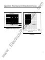
1 . 1 3 Instantaneous Overcurrent
CharacteristicCurves
The characteristic curves for the instantaneous relay functions
are also presented in Appendix A. Figure A.1 7 shows the
curve for the Phase Instantaneous function, and Figure A.18
shows the curve for the Ground Instantaneous function .
The second character of the style number determines the range
for overcurrent pickup. For example, Sensing Input Tap Range
1 would provide a range of 2.0 to 1 1 .0 A for each phase, and
a range of 0.5 to 5.0 A for ground current. Normally open (NO)
output contacts for tripping the breaker are standard , so output
Option E is the third character. The fourth and fifth characters are
Timing Option Z5, which is standard on the SCOR relay. This
feature allows the timing to be selected from any of the sixteen
overcurrent timing functions illustrated in Figures A.1 through
A.1 6. The sixth character represents the voltage of the source
of operating power for the relay. If J, the internal power for the
relay is derived from an external source of (a nominal) 1 25 Vdc
or 1 20 Vac.
an
Table 1 . Available Characteristics
Time Overcurrent
Cha racteristic
Figure
b1
Short Inverse Time
A.1
b2
Long Inverse Time
A.2
b3
Definite Time
A.3
b4
Moderately Inverse Time
A.4
b5
Inverse Time
A.5
b6
Very Inverse Time
A.6
b7
Extremely Inverse Time
A.7
b8
12T
A.S
c1
12T with limit 1
A.9
c2
12T with limit 2
A.10
c3
12T with limit 3
A.11
c4
I2T with limit 4
A.12
c5
12T with limit 5
A.13
c6
12T with limit 6
A.14
c7
12T with limit 7
A.15
cs
12T with limit 8
A.16
tM
Number
...
lP
ar
Since only one target configuration is offered, the seventh
character is B. Note that all of the FUNCTION targets are current
operated . Current operated targets are advantageous because
they confirm that a current flowed in the output circuit as the
result of a trip. (Since the ELEMENT targets are not associated
with any output contacts, they are internally operated.)
ca
If one instantaneous overcurrent element is needed, the eighth
character of the style number is 1 . If any one ofthe three features
provided by Option 1 -2 is desired , the eighth character of the
style number is 2 . The ninth character must be C to specify the
communications board option. This wou ld allow communica
tion with a Power Monitor unit or a local terminal.
.E
lec
tri
The tenth character of the style number is 0 if the control power
for the power supply is DC. However, if 1 20 volt AC control
power is to be used, then this character must be 1. The last
character is always S. (These relays are always supplied in a
draw-out case for semi-flush mounting .)
1.12 Time Overcurrent Characteristic
Curves
ww
w
Table 1 lists the types ofTime Overcurrent Characteristic Curves
available and the Number entered into the appropriate register
during configuration. The curves are presented in Figure A.1
through A.1 6 in Appendix A.
....
.c
om
2 Controls and Indicators
Page 6
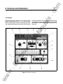
Figure 3 shows the front panel of the SCOR relay with all the
ua
ls
2.1 General
in primary kilo amperes. The Time Target and Element B Target
options installed except Option 1-2. All of the front panel
are shaded darker, indicatingthatthe relay caused an overcurrent
letter. Table 2 supplies a description for each. Data is displayed
been reset.
timed trip due to a fault on Phase B, and the targets have not
E
F
G
H
ar
tM
D
an
controls and indicators are called out and assigned a locator
lP
J
K
ca
c
ww
w
tri
.E
lec
Q
L
p
0
Figure 3. Controls and Indicators
N
Page 7
ua
ls
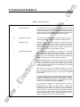
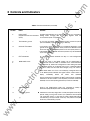
Table 2. Controls and Indicators
Locator
.c
om
2 Controls and Indicators
Function
A
PHASE TAP selector
A ten-position switch that provides an incremental adjustmen t of the
current pickup tap for all of the phases (simultaneously). The switch
positions are defined for both HIGH and LOW range in a table printed on
the front panel ( locator 0 of Figure 3). (Intermediate settings between the
switch positions may be established by the Tap Cal register.)
B
Timing indicators, phase
LEOs that illuminate when the preset overcurrent pickup point for the
corresponding phase is exceeded, to indicate that timing is underway.
c
Range plate, phase
Indicates the current tap range that applies to the internal scaling of all
the phase inputs of the relay. The range is either HIGH or LOW.
(Reference the TAP value table, locator 0.) Note that the range is
determined (during manufacture) by the style number of the relay. The
position of this plate serves only a documentary purpose.
0
FUNCTION/OATA display?
ar
tM
an
Name
lP
This four-character, seven-segment LED display (with a right-hand
decimal point for each digit) has two modes of operation: (1 ) the DATA
mode which permits reading the information registers in primary kilo
amperes, and (2) the CONFiguration mode that permits reading and
writing into those registers that control operation of the relay.
ww
w
.E
lec
tri
ca
The instrumentation registers monitor the input current and the demand
current in kilo amperes. A row of dashes indicates an out-of-range
condition. (Dashes along the bottom of the display indicate that the
current is somewhere below 1 0% of TAP; dashes along the top indicate
a current above 1 50% of TAP.)
When the relay is powered up, the display will default to the DATA
mode. Crossing from one mode to the other, and entering/modifying thE
data is described briefly below (locators I, J}, and in detail in Operation
by Front Panel.
When the d isplay exhibits the word "dAtA" for 60 seconds, the display
wil l begin scrolling through the instrumentation registers in a fixed
sequence. After stepping through all of the DATA registers, the display
wraps aroun d to repeat the sequence until instructed otherwise. This
process is covered in detail beginning on Page 1 0.
A front-panel switch (locator I) can cause the display to exhibit a
particular register of interest in either mode. If, while in the
CONFiguration mode, neither the UP/OWN nor the MODE/NEXT
switches have been actuated for one minute, the display will revert to
the DATA mode. (This protects the settings by requiring the deliberate
action of loading to effect a change. In the DATA mode, however, a
specifically selected register can be displayed indefinitely.) Note that
when in the CONFiguration mode, the relay is inoperative.
.c
om
2 Controls and Indicators
Page S
Locator
Name
ua
ls
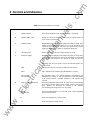
Table 2. Controls and Indicators (continued)
Function
Provides interconnection for any RS-232 device that is to be used for
RS232 PORT
(Supplied with the communications reading and/or changing data in the relay registers when the
option)
communication option is supplied.
F
TMG indicator, ground
An LED that illuminates when the preset ground overcurrent pickup
point is exceeded , to indicate that timing is underway.
G
GROUND TAP selector
A ten-position switch that provides an incremental adjustment of the
ground current pickup point. The switch positions are defined for both
HIGH and LOW range in a table printed on the front panel (locator 0).
(Intermediate settings between the switch positions may be established
by the Tap Cal register.)
H
STATUS indicator
tM
ar
An LED that illuminates whenever the relay is in the CONFiguration
mode
lP
Holding this switch in the MODE position (up) for approximately 5
seconds when the word "dAtA" is exhibited on the FUNCTION/DATA
display (locator D), selects the CONFiguration mode. Holding the switch
in the MODE position for 5 seconds when "ConF" is displayed selects
the DATA mode, and also loads data changes (if any) into memory.
ca
MODE/NEXT switch
an
E
UP/DOWN switch
.E
J
lec
tri
When neither "dAtA" nor "ConF" is on the display, holding the switch up
in the MODE position identifies the register whose contents were on
display
immediately
before
the
switch
was
operated.
ww
w
K
Tap range, ground
Each time the switch is toggled to the NEXT position (down), the display
advances to the next function in the sequence (if the DATA mode was
selected) or to the next operating parameter (if CONF was selected).
Active in the CONFiguration mode only: Increments (if raised) or
decrements (if depressed) the value of the displayed register.
Indicates the current tap range (HIGH or LOW) that applies to the relay's
internal scaling of the ground current input. (Reference the frontpanel
TAP value table, locator 0.) Note that the range is determined (during
manufacture) by the style number of the relay. The position of this plate
serves only a documentary purpose.
.c
om
2 Controls and Indicators
Locator
Controls and Indicators (continued)
ua
ls
Table 2.
Page 9
Function
L
POWER indicator
Red LED that illuminates when relay power supply is functioning.
M
TARGET RESET switch
Raising this switch simultaneously resets all of the targets (locators N
an
Name
and P) if relay is powered up.
N
ELEMENT targets
Magnetically latched indicators that change from black to orange when
tripping occurs to indicate the phase (A, B, or C) or ground (N) that
tM
caused the trip. Depending on the relay's style number, some of these
targets may not be present. Reset by Target Reset Switch (M).
TAP scaling chart
p
FUNCTION targets
Defines the settings of the TAP switches (locators A and G)
ar
0
Magnetically latched indicators that change from black to orange when
a relay output has tripped. Note that the current through the associated
lP
output contact must exceed 0.2 A to actuate the target. For reset see
M.
Depending upon the style number, some of the illustrated targets may
not be present.
TIME
INST 1
ca
Indicates that a trip was caused by a TIME overcurrent function.
tri
INST 2/CLOSE
PUSH TO ENERGIZEOUTPUT
ww
w
.E
Q
lec
(not illustrated)
INST 1 1ndicates a trip initiated by the INSTantaneous-1 function.
Only provided if Option 1-2 is selected. Indicates a trip initiated by the
INSTantaneous-2 function or, that a CLOSE contact output was initiated
by an external computer- controlled command, or that a ground trip
occurred.
Momentary pushbuttons that provide the means to test the functioning
of the output contacts without having to apply current to the sensing
inputs.
Buttons are depressed by inserting a
non-conducting rod through holes in the front panel.
1 /8"
diameter
12/CLS
Closes the INSTantaneous-2 or the CLOSE output contact (depending
(not illustrated)
upon the option present).
11
Closes the lnstantaneous-1 output contact.
n
Closes the Timed Trip output contact.
.c
om
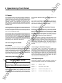
3 Operation by Front Panel
Page 10
3.1 General
ua
ls
Upon release of the MODE switch, the STATUS LED will be lit,
and "ConF" will be in view on the FUNCTION/DATA display.
(Releasing the MODE switch before 5 seconds has expired
returns the unit and display to the DATA mode.)
3.2.3 Stepping Through the Read/Write Registers
Starting with the display reading "ConF," you may step through
the configuration registers by depressing and releasing the NEXT
switch. The registers will appear in the sequence given in Table
3. Alternately, the register abbreviation will be displayed , followed
by the value or choice for that register. If you stop, the value is
displayed . lf you forget what register is being displayed , lift up on
the switch again to display the register abbreviation.
tM
The memory registers accessible from the front panel fall into two
basic categories: read-only registers which are accessible when
the relay is in the DATA mode (the normal or working mode), and
the read/write registers which may be accessed only when the
relay is in the CONFiguration mode.
becomes blank. Release the switch after "ConF" appears in the
display.
an
Once installed , and with its operating parameters established in
internal memory, the relay functions automatically to protect the
system from overcurrent conditions. Front panel operation of the
relay permits configuring the registers that define the relay's
automatic operation. These parameters are entered into the
relay's memory by using the controls and indicators that were
introduced in the Controls and Indicators section, and are further
explained below.
After the 22nd register is reached, one more depression of the
NEXT switch brings the display back (full circle) to the "ConF"
position. At this point, you have the option of stepping through the
configuration registers again, or returning to the DATA mode. To
effect the latter, raise the MODE switch up and hold it there until
the word "dAtA" appears in the display. (This requires about 5
seconds.)
3.2 The Configuration Mode
ca
3.2. 1 Defined
lP
ar
Note that all the registers accessible at the front panel (plus many
others that aren't) are also accessible by remote computer and
by local terminal. For more information on controlling the SCOR
relay from a remote computer, see Section 8.8 in Appendix B.
For information about control! ing the SCOR relay from a Siemens
Power Monitor unit, see the Siemens Power Monitor™ Display
and Monitoring Unit, (Manual No. SG-401 8-01 ).
lec
tri
Configuring the relay means loading the operating parameters
into the relay's internal registers and setting the PHASE TAP and
GROUND TAP switches. The CONFiguration registers are ac
cessible (and alterable) whenever the relay is in the configuration
mode, i.e., when the letters "ConF" appear in the front-panel
display and the STATUS LED is illuminated . (These registers may
also be read or altered remotely by computer.)
3.2.2 Entering the Configuration Mode
.E
IMPORTANT NOTE
It is recommended that the Circuit Breaker be in the open
position while the SCOR relay is being configured from the
front panel. The SCOR relay is inoperative in the CONFiguration
mode.
ww
w
To leave the DATA mode and enter the CONFiguration mode,
depress the MODE/NEXT switch repeatedly until the word
"dAtA" is in view on the front-panel display. Then hold the switch
up for approximately five seconds, during which time the display
3.2.4 Loading the Read/Write Registers
As the MODE switch is held raised (in the procedure just
described for returning to the DATA mode). the display should
become blank, and then , after about 5 seconds, the message " P
EE" should appear. This indicates that the data changes made
while in the CONFiguration mode have now replaced the former
contents of the registers in the nonvolatile memory. After a brief
interval, the display changes again to read "dAtA." The relay is
now returned to its normal operating mode.
3.2.5 Programming Note
SCOR relays supplied on Siemens switchgear products are
normally configured at the factory with the following settings:
Register
Address . . .Addr
Register 2
Baud Rate . . . bAud . . .4800
Register 1 3
Phase CT Primary Amps . . . PPri
Register 1 5
Ground CT Secondary Amps . . . nPri
Page
Register
Display
Abbreviation
5
6
7
8
9
10
11
12
14
15
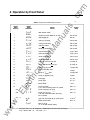
Phase Jime qial setting
0000 to 0099
Grou.Qd Jime qial setting
0000 to 0099
Phase tAP calibrate
0000 to 0099
Ground tAP calibrate
17
.E
lec
18
19
20
20A
208
20C
w
21
22
*
50 9
5 I 9
oul:
bF
[onF
0000 to 0099
Phase instantaneous #1
00.50 to 020.0
Phase instantaneous #2
00.50 to 020.0
-
-
-
-
-
-
Ground instantaneous #1
--
00.50 to 020.0
Ground instantaneous #2
00.50 to 020.0
-
-
-
-
-
Phase time overcurrent curve type
b1 through c8
Grou.Qd time overcurrent curve type
b1 through c8
Phase CT Primary Amps
5 through 5000
Phase CT SEcondary Amps
5 always
Grou_r:1d CT Primary Amps
5 through 5000
Grou_r:1d CT SEcondary Amps
5 always
Phase rAnge
HI or LO
Grou_r:1d rAnge
HI or LO
demand Period
1 to 30
ground trip Enable?
If 20 is YES, the following options are provided
YES or no
Ground instantaneous trip (50 g)
YES or no
Ground time trip (51 g)
If the relay includestne auxiliary output relay,
20C is provided
YES or no
Q!ili)ut relay to be tripped by the ground function
in2 or tint
breaker Failure enable?
YES or no
tri
16
ww
See text
ca
13
Selected bAUd rate
an
4
0001 to 0254
tM
3
Register
Range
Indicates the present Address of the relay
ar
2
Mode selection window
lP
[onF
Rddr
bRUd
p_f:d
n_f:d
P!:RP
ni:RP
p 1n I
P 1n2
n 1n I
n 1n2
Pcur
ncur
PPr I
PSfc
nPr 1
n Sfc
PrRn
nrRn
dPr d
9 En
Register
Function
ua
ls
Table 3. Con figu ration Mode Display Sequence
Register
Display
Sequence
.c
om
3 Operation by Front Panel
-
-
-
--
-
Wraps to the top
(i.e., to the Mode selection window)
20C permits option 1-2 to be configured as a dedicated ground trip output relay (see Page 3).
If this is desired, select " in2 ", if not, select ' tint '.
*
11
.c
om
3 Operation by Front Panel
Table 4. List of Devices
Demand Period Length . . . dPrd
Registers 1 4 and 1 6, the phase and ground secondaries, are
always 5.
Registers 1 7 and 1 8, the Tap Ranges, are pre-programmed
based on the style number ordered.
Circuit
Type
Nu mber
Na m e
SCOR
32 5
2 09 2
Main
#1
223
Cell 18
Main
#1
32 3
Cell 1 8
333
2 105
Feeder
#1
224
Feeder
#1
32 4
Cell 2 A
Cell 2 A
4700
SCOR
tri
ca
Enter the configuration mode (described above) and advance to
the Addr register by depressing and releasing the NEXT switch.
The SCOR unit address is displayed. This number which ranges
from 1 to 254 is a unique address used for communicating to this
SCOR via its RS-485 port on the back of the case. The number
must be selected such that it is unique among all devices
connected on the same RS-485 loop (multiple devices may be
daisy-chained together on a single communication bus). When
configuring the SCOR to communicate to a Siemens Power
Monitor unit, the address will be used to identify the particular
SCOR.
.E
lec
Relays initially are configured with the address 222. Ifthis has not
been changed , it must be done prior to accessing from the
Power Monitor unit. It is suggested that a list of devices be made
with the information shown in Table 4.
3.2.7 Setting the Baud Rate
Using the procedures described above for entering the
CONFiguration mode, display "bAUd" by advancing to the
second register. (Reference Table 3.) The baud rate may now
be adjusted by raising or depressing the UP/DOWN switch as
required.
w
an
in
N ew
Address/
Swgr
Date
tM
4700
Use key a ssign ment "A" to change a n address
The baud rates available and their sequence are listed below.
Note that the displayed value requires a multiplier of 1 000 to
arrive at the actual rate.
lP
Skip this item if the relay is not equipped with the communi
cations option .
ww
Locati on
Seria l
ar
3.2.6 Programming the Address
Address
D ev i c e
Registers 7, 8, 9 and 1 0, the Instantaneous #1 and #2 Functions,
are options only supplied when ordered.
Thus, you normally only need to program registers 3 through 1 2
in the field. These are the protective settings. The values are
established by a time-current coordination study. You may also
need to make the choices for registers 1 9, 20 and 21 . Values
which have been entered can be viewed by entering the
CONFiguration mode, and scrolling through all items.
ua
ls
Register 1 9
Page 12
Baud Rate
Displayed Value
1 9, 200
1 9. 20
9,600
9.600
4,800
4.800 (standard for Power Monitor)
2,400
2.400
1 , 200
1 . 200
600
0.600
300
0.300 {The next advance wraps
to 1 9. 20.)
The selected baud rate is loaded into the relay's nonvolatile
memory with the return to OATA mode. The message "P EE" will
appear briefly on the display to indicate that the new data is
stored in nonvolatile memory
NOTE: The Power Monitor System uses a Baud Rate of 4800.
.c
om
3 Operation by Front Panel
Page 1 3
3.2.12 Selecting the CT Ratios
ua
ls
IMPORTANT NOTE
Registers 1 3 through 1 6 provide a multiplier that allows the
microprocessor to match the relay's response to the turns ratio
of the external CTs. The relative turns ratio of the CTs is
expressed as a fraction whose denominator is 5.
If the installation is equipped with a Power Monitor unit,
the remaining registers can be more easily configured
using the Power Monitor unit. Refer to Siemens Power
Monitor™ Display and Monitoring Unit (Manual
SG-401 8-01 ).
an
3.2.13 Current Sensing Range
The 1 7th and 1 8th registers in the sequence display the current
sensing range to which the relay is configured (either HI or LO)
in accordance with the style chart. This is a factory setting .
3. 2.8 Setting the Time Dial
tM
There are two Time Dial registers, one for the phases, one for
ground (the 3rd and 4th registers, respectively, in the stepping
sequence). (Some relays do not monitor the ground current.
Check the style number.)
Register 1 9 (Table 3) indicates the number of minutes in a
demand period . This figure is used to calculate the demand
current. For further information. look under "Instrumentation
Display," Page 14.
3.2.9 Setting Tap Calibration
lP
ar
The Time Dial registers may contain any integer from 0 to 99.
Each integer designates one of the hundred characteristic
curves available for each overcurrent function as illustrated
in Figures A.1 through A.16.
3.2.14 Demand Period
ca
The Tap Cal registers (5th and 6th of the sequence listed in
Table 3) may hold any integer from 0 to 99. Each integer
represents a one-percent increment between adjacent taps.
Refer to the example at the end of this section to calculate
the required integer.
3.3 The DATA Mode
3.3.1 Defined
The DATA mode is the normal operating state of the relay. When
in this mode, all the read-only registers which are accessible
from the front panel may be viewed by stepping the MODE
switch, or by automatic scrolling (described later).
In DATA mode, the STATUS LED is off.
tri
3.2.10 Setting Instantaneous Overcurrent Pickup
lec
The "pin1 " and "pin2" registers (7th and 8th ofthe CONFiguration
sequence) hold the phase trip values for the INST 1 and the INST
2 output contacts. These instantaneous overcurrent registers
may contai� any number in the range 0.50 to 20, representing
0.50 to 20 t1mes the phase TAP position.
.E
Ground current instantaneous trip values are similarly entered
(as multiples of the GROUND TAP position) into registers "nin1 "
and "nin 2" (9th and 1 Oth of the configuration sequence) for the
INST 1 and INST 2 contacts.
3.2. 11 Selecting the Time Overcurrent
Characteristic
ww
w
The time overcurrent curve type registers (1 1 th and 1 2th in the
sequence of Table 3) may contain any of 1 6 codes, b1 through
b8 and c1 through c8, representing the curve types listed in
Table 1. Refer to Figures A.1 through A.1 6 in Appendix A for
graphic representations of these curves.
3.3.2 Entering the DATA Mode
Ifthe STATUS LED is on, the relay is in the CONFiguration mode.
To leave the CONFiguration mode and enter the DATA mode,
depress the MODE/NEXT switch repeatedly until "ConF" is
displayed on the front panel display. Then hold the switch up for
approximately five seconds until the word "dAtA" appears. At
this time the STATUS LED will extinguish. (Releasing the MODE
switch before five seconds has expired will return the display to
the CONFiguration mode.)
3.3.3 Scrolling
When th� display is left at "dAtA" for 60 seconds, the display will
automatically step through all of the read-only registers (will
"scroll") in the sequence of Table 5, then wrap around and
repeat. This scrolling process first presents the name of the next
register of the sequence (for 0.4 seconds}, then presents the
data of that register (for 0.4 seconds). This process will repeat
.c
om
3 Operation by Front Panel
Holding the MODE switch up for five seconds or more when the
word "dAtA" is displayed puts the relay into the CONFiguration
mode. Leaving the display at "dAtA" for 60 seconds will cause
it to scroll again.
3.3.4 Instrumentation Disp!ay
ua
ls
If current is below the 1 0% of TAP level, the row of dashes are
along the bottom of the display.
If current is above 1 50% ofTAP, the row of dashes are along the
top of the display.
ar
The first seven registers of the Data Mode Display Sequence
(Table 5) comprise the instrumentation display. The first four
registers indicate the current at the CT primaries of each phase
in kiloamperes. Registers 5, 6, and 7 ofthe sequence indicate the
demand current (at the primaries in kiloamperes).
All ofthe instrumentation registers (registers 1 through 7) display
their data in real time. Note that if the amperes are over or under
the operational scale of the ammeter, the display will show a row
of four dashes. The position of these dashes (high or low)
indicate which way the parameter is out-of-range:
an
To stop the display at a particular register, step the display to the
desired read-only register using the NEXT switch . (The registers
will appear in the sequence of Table 5). Raising the MODE/
NEXT switch (above center) displays the name of the register
arrived at, and this register will be displayed until manually
advanced (except when "dAtA" is displayed).
minute for each phase by adding the Demand Period samplings
which have accumulated for a given phase, then dividing this
sum by the Demand Period number to obtain the average
demand value. The latter is then displayed in the Demand
Current register for the appropriate phase. (The demand current
values may also be read over the data link.)
tM
endlessly while the relay remains in the DATA mode unless
deliberately halted as described below.
Page 14
\
3.3.5 Error Code
lP
The error code display is the last register of the sequence
describEld in Table 5. In the event of a malfunction, the Error
Code register can narrow the search for possible causes. When
this register is at 0000, there is no error message. If not at 0000,
advise the Siemens Customer Service representative of the
reading. The relay will probably require repair at the factory.
ca
The Demand Registers show average kilo ampere demand for
each monitored phase over a time period that is set into the
Demand Period register. (The latter is not accessible from the
front-panel display.) The displayed average is recalculated each
1
dRI:R
Ph. R
Ph. b
Ph. c
6nd
Ph.Rd
Ph.bd
Ph.cd
Err
dRI:R
.E
2
Display
Abbreviation
lec
Display
Sequence
tri
Table 5. The Data Mode Display Sequence
3
4
5
ww
w
6
7
8
9
Register
Function
Register
Range
Mode selection window
Phase_A kilo amperes
Oto50kA
Phase_b kilo amperes
Oto50kA
Phase_c kilo amperes
O to 50kA
!!round kilo amperes
Oto50kA
Phase_� demand kilo amperes
Oto50kA
Phase_b_ demand kilo amperes
o to 50 kA
Phase_c_ demand kilo amperes
Oto 50kA
Error code (see text b elow}
Wraps to the top
(i.e., to the Mode selection window}
.c
om
3 Operation by Front Panel
3.4.1 Example Defined
This hypothetical example has the following requirements:
For Phase
For Ground
Time over-current
pickup:
4.7A
1 .6A
Pickup Range:
High
Low
Curve shape:
Very Inverse
Inverse
Time delay setting:
0.38 sec.
tap
..
Pickup value
Tap C (LOW)
Tap D (LOW)
@
3.1
6.4� 1. .
lP
The following style number describes an appropriate relay for
this hypothetical application.
ca
Model: SCORStyle: H1 E Z5 J B1 NOS.
tri
The second style digit indicates that HIGH range was chosen for
phase monitoring, and LOW range for ground current monitor
ing.
3.4.2 Calculating the Settings
The time overcurrent characteristic must be selected such
that it will coordinate with the other relays in the system to
meet the protective needs of the application . Assume that
a Very Inverse function is suitable for phase protection, and
Inverse for ground protection . From Table 1 we see that
these two characteristics are designated b6 and b5 re
spectively. The table also provides the figure numbers that
illustrate the desired curve sets.
.E
lec
1.
Note that the phase time overcurrent pickup, 4.7 A, falls
between tap C and tap D of the HIGH range (as shown on
the front-panel chart illustrated in Figure 3). The phase Tap
Cal value (which interpolates between TAP switch posi
tions) is then calculated as follows:
w
2.
=1 .6 A
=1 .5 A
=2.0 A
tM
1 8.8 x--1..
Instantaneous
overcurrent pickup:
0.90 sec
x tap
The ground time overcurrent pickup, 1 .6 A, falls between tap
C and tap D of the LOW range (Figure 3). The ground Tap
Cal value is:
Then: Set Ground Tap Switch (Front Panel) onC
Span
= Tap D - Tap C
Difference
= Pickup value - Tap C
= Difference/Span x 100
Tap Cal value (ground)
0 . 1 0/0.50 X 1 00
ar
6x
3.
an
Parameter
ua
ls
Then: Set Phase Tap Switch (Front Panel) on C
=1 .00
=Tap D - Tap C
Span
=Pickup value - Tap C
=0.70
Difference
Tap Cal value (phase)
= Difference/Span x 1 00
0 .70 /1 .00 X 1 00 = 70
3.4 Setting The Relay (Example)
@
Page 15
4.
= 20
The ratio ofth e phase Instantaneous Overcurrent pickup to
the phase Time Overcurrent Tap is calculated as follows:
Phase Instantaneous Overcurrent
Phase Time Overcurrent Tap
Ratio
= 1 8. 8/4.0
Set Pin1 to 4.7
5.
=0.5
=0. 1
= 1�
= 4.0
=4 . 7
The ratio of the ground Instantaneous Overcurrent pickup
to the ground Time Overcurrent Tap is calculated as
follows:
Ground Instantaneous Overcurrent =6. 4�
Ground Time Overcurrent Tap
1 .5 A
= 6.4/1 . 5
Ratio
= 4 . 27
Set nin1 to 4.27
=
6.
From Curve b 6 Figure A.6, find the phase TIME DIAL
setting that corresponds to a delay of 0.38 seconds at 6
times the tap setting.
Answer: A TIME DIAL setting of 07.
7.
From Curve b5 Figure A.5, find the ground TIME DIAL
setting that corresponds to a delay of 0.90 seconds at 3.1
times the tap setting.
Answer: A TIME DIAL setting of 05.
Given:
ww
Pickup value
Tap C (HIGH)
Tap D {HIGH)
=4.7 A
= 4.0 A
=5.0 A
3.4.3 Entering the Settings
1.
Set PHASE TAP Switch (Front Panel) on C, and GROUND
TAP Switch (Front Panel) on C.
.c
om
3 Operation by Front Panel
Enter 7 0 into the phase Tap Cal register, and 20 into the
ground Tap Cal register.
4.
Enter 4.7 into the phase instantaneous #1 overcurrent
register, and 4 . 27 into the ground Instantaneous #1 Over
current register.
5.
Enter 07 into the phase TIME DIAL register, and 05 into the
ground TIME DIAL register.
ua
ls
3.
an
Load b6 into the phase Curve Type register, and b5 into the
ground Curve Type register.
ww
w
.E
lec
tri
ca
lP
ar
tM
2.
Page 1 6
.c
om
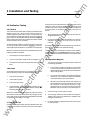
4 Installation and Testing
Page 1 7
4.3 Dielectric Test
When not shipped as part of switchgear, relay panel, circuit
breaker or control, the relay is shipped in a sturdy carton to
prevent damage during transit. Immediately upon receipt of a
relay, check the style number against the requisition and packing
list to see that they agree. Visually inspect the relay for damage
that may have occurred during shipment. If there is evident
damage, immediately file a claim with the carrier and notify the
Siemens Sales Office, or contact Electrical Apparatus Division,
Customer Service. In the event the relay is not to be installed
immediately, store the relay in its original shipping carton in a
moisture and dust free environment. When the relay is to be
placed in service, it is recommended that the verification tests
(given later in this section) be performed prior to installation.
In accordance with ANSI/IEEE C37.90- 1 989 and IEC 255-5,
one-minute dielectric (high potential) tests may be performed up
to 1 500 Vac (45-65 Hz). This applies to all terminals, including the
ports. Note that this device employs decoupling capacitors to
ground from terminals 3, 4, 9, A, and B. Accordingly, a leakage
current of 1 00 rnA (max.) is to be expected at these terminals.
lP
A minimum of 0.2 A in the output circuit is required to ensure
operation of the FUNCTION targets.
Always reset targets by means of the target reset switch.
3.
The relay is a solid state device and has been tested in
accordance with the requirements defined below under
DIELECTRIC TEST. If a wiring insulation test is required on
the panel assembly where this relay is to be installed, it is
suggested that the connecting plugs (or "paddles") of the
relay be removed and the cradle withdrawn from the case
so as not to produce false readings during the wiring
insulation test.
tri
ca
2.
.E
lec
When the connecting plugs are removed, the relay is
disconnected from the operating circuit and will not provide
system protection. Always be sure that external operating
(monitored) conditions are stable before removing a relay for
inspection, test, or service. Be sure that connecting plugs
are in place before replacing the front cover.
Be sure that the relay case is hard wired to earth ground
using no smaller than 1 2 AWG copper wire to the ground
terminal on the rear of the unit. It is desirable to use a
separate ground wire to the ground bus for each relay. If this
is not practical, the number of relays sharing a ground wire
should be kept to a minimum.
ww
w
5.
an
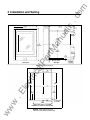
The SCOR relay is supplied in a standard S1 size drawout case.
Figure 4 provides the outline dimensions for th is case. The panel
drilling and cutout dimensions for this case are provided in Figure
5.
The relay does not have to be mounted vertically. Any convenient
mounting angle may be chosen .
ar
Before installation or operation of the relay, note the following
precautions.
4.
4.4 Mounting
tM
4.2 Relay Operating Precautions
1.
ua
ls
4.1 General
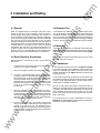
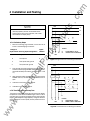
4.5 Connections
The connections for the relay are shown in Figure 6 and Figure
7 . Incorrect wiring may result in damage to the relay. Be sure to
check the model and style number of the relay with the Style
Number Identification Chart (Figure 2) before connecting and
energizing the relay.
The terminals along the top and bottom of the back of the case
are suitable for use with wiring terminals and wire sizes of 1 4 AWG
or larger. The RS-485 port terminals A, B, and C (back of case,
center) require a shielded, twisted pair.
Be sure the relay case is hard-wired to earth ground with no
smaller than 12 AWG copper wire. A ground terminal on the rear
of the case is provided for this purpose. Ideally, each relay should
have a separate ground wire to the ground bus. If this is not
practical, the number of relays sharing a ground wire should be
kept to a minimum.
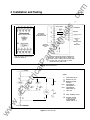
The connections to the current transmormers are shown in
Figures 8 through 1 2. Diagrams are presented for single-phase,
two-phase, and three-phase operation.
.c
om
4 Installation and Testing
ar
tM
an
ua
ls
Page 18
lol
.......____ Mounting Panel
lP
L_--------�--�--------�1-L
FRONT VIEW
Figure 4. Outline Dimensions
1...
�
5.69
{144.5) 2
- - --- - --- - - -�(72�)
- --------
ca
r--o
SIDE VIEW
-
-
-
-
-
-
-
-
-
---
-
-
-
-
-
-
-
0
I
I
I
I
I
!
ct
nl---+- ct !1
.E
lec
tri
I
8.63
{219.1)
'
I
I
;
.
I
I
4.13
: (104.8)
4.31 ::
(109.5)
i
i
ww
w
0
<--
8.25
(209.6)
.__,.,J
-
- ----
-
-------
I
ii
----- -)!- (�7�> ----./
� '\_ (�5P��Js�LA-
-
-
-
-----
6.
(154.0)
MOUNT RELAY USING
,..
--·-·------
0
4 #10 SCREWS
DIMENSIONS IN INCHES AND (CENTIMETERS)
Figure 5. Panel Drilling and Cutout
Dimensions (For Semi-Flush Mounting)
.c
om
4 Installation and Testing
Page 1 9
ua
ls
}
BE1-51 SCOR
®®®®�
@19@17@15@13@11
20 18 16 14 12
Overcurrent
SOLID-STATE PROTECTIVE RELAY
RELAY DISABLED
r--RS-485�
PORT
1
1
FOR SENSING
INPUT TERMINALS,
SEE PRECEDING PAGES
COM
�
COM(+)(-)
GND
SPECIFIED
POWER SUPPLY
INPUT
}
{+
riMED TRIP
(OPTION H) INST 1
(OPTION 1-2)
INST 2
OR
COMMAND CLOSE
OR
GROUND TRIP
tM
9 @@
5 @
3 @
1
@
10 8 6 4 2
®)®)®)®)®)
}
}
(·)
an
C��;��s�
(+)
ar
7
REAR VIEW OF RELAY SHOWING ACTUAL
POSITION OF TERMINALS
lP
DIODES AND RESISTOR ARE INTERNAL COMPONENTS OF
THE RELAY. THEY ARE SHOWN HERE TO INDICATE THE
SOURCE OF DIRECT CURRENT FOR 52b SENSING POWER.
D
2
THE RS-232 PORT IS ON FRONT PANEL ALL OTHER
CONNECTIONS ARE AT REAR OF CASE.
) TRIP BUS
tri
(+
ca
Figure 6. Relay Connections
51
51
3
.E
w
ww
cr------.
52b
lec
5
LEGEND:
51
9
51
OVERCURRENT RELAY
52
TC
BREAKER
52a
INST
1
INST 2
'}
11
51
4
&
51
12
(-)TRIP BUS
Figure 7. Control Circuits
TRIP COIL
BREAKER AUXILIARY
CONTACTS
INSTANTANEOUS
OVERCURRENT #1
INSTANTANEOUS
OVERCURRENT #2
TT
TIMED TRIP
&
RELAY DISABLED OUTPUT
&
REQUIRES OPTIONS
1-2 AND 2-C, PLUS
A PROGRAMMING
CHANGE (SEE PG. 3)
.c
om
4 Installation and Testing
Page 20
All LED and target indicators should be checked in the course
of carrying out these test procedures. Reminder: The FUNC
TION targets require at least 0.2 A in the output circuit to operate.
2.
3.
The tolerances of the test equipment;
2.
By using spot tests that check (for example) only one or two
multiples of applied TAP current at only one or two TAP
positions.
Accordingly, the procedures described below can serve as the
basis for both verification and operational testing.
This procedure verifies the operation of the unit. Check the Style
Number Identification Chart (Figure 2) with the style number of
the relay to identify the options included within the specific relay
to be tested .
Cycle-to-cycle phase stability of the test equipment;
4.7.1 Equipment Required
lP
.
By concentrating on the parameters actually required in the
assigned application;
The tolerances of any external components used i n the test
setup.
1.
ca
1
1.
ar
When test results do not fall within the specified tolerances, the
following should be evaluated.
4.6.2 Scope
ua
ls
The various test procedures which follow are intended to verify
operation of the relay, and to set the various controls for a
specific application. Each phase of a two-or three-phase relay
may be tested as a single-phase device using the procedures
given. Check the Style Number Identification Chart (Figure 2)
with the style number of the relay to identify the options included
within the specific relay to be tested.
an
4.6.1 General
procedure for a newly delivered relay. Succeeding tests can be
reduced in scope to conserve time (and thereby permit more
frequent tests). Such an operational test may be accomplished
by scaling down the verification tests of this subsection as
follows:
tM
4.6 Verification Testing
The current source used in the following tests should have
the following capabilities.
a.
Current output should be switchable so that the test
current can be set before it is applied to the relay. The
selected operating current can then be switched to the
relay's sensing inputs.
b.
The current source needs to be capable of delivering
at least 20 A. This is necessary to test the full capability
of the instantaneous overcurrent element.
c
Because the current levels used to verify operation of
the instantaneous overcurrent element(s) may exceed
the continuous current rating of the relay, it is sug
gested that the current source include a provision for
automatic removal of the test current following a trip.
1.
Time overcurrent pickup;
tri
A complete checkout of the relay (or "verification" test) confirms
that the following are within the published specifications.
Instantaneous pickup;
3.
Time overcurrent timing;
4.
Communications option. (The testing procedure for this
option is covered in Siemens Power Monitor™ Display and
Monitoring Unit (Manual SG-401 8-01 ).
.E
lec
2.
w
While every comprehensive test program should cover all of the
above items, the amount oftesting within any category can vary
over a great range. The operational test defined below illustrates
an appropriate lower limit for this range.
4.7 Operational Test
ww
Confirmation of every parameter within the capability ofthis relay
is usually not practical nor necessary except as an acceptance
2.
A timer accurate t o within 0.001 seconds.
3.
Two test plugs, Siemens p/n 00-871 -854-001 , Basler p/n
1 0095, or GE p/n XLA 1 2A. (Replaces the "paddles" when
testing an installed relay.)
4.
For bench testing: An appropriate AC or DC power source
for relay operation.
.c
om
4 Installation and Testing
ua
ls
Page 2 1
NOTE
BUS
Several proprietary test sets are marketed which
combine the current source and timer, and include
other features to simplify setup.
I
an
51
A
8
Figure
Number
1 st Digit of
Style Number Sensing Input Configuration
K
Single-phase
G
Three-phase
H
Three-phase-with-ground
X
Two-phase-with -ground
tM
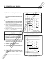
With the connecting plugs removed , connect the unit as
shown in the following figure numbers:
ar
8
A
B
B
c
51
7
i
4. 7.2 Preliminary Steps
1.
I
52
A
I
LEGEND
51
52
,
C
OVERCURRENT RELAY
POWER CIRCUIT BREAKER
LINE
9
Figure 8. Single-Phase Current Sensing Connections
lP
BUS
ca
A
Insert the relay connecting plugs i f bench testing. I f relay is
installed, insert test plugs instead . Before applying power,
check that the Relay Fail contact is closed (terminals 1 1 and
1 2).
tri
3.
12
Apply operating power at terminals 3 and 4 . Verify that the
POWER LED is lit, and that the relay disabled contact is
open.
lec
2.
1 0, 1 1
4.
Load 0 0 into the Phase Tap Cal register.
5.
Load 99 into the Time Dial register.
B
c
I
.E
w
ww
51
A
51
51
B
51
15
51
c
51
18
8
�
T4
�
T7
�
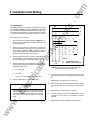
4.7.3 Time Overcurrent Pickup Test
The phase current pickup of the relay will be set at the factory
to operate on one of the two available ranges: HIGH or LOW. If
ground current is monitored, it will also be set for one of the two
ranges. Determine which range applies by noting the indication
of the tap range on the front panel. (One for phase and one for
ground.)
I
52
7
_L_
-
A
B
LINE
C
LEGEND
51
52
OVERCURRENT RElAY
POWER CIRCUIT BREAKER
Figure 9. Three-Phase Current Sensing Connections
.c
om
4 Installation and Testing
4.7.3 Time Overcurrent Pickup Test (Continued)
BUS
Verify time overcurrent pickup as follows:
After performing the above preliminary steps, connect the
input current source to terminals 7 and 8 on the relay case
(Phase A).
2.
Set the PHASE TAP switch to position A.
I
3.
Adjust the input current source to 1 1 0% ofthe value shown
on the front panel table for TAP A {HIGH or LOW range as
indicated by the second digit of the style number) . Observe
that the PHASE A TMG LED illuminates.
an
1.
ua
ls
Page
i
ar
5.
i
Adjust the current source so that the PHASE A TMG LED
goes dark. The current applied when the LED extinguishes
should be between the pickup point (from the table) and 90
times the pickup point.
.
lP
tri
.E
lec
8.
Disconnect the input current source from terminals 7 and
8 (Phase A) and connect it to terminals 1 4 and 1 5 (Phase
B).
Repeat steps 2 through 5 above for Phase B.
w
51
15
51
c
51
13
N
51
18
51
16
LEGEND
B
C
51
52
OVERCURRENT RELAY
POWER CIRCUIT BREAKER
A
c
I
J
52
�
�
51
8
A
51
7
51
14
B
51
15
51
c
51
13
G
17
51
18
�
Repeat steps 2 through 5 above for Phase C .
ww
B
-'--
C) .
1 1 . Repeat steps 2 through 5 above for ground current.
51
14
c
B
Disconnect the input current source from terminals 1 4 and
1 0. Disconnect the input current source from terminals 1 7 and
1 8 (Phase C) and connect it to terminals 1 3 and 1 6
(Ground).
51
7
BUS
1 5 (Phase B) and connect it to terminals 1 7 and 1 8 (Phase
9.
A
B
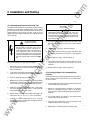
Figure 10. Three-Phase with Residually Connected
Ground, Current Sensing Connections
If this is a single-phase relay, this completes the Time
Overcurrent Pickup Test . If this is a three-phase relay,
perform steps 6, 7, 8, and 9 below. If two-phase-with
ground relay, perform steps 6, 7, 1 0, and 1 1 below. If
three-phase-with-ground, perform all of the following
steps.
7.
��
LINE
ca
NOTE
51
8
17
Repeat steps 3 and 4 with the PHASE TAP switch set to B,
C, D, E, F, G, H, I, and J successively.
A
6.
I
tM
4.
52
A
--
51
16
(
,
A
B
LINE
C
LEGEND
51
52
OVERCURRENT RELAY
POWER CIRCUIT BREAKER
Figure 1 1 . Three-Phase with Independent Ground,
Current Sensing Connections
22
.c
om
4 Installation and Testing
Page 23
ua
ls
4.7.4 Timing Test
BUS
The timing characteristics available by programming the relay
are illustrated in Figures A.1 through A.16. Output trip should
occur as shown for any given TIME DIAL setting, to within 1 0%
or 20 milliseconds (whichever is greater) . Verification of timing
accuracy can be limited to low current levels for convenience.
I
After performing the "Preliminary Steps" (Page 1 9), con
nect the input current source to terminals 7 and 8 on the
relay case (Phase A).
2.
Select the time overcurrent characteristic of choice by
entering its identifying code number into the Phase curve
(Pcur) register. (Reference Table 3.) Similarly load the
Ground curve register with the characteristic of choice (if
ground current monitoring is a relay option.)
a.
2.0 x TAP, and
b.
5.0 x TAP
lec
Adjust the TIME DIAL t o 2 0 and repeat step 4 .
.E
w
ww
c
51
N
51
7
13
51
18
51
16
-'--
LEGEND
B
LINE
C
51
52
OVERCURRENT RELAY
POWER CIRCUIT BREAKER
6.
Disconnect the input current source from terminals 7 and
8 (Phase A) and connect it to terminals 1 4 and 1 5 (Phase
B).
7.
Repeat steps 2 through 5 above for Phase B.
8.
Disconnect the input current source from terminals 14 and
1 5 (Phase B) and connect it to terminals 1 7 and 1 8 (Phase
C).
9.
Repeat steps 2 through 5 above for Phase C .
NOT E
If this is a single-phase relay, this concludes a minimal
Timing Test. Other TAP switch positions may be tried
within the limitations of the current source. If this is a
three-phase relay with ground, perform the following
steps.
51
c
Figure 1 2. Two-Phase with Residually Connected
Ground, Current Sensing Connections
Check the results against the graphed values.
5.
A
17
��
ar
lP
A
Measure the timing from the application of input current to
output contact closure for currents that are adjusted to the
following multiples of TAP:
ca
4.
?
Set the PHASE TAP switch to position A. Load 99 into the
Time Dial register. (The Phase tAP calibrate register is still
at the 00 setting given in "Preliminary Steps. ")
tri
3.
51
8
B
i
tM
1.
I
52
an
Verify timing accuracy as follows:
A
1 0. Disconnect the input current source from terminals 1 7 and
1 8 (Phase C) and connect it to terminals 1 3 and 1 6
(Ground).
11
.
Repeat steps 2 through 5 above for ground current.
.c
om
4 Installation and Testing
Page 24
ua
ls
4.7.5 Instantaneous Overcurrent Pickup Test
NOTE
The phase current pickup of the relay will be set at the factory
to operate on one of the two available ranges: HIGH or LOW. If
ground current is monitored , it will also be set for one ofthe two
ranges. Determine which range your relay is set for by the
indication of the tap range on the front panel. (One for phase and
one for ground.)
8.
Disconnect the input current source from terminals 7 and
8 (Phase A) and connect it to terminals 1 4 and 1 5 (Phase
B).
9.
Repeat steps 2 through 7 above for Phase B.
10. Disconnect the input current source from terminals 1 4 and
1 5 (Phase B) and connect it to terminals 1 7 and 1 8 (Phase
C).
ar
When testing the instantaneous element, the
thermal rating of the relay must mot be
exceeded . The maximum continuous cur
rent rating for each input is five times tap or
20 A, whichever ·is Jess . The one-second
current rating for each input is 50 times tap
or 500 A, whichever is less. For ratings at less
than one second, refer to formula on Page
41 .
an
C AUTION
tM
A
If this is a single-phase relay, this completes the
Instantaneous Overcurrent Pickup Test. If this is a
three-phase relay, perform steps 8 through 1 2 below.
If a two-phase-with-ground relay, perform steps 8, 9,
1 2 , and 1 3 . lf three-phase-with-ground, perform all of
the following steps.
ca
After performing the "Preliminary Steps" (Page 1 9), con
nect the input current source to terminals 7 and 8 on the
relay case (Phase A).
Load .50 into the Phase Instantaneous #1 register. (Appears as Pin 1 in the display, and in Table 3, on Page 1 1 .)
tri
2.
Set the PHASE TAP switch t o position A .
4.
Starting from 0 A, slowly increase the input current source
until the INST 1 output contact closes. This should occur at
3/4 the value shown on the front panel table for TAP A.
.E
lec
3.
5.
Adjust the current source so that the JNST 1 relay opens.
The current applied should be above 71 .25% of the TAP
value (reference the front panel table}.
6.
Repeat steps 3 through 5 above with the PHASE TAP
switch set to B, C, D, E, F, G, H , I, and J successively.
I f Option 1 -2 i s present and i s used as lnst 2 , , follow the
procedures of steps 2 through 6 for testing the Instanta
neous 2 pickup and output.
ww
w
7.
1 2. Disconnect the input current source from terminals 1 7 and
1 8 (Phase C) and connect it to terminals 1 3 and 1 6
(Ground).
lP
Verify instantaneous overcurrent pickup as follows:
1.
1 1 . Repeat steps 2 through 7 above for phase C.
1 3. Repeat steps 2 through 7 above for ground.
4.7.6 Testing of Option 1 -2 Command C lose
Function
This function can only be used and tested if the Communications
Option is present, and a Power Monitor unit or Power Monitor
PC unit is present.
1.
Close the 52b contact input on the relay (terminals 3 and 9)
which simulates the open breaker.
2.
Select the "Command Close" command in the Power
Monitor. For detailed instructions refer to the Siemens
Power Monitor™ Display and Monitoring Unit (Manual SG401 8-01 }.
3.
You should observe the closure of the programmable
output contact (terminals 5 and 6).
4.
Open the 52b contact input. You should observe the
programmable output contact open.
5.
Repeat step 2 . Terminals 5 and 6 should not close.
.c
om
5 Maintenance
Page 2 5
5.3 Timekeeping
Static devices require no preventive maintenance other than
a periodic operational test (see Page 20). If the relay fails to
function properly, contact Siemens Customer Service. When
returning the relay to the factory, ship the entire relay cradle
assembly, preferably in its case.
The real-time clock within the relay, once set by the Power
Monitor unit after power up, maintains time to a resolution of 0.01
second ; however, drift within the clock can be as much as 0.5
seconds per day. In order to keep all of the clocks in the system
in proper synchronization, the Power Monitor periodically broad
casts the correct time.
5.2 Storage
Note that changing the time within a relay by seconds or minutes
can upset instrumentation functions such as demand calcula
tions.
ww
w
.E
lec
tri
ca
lP
an
ar
tM
This protective relay contains aluminum electrolytic capacitors
which generally have a storage life expectancy in excess of ten
years at storage temperatures less than 40° C. Typically, the life
expectancy of the capacitor is cut in half for every 1 oo C rise in
temperature. Storage life can be extended if, at one-year inter
vals, power is applied to the relay for a period of 30 minutes.
ua
ls
5.1 General
.c
om
6 References
Page 26
2.
Siemens Power Monitor™ Display and Monitoring Unit
(Manual No. SG-401 8-01 ) .
3.
Siemens SCOR Protocol.
4.
Siemens Isolated Multi-Drop™ RS-232 to RS-485
Converter(Manual No. SG-6048).
5.
Siemens Power Monitor™ PC User 's Guide (Manual No.
SG-4028).
ua
ls
EIA Standard: EIA 485. (Also known as the RS-485 Stan
dard .) Published by Electronic Industries Association (April
1 983).
ww
w
.E
lec
tri
ca
lP
ar
tM
an
1.
.c
om
Appendix A T ime Overcurrent Characteristic Curves
ua
ls
Figure A.1 through Figure A.16 illustrate the characteristic
curves that are programmed into the nonvolatile memory of this
relay.
Note that a drawing number is given under each caption. Use this
number to order a full-size (1 0" x 1 2") Characteristic Curve set.
ww
w
.E
lec
tri
ca
lP
ar
tM
The Phase and Ground Instantaneous Time Curves are pre
sented in Figures A.1 7 and A.1 8 respectively.
an
Refer to Table 1 on Page 5 for a listing of the 1 6 characteristic
curves.
Page 21
.c
om
Appendix A Time Overcurrent Characteristic Curves
lOO
200
200
100
10
10
10
10
10
10
50
�
!-
_,
"""'
-t- ,
�
!-
.4
ca
.5
'l\.\ l\��!'"' !'t'--"""""'"'
' ""'
'l ,\..
"
""
."l.
\. �'
..
'
'l\
"
"'
' �
'� ' ""-
.2
"""
1""
"""
!'.
\��
...
�I'...
1'\\���
.."'\
"""
�"""
.E
lec
1
.01
.01
""'
.07
�
88
::"�
80
......
""""" r- 60
50
-...... 40
-.....
30
r-- � 20
tri
.I
�' � ·""��'r-.
lP
\ �� ' :"'-
..
7
10
I
•
7
•
ar
0
I
A
L
,"'
-' •'\.1\.
\t\\.. ."'
...
'l
tM
T
I
M
E
\
\'
1
.I
\ \..
�
20
10
I
•
(f)
0
z
0
(_)
w
(f)
�
w
::::2:
i=
' •'' I'
..
'
lO
20
"""'
� I'
.Oil
-
83
--- - 02
01
00
.04
.... �
�� f\1\. I'-I'
L�
� ""'
.......
r-... �""r- t-... r- 99
!'
r-...""'""'r.... ""
'
\.1 \.
�
'
' 1'-"
"""
1\
r- 80
t--".......
"""-
60
50
40
r-. 30
""""
- 20
I"
I""
"""
\ 1\ ·"' 1"'1
' ·'["'
\ I\ ...I'!I'
I "�
1
�
....,...
!'
r-...""'""'r-
!'-,._
::
.7
.I
I""'
.5
.4
r--"""-.
!'-"....
""""
03
02
-r- 01
J-oo-- 00
1
.01
.01
.07
.01
.Oil
.04
. 02
. 01
1
J
4
5
•
1 • 110
20
.5 .• . 7 .
• .•
1
J
4
5
I 7 8 t10
20
MULTIPLES O F PICKUP SETIING
MULTIPLES OF PICKUP SETIING
Figure A.1 Timing Type b1 : Short Inverse Time
(Owg. No. 1 8-752-294-001 )
Figure A.2 Timing Type b2: Long Inverse Time
(Dwg. No. 1 8-752-294-002)
ww
07
-
.2
.02
10
r---r- 05
.3
.OJ
w
"
l"-
--" � � .:'II
'
"
' I"'' I"'
8
.OJ
.01
.5 .1 .7 .I . I
I'
\ "'I\.!'-�"'
\
0
I
A
L
--....
....,r-..
- .. .
...... 1 0
r--""..
" looo-.
07
.....
. 01
5
z
0
(_)
w
(f)
z
w
::::2:
i=
E
� ��
� l\.. "'
40
lO
I
M
' '
--" L\.
50
40
T
}
an
100
10
10
ua
ls
lOO
Page 2s
.c
om
200
100
10
10
70
100
10
10
70
10
10
an
200
�
�
40
40
20
0
I
A
L
0
I
a
7
'"
•
' ' \..
"'
''
"'
a
4
99
80
60
50
40
lP
' ''I'
.. 1\.
'I'""'
r'\. ' ""'..�
2
' """'!"- ..�
\
1
I
•
7
' "" I'.
......
!\,.
.....
" .....
.. "'
.
.
�
20
.]
""'
'"
.2
r"'-o ""�
�
"" �
.E
lec
1\. I...., �
1' �
I
.oe
.01
•
7
•
5
to-
�--
(/)
0
z
0
(_)
UJ
(/)
z
UJ
�
F
01
00
.07
.4
.
.02
w
�
"'
""
f"''ii
!liiiO:
1
.oe
.oe
.07
.03
ww
�
"'
"- ,,
..... 99
80
.....
-r-...
60
-I'r- 50
.....
....... 40
�'- I'-...
... ...
r-- 30
�
t'"-....
� 20
"
.03
.
20
"
.....
01
•• .• . 7 •••• 1
l
!'iii;
"'
1-. ,...
"
""""""'
.2
.04
a 7 a 1 10
'
' 1""
3
.04
5
"
"
"'
.oe
•
""
iii
�
"Y � .....
\ '
.5
.oa
J
0
I
A
'
'� "
� '�
�
.I
08
.. .. 1
���t\
"
.7
.oe
.01
•• .• .7
E
���
1
I
·•
.
02
�
� ��
'\�
\ \\r\
2
.
�
�
�
�'
J
10
07
05
03
02
tri
.4
30
ca
0
(_)
UJ
(/)
z
UJ
�
F
0
•
4
,,,
J
\
20
ar
"
I
�
tM
I
�
E
T
'
T
�
z
Page 29
ua
ls
Appendix A T ime Overcurrent Characteristic Curves
l
4
�
-...... 1 0
07
'"""'
r--. 05
""'- 03
!'---...
r--... �
�'- r--... �
I 7 I 110
20
MULTIPLES OF PICKUP SETIING
MULTIPLES OF PICKUP SETIING
Figure A.3 Timing Type b3: Definite Time
(Dwg. No. 1 8-752-294-003)
Figure A.4 Timing Type b4 : Moderately Inverse
(Dwg. No. 1 8-752-294-004)
02
01
00
.c
om
Appendix A T ime Overcurrent Characteristic Curves
-
200
-
100
ID
•
"
ID
ID
10
ID
ID
\
� l"
.\1\.\
\� �
\
����
I
" "
!'-
" "
l"
r-- 99
!" ""'
80
" ""' t'--o....
60
"' ""' r-...
50
-�
� 40
""""
�"""
t"--- to... 30
"
' "
\ 1\\
� ,\' ·' "
\�\' �l\
...... to...
I'
"
I'
,,
" \"
.I
.7
' 'l'l\
.I
-�
..
1\,.
I' ,....,
-
20
""'
""'
--
tri
.3
ca
���!\
\
I
.I
1\
� ,..
� ....,...
. .
l"o
.E
lec
2
��
1
.oi
10
I
I
7
•
�
-'
�
-
""'"
rr---�
r--.�
..
.Ill
·. 7
o
M
\L\
_\ l\.
..� l\)l\
...!
I
.I
0
�"��"
..
"
.I
L.._
I'
1'1 �
l"iii:
"'
''
-
F:::
I'll.
1\
"""'" 30
l\..
1'1\.
�
�
t
.oi
Ill
� �
10
� .......
07
......
!'--- OS
���
::
� ��� ::::�
.
.
07
.
.Ill
.
.00
.01
.0 4
.o4
.OJ
I
..
.01
ww
w
.01
.I .I .7 .I .I I
MULTIPLES
J
•
�
• 1 • 110
OF PICKUP SETI I NG
Figure A.5 Timing Type b5: Inverse Time
(Dwg. No. 1 8-752-294-005)
20
...
.. .. . 7 .1.1 1
MULTI PLES
J
99
80
80
50
40
20
"
.2
I"
� � ""
" " N'too !'-.........
" " �!'""
!'---
' '
.4
A
L
IV' l'\
�
\��
.I
I
��
!\ � I'
.,
.7
10
07
05
03
02
01
00
�
"
( �'l\'
i=
I
..
E
-' ._}. � -'
,,
�
z
0
0
llJ
(/)
z
llJ
�
T
\� �
_\ �' �
•
lP
I'
�
·.
I
A
L
" ,,
\ \ 1\ �'[\.
,,,1\
'
I
7
(/)
0
z
0
0
llJ
(/)
z
llJ
�
i=
0
..�
ar
10
" �"
�n
..
E
��'�
20
_.1.
40
T
I
.� •"
_\
an
•
�
.0
tM
50
ua
ls
.JOO
Page 3o
4
I
I
7 I 110
•
OF PICKUP SETIING
Figure A.6 Timing Type b6: Very Inverse Time
(Dwg. No. 1 8-752-294-006)
I
.c
om
\i
�\
\
�
100
.,
.,
111
100
10
ID
111
"
"
, \\
40
�
\
30
20
,
\
50
"' �'
,\,1\"
.\
�� �
�'\�' .'\
20
����
,,,
\ ,,
I
�n
·' '-' :\
�
'
\'� ;'\'\
\' �� ��
\.\ '\\\
�
1
..
.7
E
�·
��
''\�
� '\!"\� �,.....
99
� \�'�" �........
.. ... 80
,,,
[
��
,, ' 1\- 1\
.
.
..
'II:
�
��
60
50
40
......
'- ....... 30
"'
20
"'
.......
tri
..
I'..
0
I
A
L
ca
'
.I
...
�
� '\
'
\ \\1\ \ �
' \� \
(f)
0
z
0
(_)
w
(f)
�
w
�
F
I
.3
"
.2
�
lec
r\ "�
1'1"""
.1
01
.01
.rn
.
.oa
·" r-.... 1 0
f'.."�'...
"'
07
�""r-... 05
�
� 8�
.......
01
00
(f)
0
z
0
(_)
w
(f)
�
w
�
F
I
.\' '
T
I
.,
...
,,
'
E
'�
(
.
.�
..
.3
0
�I\
'
I
,\.
.n
A
L
,,
\ '
�"�
�
:\:\ \
'
[( 1"\.1\.
'
99
80
' ,, ·'' 80
' .\"\: 50
' \" 40
' 30
"\.
�\ _\.
20
[\.\
�\\
�\ ��
1\ 1\\\ \
� ��' �'
.2
......
.oa
1 I 110
20
.01
.a
10
�� 8A
�
01
.1
.01
.01
.rn
.02
5
,
,
'
.
.02
4
'
l\
�
1\
.I
.1
.04
3
'
\�\
1
.I
.OJ
.I .7 .1.1 1
\
\ ��
.04
.111
.a
�\ ��� �
..,
'
'
' ,,
\ '\ :-'\I'(\
' """�
3
.OJ
w
ww
I
s
l\ \ ' ��
,,
.Oil
.E
.06
10
I
I
7
ar
•
T
lP
�
.� � �
' ,,
�'
' '
� \' � �
l' �,1,
..
.
40
\ \ � ��
� '�'
10
•
\ ,,,
1 \\' '
an
�·
50
10
��
tM
10
Page 31
ua
ls
Appendix A T ime Overcurrent Characteristic Curves
.I .7 .1.1 1
3
.
5
1
7 1 110
MULTIPLES OF PICKUP SETIING
MULTIPLES O F PICKUP SETIING
Figure A.7 Timing Type b7: Extremely Inverse
(Owg. No. 1 8-752-294-007)
Figure A.8 Timing Type b8: H
(Owg. No. 1 8-752-294-008)
Ill
00
.c
om
Appendix A T ime Overcurrent Characteristic Curves
ua
ls
JOO
-
....
...
�
-
1:
...
100
10
10
'' ,,
10
50
10
50
....
'
1'- · ' �'
\.1\. � ,,
' N� '
�
....
10
•
I
7
....
'
·'-
I
....
\
,,
�' \
�
\\�
M
"
'
E
,\.�
' ,,
' ,, '
,.
�'
..
.7
..
\
,,
\
��
i\.I\ I\
.�
.4
I
,,
\.\.
�
A
L
�"�
��
99
_1 � 80
' ' ,,,
' ·'� 60
\. \\.' 50
40
' ' 30
"' '
ll' ' 20
[\_\.'\.
ca
\ ��
�
'
tri
\.
.J
'
1\
1\
.E
lec
.2
,
.CII
.jll
.07
.CII
.00
,
�� :\.'
"-
02
" 01
"" oo
.I
.7
w
ww
7 • 110
�
..
.&
.4
.J
�
T
I
["\.,
.,
M
l\ � l'
1\. 1\.1\."
E
Ill
0
•"
'
,\\.
1\1, �\\
I
� 1\1\ �\"I\
� �
�
�' �
A
L
99
,, 80
' " ,,,
.._, l'
\. \.\: 60
,\1\1\.1\
\. 1\.\' 50
111..
'
' 40
' 1"\.
1'·' ' ' JO
' 1\ [\.\.'
20
" � 1\"'"'
.2
� �,,�
��'
.1
.CII
.CII
..,.
'
.07
.01
.00
. 04
.01
•
���
1
.01
�
,,1'""""'! "\.: ,,,,
\ � [\.1\.
� 'I� 1\
-
..
.01
4
\.'I\. 1\
\ �·�
.03
J
���
' \'
5
Cf)
0
z
0
0
w
Cf)
z
w
�
F
I\
'
•
.03
.. . 7 .1 .1 1
"""
\r\��
10
�� �j
.04
�
-
10
•
I
7
0
'
\. \. �\. i\.
' '�
1
.I
T
I
tM
' \ \:��
l'
'l\ �''
20
ar
-
20
50
lP
50
..
..).,
""""' 1"\."
'�'
\. ��
40
40
Cf)
0
z
0
0
w
Cf)
z
w
�
F
"'\. �\.
an
10
""""'
l"\.
.. "' '
•
10
[\."\"1 ,\.'
.... \' � �
Page 32
.01
.• .• . 7
••
.
.
1
J
4
5
t
1 I 110
MULTIPLES OF PICKUP SETIING
MULTIPLES OF PICKUP SETIING
Figure A.9 Timing Type c1 : J2T w/Limit 1
(Dwg. No. 1 8-752-294-009)
Figure A.10 Timing Type c2: 12"f w/Limit 2
(Dwg. No. 1 8-752-294-01 0)
10
I
.c
om
Appendix A T ime Overcurrent Characteristic Curves
ua
ls
-
100
10
10
10
.....
·�
so
�
an
70
40
'-L'
'r\ ��
r\� 1\�
-
1""--o
10
I
•
1
1'-
- .,1,
\.�
•
•
�
���
['
T
I
l'
M
E
l\.
''
'
..... l\.I\.I\
......
,1\:
' ��
0
(_)
LU
U)
�
LU
�
i=
.......
��� �
.•
.1
I
�� �''
� � �'" \
�� ��
'
� I\.
..
.
0
A
L
gg
eo
�' ""
'"' '"� 80
\. \\: 50
' 40
'
l'' ' 30
1'\.\..
20
� \.. 1\
ca
1
.I
�'
l"-
'
lP
�
z
.
..
tri
1\.
.J
I'
I'
.E
lec
.2
tM
-......
1\. l�
1
.01
.01
�\: �
��
.07
T
I
M
E
ar
-....
Page 33
' "'"'
'
.......
.01
.01
.04
.QJ
U)
0
z
0
(_)
LU
U)
�
LU
�
i=
' 1\
['
-,
.2
10
f'
' :D. 80
' ' ,,,
' n: 80
\. \" 50
40
'
30
�'' '
1\.'\.' ' 20
l\,�, 1\
H-+++t--+-H--+++-1-+--Ht-MM�
I' �
� �'
��
�
' ''
'
"
10
I
01
00
.02
ww
w
.01
.• .• . 1 .1.1 1
l
4
5
I 7 I 110
20
.01
L.J....L.l...LL-�.L_J_..L..LLJ._J..L.L..LJ-..-..-
Ill
J
4
5 • 7 • 111
7 A .I 1
.. A .
MULTIPLES OF PICKUP SETIING
MULTIPLES OF PICKUP SETIING
Figure A.1 1 Timing Type c3: FT w/Umit 3
(Dwg. No. 1 8-752-294-01 1 )
Figure A.1 2 Timing Type c4: FT w/Limit 4
(Dwg. No. 1 8-752-294-01 2)
.c
om
-
-
-
-
11
1011
•
•
'Ill
•
'Ill
•
•
•
an
•
40
•
��
1\�
..
�
E
,,�,
J
1\.
1\�
�
I'
I
D
I
l'
1n
A
L
lP
l\1' L\'"'
1\ 1\ �\'1\
�l\ �
"�
1
��
"
80
eo
� I\� 50
_, 40
' ,,
30
·' ' '
1'\.'\.'
20
' �
[ ' ' l''
' "
ca
.I
"
.I
.7
..
l' "
-�
4
1\.
tri
.3
J
0
u
UJ
(/)
z
UJ
lec
.ai
I
.01
.07
.01
.01
'�
:"
�
.E
04
��
-��
&
�
t=
w
ww
1\ 1�
"
l
4
�
I 7 I 110
I
1n
A
L
L\\\
�� ��
.I
·'
.I
.4
.3
"
10
eo
'\. 1\'\.: 50
40
' '
30
·'' �
1\.'\.' '
20
' ('\.
[' ' '"
' ""
.7
'
�
�
�'"' �
�' �
��
I
.ai
01
..,
......
"
.
.01
..
..
.
.01
7 .1 .1 1
D
'-'
.I
.02
.
E
�
1\
1
.I
••
. 1 .I
I
..
t\ " �,1\
.113
01
T
l'
•
�
z
�
'
�� 1\.
I' � �' 1 0
2
.
�
10
•
I
7
ar
•
�
.
T
I
tM
�
��
I
0
u
UJ
(/)
z
UJ
�
t=
I'
•
r"''
10
I
I
7
�
z
Page 34
ua
ls
Appendix A T ime Overcurrent Characteristic Curves
...
.I .I .7 .1 .1 1
J
4
I
I 1 I 111
MULTIPLES OF PICKUP SETIING
MULTIPLES OF PICKUP SETIING
Figure A.1 3 Timing Type c5: 12T w/Limit 5
(Dwg. No. 1 8-752-294-01 3)
Figure A.14 Timing Type c6: 12T w/Limit 6
(Dwg. No. 1 8-752-294-01 4)
•
10
I
00
.c
om
Appendix A T ime Overcurrent Characteristic Curves
-
100
10
10
7V
100
10
10
7V
10
10
so
so
an
-
40
40
30
1'\
1\
20
��
I
I
7
T
I
I
{" I\
' '
""
�
\'
\
' �'
I
A
�\\
L
,�
�\"'
� ��
gg
80
' ' •''
'- '-\.: e0
\. '' 50
'
' 40
·','\." � 30
1\.\.'
20
�\.'t\
�'� 1 0
ca
1
,'\.
.\.\.
lP
l
.I
..
.?
..
� \
-�
.4
0
(_)
UJ
(f)
�
UJ
�
F
'
1\
.E
lec
.2
.1
..
.CII
I'
��
07
.
'I"''I.:
i"o..
.CII
.01
.04
.Ol
w
•
.
.
7
1
.
.1
1
l
4
�
I 7 I 110
E
D
\'
.?
..
\. \
-�
'
.4
3
�
.1
.01
gg
80
eo
\. \\." 50
c'\.
_'\. 40
' �
' ' ·''
'- '-'-'
'
•'- "
'
.2
'
" 30
i\.\.'
20
�"'t\
�'�
��
' I'll.'
-"
�
01
.07
.
L
�\\
' ��
1
.I
.
A
""
\ ,� �"\
�'
..
.
I
''"
'
01
.01
.04
.
Ol
.02
.02
.01
.I
I
I
..
"""\ \.'
�
z
tri
�I\;
.3
ww
•
I
D
T
1'\.
I
I
7
M
E
,,
�
."\'�
I
�
10
ar
10
tM
20
(f)
0
z
0
(_)
UJ
(f)
�
UJ
�
F
ua
ls
-
Page 35
20
.01
.I .I .7 .1 .1 1
l
4
I
I 7 I 1 10
MULTIPLES OF PICKUP SETIING
MULTIPLES OF PICKUP SETIING
Figure A.15 Timing Type c7: !2T w/Umit 7
(Dwg. No. 1 8-752-294-01 5)
Figure A.16 Timing Type c8: FT w/Limit 8
(Dwg. No. 1 8-752-294-01 6)
20
10
�
.c
om
Appendix A T ime Overcurrent Characteristic Curves
ua
ls
SCOR INSTANTANEOUS TIME CURVE
GROUND TIMINGS
SCOR INSTANTANEOUS TIME CURVE
PHASE TIMINGS
70
50
\
\
�
z
\
8
w
(/)
3
�
\
1'.
H-+++-H""+++-H-+++-H-+-H
30
1-t-+-+-+--t-+-+-+-+--t-+-+--t-1
�_L_L��_L_L��_L-L��_L�
18
20
2
4
6
8
10
12
14
16
1'-
l 51
"
SCOR
D992-oo7
1 -22-92
tM
0
w
:::;;
>=
an
\
60
� 40
sw
Page 36
I"
....
:1:: 50
sw
0
w
:::;;
>=
ar
MULTIPLE OF TAP
ww
w
.E
lec
tri
ca
lP
Figure A.1 7 SCOR Instantaneous Time Curve
Phase Timings
30
2
4
6
8
10
12
14
16
18
20
MULTIPLE OF TAP
Figure A.1 8 SCOR Instantaneous Time Curve
Ground Timings
.c
om
Appendix B Functional Description of Operation
Page 37
8.2 Current Sensing
The solid state power supply is a low burden, flyback switching
design which delivers a nominal +5 and +1-1 2 Vdc to the relay's
internal circuits; also an isolated +5 Vdc for the communications
circuits.
The input terminals of the power supply are not polarity sensitive.
A red POWER LED illuminates to indicate that the power supply
is functioning.
tM
The SCOR relay can be provided for single-phase, two-phase
with-ground, three-phase, or three-phase-with-ground current
monitoring. The illustrated relay is of the three-phase-with
ground style.
B.3.1 General
an
The SCOR relay is a microprocessor-based overcurrent relay
that can optionally be equipped to communicate with a remote
computer. The following text is referenced to Figure 8.1 ,
which is a functional block d iagram that illustrates the overall
operation of a fully implemented version of the relay.
ua
ls
8.3 Power Supply
8.1 General
A loss-of-power circuit monitors the power supply. If power is
interrupted, a Power Fail signal is delivered to the computer in
time for it to store all vital information in non-volatile registers. Also
at this time, the Relay Disabled output contact closes as ex
plained below under "Outputs. "
lP
ar
The internal current sensing transformers are designed to receive
their input frorn the 5 A nominal secondaries of standard current
transformers (CTs) . Note the dual primaries of the internal
transformers. One or the other is connected by the factory to
obtain a LOW or a HIGH current sensing range (0.50 to 5.0 A, or
2 .00 to 1 1 .00 A) in accordance with the specified Style Number
of the relay.
B.3.2 Loss-of-Power Sensing
ca
The outputs of the internal transformers are applied to scaling
circuits (one for each of the phases, one for ground) that convert
each of the input currents to a voltage level that can be utilized
within the relay.
tri
A "coarse" incremental adjustment for the current pickup setting
is provided by the TAP switches. These are front-panel rotary
switches; one for the phases, and another for ground, if ground
current is monitored. The current setting represented by each of
the 1 0 switch positions is given for each range (HIGH and LOW)
in the table printed on the front panel. (Reference Figure 3.)
.E
lec
The "fine" adjustment of the current pickup point is determined
by the value (0 to 99) stored in the relay's Tap Cal registers (again,
one setting for the phases, one for ground). When the Tap Cal
register contains the value 0, the pickup setting of the relay is the
indicated TAP setting.
ww
w
The Tap Cal registers provide a means of adjusting the timed trip
pickup between the selected position of the TAP switch and the
next higher position. For example, when the TAP switch is set to
position A, the Tap Cal register provides an adjustmentfrom 0. 50
to 1 .00A forthe LOW range, and from 2.00to 3 .00 A forthe HIGH
range. EXCEPTION : At the highest TAP position (i.e. , J), the
setting of the Tap Cal register is ignored. Therefore the J values
of 5.0 and 1 1 .00 represent the upper limits ofthe LOW and HIGH
ranges, respectively.
8.4 Multiplexer
A multiplexer is utilized to select each current sensing input.
These inputs are then supplied to the sample-and-hold circuit,
and then to the level shifter. The level of each input sample is
strobed into the microprocessor, where analog-to-digital con
version is implemented.
8.5 Internal Microcomputer
The onboard computer fulfills many of the logic and signal
processing functions described in the following paragraphs, and
performs the time delay computations.
B.5.1 Analog-to-Digital Converter
The voltage representing a component of the actual sensed
current is presented to the analog-to-digital (NO) converter. The
NO converter supplies the equivalent binary value of the sensed
current. The accummulator stores a number of these squared
samples and presents this sum to the trip computer. The
microcomputer then calculates the true RMS value ofthe current
at each input.
B.5.2 RMS Sensing
The SCOR protective relay uses RMS Sensing, a technology first
introduced by Siemens in 1 985, to sample the current wave
shape and quickly calculate the effective heating value of the
current. SCOR relays evaluate the impact of harmonics and
provide accurate circuit protection. The SCOR relay uses a sum
.c
om
Appendix B Functional Description of Operation
Page 38
The current inputs are continuously polled and the calculations
updated once for every 60 Hz (line) cycle. As long as the sensed
current is above the pickup point, the elapsed time is accumu
lated toward trip. However, once the sensed current falls below
pickup, the relay is reset and all accumulated time is cancelled.
8.5.3 Time Overcurrent Calculations
When the value of a sensed current exceeds the pickup setting,
the TIMING LED for that phase will light. The LED will stay lit as
long as the sensed current exceeds the selected pickup level.
an
8.5.4 High/Low Range Register
It was noted earlier in this section that the input transformers
must be wired for one of two sensing ranges: HIGH or LOW. This
information is recorded (at the factory) into the HI/LO Range
.E
lec
tri
ca
lP
ar
tM
If the magnitude of the current exceeds the pickup setting, the
microprocessor calculates the required time delay by evaluating
the magnitude of the overcurrent in the context of the desired
time overcurrent response curve. (All of the time overcurrent
functions that are graphically illustrated in Figures A.1 through
A.1 6 are in the computer's memory.)
ua
ls
of squares algorithm for both determining trip level and for
calculating metered values of the relay current level. The input
waveform is sampled several times to determine instantaneous
values. These instantaneous values are processed to obtain the
true RMS value of the input current.
Operating
or
Close
POWER
SUPPLY
Loss-Of-Power
Detector
Relay
Fail
ww
w
Power
nst 2
Figure 8 . 1 Functional Block Diagram
.c
om
Appendix 8 Functional Description of Operation
(assuming that the Communications Option is also present) . The
programming information is supplied in the Siemens Power
Monitor™ Display and Monitoring Unit (Manual SG-401 8-01 ) .
(The second output relay, when controlled by the computer,
cannot simultaneously serve as an instantaneous output .)
ua
ls
Registers;one register for the phases, one for ground. All current
sensing and pickup data is weighted by the computer accord
ingly.
8.5.5 Watchdog Circuitry
8.6
an
Optionally, this extra output relay can be programmed as a
dedicated ground trip contact.
8.7
Target Indicators
Targets are provided for each function (TIME, INST 1 , and INST
2/CLOSE or GROUND), and for each phase and ground that is
monitored on multi phase relays. Each target indicator is visible
on the front panel of the relay with the cover in place. When
operated, the disk in the target changes from black to orange,
and is magnetically latched in this position .
tM
The watchdog circuit checks that the microcomputer is opera
tional. If some transient condition has d isrupted its normal
pattern of operation, the watchdog will momentarily close the
relay disabled output contact, reset the computer, and reinitialize
the program. The computer is then restarted , and the relay
resumes its monitoring function (without human input).
Page 39
Outputs
8.6.1 General
The FUNCTION targets only operate when a minimum of 0.2 A
flows through the associated relay's output circuit. This is to
provide confirmation that the contact actually did close and that
a signal was delivered . The ELEMENT targets, i.e., phase and
ground are internally operated .
8.6.2 Relay Disabled Output
lP
ar
Although the output relays are controlled by the microcomputer,
the output interface contains the transistors that energize them.
With the exception of the Relay Disabled contact (described
below), all of the output contacts are of the normally open type
and have targets associated with them.
tri
ca
The Relay Disabled output contact is of the normally closed (NC)
type. It is held open (by the output relay's energized coil) at all
times after power-up unless a malfunction is detected as noted
below. (This arrangement provides for a fail-safe output signal,
since the contact is able to close an external alarm circuit even
in the absence of power.)
1.
2.
.E
lec
The Relay Disabled output contact will close if:
To monitor output current, the coil of a special reed relay is
placed in series with the output contacts. The reed relay signals
the target. (The series impedance of the reed relay coil is less
than 0.1 ohm.)
To reset the target(s) after an abnormal system condition has
been cleared, manually raise the target reset switch on the front
of the relay, or its extension bar that protrudes through the
bottom of the cover. (The relay must be under power to reset a
target.)
The power supply voltage falls below requirements; or
NOTE
The upper connecting plug ("paddle") i s removed .
Additionally, the Relay Disabled output contact will momentarily
close if the watchdog circuit detects abnormal operation of the
computer. (Actually, detection of abnormal operation leads to
microcomputer reset in an effort to correct the problem, and the
reset operation causes the contact closure.)
w
8.6.3 Instantaneous and Command Close Options
ww
One or two instantaneous outputs are available as options. The
trip points for these options are selected by a programming
method described in Section 3, Operation by Front Panel.
When two instantaneous outputs are selected, one of them can
be programmed to operate directly from the system computer
Resetting the targets in this manner will not reset the
alarm messages provided on the communication link.
8.8
Communications Option
The SCOR relay includes provision for the future addition of the
optional communication board as standard . If the communica
tions option 2-C is selected initially, the relay is provided with an
RS-232 port on the front panel, and an RS-485 port on the back
of the case.
.c
om
Appendix B Functional D escription of Operation
Use of this port is restricted to Siemens field service and factory
personnel, and connection to this port automatically disables
remote RS-485 communications.
8.8.2 Local or Remote with Siemens
Power Monitor™ Unit
Configuration of the SCOR relay is read and stored by the Power
Monitor unit, and the relay can be configured or changed
remotely from the Power Monitor unit (except for the tap
switches which must be set manually on the front panel).
Configuration and changes from the Power Monitor unit is
password protected.
tM
The RS-485 port permits interconnecting multiple SCOR relays,
4700 power meters, Static Trip IIIC trip units, and other compat
ible devices via an industry standard shielded twisted-pair EIA
RS-485 communication bus to a Siemens Power Monitor™
display and monitoring unit. A Power Monitor unit can accom
modate up to 64 devices. The bus length can be up to 4000 feet.
The Power Monitor unit is intended to be a "factory floor" tool,
and can be mounted on medium-voltage or low-voltage switch
gear, serving all circuit breakers within a substation or controlroom,
or it may be located remotely at a central maintenance/control
area.
ua
ls
A 9-pin RS-232 communication port is provided on the front of
the relay for local data readout and programming when the
communication option is installed.
system diagrams with real-time amperes and circuit breaker
position; detailed data for all phases and ground simultaneously
which changes to a trip log with time stamped currents at the
time of trip, relay target operation plus watchdog status; a MIN/
MAX log; and an event log with a time stamped chronological
listing of events of all devices on the bus. The event log is a
powerful tool for operating and maintenance personnel.
an
8.8.1 Local RS-232 Port
Page 40
ar
For complete operation of the SCOR relay with a Power Monitor
unit, see the Siemens Power Monitor™ Display and Monitoring
Unit (Manual No. SG-401 8-01 ).
8.8.3 Local or Remote by Owner's Computer
lP
Installations which do not have a Power Monitor unit can use a
computer equipped with Siemens Power Monitor-PC program
connected through a Siemens Isolated Multidrop™ RS-485/RS232 converter. If the SCOR relays and other devices are
interconnected by the communication bus described above,
the computer can access all devices, and display the same data
as described for the Power Monitor unit. This can be helpful
when initially configuring a system which has multiple devices,
and for periodic downloading of event and MIN/MAX data. For
information about operation with the Power Monitor PC, refer to
the Siemens Power MonitorPC™ User's Guide (Manual No. SG4028).
ww
w
.E
lec
tri
ca
The Power Monitor unit works intimately with SCOR relays to
provide comprehensive displays, monitoring, and logging of all
the data from all devices on the bus. It is a dedicated computer
which constantly monitors each device on the communications
bus. Every data item available from the front of the relay is also
available at the Power Monitor unit. The Power Monitor unit also
provides information not available on the SCOR display, such as
.c
om
Appendix C Specifications
The SCOR relay is available in single-phase, three-phase, two
phase-with-ground, and three-phase-with-ground configura
tions, and with the features and c a p a b ilities descri b e d in
Table C.1 .
Specifications
an
Table C.1
ua
ls
Page 4 1
The unit is designed to operate from the secondary of a standard current transformer
Current Sensing Inputs
rated at 5 A. The maximum continuous current rating for each input is five times tap or
20 A, whichever is less.
tM
The one-second current rating for each input is 50 times tap or 500 A , whichever is
less. Ratings at less than one second are calculated as:
=
=
=
Time that current flows (in seconds)
ar
K
T
{Klf where
(500 A or 50 times TAPt
Less than 0.025 ohms per phase at nominal 60 Hz. (see
Frequency (nominal)
60 Hz.
Table 3)
lP
Current Sensing Burden
Time Overcurrent
Two ranges are available: HIGH (2.0 - 1 1.0 A}, and LOW (0.5 - 5.0 A). Range is
ca
Pickup Ranges:
independently specified for phase and ground by the second digit of the Style
Number. The TAP range windows on the front panel indicate which range (HIGH or
LOW} is specified. Selection of the desired tap is made using the rotary selector
switch(s) on the front panel. Refer to the table on the front panel for the various tap
lec
Pickup Adjustment:
tri
ratings in secondary amps.
Incrementally adjustable over the selected range by a front-panel (TAP) selector switch
("coarse"), and by numerical data entered into the Tap Cal register ("fine").
The accuracy of the pickup setting is +1- 2% of the programmed setting over the full
specified range of the relay at 60 Hz.
Pickup Repeatability:
Within 2%.
Droput Ratio:
Better than 80% of the established pickup level within 50 milliseconds.
.E
Pickup Setting Accuracy:
Instantaneous Overcurrent :
0.5 to 20 times the value of the time overcurrent pickup setting.
Pickup Setting Accuracy:
The accuracy of the instantaneous pickup setting is
w
Pickup Range:
ww
Dropout Ratio:
+/-
2% of the programmed setting
over the full specified range of the relay at 60 Hz.
Better than 80% of the extablished pickup level within 50 milliseconds.
.c
om
Appendix C Specifications
ua
ls
Page 42
Table C.1 Specifications (continued)
Overcurrent Timing Characteristics
The relay incorporates all of the time overcurrent characteristics shown in Figures A.1
through A.1 6 in Appendix A. Selection of a specific timing characteristic is
accomplished by programmed instructions. Separate selections can be made for
phase current and for ground current.
Time Dial :
Refer to Figures A.1 through A.1 6 in Appendix A, which show 1 4 of the 1 00 available
curves for each type.
Power Supply
Target Indicators
tM
ar
Includes an RS-232 port on the front panel for local testing and configuration, and an
RS-485 port at rear of unit for operation by a Siemens Power Monitor unit at distances
up to 4000 feet using baud rates up to 1 9,200.
Power for the internal circuitry may be derived from ac or de external power sources
as indicated in Table C.2. If ac control power is used, a separate power supply
hold-up circuit is required. (Option 3-1)
The targets are magnetically latched type.
Current-operated targets are furnished for each of the tripping outputs included within
the relay (e.g., TIME and I NSTantaneous overcurrent functions)
.E
lec
Single-Phase Units:
lP
Communications Option
Provision is made to monitor primary current on a real-time basis. Accuracy is within
+1- 2%. Range is from 1 0% of TAP (at the low end) to 1 50% of TAP (at the high end).
ca
Instrumentation Feature
The time overcurrent delay shall be within 5% or 20 milliseconds (whichever is greater)
of the characteristic curves shown in Figures A.1 through A.1 6 in Appendix A for
any combination of TIME DIAL and pickup setting at 25°C. The time delay shall not
vary more than +/- 5% over the temperature range of -40° to 70°C (-40° to 1 58°F)
tri
Time Delay Accuracy
an
Characteristic:
To trip, a current-operated target requires a minimum of 0.2 A in the output circuit of
its associated output contact. This confirms that current has flowed through the relay
output contacts and the external trip circuit.
ww
w
Multi-Phase Units
Includes the above plus an internally-operated target for each phase element (A, B, C,
and/or ground) which may initiate a trip.
.c
om
Appendix C Specifications
ua
ls
Page 43
Table C.1 Specifications (continued)
Outputs
Output contacts are rated as follows:
Resistive:
an
1 20/240 Vac - Make 30 A for 0.2 seconds, carry 7 A continuously, break 7 A.
250 Vdc - Make and carry 30 A for 0.2 seconds, carry 7 A continuously, break 0.3 A.
tM
500 Vdc - Make and carry 1 5A for 0.2 seconds, carry 7 A continuously, break 0.1 A.
Inductive:
1 20/240 Vac, 1 25/250 Vdc - Break 0.3 A (UR
=
0.04).
In standard tests the relay has withstood 1 5 g in each of three mutually perpendicular
axes, without structural damage or degradation of performance.
Vibration
In standard tests the relay has withstood 2 g in each of three mutually perpendicular
axes, swept over the range of 1 0 to 500 Hz for a total of six sweeps, 1 5 minutes each
sweep, without structural damage or degradation of performance.
Isolation
1 500 Vac at 60 Hz for one minute, in accordance with IEC 255-5 and ANSI/IEEE
C37.90- 1 989 (Dielectric Test).
Surge Withstand Capability
Qualified to ANSI/IEEE C37. 90. 1 - 1 989 Standard Surge Withstand Capability Test and
FastTransient Test, and IEC 255-5 Impulse Test and Dielectric Test.
Temperature (Operating)
Weight
Case Size
ww
w
.E
Certification
ca
-40° to 70°C (-40° to 1 58°F).
-65° to 1 00°C (-85°tO 21 2°F}
lec
Temperature (Storage)
Maintains proper operation when tested in accordance with ANSI/IEEE
C37 .90.2-1 987.
tri
Radio Frequency Interference
(RFI)
lP
ar
Shock
1 4.8 pounds net
S1 . (Dimensions are given in Figure 4.)
Ul pending.
.c
om
Appendix C Specifications
Page 44
Input
Voltage
Range
Burden at
Nominal
(Maximum)
K
48 Vdc
24 to 60 Vdc
?.O W
J
1 25 Vdc
1 20 Vac
62 to 1 50 Vdc
90 to 1 32 Vac
8.0 W
1 9.0 VA
an
Nominal
Input
Voltage
tM
Type
ua
ls
Table C.2 Power Supplies
Table C.3 Current Sensing Burden, R and L (R in milliohms, L in microhenries)
1 x TAP
A
LOW
1 2.37 (2.46)
2 x TAP
5 x TAP
1 1 .66 (2.33)
1 1 . 1 7 (2.22)
1 1 .29 (2 .25)
1 0.97 (2. 1 8
1 1 .1 0 (2 .20)
1 0.71 (5.41 )
ar
RANGE
1 1 .86 (2.36)
c
1 1 .53 (2.30)
D
1 1 .33 (2.25)
1 0.82 (5.46)
1 0.87 (5.46)
E
1 0.94 (5.54)
1 0.69 (5.4 1 )
1 1 .57 (5.86)
F
1 0.71 (5.41 )
1 0.86 (5.49)
1 0.70 (5.41 )
G
1 0.88 (5.52)
1 0.70 (5.41 )
1 0.69 (5.41 )
H
1 0.87 (5.49)
1 0.70 (5.4 1 )
1 0.64 (5.38)
I
1 0 .84 (5.49)
1 0.69 (5.41 )
1 0.66 (5.38)
1 0.83 (5.49)
1 0.69 (5.41 )
1 0.67 (5.41 )
5.78 (1 . 1 4)
5.50 (2.79)
5.61 (1 . 1 1 )
5.70 (1 .1 4)
5.57 (1 . 1 1 )
5.58 (1 . 1 1 )
5.66 (1 . 1 4)
5.49 (1 .09)
*
5.69 (1 . 1 4)
5.50 (1 .09)
*
5.68 (1 . 1 4)
5.52 (1 . 1 1 )
*
5.59 (1 . 1 1 )
5.54 (1 . 1 1 )
*
5.60 (1 . 1 1 )
5.56 (1 . 1 1 )
*
H
5.61 (1 .1 1 )
5.56 (1 . 1 1 )
*
I
5.61 (1 . 1 1 )
*
*
J
5.63 (1 . 1 1 )
*
*
ca
lP
B
tri
TAP
J
HIGH
lec
A
B
c
E
F
ww
w
G
.E
D
*
Exceeds maximum continuous current
·""""·
w
ww
.E
tri
lec
an
tM
ar
lP
ca
ua
ls
.c
om
SI E M E N S
.c
om
Siemens E nergy
& Automation , Inc.
E lectrical Apparatus Division
ww
w
.E
lec
tri
ca
lP
ar
tM
an
ua
ls
P . O . Box 29503
Raleigh, NC 27626
(91 9) 365-6660
SG-9228-01 8/92 2M
PR INTED IN U.S.A.
I
'