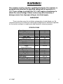
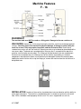
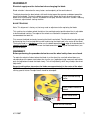
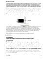
1
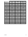
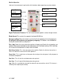
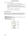
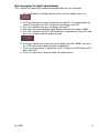
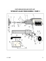
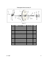
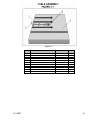
DAKE / JOHNSON VERTICAL BAND SAW
Model F - 16
INSTRUCTION MANUAL
Need band saw blades? Call Dake
MODEL:F-16________________________
SERIAL NUMBER:___________________
DATE PURCHASED: _________________
4/11/2007
DAKE (Division of JSJ)
724 Robbins Road
Grand Haven, Michigan 49417
616.842.7110
Phone
800-937-3253
616.842.0859
Fax
800-846-3253
Web: www.dakecorp.com
E-mail : [email protected]
[email protected]
1
WARNING!
This machine must be wired by a qualified electrician. This machine is
designed to be wired for the specified voltage with a tolerance of +/10%. If your voltage is outside this 10% it will require a transformer to
obtain the correct voltage. Failure to do so may affect warranty, if
damage occurs from improper wiring or electrical supply.
FOREWORD
These instructions cover the installation and operation of vertical band saw. We
recommend that these instructions be retained by the department or individual responsible
for the machine and kept in a readily accessible location for reference purposes.
SPECIFICATIONS
Capacity:
Throat
Work Height
Table:
Work Table
Height from Floor
Table Weight Capacity
Blade:
Width Minimum
Width Maximum
Length
Minimum/Maximum
Wheel Diameter
Band Speed:
Variable Speed
Drive Motor
Height of Machine:
Floor Space:
Shipping Weight:
Machine Weight
4/11/2007
Inches
Inches
16
11
Inches
Inches
Lbs.
26-3/8 x 26-3/8
38
850
Inches
Inches
Inches
1/8
5/8
128/133
Inches
16-1/2
FPM
HP
Inches
Inches
60-550 sfm
2
72
28 x 18
Lbs.
1000
2
Machine Features
F - 16
WARNING!!!
The machine table must NOT be used as a lifting point. Damage to the saw could occur.
UNLOADING: Remove the shrink-wrap covering the machine, careful not to damage painted
surfaces. Carefully inspect the machine for physical damage. If damage is noted, notify the
truck line at once. They may require inspection, and that a claim be filed. Check that all
standard accessories are with the machine. Some accessories may be boxed or placed behind the
rear access door. The band saw is provided with a lifting eye that is screwed into the top of the
machine (see illustration on next page). This lifting eye may be located in the rear compartment.
Particular care should be taken in selecting areas of the machine for handling, as electrical
components and adjustment knobs can be marked up or damaged. Remove the mounting bolts
holding the machine to the skid, using the lifting eye, remove the machine from the skid and set in
designated area.
INSTALLATION: Location of the machine should be taken into consideration with the ability to
move large work pieces. The machine is provided with holes in the base to anchor the unit to the
floor. Shims should be used to properly level the unit. The saw is shipped with an anti-rust
4/11/2007
3
protective coating on machined metal surfaces. These surfaces should be cleaned with the
appropriate solvent and then coated with a light film of oil to prevent rust from forming.
F-16
Foot Print
Below measurement is in inches
.98
23.6
17.7
14.9
3.93
19.0
.39
27.3
Below measurement is in MM
25
600
450
18
380
10
485
25
695
4/11/2007
4
ELECTRICAL:
To wire this machine there is a small box on the back side of the machine, this is where the
machine is wired in (see illustration below).
warning!!!
Power must be locked out before removing any
electrical panel.
WARNING!
This machine must be wired by a qualified electrician.
This machine is designed to be wired for the specified
voltage labeled below with a tolerance of +/- 10%. If your
voltage is outside this 10% it will require a transformer
to obtain the correct voltage. Failure to do so may affect
warranty, if damage occurs from improper wiring or
electrical supply.
4/11/2007
5
To change the machine from 1 phase to 3 phase follow the instructions below.
220 Volt 1 Phase
How to wire for 220 Volt 1 Phase:
1. Connect one lead to L1
2. Connect one lead to L3; this must be the neutral wire.
3. Connect ground wire to ground
220 Volt 3 Phase
How to wire for 220 Volt 3 Phase
1. Connect each wire to L1, L2, L3
2. Connect ground wire to ground
440 Volt 3 Phase
To use 440 volt on this machine a step down transformer is required.
Dake part number 300674
Prior to performing any cutting with the machine, it is recommended that the personal
become familiar with the various controls and accessories.
PRECAUTIONS
•
•
•
•
•
•
•
•
•
•
•
No loose clothing.
Eye protection must be worn.
All guards must be in position.
Table load capacity should be noted and not exceeded.
Extra supports may be required for large material or components.
Irregular shapes and small objects should be secured by means of a clamp or suitable fixture.
Machine and surrounding should be kept free of tools, scrap and foreign objects.
Machine should be locked out before making any adjustments.
Gloves must be used when uncoiling, coiling and installing band saw blades.
Store band saw blades in an area near the machine. This will allow operating personal to use
the proper blade for each operation.
Machine is furnished with electrical door interlocks. These interlocks should periodically be
checked for proper operation.
BLADE INSTALLATION
WARNING!!!
Gloves must be worn when changing the blade.
4/11/2007
6
WARNING!!!
Electrical supply must be locked out when changing the blade.
Blade selection is based on the many factors and complexity of the work to be cut.
The blade placed on the band wheels with teeth facing toward the operator and down toward the
top of the worktable. Tension the blade to remove slack. Rotate the wheels by pushing the jog
button to ensure tracking is correct, and blade will not “pop” off when machine is started. If tracking
is incorrect, adjust before starting machine.
BLADE TRACKING
Note: This alignment is factory set, but may need an adjustment after replacing the blade.
This machine has a bottom wheel that drives the saw blade and a top idle wheel that is adjustable
to facilitate blade tracking. The edges of the wheels are fitted with a composite material to
accommodate the tooth set.
First remove the blade tension by loosening the black hand wheel. The idle wheel may be adjusted
by loosening the silver knurled locking collar and turning the black knob in the center of the wheel.
Turning the knob in a clockwise manner runs the blade toward the back edge of the band wheel. A
counter clockwise movement will move the blade toward the front edge of the band wheel (see
picture on below).
WARNING!!!
Before performing the procedure below be sure the wheel safety doors are closed.
To rotate the wheel to find out where the blade is on the wheel, be sure both wheel doors are
closed and push the power start button then turn the run / jog button to jog, now push and hold or
push the jog button to rotate the blade slowly. This will help identify which way to adjust the wheel
adjustment.
Correct tracking takes place when the blade runs approximately in the center of the wheel.
NOTE: The main casting with adjusting screws have been preset at the factory during assembly
utilizing special fixtures. No adjustment should be attempted.
Silver knurled locking
collar.
Black knob in center of
wheel.
Black hand wheel
Blade tension indicator
4/11/2007
7
BLADE TENSIONING
The blade indicator is located inside the upper wheel compartment, on the lower left side of the idle
wheel. (See picture above) The indicator has an arrow mounted on the horizontal plane, with a
corresponding scale for blade tensioning. The scale has two legends, one reads inches from 0 - 1”,
and the second reads mm 0 - 25 mm. This allows tensioning either standard or metric blade widths.
With out tension on the blade, the indicator should read zero. As tension is applied to the blade the
needle will move accordingly, and should be tightened until the correct blade width is indicated on
this gauge. Example: Installing a 1/2” blade on the machine, tighten the hand wheel until the
indicator’s arrow is pointing to the 1/2” mark on the scale. Before starting the machine, check the
blade tracking by pushing the jog button for one or two seconds.
This indicator has been calibrated at the factory. If recalibration is ever needed follow the steps
below:
Using a blade tension gauge, (many times the company that you purchase blades from can furnish
you with this gauge) tension the blade to the proper PSI. The PSI will very from blade types
(carbon, Bi-metal) and blade widths. This information can be obtained from your blade supplier.
When proper tension is achieved, loosen the setscrew in the collar on the tensioning wheel shaft.
(See figure 6 above) Adjust this collar up or down on the shaft until the arrow is pointing to the
corresponding blade width. On the indicator. Tighten setscrew.
Note: It is better to over tension the blade than to run it under tensioned.
BLADE GUIDES
WARNING!!!
Gloves must be worn when handling or adjusting the blade guides.
WARNING!!!
Electrical supply must be locked out when adjusting or changing blade guides.
Your machine has come equipped with a set of interchangeable “V” type blade guides. A
set of guides consist of two each left hand and two each right hand guide inserts. The
standard guides furnished are 10 / 12 mm guides. Other sizes are optional, and can be
purchased separately, or as a five piece set. The five-piece set includes 3 / 4 mm (1/8 1/4”) 6 / 8 mm (5/16 - 3/8”) 10 / 12 mm (standard set 1/2 - 5/8”) the blade width will dictate the
size blade guide to be used.
Note: Never use blades larger than the rated capacity of the machine. Never use blades
narrower than guide insert. Damage will occur to guide insert and blade. Blade insert must
correspond with blade width.
4/11/2007
8
The blade should always be inspected before installing on the machine. Things to look for should
be the smoothness on the sides and back edge of the weld, look for any missing teeth, or impacted
chips. The blade guides may now be selected and inserted into both the upper and lower guide
holders. Proper adjustment of these guides takes place when they form a complete “V” shape (see
graphic above) and support the blade equally on each side. A couple of thousands on each side of
the blade will provide the running clearance and support for contour sawing.
Note: Chips should be removed from the blade guides during each blade change or
more frequently if required.
BLADE GUIDES
The back end roller that supports the back of the blade on each guide holder contains a hardened
cap over a set of ball bearings. This should be checked periodically for free movement so it is
allowed to rotate freely as the back of the blade comes in contact with the face of this roller.
Noticeable friction in this assembly indicates it should be replaced. This can be done by removing
the right hand guide insert, moving the left hand guide up away from the bearing face. Loosen the
setscrew on the bottom of the guide holder and sliding the old bearing and shaft out and a new one
in. Tighten the setscrew and re-adjust the guides. See graphic below.
The “V” type solid blade guides and holder assemblies as furnished standard with the machine and
are recommended for the majority of cutting applications.
BAND SPEED SELECTION
The saw blade is driven by a direct drive transmission. On the front panel you will see the surface
feet per minute read out (see chart for proper blade selection).
4/11/2007
9
MATERIAL SHAPE
MATERIAL SHAPE
MATERIAL SHAPE
INCHES
TOOTH SELECTION
TOOTH SELECTION
TOOTH SELECTION
0
.1
.2
.3
.4
.5
.6
.7
.8
.9
1
1 1/4
1 1/2
1 3/4
2
2 1/4
2 1/2
2 3/4
3
3 1/4
3 1/2
3 3/4
4
5
6
7
8
9
10
11
14 / 18
14 / 18
14 / 18
10 / 14
8 / 12
8 / 12
6 / 10
6 / 10
5/8
5/8
5/8
4/6
4/6
4/6
4/6
4/6
3/4
3/4
3/4
3/4
3/4
3/4
3/4
2/3
2/3
2/3
1.4 / 2.5
1.4 / 2.5
1.4 / 2.5
1.4 / 2.5
14 / 18
14 / 18
14 / 18
14 / 18
10 / 14
8 / 12
8 / 12
6 / 10
6 / 10
5/8
5/8
5/8
4/6
4/6
4/6
4/6
4/6
4/6
3/4
3/4
3/4
3/4
3/4
3/4
3/4
2/3
2/3
2/3
1.4 / 2.5
1.4 / 2.5
14 / 18
14 / 18
14 / 18
10 / 14
8 / 12
6 / 10
5/8
5/8
5/8
5/8
4/6
4/6
4/6
4/6
3/4
3/4
3/4
3/4
3/4
3/4
3/4
2/3
2/3
2/3
2/3
1.4 / 2.5
1.4 / 2.5
1.4 / 2.5
1.4 / 2.5
1.4 / 2.5
MATERIAL IN
4/11/2007
10
Machine Operation
Look over the control panel to get familiar with the buttons before operating (see picture below).
Digital Tach
read out
Blade Speed
Emergency Stop
Run / Jog
Power Start
Saw Start
Saw Stop
Jog
Main Power
Switch
Digital Tachometer Read out: This will show the blade speed in surface feet per minute.
Blade Speed: This controls the speed of the blade 50-550 sfm.
Emergency Stop: When this button is pushed it will shut all power off to all components.
Do not push this button for non emergency stopping. This button is not intended for
turning the machine off on a daily basis.
Run / Jog: Switch this to run when the machine is being used. Switch this to jog when you
need to slowly move the blade to make adjustments for the blade tracking. After switching
this to jog use the jog button to slowly move the blade.
Main Power Switch: This is the main power to the machine. Switch this off when the machine is
not in use. Switch this to on to turn the main power on.
Power Start : This is used to turn on the power after turning on the main power; it will put power to
all electrical components.
Saw Start : This will start the saw blade motor when pushed.
Saw Stop : This will stop the Saw blade motor when pushed.
Jog : When this is pushed then released the motor will come on and then shut off. This feature is
used only when adjusting the tracking.
4/11/2007
11
MACHINE OPERATION
To operate the machine, do the following:
1. Turn the main power on, and then push the saw power button.
2. Now turn the run jog button to run, and then push the saw start button. The saw
blade will begin to move at the designated speed that is selected.
3. To change the blade speed, turn the blade speed knob to the desired speed by
turning left or right. It will take about 3 seconds for the digital tac to read the correct
speed.
4. To stop the saw blade push the saw blade stop button.
5. To turn the machine off turn the main power switch to off.
MACHINE MAINTENANCE
The maintenance of the machine is naturally based on the usage rather than a time
element. The following is a recommendation based-on-average usage, and adjustment to
the frequency can be made on an individual basis. See below graphic for locations.
•
•
•
•
•
Chip Pan: Clean as required
Band wheel tires: Remove embedded chips weekly, replace banding as necessary.
Blade guide assemblies: Clean weekly
Gear box: Maintenance free
Blade tension assembly: Clean weekly
4/11/2007
12
ACCESSORIES
Rip Fence Part number 81521
PROTRACTOR HEAD
See figure 4 part number 75561
T-SLOTS
T-slots are machined into the work table for your use
of fixturing or other accessories. The dimensions of
these T-slots are furnished to the right.
How to program the frequency drive.
1. Please see the electrical print for the parameter list.
(This is factory set and will only need to be adjusted if the unit is replaced)
4/11/2007
13
How to program the digital speed display
(This is factory set and will only need to be programmed if the unit is replaced)
1. Press and hold the set button (top left corner) until the display shows Fun
2. Push the set button one time, the display will read rPS . If the display does not
show rPS then push the “RST” button until the display shows rPS.
3. Press the set button one time, the display will read “P”.
4. Now, open the cover below the digital display and input the numbers 25400
5. Press the set button then RST until the decimal is between the 4 and the 0, now
press the set button and the display will read
6. Push the set button one more time and the display will read “99999” now, push
the RST button until no decimal points are displayed.
7. Push set one more time, it should read “rd15”. If not push the RST button untill it
does read “rd15”.
8. Push set 4 more times. Now the display will read correctly.
4/11/2007
14
PARTS BREAKDOWN AND PARTS LIST
4/11/2007
15
ITEM
4/11/2007
Figure 1.1
PART NAME
PART NO.
F-16
1
2
3
4
5
6
7
8
9
10
11
12
13
14
15
16
17
18
19
20
21
22
23
24
25
26
27
28
29
30
31
32
33
Hand wheel
Adjusting Wheel Collar
Spindle
Crown Spring
Axial Bearing
Spacer
Lath Gib
Carriage
Carriage Lower Portion
Rack
Screw 4mm x 16mm
Pin
Set Screw 6mm x 10mm 8 pitch
Flat Head Screw 4mm x 6mm
Needle Bearing K20x24x17
Screw 8mm x 20mm
Guide Post
Set Screw 10mm x 20mm
Threaded Sleeve
Plate
Handle Bolt
Roll Pin
Star Handle
Cap Screw 6mm x 12mm
Set Screw 6mm x 10mm 8 pitch
Gear
Roll Pin
Handle
Hand Wheel
Flange
Hand Wheel Adjusting Bolt
Tension Collar Set Screw
Tension Indicator Collar
81529
81530
81532
81534
81536
81538
81540
81542
81544
81546
81548
81549
80529
81551
81552
80521
81555
81560
81558
81561
81563
81654
81565
80625
80529
81566
81568
80501
80500
81569
81570
1
1
1
6
1
1
2
1
1
1
2
1
1
2
1
9
1
1
4
1
1
1
1
3
1
1
1
1
1
1
1
1
1
34
Tension Indicator Pointer Rod
81973
1
35
36
37
38
39
40
Indicator Pointer Return Spring
Indicator Plate
Mounting Bolts
Pivot Bolt
Pivot Bolt Nut
Plate Spacers
V-16 Bracket Assembly
716500
1
1
1
2
1
2
1
16
Tracking band wheel assembly 1.2
Figure 1.2
4/11/2007
ITEM
PART NAME
PART NO.
1
2
3
4
5
6
7
8
9
10
11
12
13
14
15
16
17
18
19
20
Complete Assembly
Screw 8mm x 10mm
Jam nut 8mm
Set Screw 8mm x 25mm
Nylon Bandage (80540)
Upper Band Wheel
Cap Screw 8mm x 25 mm
Flange
Special Pin 88mm x 16mm dia
Set Screw 8mm x 16mm
Adjuster Casting
Shoulder Bolt
Bearing 62042
Snap Ring
Spacer 20.7mm IDx25mm OD 18.5mm
Flat Washer 5/16” x 1/16” Thick
Shaft Nut
Screw (Special)
Nut (Special Knurled)
Adjusting Hand Wheel
Roll Pin
716501
81571
91573
81574
714834
80618
81575
80650
81577
81572
81579
81581
80685
5136-00
81586
43632
81588
81590
81592
81595
81594
1
2
1
1
1
1
4
1
1
1
1
1
2
2
1
4
1
1
1
1
-
17
Figure 2.1
4/11/2007
ITEM
PART NAME
PART NO.
V/E-16
1
2
3
4
5
6
7
8
9
10
11
Table Insert (Left Rear)
Table Insert (Right Rear)
Table Insert
Table Casting
Cap Screw 4mm x 12 mm
Adaptor Plate
Table Bolts M10 1.5 x 25mm
Frame Bolts M10 1.5 x 50mm
Adjustor
Lock washer
Washer
81597
81598
81792
81700
81701
301843
78758
78729
1
1
1
1
10
1
4
4
4
4
4
43642
71060
18
Lower Wheel assembly 3.7
ITEM
PART NAME
1
2
3
4
5
6
Band Wheel Cover – Sold as 714834x
Band Wheel Casting
Set Screw
Flange
Washer 5/16” x 1/16” thick
Cap Screw 8mm x 25mm
Complete Wheel Assembly
Wheel magnet
Proximity switch
Not shown
Not shown
4/11/2007
PART NO. V/E-16
80540
80618
81863
81865
43632
81575
714834X
301834
301833
1
1
1
1
4
4
1
1
1
19
Blade guard assembly 4.6
11
4
3
15
10
3
14
13
12
5
14
17
5
18
18
Blade guard assembly 4.6
4/11/2007
Item
#
3
4
5
10
11
12
13
14
15
15B
17
Part #
Part Description
Qty.
81926
81924
81526
81929
81930
81931
81932
81933
81934
80625
78206
1
2
2
1
1
1
1
2
1
2
1
18
86589
Brush bolt
Wood screw
Knurled thumb screw
Chip guard
Brush holder
Wire chip brush
Upper blade cover
Alignment screws
Blade guard body
Blade guard mounting bolts
Lower blade cover
w/Plexiglas
Side blade guards
2
20
Blade Guide Assembly 4.8
Item #
1
2
3
4/7/8
5
6
9
10
11
12
13/14
15/16
16/17
17/18
19/20
4/11/2007
Part Name
Cap Screw
Blade Guide Holder
Set Screw
Rear Bearing Guide Assembly
Washer
Cap Screw
Cap Screw
Washer
Cap Screw
Lower Guide Mounting Plate
Guide Inserts (Optional) 3mm/4mm
Guide Inserts (Optional) 6mm/8mm
Guide Inserts (Standard) 10mm/12mm
Guide Inserts (Optional) 16mm/20mm
Guide Inserts (Optional) 25mm/32mm
High Speed Roller Guides
Upper & Lower Guide Assembly (Items 1-8)
Part # Qty.
81781
81935
81936
80586
81938
64179
80521
43632
81707
81941
714816
714817
714818
714819
714820
81969
714838A
2
2
2
2
4
4
1
1
2
1
2
2
2
2
2
1 set
1
21
1
2
3
8
4
9
5
10
6
11
7
12
13
14
15
Item #
1
2
3
4
5
6
7
8
9
10
11
12
12
13
14
14
15
4/11/2007
PART NAME
Gear box
Motor Single Phase and 3 phase
Digital read out
Blade Speed Dial
Emergency Stop Button
Run / Jog Switch
Main Power switch w / motor protection
Power Start Button
Saw Start Button
Saw Stop Button
Jog Button
Relay
Relay socket
Contactor
Fuse 2 amp
Transformer and Fuse Holder
Switch
PART
NO.
Qty
301663
301665
301832
301666
716538
716544
301781
716542
716540
716539
716543
301776
301775
301777
77523
301778
301789
1
1
1
1
1
1
1
1
1
1
1
1
1
1
2
1
1
22
Items not shown on gear box assembly
Washer
Bolt
Shaft
Bearing
Outboard Support
8mm x 35mm
8mm x 65mm
Key
Key ¼ x ¼ x 4”
Door Handle
Shaft Extension
Fuse 2 amp
Fuse 5 amp
Frequency drive
4/11/2007
70270
81505
87121
301810
87131
301811
301812
81851
301818
301779
301780
72633
301886
2
2
1
1
1
4
4
1
1
1
2
1
1
23
4/11/2007
24