1
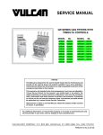
SERVICE MANUAL
GR SERIES GAS FRYERS WITH
MILLIVOLT CONTROLS
MODEL
ML
MODEL
ML
GR25
126988
GR35F
126998
GR35
126989
GR45F
126999
GR45
126990
GR65F
135534
GR65
126991
GR85F
135535
GR85
126992
GR35 SHOWN
- NOTICE This Manual is prepared for the use of trained Vulcan Service
Technicians and should not be used by those not properly
qualified. If you have attended a Vulcan Service School for this
product, you may be qualified to perform all the procedures
described in this manual.
This manual is not intended to be all encompassing. If you have
not attended a Vulcan Service School for this product, you should
read, in its entirety, the repair procedure you wish to perform to
determine if you have the necessary tools, instruments and skills
required to perform the procedure. Procedures for which you do
not have the necessary tools, instruments and skills should be
performed by a trained Vulcan Service Technician.
Reproduction or other use of this Manual, without the express
written consent of Vulcan, is prohibited.
For additional information on Vulcan-Hart Company or to locate an authorized parts
and service provider in your area, visit our website at www.vulcanhart.com.
A product of VULCAN-HART
LOUISVILLE, KY 40201-0696
F25125 (March 2003)
GR SERIES GAS FRYERS
TABLE OF CONTENTS
GENERAL . . . . . . . . . . . . . . . . . . . . . . . . . . . . . . . . . . . . . . . . . . . . . . . . . . . . . . . . . . . . . . . . . . . . . . . . . . . . . . . .
Introduction . . . . . . . . . . . . . . . . . . . . . . . . . . . . . . . . . . . . . . . . . . . . . . . . . . . . . . . . . . . . . . . . . . . . . . . . . . . .
Single Floor Model or Battery Fryers . . . . . . . . . . . . . . . . . . . . . . . . . . . . . . . . . . . . . . . . . . . . . . . . . . . . . . . .
Model Designations . . . . . . . . . . . . . . . . . . . . . . . . . . . . . . . . . . . . . . . . . . . . . . . . . . . . . . . . . . . . . . . . .
Models and Features . . . . . . . . . . . . . . . . . . . . . . . . . . . . . . . . . . . . . . . . . . . . . . . . . . . . . . . . . . . . . . . .
Kleenscreen Filtering System . . . . . . . . . . . . . . . . . . . . . . . . . . . . . . . . . . . . . . . . . . . . . . . . . . . . . . . . . . . . . .
Model Designations . . . . . . . . . . . . . . . . . . . . . . . . . . . . . . . . . . . . . . . . . . . . . . . . . . . . . . . . . . . . . . . . .
Models and Features . . . . . . . . . . . . . . . . . . . . . . . . . . . . . . . . . . . . . . . . . . . . . . . . . . . . . . . . . . . . . . . .
Specifications . . . . . . . . . . . . . . . . . . . . . . . . . . . . . . . . . . . . . . . . . . . . . . . . . . . . . . . . . . . . . . . . . . . . . . . . . .
Electrical . . . . . . . . . . . . . . . . . . . . . . . . . . . . . . . . . . . . . . . . . . . . . . . . . . . . . . . . . . . . . . . . . . . . . . . . . .
Gas Pressures . . . . . . . . . . . . . . . . . . . . . . . . . . . . . . . . . . . . . . . . . . . . . . . . . . . . . . . . . . . . . . . . . . . . .
Input BTU Rating . . . . . . . . . . . . . . . . . . . . . . . . . . . . . . . . . . . . . . . . . . . . . . . . . . . . . . . . . . . . . . . . . . .
Tools . . . . . . . . . . . . . . . . . . . . . . . . . . . . . . . . . . . . . . . . . . . . . . . . . . . . . . . . . . . . . . . . . . . . . . . . . . . . . . . . .
3
3
3
3
3
4
4
4
5
5
5
5
5
REMOVAL AND REPLACEMENT OF PARTS . . . . . . . . . . . . . . . . . . . . . . . . . . . . . . . . . . . . . . . . . . . . . . . . . . . . 5
Front Panel . . . . . . . . . . . . . . . . . . . . . . . . . . . . . . . . . . . . . . . . . . . . . . . . . . . . . . . . . . . . . . . . . . . . . . . . . . . . 5
Door . . . . . . . . . . . . . . . . . . . . . . . . . . . . . . . . . . . . . . . . . . . . . . . . . . . . . . . . . . . . . . . . . . . . . . . . . . . . . . . . . 5
Control Thermostat . . . . . . . . . . . . . . . . . . . . . . . . . . . . . . . . . . . . . . . . . . . . . . . . . . . . . . . . . . . . . . . . . . . . . . 6
High Limit Thermostat . . . . . . . . . . . . . . . . . . . . . . . . . . . . . . . . . . . . . . . . . . . . . . . . . . . . . . . . . . . . . . . . . . . 6
Main Burners . . . . . . . . . . . . . . . . . . . . . . . . . . . . . . . . . . . . . . . . . . . . . . . . . . . . . . . . . . . . . . . . . . . . . . . . . . 7
Main Burner Orifice . . . . . . . . . . . . . . . . . . . . . . . . . . . . . . . . . . . . . . . . . . . . . . . . . . . . . . . . . . . . . . . . . . . . . . 8
Gas Combination Valve . . . . . . . . . . . . . . . . . . . . . . . . . . . . . . . . . . . . . . . . . . . . . . . . . . . . . . . . . . . . . . . . . . 8
Pilot Burner . . . . . . . . . . . . . . . . . . . . . . . . . . . . . . . . . . . . . . . . . . . . . . . . . . . . . . . . . . . . . . . . . . . . . . . . . . . . 9
Thermopile . . . . . . . . . . . . . . . . . . . . . . . . . . . . . . . . . . . . . . . . . . . . . . . . . . . . . . . . . . . . . . . . . . . . . . . . . . . . 9
Fry Tank Assembly . . . . . . . . . . . . . . . . . . . . . . . . . . . . . . . . . . . . . . . . . . . . . . . . . . . . . . . . . . . . . . . . . . . . . 10
Filter Valve and Discard Valve Switches . . . . . . . . . . . . . . . . . . . . . . . . . . . . . . . . . . . . . . . . . . . . . . . . . . . . 11
Pump and Motor . . . . . . . . . . . . . . . . . . . . . . . . . . . . . . . . . . . . . . . . . . . . . . . . . . . . . . . . . . . . . . . . . . . . . . . 11
SERVICE PROCEDURES AND ADJUSTMENTS . . . . . . . . . . . . . . . . . . . . . . . . . . . . . . . . . . . . . . . . . . . . . . . . .
Control Thermostat Calibration . . . . . . . . . . . . . . . . . . . . . . . . . . . . . . . . . . . . . . . . . . . . . . . . . . . . . . . . . . . .
Gas Manifold Pressure Adjustment . . . . . . . . . . . . . . . . . . . . . . . . . . . . . . . . . . . . . . . . . . . . . . . . . . . . . . . .
Pilot Burner Flame Adjustment . . . . . . . . . . . . . . . . . . . . . . . . . . . . . . . . . . . . . . . . . . . . . . . . . . . . . . . . . . . .
Millivolt Controls Test . . . . . . . . . . . . . . . . . . . . . . . . . . . . . . . . . . . . . . . . . . . . . . . . . . . . . . . . . . . . . . . . . . .
12
12
13
13
14
ELECTRICAL OPERATION . . . . . . . . . . . . . . . . . . . . . . . . . . . . . . . . . . . . . . . . . . . . . . . . . . . . . . . . . . . . . . . . . .
Component Function . . . . . . . . . . . . . . . . . . . . . . . . . . . . . . . . . . . . . . . . . . . . . . . . . . . . . . . . . . . . . . . . . . .
Component Location . . . . . . . . . . . . . . . . . . . . . . . . . . . . . . . . . . . . . . . . . . . . . . . . . . . . . . . . . . . . . . . . . . .
Sequence of Operation . . . . . . . . . . . . . . . . . . . . . . . . . . . . . . . . . . . . . . . . . . . . . . . . . . . . . . . . . . . . . . . . . .
Millivolt Controls . . . . . . . . . . . . . . . . . . . . . . . . . . . . . . . . . . . . . . . . . . . . . . . . . . . . . . . . . . . . . . . . . . .
Kleenscreen Filtering System . . . . . . . . . . . . . . . . . . . . . . . . . . . . . . . . . . . . . . . . . . . . . . . . . . . . . . . . .
Schematic Diagram . . . . . . . . . . . . . . . . . . . . . . . . . . . . . . . . . . . . . . . . . . . . . . . . . . . . . . . . . . . . . . . . . . . .
Millivolt Controls . . . . . . . . . . . . . . . . . . . . . . . . . . . . . . . . . . . . . . . . . . . . . . . . . . . . . . . . . . . . . . . . . . .
Wiring Diagrams . . . . . . . . . . . . . . . . . . . . . . . . . . . . . . . . . . . . . . . . . . . . . . . . . . . . . . . . . . . . . . . . . . . . . . .
Millivolt Controls . . . . . . . . . . . . . . . . . . . . . . . . . . . . . . . . . . . . . . . . . . . . . . . . . . . . . . . . . . . . . . . . . . .
Junction Box, Kleenscreen Filtering System . . . . . . . . . . . . . . . . . . . . . . . . . . . . . . . . . . . . . . . . . . . . .
Frymate (Dump Station) . . . . . . . . . . . . . . . . . . . . . . . . . . . . . . . . . . . . . . . . . . . . . . . . . . . . . . . . . . . . .
15
15
16
17
17
17
18
18
19
19
20
21
TROUBLESHOOTING . . . . . . . . . . . . . . . . . . . . . . . . . . . . . . . . . . . . . . . . . . . . . . . . . . . . . . . . . . . . . . . . . . . . . .
All Models . . . . . . . . . . . . . . . . . . . . . . . . . . . . . . . . . . . . . . . . . . . . . . . . . . . . . . . . . . . . . . . . . . . . . . . . . . . .
Frymate (Dump Station) with Optional Heater . . . . . . . . . . . . . . . . . . . . . . . . . . . . . . . . . . . . . . . . . . . . . . . .
Kleenscreen Filtering System . . . . . . . . . . . . . . . . . . . . . . . . . . . . . . . . . . . . . . . . . . . . . . . . . . . . . . . . . . . . .
22
22
23
23
CONDENSED SPARE PARTS LIST . . . . . . . . . . . . . . . . . . . . . . . . . . . . . . . . . . . . . . . . . . . . . . . . . . . . . . . . . . . 24
© VULCAN 2003
F25125 (March 2003)
Page 2 of 24
GR SERIES GAS FRYERS - GENERAL
GENERAL
INTRODUCTION
This Service Manual covers specific service information related to the models listed on the front cover.
SINGLE FLOOR MODEL OR
BATTERY FRYERS
Fryers with the Filter-Ready option installed, use the Mobile Filter. For service information related to the Mobile
Filter, refer to F24599 MOBILE FILTERS. Filter-Ready fryers are available as single floor models only.
The information in the GR Series Service Manual also applies to Non-Filter Ready fryers. Non-Filter Ready fryers
are available in batteries of two to six.
An RO Frymate (dump station) can be configured in a battery with fryers 15 1/2" or 21" in width.
Model Designations
Models and Features
FEATURES
MODEL
FRYER
WIDTH
(INCHES)
SHORTENING
CAPACITY
(POUNDS)
FRY
TANK
COOKING
CONTROL
GR25 1
10 1/2
25-30
Full
Thermostat
GR35
15 1/2
35-40
Full
Thermostat
GR45
15 1/2
45-50
Full
Thermostat
GR65
21
65-70
Full
Thermostat
GR85
21
85-90
Full
Thermostat
RO15
(Frymate)
15 1/2
RO21
(Frymate)
21
RO21S
(Frymate)
21
NOTE:
1. Available in battery configurations only.
Page 3 of 24
F25125 (March 2003)
GR SERIES GAS FRYERS - GENERAL
KLEENSCREEN FILTERING
SYSTEM
The Kleenscreen fryer battery still utilizes many of
the same components as the single floor model and
Non-Filter ready battery fryers.
The new Kleenscreen filtering system has been
integrated into the GR Series fryer battery. The filter
is housed in a pull-out drawer assembly at the base
of the fryer. The filtering components in the drawer
include a stainless steel filter tank, crumb-catch
basket and a dual element mesh filter screen. With
the filter drawer closed, a self-seating oil return line
provides the path to return the filtered oil to the fry
tank.
Kleenscreen fryer batteries are available in a
minimum of two and a maximum of six fryer
sections. The fryer size of each section is identical.
An RO Frymate (dump station) can also be included
as one or more of the sections.
Model Designations
This system is designed to provide a thorough and
easy method for filtering shortening.
Some of the benefits include:
•
Self-contained system eliminating the use of
external filter equipment.
•
Paperless filtering system.
•
Easy to clean and low maintenance.
Models and Features
FEATURES
MODEL
FRYER
WIDTH
(INCHES)
SHORTENING
CAPACITY
PER FRYER
(POUNDS)
KLEENSCREEN FILTER
PAN CAPACITY
(POUNDS)
FRY
TANK
COOKING
CONTROL
2GR35F 1
31
35-40
80
Full
Thermostat
2GR45F 1
31
45-50
80
Full
Thermostat
2GR65F 2
42
65-70
130
Full
Thermostat
2GR85F 2
42
85-90
130
Full
Thermostat
RO15
(Frymate)
15 1/2
RO21
(Frymate)
21
RO21S
(Frymate)
21
NOTES:
1. For each additional fryer section, add 15 1/2" to the width.
2. For each additional fryer section, add 21" to the width.
F25125 (March 2003)
Page 4 of 24
GR SERIES GAS FRYERS - REMOVAL AND REPLACEMENT OF PARTS
Input BTU Rating
SPECIFICATIONS
GR SERIES
Electrical
•
120VAC supply for Filter-Ready fryers and
Kleenscreen filter models only. The filter pump
motor draws approximately 5 amps.
NO. OF
BTU/HR/SECTION
TUBES
GR25, GR25F
2
60,000
GR35, GR35F
3
90,000
Gas Pressures
GR45, GR45F
4
120,000
Manifold (per fryer section):
GR65, GR65F
5
150,000
•
Natural - 4" W.C.
GR85, GR85F
5
150,000
•
Propane - 10" W.C.
Building supply pressure (Min):
•
Natural - 5" W.C. (7" W.C. battery units)
•
Propane - 11" W.C. (12" W.C. battery units)
TOOLS
Standard
NOTE: Propane or Natural gases -14" W.C. (Max).
•
•
•
•
•
Standard set of hand tools.
VOM with AC current tester.
NOTE: Any quality VOM with a sensitivity of
20,000 ohms per volt can be used.
Temperature tester (thermocouple type).
U-Tube Manometer.
Pipe joint compound suitable for use with
propane gas.
REMOVAL AND REPLACEMENT OF PARTS
FRONT PANEL
DOOR
WARNING: DISCONNECT THE
ELECTRICAL POWER TO THE
MACHINE AND FOLLOW LOCKOUT /
TAGOUT PROCEDURES.
1.
Open fryer door and remove screws from front
panel.
2.
Lift front panel from fryer.
3.
Reverse procedure to install.
1.
Page 5 of 24
Open the fryer door and remove screws
securing hinge & door assembly to fryer.
F25125 (March 2003)
GR SERIES GAS FRYERS - REMOVAL AND REPLACEMENT OF PARTS
2.
When replacing door, install screws and tighten
top and bottom screws enough to hold door in
place.
3.
Close door, check alignment and adjust if
necessary.
4.
Finish tightening screws to fully secure.
6.
Remove screws securing capillary tube
mounting clips to the fry tank heat tube then
remove capillary tube.
7.
Reverse procedure to install and check for
proper operation.
CONTROL THERMOSTAT
WARNING: DISCONNECT THE
ELECTRICAL POWER TO THE
MACHINE AND FOLLOW LOCKOUT /
TAGOUT PROCEDURES.
CAUTION: Do not sharply bend and kink the
capillary tube or damage may occur.
1.
Drain shortening from fry tank.
2.
Remove burners (as necessary) as outlined
under MAIN BURNERS.
3.
Remove knob from control thermostat shaft
then remove control thermostat from mounting
bracket.
HIGH LIMIT THERMOSTAT
WARNING: DISCONNECT THE
ELECTRICAL POWER TO THE
MACHINE AND FOLLOW LOCKOUT /
TAGOUT PROCEDURES.
CAUTION: Do not sharply bend and kink the
capillary tube or damage may occur.
1.
Drain shortening from fry tank.
2.
Remove burners (as necessary) as outlined
under MAIN BURNERS.
3.
Remove screws securing the high limit
thermostat to mounting bracket.
4.
Disconnect lead wires from high limit
thermostat.
NON FILTER READY SHOWN
4.
Disconnect lead wires from control thermostat.
5.
Remove the capillary tube retaining and packing
nuts, from the bottom of fry tank.
F25125 (March 2003)
Page 6 of 24
GR SERIES GAS FRYERS - REMOVAL AND REPLACEMENT OF PARTS
5.
Remove the capillary tube retaining and packing
nuts, from the bottom of fry tank.
6.
Remove screws securing capillary tube
mounting clips to the fry tank heat tube then
remove capillary tube.
3.
Lift main burner up and tilt the top of burner
toward fry tank until it clears the gas orifice at
the bottom.
A.
7.
Lift main burner from fryer.
Reverse procedure to install.
MAIN BURNERS
WARNING: DISCONNECT THE
ELECTRICAL POWER TO THE
MACHINE AND FOLLOW LOCKOUT /
TAGOUT PROCEDURES.
WARNING: SHUT OFF THE GAS BEFORE
SERVICING THE UNIT.
1.
Open fryer door.
2.
Remove main burner shipping ties (if installed).
NOTE: All shipping ties should be removed during
installation. Do not replace for normal operation.
NOTE: The main burners mount to the fryers’ burner
mounting bracket by shoulder bolts that rest in the
keyway slot.
Page 7 of 24
F25125 (March 2003)
GR SERIES GAS FRYERS - REMOVAL AND REPLACEMENT OF PARTS
GAS COMBINATION VALVE
WARNING: DISCONNECT THE
ELECTRICAL POWER TO THE
MACHINE AND FOLLOW LOCKOUT /
TAGOUT PROCEDURES.
WARNING: SHUT OFF THE GAS BEFORE
SERVICING THE UNIT.
WARNING: ALL GAS JOINTS DISTURBED
DURING SERVICING MUST BE CHECKED FOR
LEAKS. CHECK WITH A SOAP AND WATER
SOLUTION (BUBBLES). DO NOT USE AN OPEN
FLAME.
NOTE: Gas combination valves are not serviceable
and should not be disassembled. Once the problem
has been isolated to this control, replace it. Do not
attempt to repair the assembly.
4.
1.
Remove burners (as necessary) as outlined
under MAIN BURNERS.
2.
Disconnect lead wires from gas combination
valve.
3.
On filter ready and Kleenscreen fryers only,
remove cotter pin securing handle to gas
combination valve on/off knob. Pull handle (with
gas combination valve knob bracket attached)
away from valve assembly.
4.
Disconnect pilot tube.
5.
Separate gas line fittings then remove gas
combination valve assembly.
Reverse procedure to install.
MAIN BURNER ORIFICE
WARNING: DISCONNECT THE
ELECTRICAL POWER TO THE
MACHINE AND FOLLOW LOCKOUT /
TAGOUT PROCEDURES.
WARNING: SHUT OFF THE GAS BEFORE
SERVICING THE UNIT.
1.
Remove main burner orifice from orifice
extension.
NOTE: When installing, do not over tighten the
orifice or damage to the threads may occur.
NON FILTER READY SHOWN
2.
Reverse procedure to install.
F25125 (March 2003)
NOTE: Remove fittings and piping from gas
combination valve and install (in same orientation)
on the replacement valve.
Page 8 of 24
GR SERIES GAS FRYERS - REMOVAL AND REPLACEMENT OF PARTS
6.
Reverse procedure to install and check for
proper operation.
PILOT BURNER
WARNING: DISCONNECT THE
ELECTRICAL POWER TO THE
MACHINE AND FOLLOW LOCKOUT /
TAGOUT PROCEDURES.
WARNING: SHUT OFF THE GAS BEFORE
SERVICING THE UNIT.
WARNING: ALL GAS JOINTS DISTURBED
DURING SERVICING MUST BE CHECKED FOR
LEAKS. CHECK WITH A SOAP AND WATER
SOLUTION (BUBBLES). DO NOT USE AN OPEN
FLAME.
1.
2.
Remove burners (as necessary) as outlined
under MAIN BURNERS.
6.
Disconnect thermopile lead wires from N.O. and
COM terminals on the high limit thermostat.
Reverse procedure to install and check for
proper operation.
THERMOPILE
WARNING: DISCONNECT THE
ELECTRICAL POWER TO THE
MACHINE AND FOLLOW LOCKOUT /
TAGOUT PROCEDURES.
WARNING: SHUT OFF THE GAS BEFORE
SERVICING THE UNIT.
WARNING: ALL GAS JOINTS DISTURBED
DURING SERVICING MUST BE CHECKED FOR
LEAKS. CHECK WITH A SOAP AND WATER
SOLUTION (BUBBLES). DO NOT USE AN OPEN
FLAME.
3.
Disconnect pilot tube from pilot burner.
1.
Remove pilot burner as outlined under PILOT
BURNER.
2.
Remove mounting nut securing thermopile to
pilot burner.
NOTE: With pilot tube disconnected from pilot
burner, the pilot orifice is accessible for inspection or
cleaning.
CAUTION: If orifice is clogged with debris, clean
with air or liquid only.
4.
Remove pilot burner from pilot mounting
bracket stool (on fry tank).
5.
Remove pilot burner from pilot mounting
bracket.
Page 9 of 24
F25125 (March 2003)
GR SERIES GAS FRYERS - REMOVAL AND REPLACEMENT OF PARTS
8.
Remove pilot burner as outlined under PILOT
BURNER.
9.
Remove control thermostat as outlined under
CONTROL THERMOSTAT.
10. Remove high limit thermostat as outlined under
HIGH LIMIT THERMOSTAT.
11. Remove gas manifold and hanger assembly
from the fryer.
3.
Reverse procedure to install and check for
proper operation.
WARNING: DISCONNECT THE
ELECTRICAL POWER TO THE
MACHINE AND FOLLOW LOCKOUT /
TAGOUT PROCEDURES.
WARNING: SHUT OFF THE GAS BEFORE
SERVICING THE UNIT.
WARNING: ALL GAS JOINTS DISTURBED
DURING SERVICING MUST BE CHECKED FOR
LEAKS. CHECK WITH A SOAP AND WATER
SOLUTION (BUBBLES). DO NOT USE AN OPEN
FLAME.
1.
Drain shortening from fry tank.
2.
Disconnect the gas supply line to allow access
to fryer from all sides.
3.
Remove fry baskets, crumb screen and basket
hanger.
NOTE: If the fryer is a battery section, remove
grease strip and split the silicone seal between the
fryer section tanks with a utility knife.
4.
Remove front panel as outlined under FRONT
PANEL.
5.
On Kleenscreen fryer sections only, remove
bolts securing the drain pipe flange to the
manual drain valve.
7.
Remove main burners as outlined under MAIN
BURNERS.
Disconnect lead wires and pilot tube from the
gas combination valve.
F25125 (March 2003)
For fryer sections above the filter drawer
assembly on battery fryers or single floor
model fryers (filter ready), remove
mounting nuts securing gas manifold and
hanger assembly to the fryer’s base frame.
B.
For other fryer sections in a battery and for
non-filter ready fryers, remove mounting
nuts securing gas manifold and hanger
assembly to the V shaped support bracket.
12. On Kleenscreen and filter ready fryers only,
separate the oil return line (hose or flexible
tubing) fitting at the elbow.
FRY TANK ASSEMBLY
6.
A.
13. Separate gas line fitting at the inlet side of the
gas combination valve.
14. Remove bolts securing gas line support bracket
at the left side of gas manifold and hanger
assembly. Allow gas line support bracket to
swing out of way then replace bolts in the
frame. Hand tighten only.
15. Remove screws securing the top of fry tank to
the flue wrap.
CAUTION: Use care when lifting fry tank
assemblies from the fryer body. Exterior
surfaces of the fryer can be slippery and the
assemblies are heavy.
16. Grasp the fry tank at the top (by flue) and front
lip, then lift fry tank assembly from the fryer
body. Place the assembly on floor or table for
removal of the remaining components.
NOTE: If side access is not available, lift fry tank
assembly from the front of the fryer while rotating
the assembly upwards and toward the front.
17. On Kleenscreen fryers only, remove filter valve
assembly (as necessary) and oil return line
piping from fryer. If removing left side fry tank
above filter drawer assembly, disconnect oil
line and remove discard valve assembly from
fryer.
18. Remove bolts securing gas manifold hanger
assembly to the fry tank.
19. Remove screws securing flue box to fry tank
then remove flue box.
20. Remove drain valve.
Page 10 of 24
GR SERIES GAS FRYERS - REMOVAL AND REPLACEMENT OF PARTS
21. Reverse procedure to install all the parts
removed from original fry tank onto
replacement fry tank, then install the assembly.
FILTER VALVE AND DISCARD
VALVE SWITCHES
WARNING: DISCONNECT THE
ELECTRICAL POWER TO THE
MACHINE AND FOLLOW LOCKOUT /
TAGOUT PROCEDURES.
1.
Open the door to the fryer section being
serviced.
2.
Remove burners (as necessary) as outlined
under MAIN BURNERS.
3.
4.
NOTE: The remaining steps are written for front
removal of the pump assembly. If access to the back
of the fryer is available, it may be easier to remove
the pump from the rear.
3.
Remove burners from the right side fryer
section above filter tank drawer as outlined
under MAIN BURNERS.
4.
Disconnect the electrical connection to the
motor.
5.
Separate the swivel hose connections at the
pump.
NOTE: When viewed from pump end, the right side
is the intake port and the left side is the discharge
port.
6.
Remove motor mounting bolts.
7.
Remove the motor and pump (pipe fittings
attached) from the fryer.
Disconnect lead wire connector (2 pin) from the
appropriate switch.
A.
Remove switch mounting screws.
8.
If replacing the pump and motor, remove
the existing pipe assemblies and reuse.
Reverse procedure to install.
NOTE: Ensure the rubber vibration pad or the
grommets are installed under the motor mounting
plate.
5.
Reverse procedure to install and check for
proper operation.
NOTE: Switches are not adjustable.
PUMP AND MOTOR
WARNING: DISCONNECT THE
ELECTRICAL POWER TO THE
MACHINE AND FOLLOW LOCKOUT /
TAGOUT PROCEDURES.
1.
Open both fryer cabinet doors above the filter
tank drawer.
2.
Pull the filter drawer out, remove the filter tank
assembly and push the tank support arms back
underneath the fryer.
Page 11 of 24
F25125 (March 2003)
GR SERIES GAS FRYERS - SERVICE PROCEDURES AND ADJUSTMENTS
SERVICE PROCEDURES AND ADJUSTMENTS
WARNING: CERTAIN PROCEDURES IN THIS SECTION REQUIRE ELECTRICAL TEST OR
MEASUREMENTS WHILE POWER IS APPLIED TO THE MACHINE. EXERCISE EXTREME CAUTION AT ALL
TIMES. IF TEST POINTS ARE NOT EASILY ACCESSIBLE, DISCONNECT POWER AND FOLLOW LOCKOUT
/ TAGOUT PROCEDURES, ATTACH TEST EQUIPMENT AND REAPPLY POWER TO TEST.
CONTROL THERMOSTAT
CALIBRATION
NOTE: Check the level of shortening in fry tank
before proceeding. When the oil temperature is
within normal operating range (325/F - 375/F), the
level must be between the MIN & MAX fill lines.
1.
Place a thermocouple in the geometric center
of the fry tank 1" below the oil surface.
2.
Set control thermostat to 350°F.
3.
Allow the shortening temperature to stabilize
(normally 3 cycles).
4.
Record the temperature reading from the
meter, at which the main burners turn off and
turn on for at least two complete heating
cycles.
5.
Calculate the differential temperature by
subtracting the temperature reading when the
main burners turn off to the temperature
reading when the main burners turn on.
7.
A.
If the average temperature reading is
within tolerance, the control thermostat is
properly calibrated.
B.
If the average temperature reading is out
of tolerance, continue with procedure.
To adjust:
A.
Remove control thermostat knob.
B.
Hold control thermostat shaft and turn the
inner set screw clockwise to decrease
temperature or counterclockwise to
increase temperature (1/4 turn = 18/F).
C.
[ Differential = Temp. (burners off) - Temp. (burners on) ]
Example: 360/ (burners off) - 340/ (burners on) = 20/F.
The differential calculated should be less than
20/F.
6.
A.
If the differential is less than 20/F, the
control thermostat is functioning properly.
B.
If the differential is more than 20/F, the
control thermostat is malfunctioning.
Replace control thermostat knob and
repeat step 6 for up to three attempts.
Allow the main burners to cycle at least two
times between adjustments before
performing the calculation.
1)
Install a replacement control
thermostat as outlined under
CONTROL THERMOSTAT in
REMOVAL AND REPLACEMENT OF
PARTS.
1)
When calibration is successful,
remove control thermostat knob and
apply a non-permanent adhesive
material to set screw head to secure
from rotation.
Calculate the average temperature by adding
the temperature reading when the main burners
turn off to the temperature reading when the
main burners turn on and divide this answer by
2.
2)
Replace control thermostat knob.
8.
[ Temp. (burners off) + Temp. (burners on) ] ÷ 2 =
Average Temp.
Example: 360/ + 340/ ÷ 2 = 350/F.
The average temperature should be
350°F (± 10°F).
F25125 (March 2003)
Page 12 of 24
If the above adjustment cannot be obtained,
install a replacement control thermostat as
outlined under CONTROL THERMOSTAT in
REMOVAL AND REPLACEMENT OF PARTS.
GR SERIES GAS FRYERS - SERVICE PROCEDURES AND ADJUSTMENTS
GAS MANIFOLD PRESSURE
ADJUSTMENT
WARNING: SHUT OFF THE GAS SUPPLY
BEFORE SERVICING THE UNIT.
GAS PRESSURE (INCHES W.C.)
GAS
TYPE
MANIFOLD
LINE
RECOMMENDED MIN MAX
Natural
4
7
5
Propane
10
11
11
14
NOTE: If the incoming line pressure is less than the
minimum stated, then the manifold pressure cannot
be set correctly.
1.
Open the door and turn gas combination valve
knob/extension arm to off.
2.
Remove the 1/8" NPT plug (pressure tap) on
the outlet side of the valve and attach a
manometer.
NOTE: Gas manifold pressure can also be
measured at the pressure tap in the manifold. On
Kleenscreen battery fryers only, the drain pipe may
need to be removed for access.
3.
Turn the gas supply on.
4.
Light the pilot burner and turn the gas
combination valve knob/extension arm to on.
5.
Set control thermostat to call for heat and verify
the main burners light.
6.
Observe the manometer pressure reading and
compare to the pressure chart near the end of
this procedure.
A.
B.
7.
If other appliances are connected to the
same gas line, turn them all on and check
manometer pressure reading again. If a
pressure drop of 1/2" water column or
more is observed, then the gas supply
needs to be checked by the gas line
installer or the local gas company for
adequate sizing.
NON FILTER READY SHOWN
A.
To increase pressure, turn the screw
clockwise. To decrease pressure, turn the
screw counterclockwise.
NOTE: Accurate gas pressure adjustments can only
be made with the gas on and the main burners lit.
8.
Set pressure as outlined in gas pressure table.
9.
Once the correct pressure has been set, turn
the gas combination valve knob/extension arm
to off and shut off the gas supply.
10. Replace the adjustment screw cap and 1/8"
NPT plug (pressure tap) on the outlet side of
the valve.
11. Check fryer for proper operation.
PILOT BURNER FLAME
ADJUSTMENT
NOTE: Verify the proper gas type (natural or
propane) is being supplied to the fryer before
proceeding.
1.
Turn control thermostat to off.
2.
Light pilot burner and leave gas combination
valve knob/extension arm in the pilot position.
Allow pilot to burn for 3-4 minutes to stabilize
flame.
If adjustment is necessary, continue with
procedure.
A.
Remove the adjustment screw cap to access
the pressure adjustment screw.
3.
Page 13 of 24
If pilot burner is not lighting or does not
remain lit when the gas combination valve
knob/extension arm is released, see
TROUBLESHOOTING. Wait 5 minutes
between pilot burner lighting attempts for
unburned gas to vent.
Verify the inner cone of pilot burner flame is
extending approximately 1/2" beyond the outer
edges of the pilot shield.
F25125 (March 2003)
GR SERIES GAS FRYERS - SERVICE PROCEDURES AND ADJUSTMENTS
A.
If adjustment is necessary, continue with
procedure.
MILLIVOLT CONTROLS TEST
1.
Verify millivolt control circuit wiring is correct
and connections are clean and secure.
2.
Verify pilot burner flame is adjusted properly as
outlined under PILOT BURNER FLAME
ADJUSTMENT.
3.
With control thermostat off and gas
combination valve knob/extension arm in the
pilot position, allow pilot to burn for 3-4 minutes
to stabilize voltage output from thermopile.
4.
Verify thermopile output voltage.
A.
4.
Remove the adjustment screw cap from the
gas combination valve.
5.
To increase pilot flame, turn the screw
counterclockwise. To decrease pilot flame,
turn the screw clockwise.
2)
If less than 450 millivolts is
measured, install a replacement
thermopile as outlined under
THERMOPILE in REMOVAL AND
REPLACEMENT OF PARTS.
6.
Verify main burners light and remain lit.
7.
If main burners do not light or pilot burner
goes out, proceed to MILLIVOLT
CONTROLS TEST.
F25125 (March 2003)
If 450 millivolts or greater is
measured, the thermopile is
functioning properly. Continue with
test.
Turn gas combination valve knob/extension
arm to on and set the control thermostat to call
for heat.
With the pilot burner lit, turn gas combination
valve knob/extension arm to on and set the
control thermostat to call for heat.
A.
1)
5.
NON FILTER READY SHOWN
A.
Set VOM to DC millivolt scale and connect
meter leads to N.O. and COM terminals
on the high limit thermostat.
Page 14 of 24
A.
If main burners operate as described, the
millivolt controls are functioning properly.
B.
If main burners do not light, continue with
test.
Verify control thermostat contacts are closing.
A.
Connect meter leads to the TH terminal on
gas combination valve and COM terminal
on the high limit thermostat.
1)
If 150 millivolts or greater is
measured, control thermostat is
functioning properly. Replace gas
combination valve as outlined under
GAS COMBINATION VALVE in
REMOVAL AND REPLACEMENT OF
PARTS.
GR SERIES GAS FRYERS - ELECTRICAL OPERATION
ELECTRICAL OPERATION
COMPONENT FUNCTION
FRYER CONTROLS
Control Thermostat . . . . . . . . . . .
Regulates shortening temperature at the selected set point. Temperature
range from off to 200/F thru 400/F.
Thermopile . . . . . . . . . . . . . . . . . .
When heated by the pilot burner flame, generates DC millivolts to
energize pilot valve coil and main valve coil on the gas combination valve.
Gas Combination
Valve . . . . . . . . . . . . . . . . . . . . . . .
High Limit Thermostat . . . . . . . . .
Allows gas flow to the pilot when pilot valve coil is energized; and gas flow
to the main burners when main valve coil is energized. Also, regulates the
gas manifold pressure.
Prevents the shortening from reaching temperatures over 465°F (auto
reset).
KLEENSCREEN FILTER CONTROLS
Filter Power Switch . . . . . . . . . . .
Supplies 120VAC to pump motor. Filter valve switch or discard valve
switch must be closed (valve handle extended).
Pump Motor . . . . . . . . . . . . . . . . .
Operates pump to circulate shortening through filtering system.
Filter Valve Switch . . . . . . . . . . . .
Energizes pump motor to filter the shortening when the N.O. switch
contacts are closed (valve handle extended); and filter power switch is
turned on.
Discard Valve Switch . . . . . . . . . .
Energizes pump motor to discard the shortening from filter tank when the
N.O. switch contacts are closed (valve handle extended); and filter power
switch is turned on.
Page 15 of 24
F25125 (March 2003)
GR SERIES GAS FRYERS - ELECTRICAL OPERATION
COMPONENT LOCATION
GR35 NON FILTER READY SHOWN
GR45 FILTER READY SHOWN
2GR45F KLEENSCREEN FRYER BATTERY SHOWN
F25125 (March 2003)
Page 16 of 24
GR SERIES GAS FRYERS - ELECTRICAL OPERATION
1.
SEQUENCE OF OPERATION
Conditions
A.
Fryer connected to correct supply voltage
and is properly grounded.
Refer to schematic diagram 7825.
B.
Shortening between 300/F and 350/F.
1.
NOTE: Oil should not be filtered outside of this
temperature range. At lower temperatures the
oil is thicker which may increase filtering time
and place a greater load on the pump. At
higher oil temperatures, oil seal life is
decreased.
Millivolt Controls
Conditions.
A.
Gas shutoff valve(s) on and gas
combination valve knob/extension arm in
the on position.
B.
Shortening at proper level in fry tank and
below last set point temperature used.
C.
Pilot lit.
1)
C.
NOTE: Control thermostat must remain off
during filtering.
Pilot valve coil is energized on gas
combination valve and pilot valve
opens for gas flow to pilot burner.
NOTE: Pilot flame must be sufficient to
generate 450 millivolts DC (minimum)
from thermopile.
2.
D.
Main valve coil on combination valve not
energized (valve closed).
E.
Control thermostat off.
F.
High limit thermostat closed.
Main valve coil on gas combination valve
is energized and main valve opens for gas
flow to main burners.
1)
4.
Filter power switch turned off.
F.
Filter valve handle retracted.
Discard valve handle retracted.
3.
Turn filter power switch on.
4.
Switch pilot light comes on.
Extend filter valve handle of the same fryer
section.
A.
Filter valve switch N.O. contacts close.
1)
5.
Gas flow stops and main burners go
out.
When the oil filtering process is completed,
close the manual drain valve to the fryer and
allow the fry tank to refill.
A.
6.
Power supplied to pump motor.
Pump motor circulates oil through filter
until power is removed.
When all filtered oil is returned to the fryer,
retract the filter valve handle.
1)
Kleenscreen Filtering System
Discard valve switch N.O. contacts
open.
Open the drain valve to the fryer section in
need of filtering and drain the shortening into
filter tank.
B.
Control thermostat cycles main burners until
thermostat is turned to off; gas valve
knob/extension arm is turned to pilot or off.
Filter valve switch N.O. contacts
open.
2.
A.
Main gas valve coil de-energized and
main valve closes.
1)
E.
G.
Shortening reaches set temperature and
control thermostat opens.
A.
Filter drawer assembly installed properly.
1)
Main burners light.
NOTE: As long as the millivolts from
thermopile remain sufficient to keep the
pilot valve coil energized, and the control
thermostat is calling for heat, the main gas
valve stays open.
3.
D.
1)
Set control thermostat to call for heat.
A.
Control thermostat off.
Power is removed from pump motor.
Turn filter power switch off.
Refer to wiring diagram 7850. Refer to Installation &
Operation manual for specific instructions on
filtering.
NOTE: The filter valve handle and the discard valve
handle are connected to a mechanical valve and
switch assembly to route the flow of oil in the
filtering system and supply power to the pump
motor.
Page 17 of 24
F25125 (March 2003)
GR SERIES GAS FRYERS - ELECTRICAL OPERATION
SCHEMATIC DIAGRAM
Millivolt Controls
F25125 (March 2003)
Page 18 of 24
GR SERIES GAS FRYERS - ELECTRICAL OPERATION
WIRING DIAGRAMS
Millivolt Controls
Page 19 of 24
F25125 (March 2003)
GR SERIES GAS FRYERS - ELECTRICAL OPERATION
Junction Box, Kleenscreen Filtering System
F25125 (March 2003)
Page 20 of 24
GR SERIES GAS FRYERS - ELECTRICAL OPERATION
Frymate (Dump Station)
Page 21 of 24
F25125 (March 2003)
GR SERIES GAS FRYERS - TROUBLESHOOTING
TROUBLESHOOTING
ALL MODELS
SYMPTOMS
POSSIBLE CAUSES
Pilot burner will not light.
1.
2.
3.
4.
5.
6.
Gas supply off.
High limit thermostat open or malfunction.
Incorrect gas type.
Pilot burner flame adjustment too low.
Pilot burner orifice obstructed or incorrect.
Gas combination valve malfunction.
Pilot burner lights but will not maintain flame.
1.
2.
3.
4.
5.
6.
Pilot burner flame adjustment too low.
Pilot burner orifice obstructed or incorrect.
Thermopile malfunction.
Insufficient gas pressure.
High limit thermostat malfunction.
Gas combination valve malfunction.
Pilot burner adjusted properly but flame
fluctuates or goes out.
1.
2.
Insufficient gas pressure due to other equipment
operating on same line.
Excessive drafts.
A. Vent hood not adjusted properly.
B. Fryer door open or removed.
Main burner(s) light but will not maintain
flame.
1.
2.
3.
4.
5.
Insufficient gas pressure.
Main burner(s) gas orifice obstructed or incorrect.
Thermopile malfunction
Main burner(s) malfunction.
Gas combination valve malfunction.
Fryer does not heat, pilot burner lit.
1.
2.
3.
Control thermostat off or malfunctioning.
Gas combination valve malfunction.
Wiring connections loose or wiring malfunction.
Excessive or low heat.
1.
2.
3.
4.
5.
6.
Control thermostat calibration or malfunction.
Gas pressure incorrect.
Main burner(s) gas orifice obstructed or incorrect.
Flue obstructed.
Vent hood not adjusted properly.
Fryer load capacity exceeded.
High limit thermostat shutting off main
burners.
1.
2.
3.
Shortening level below minimum fill line.
Control thermostat malfunction.
High limit thermostat malfunction.
Main burners light when control thermostat is
turned off.
1.
2.
Control thermostat malfunction.
Control thermostat terminals shorted or lead wire
grounded.
Gas combination valve malfunction.
3.
F25125 (March 2003)
Page 22 of 24
GR SERIES GAS FRYERS - TROUBLESHOOTING
FRYMATE (DUMP STATION)
WITH OPTIONAL HEATER
SYMPTOM
POSSIBLE CAUSES
No heat.
1.
2.
3.
4.
Unplugged.
Power switch off or inoperative.
Main circuit breaker off or open.
Malfunctioning heat assembly.
KLEENSCREEN FILTERING
SYSTEM
SYMPTOM
POSSIBLE CAUSES
Oil not filtering, pump motor is on.
1. Filter screen plugged.
2. Clog in filter system lines.
NOTE: When all filtered oil is returned to the fry tank and filter
power switch is off, open the filter drawer approximately 1".
Allow the remaining shortening in the line to drain into the filter
tank to prevent possible clogging after the shortening cools and
solidifies. Close the filter drawer when complete.
3. Shortening below 300/F (too thick).
4. Filter valve switch malfunction.
5. Filter valve mechanical malfunction.
6. Pump is inoperative.
Shortening not discarding, pump motor
on.
1. Filter screen plugged.
2. Clog in filter system lines.
NOTE: When all filtered oil is returned to the fry tank and filter
power switch is off, open the filter drawer approximately 1".
Allow the remaining shortening in the line to drain into the filter
tank to prevent possible clogging after the shortening cools and
solidifies. Close the filter drawer when complete.
3. Shortening below 300/F (too thick).
4. Discard valve switch malfunction.
5. Discard valve mechanical malfunction.
6. Discard hose connection not fully engaged.
7. Pump is inoperative.
Pump motor is not running.
1.
2.
3.
4.
5.
Filter power switch inoperative.
Filter/discard handle not extended.
Filter/discard valve switch malfunction.
Filter relay malfunction.
Pump motor inoperative.
Page 23 of 24
F25125 (March 2003)
GR SERIES GAS FRYERS - CONDENSED SPARE PARTS LIST
CONDENSED SPARE PARTS LIST
KLEENSCREEN FILTER
PART NUMBER
DESCRIPTION
411496-B4
Lighted Rocker Switch, Filter
417792-1
Pump and Motor Assy, Filter (120VAC)
NOTES
GR SERIES GAS FRYERS WITH MILLIVOLT CONTROL
PART NUMBER
DESCRIPTION
419999-2
Thermostat, Reed Switch
419670-2
High Limit Thermostat (w/stuffing box)
410839-4
Thermopile, Millivolt (manual ign.)
410841-22
Gas Valve (NAT)
410841-23
Gas Valve (LP)
412212-7
Pilot (NAT)
412212-2
Pilot (LP)
F25125 (March 2003)
NOTES
Printed in U.S.A.